EP1602419A1 - Presse zum Schneiden von hochfesten Blechen - Google Patents
Presse zum Schneiden von hochfesten Blechen Download PDFInfo
- Publication number
- EP1602419A1 EP1602419A1 EP05010716A EP05010716A EP1602419A1 EP 1602419 A1 EP1602419 A1 EP 1602419A1 EP 05010716 A EP05010716 A EP 05010716A EP 05010716 A EP05010716 A EP 05010716A EP 1602419 A1 EP1602419 A1 EP 1602419A1
- Authority
- EP
- European Patent Office
- Prior art keywords
- press
- press according
- plunger
- workpiece
- hydraulic
- Prior art date
- Legal status (The legal status is an assumption and is not a legal conclusion. Google has not performed a legal analysis and makes no representation as to the accuracy of the status listed.)
- Granted
Links
- 239000002184 metal Substances 0.000 title claims abstract description 9
- 238000005520 cutting process Methods 0.000 title description 12
- 238000000034 method Methods 0.000 claims abstract description 9
- 230000008569 process Effects 0.000 claims abstract description 9
- 239000012530 fluid Substances 0.000 claims description 31
- 238000004080 punching Methods 0.000 claims description 20
- 230000008859 change Effects 0.000 claims description 4
- 230000004913 activation Effects 0.000 description 5
- 239000000463 material Substances 0.000 description 4
- 238000012544 monitoring process Methods 0.000 description 4
- 230000000295 complement effect Effects 0.000 description 2
- 238000013016 damping Methods 0.000 description 2
- 230000001419 dependent effect Effects 0.000 description 2
- 230000006872 improvement Effects 0.000 description 2
- 238000003825 pressing Methods 0.000 description 2
- 230000009467 reduction Effects 0.000 description 2
- 230000002829 reductive effect Effects 0.000 description 2
- 238000000926 separation method Methods 0.000 description 2
- 230000003068 static effect Effects 0.000 description 2
- 238000003860 storage Methods 0.000 description 2
- 238000012546 transfer Methods 0.000 description 2
- 208000034656 Contusions Diseases 0.000 description 1
- 238000010521 absorption reaction Methods 0.000 description 1
- 230000001133 acceleration Effects 0.000 description 1
- 230000009471 action Effects 0.000 description 1
- 238000004891 communication Methods 0.000 description 1
- 230000001276 controlling effect Effects 0.000 description 1
- 238000013500 data storage Methods 0.000 description 1
- 230000007423 decrease Effects 0.000 description 1
- 230000003247 decreasing effect Effects 0.000 description 1
- 238000001514 detection method Methods 0.000 description 1
- 238000010586 diagram Methods 0.000 description 1
- 238000006073 displacement reaction Methods 0.000 description 1
- 238000011156 evaluation Methods 0.000 description 1
- 230000004907 flux Effects 0.000 description 1
- 230000000670 limiting effect Effects 0.000 description 1
- 230000007257 malfunction Effects 0.000 description 1
- 229910000734 martensite Inorganic materials 0.000 description 1
- 239000012528 membrane Substances 0.000 description 1
- 230000035515 penetration Effects 0.000 description 1
- 230000002265 prevention Effects 0.000 description 1
- 230000001105 regulatory effect Effects 0.000 description 1
- 230000004044 response Effects 0.000 description 1
- 230000000284 resting effect Effects 0.000 description 1
- 230000035939 shock Effects 0.000 description 1
- 230000007704 transition Effects 0.000 description 1
Images


Classifications
-
- B—PERFORMING OPERATIONS; TRANSPORTING
- B21—MECHANICAL METAL-WORKING WITHOUT ESSENTIALLY REMOVING MATERIAL; PUNCHING METAL
- B21D—WORKING OR PROCESSING OF SHEET METAL OR METAL TUBES, RODS OR PROFILES WITHOUT ESSENTIALLY REMOVING MATERIAL; PUNCHING METAL
- B21D28/00—Shaping by press-cutting; Perforating
- B21D28/02—Punching blanks or articles with or without obtaining scrap; Notching
- B21D28/20—Applications of drives for reducing noise or wear
-
- B—PERFORMING OPERATIONS; TRANSPORTING
- B21—MECHANICAL METAL-WORKING WITHOUT ESSENTIALLY REMOVING MATERIAL; PUNCHING METAL
- B21D—WORKING OR PROCESSING OF SHEET METAL OR METAL TUBES, RODS OR PROFILES WITHOUT ESSENTIALLY REMOVING MATERIAL; PUNCHING METAL
- B21D24/00—Special deep-drawing arrangements in, or in connection with, presses
- B21D24/10—Devices controlling or operating blank holders independently, or in conjunction with dies
Definitions
- the invention relates to a press, in particular designed for cutting thick and / or high-strength sheets is.
- the press has according to claim 1 a sheet holding device on the tool during the forming process pressed against the lower tool.
- the lower tool is for example a punching tool while the upper tool, for example a stamp is.
- the sheet holding device is able to exercise different forces.
- One of the Sheet holding device associated control device can the influence force exerted by the sheet holding device.
- the sheet holding device usually belongs a Retainer plate, which is located directly on the workpiece supported.
- the hold-down plate extends into immediate Neighborhood to the stamps (punch stamps) and thus close up to the section to be produced.
- the sheet holding device takes over after the breakthrough of the stamp by the Workpiece the force applied by the plunger during this goes through its bottom dead center and saves the from energy delivered by the plunger thereby. In which Return stroke of the plunger will transfer this energy to the plunger and thus given back to the press drive.
- the press drive relieved overall, i. Energy is saved.
- the mechanical load on the press reduced by avoiding too large sudden force changes.
- the transfer of the bis to the workpiece breakthrough on the punch force applied the sheet holding device a particularly firm clamping of Workpiece just during the breakthrough, so that special high cutting qualities result.
- the Force over the sheet holding device particularly large area and thus gently introduced into the workpiece, so that undesirable deformations thereof, such as Bruising and the like, can be avoided.
- the control device therefore the influence of the support device applied force only within a specified Path section of the ram movement free. In this way Become error detectors that are otherwise too gross malfunction lead the press, certainly excluded.
- the fixed path portion preferably has an adjustable Start ⁇ 1 or x1 on.
- he may preferably have a variably adjustable end ⁇ 2 or x2.
- Its length can be variable and adjustable.
- the sheet holding device or the Supporting a hydraulic cylinder, which with a first and with a second hydraulic accumulator connected is.
- Both accumulators have e.g. one displaceable stored piston with damped end stop on.
- membrane storage devices or storage devices be provided, in which a gas pressure cushion directly in communication with the hydraulic fluid.
- Both pressure accumulators preferably have different Resting pressures on.
- the from the hydraulic cylinder to the accumulator the lower pressure route is preferred regulated by a valve which controls the flow of fluid, i. the mass flow monitors and closes when this is a limit exceeds.
- This flow-sensitive valve is a advantageous variant of a sensor device, the Detection of the breakthrough of the workpiece is used.
- a corresponding path measuring device or other Transmitter device can also be used to obtain a signal used to determine the activation window within which the punch breakthrough is expected becomes. The puncture breakthrough is then monitored only in this activation window while outside the activation window the support device is passive or the Sheet holding device only their Blechhaltefunktion Fulfills.
- a press 1 illustrates a press frame with press stands 2, 3, a press table 4 and a head piece 5 has.
- a drive 6 held for example in the form of an electric motor, the via a schematically illustrated and dashed shown eccentric 7 and also dashed illustrated connecting rod 8 a plunger 9 going back and forth drives.
- a plunger 9 going back and forth drives.
- a tool 10 with an upper tool 11 and a lower tool 12 provided.
- the lower tool 12 is as Punching tool formed.
- stamp 13, 14, 15 On the upper tool 11 are stamp 13, 14, 15, which, like the other details of the Tool 10 can be seen in particular from Figure 2.
- the Tool 10 is used for punching a workpiece 16, the in Figure 2 is illustrated as a flat workpiece. Of course However, also not flat workpieces in the corresponding Be subjected to a punching process. In In this case, the lower tool 12 then does not have one level workpiece corresponding contour.
- To the upper tool 11 includes a sheet holder plate 17, the means not further illustrated on a Main body 18 of the upper tool 11 is held.
- the one with The main body 18 connected to the tappet 9 carries the punches 13 to 15, which are thereby rigidly connected to the plunger 9.
- the base body 18 includes one or more hydraulic cylinders 19, 20, which together with the sheet holder plate 17 form a sheet holding device 21.
- To the sheet holding device 21 also includes push pins 22 to 27, the approximately or exactly parallel to the stamps 13 to 15 are arranged and with their lower frontal Support end on the sheet metal holder plate 17. The rest, by the way essentially cylindrical pins support themselves with their upper front end of floating plates 28, 29 from, the thus lie on top of the pressure pins 22 to 27.
- Hydraulic cylinders 19, 20 include pistons 30, 31 which are in the Hydraulic cylinders 19, 20 corresponding with hydraulic fluid filled working spaces 32, 33 demarcate and sealed and are slidably stored in these. Piston rods 34, 35 the piston 30, 31 press from above on the floating plates 28, 29 and thus the sheet holder plate 17 against the Workpiece 16.
- the hydraulic cylinders 19, 20 are over one in Figure 2 not and shown in Figure 1 only schematically Fluid line 36 connected to a hydraulic system 37, the to produce a blank holder force and at the same time to take over the force exerted by the plunger 9 during and after Breakthrough of the workpiece 16 is used.
- This power transition should as infinitely as possible, i. without sudden force change respectively.
- the hydraulic system 37 includes a first accumulator 38 and a second pressure accumulator 39, which in the embodiment both as accumulator cylinder 40, 41 with sealed therein, slidably mounted pistons 42, 43 are formed. Both pistons 42, 43 share in the accumulator cylinders 40, 41 each from two working chambers, the upper, each filled with a gas cushion.
- Pressure accumulator 38 is, for example, under a pressure of about 200 bar while the accumulators 39 e.g. under a pressure of e.g. 400 bar stands.
- the pistons 42, 43 have at their lower, the respective End pieces 44, 45 facing side preferably a profiling that is complementary to a profiling of the respective end piece 44, 45 is formed.
- the profiling is achieved by straight or curved, e.g. annular formed concentric strips or webs, wherein the Ledges or webs of each piston 42, 43 in correspondingly shaped Recesses of each end piece 44, 45 fit.
- the Profilings serve as cushioning, so that the pistons 42, 43, when they run against the fittings 44, 45, be braked gently.
- Both pressure accumulators 38, 39 are connected to the fluid line 36 connected.
- the pressure accumulator 39 via a Check valve 46 and a throttle device 47 to the Fluid line 36 connected.
- the check valve 46 is in so doing oriented so that the hydraulic fluid from the hydraulic line 36 freely flow into the accumulator 40 can while it's on its way back through the throttle 47 is forced.
- the pressure accumulator 38 is connected via a valve device 48 to the fluid line 36 and thus the hydraulic cylinders 19, 20.
- the valve device 48 includes, for example, a directional control valve 49 which is switchable between two states. In a first state, the fluid flow into and out of the pressure accumulator 38 is unrestricted or restricted, while in its other state it blocks this fluid flow.
- the valve device 48 may be connected to a sensor device 50 which, for example, monitors and closes the mass flow m ⁇ in the fluid line 36 as soon as this hydraulic flow directed into the pressure accumulator 38 exceeds a threshold value m th and then remains closed until the pressure in the fluid line 36 drops below a threshold.
- the sensor device 50 thus forms at the same time Control device 51 for controlling the valve device 48 depending on the speed of the relative movement between the pistons 28, 29 of the hydraulic cylinders 19, 20 and the plunger 9.
- a bypass valve 52 include the valve means 48 bridges and thus an alternative path from the hydraulic cylinders 19, 20 to the pressure accumulator 38 creates.
- the By-pass valve 52 is, for example, an open / close valve can be controlled electrically pneumatically or otherwise.
- a control device 53 preferably as a microprocessor control or as other suitable electronic control can be trained.
- FIG. 3 illustrates an embodiment of the invention Valve device 48, because of its fast response time is preferred. It has a base body 56 which provided with at least one input 57 and with an output 58 is. Between both a channel 59 is formed, the passes longitudinally through the base body 6 and to which the channels the input 57 and the output 58 are directed transversely. Between the input 57 and the output 58 is a valve seat 60 formed, which is a valve closure member in the form associated with a disk 61. The latter sits on one Pin and is by a spring in the opening direction of the Valve seat 60 biased away. The bias can be required by means of an externally accessible handle, for example an adjusting screw 62 can be adjusted.
- the blank holder plate 17 touches the workpiece 16, it presses the workpiece 16 against the lower tool 12.
- the blank holder plate 17 thus stops while the plunger 9 moves toward the workpiece 16. Also remain standing the pressure pins 22 to 27, the floating plates 28, 29 and the pistons 30, 31.
- the volume of the working chambers 32, 33 is reduced and hydraulic fluid via the fluid line 36 and the open directional control valve 49th the valve device 48 is driven into the pressure accumulator 38, which has a lower static pressure than the pressure accumulator 39.
- the piston 43 is moved in Figure 1 against the force of the upper gas cushion upwards.
- the fluid flow m ⁇ occurring in this process is below a threshold value, so that the sensor device 50 does not respond.
- a more refined embodiment uses the control device 53 to control the sheet metal holder device or an alternative supporting device, for example in the form of hydraulic cylinders between the plunger 9 and the press table 4 or the upper tool 11 and the lower tool 12.
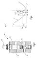
- the conditions are illustrated in Figure 4. It is assumed that a press with a high stroke rate.
- a first curve I illustrates the path X of the plunger 9 over the rotation angle ⁇ of the eccentric shaft. It is assumed that there is an approximate sinusoidal relationship.
- the sheet holder plate 17 is set on the workpiece.
- the curve II illustrates the mass flow of the displaced from the hydraulic cylinders 19, 20 hydraulic fluid.
- a press angle ⁇ 1 which certainly after the Placing the blank holder plate 17 on the workpiece 16 and certainly before the breakthrough of the stamps 13, 14, 15 through the workpiece 16, locks the controller 53 now the bypass valve 52, whereby the sensor device 50th is activated.
- the crank or press angle ⁇ 1 can as a criterion for releasing the sensor device 50 and the valve device 48 are also used that the Tappet 9 passes through the point x1.
- the monitoring is the press angle preferred because of this better Resolution offers.
- the threshold m ⁇ th for the valve device 48 can be set very low, so that the otherwise observed punching stroke on a almost no more perceptible minimum.
- the fluid flow monitored from the hydraulic cylinders 19, 20, can also find other sensor devices application.
- this Press angle ⁇ 1, ⁇ 2 dynamically adapt. This can be, for example done by placing ⁇ 1 in a given or insertable angular distance before punching breakthrough and ⁇ 2 in a fixed or adjustable angular distance after the Punch breakthrough is set. As press angle of the Punch breakthrough is then the press angle from the previous punch stroke or an average value from previous Used punching strokes.
- the press frame, the press table or other parts of the press Force sensors to accommodate a deformation of the concerned press element or directly on in the Press acting force.
- Such can be, for example Be force sensors in the tool 10.
- the ones of these Sensors emitted signals can be sent to the control device 53 are guided and serve the press angle ⁇ 1, ⁇ 2 set.
- the sensor device 50 can a time, i. then be released when to the Stamping 13, 14, 15 recorded a significant increase in strength is. There is no false trip at this time the valve device 48 to fear more, because the relative movement between the blank holder plate 17 and the punches 13, 14, 15 is almost zero.
- the system according to the invention allows a substantial Increase the holding force, especially during the Performing the punching operation, i. while the stamps 13, 14, 15 penetrate through the material of the workpiece.
- the real one Cutting force can thereby up to a sixth of the theoretical thrust can be lowered.
- the sheet holding device 21 causes a particularly firm clamping of Workpiece 16 and thus causes an improvement of Cut as well as a cutting shock absorption.
- the press 1 is so biased that compensates or compensates for games become. This leads compared to classical cutting impact damping systems for reducing the total pressing force of the system. This also means that older Presses continue even for difficult separation operations can be used.
- the force exerted on the sheet holder plate Force is preferably about 40% of the pressing force designed.
- the separation process can be achieved by using a fast evaluation and control device, such as the Control device 53, monitored, evaluated and controlled become.
- the system can be largely self-sufficient, i. of the Press 1 independently trained and used. For example It can be part of the tool, and thus in principle be used in different presses.
- At Change of press data can be press-specific parameters changed via program or system-specific flashcards become.
- the pressures in the hydraulic cylinders 19, 20 can encoder- or path-dependent permanently monitored.
- the resulting envelopes allow for permanent process monitoring.
- the control of the bypass valve 52 takes place crank angle or path dependent on the same system.
- the process data and faults can be accessed via data storage systems stored and tracked in case of damage. In addition, systems for detecting overload cases be provided.
- a sheet holder 21st provided that the relevant workpiece 16 during the Clamping firmly clamped.
- the clamping force will increase up to 40% or more percent of the ram force increased.
- the force exerted by the sheet holding device during the workpiece breakthrough be increased again.
- an efficient cutting impact reduction or prevention at the press results.
- a cutting blow is significantly weakened or does not occur.
Landscapes
- Engineering & Computer Science (AREA)
- Mechanical Engineering (AREA)
- Shaping Metal By Deep-Drawing, Or The Like (AREA)
- Punching Or Piercing (AREA)
- Control Of Presses (AREA)
- Press Drives And Press Lines (AREA)
- Shearing Machines (AREA)
Abstract
Description
- Figur 1
- die erfindungsgemäße Presse in schematisierter Übersichtsdarstellung,
- Figur 2
- das Werkzeug der Presse nach Figur 1 in einer schematisierten Vertikalschnittdarstellung,
- Figur 3
- ein Ventil zur Überwachung eines von dem Werkzeug nach Figur 2 erzeugten Hydraulikfluidflusses und
- Figur 4
- Diagramme zur Veranschaulichung der Abhängigkeit des Stößelhubs vom Pressenwinkel sowie des Massenstroms des aus der Blechhalteeinrichtung verdrängten Fluidflusses vom Stößelhub.
Claims (23)
- Presse (1), insbesondere zum Stanzen von Blechen,
mit einem Pressengestell, zu dem ein Pressentisch (4) zur Aufnahme eines Unterwerkzeuges (12) gehört und in dem ein Stößel (9) beweglich gelagert ist, der mit einer Antriebseinrichtung (6) in Verbindung steht und ein Oberwerkzeug (11) trägt,
mit einer steuerbaren Blechhalteeinrichtung (21), die zu dem Werkzeug (10) gehört und die das Werkstück (16) während des Umformvorganges gegen das Unterwerkzeug (12) presst und sich dazu mit einem Ende an dem Stößel (9) und mit ihrem anderen Ende auf dem Werkstück (16) abstützt,
mit einer Steuereinrichtung (51, 53), die der Blechhalteeinrichtung (21) zugeordnet ist und die die von der Blechhalteeinrichtung (21) ausgeübte, zwischen dem Stößel (9) und dem Werkstück (16) wirkende Kraft beeinflusst. - Presse nach Anspruch 1, dadurch gekennzeichnet, dass die Blechhalteeinrichtung (21) wenigstens einen Hydraulikzylinder (19) aufweist, der an ein Hydrauliksystem (37) angeschlossen ist, das den Hydraulikzylinder (19) mit einem unter Druck stehenden Hydraulikfluid beaufschlagt.
- Presse nach Anspruch 1, dadurch gekennzeichnet, dass das Hydrauliksystem (37) wenigstens einen ersten hydraulischen Druckspeicher (38) aufweist.
- Presse nach Anspruch 1, dadurch gekennzeichnet, dass das Hydrauliksystem (37) wenigstens einen zweiten hydraulischen Druckspeicher (39) aufweist.
- Presse nach Anspruch 2, dadurch gekennzeichnet, dass die Steuereinrichtung (51) eine Ventileinrichtung (48) zur Steuerung des Hydraulikflusses aus dem Hydraulikzylinder (19, 20) sowie eine Sensoreinrichtung (50) umfasst, die die Ventileinrichtung (48) steuert.
- Presse nach Anspruch 5, dadurch gekennzeichnet, dass die Sensoreinrichtung (50) dazu eingerichtet ist, das Überschreiten eines Geschwindigkeitsschwellwertes der Relativbewegung zwischen dem Oberwerkzeug (11) und dem Werkstück (16) zu erfassen.
- Presse nach Anspruch 6, dadurch gekennzeichnet, dass die Ventileinrichtung (48) und die Sensoreinrichtung (50) durch ein durchflussempfindliches Ventil gebildet sind.
- Presse nach Anspruch 1, dadurch gekennzeichnet, dass die Steuereinrichtung (51) dazu eingerichtet ist, die von der Blechhalteeinrichtung (21) ausgeübte Kraft sprunghaft zu erhöhen, wenn das Überschreiten eines Geschwindigkeitsschwellwertes der Relativbewegung zwischen dem Oberwerkzeug (11) und dem Werkstück (16) festgestellt wird.
- Presse nach Anspruch 5, dadurch gekennzeichnet, dass die Steuereinrichtung (51, 53) mit einer Gebereinrichtung (54, 55) zur Erfassung der aktuellen Stößelposition oder einer anderen Größe verbunden ist, die mit der Stößelposition in einem eindeutigen Zusammenhang steht.
- Presse nach Anspruch 1, dadurch gekennzeichnet, dass die Steuereinrichtung (51, 53) eine sprungartige Änderung der von der Blechhalteeinrichtung () aufgebrachten Kraft nur für einen abgegrenzten Abschnitt des Stößelweges freigibt.
- Presse (1), insbesondere zum Stanzen von Blechen,
mit einem Pressengestell, zu dem ein Pressentisch (4) zur Aufnahme eines Unterwerkzeuges (12) gehört und in dem ein Stößel (9) in Stößelbewegungsrichtung beweglich gelagert ist, der mit einer Antriebseinrichtung (6) in Verbindung steht und ein Oberwerkzeug (11) trägt,
mit einer steuerbaren Abstützeinrichtung (21), die wenigstens zeitweilig gegen die Stößelarbeitsrichtung gegen den Stößel (9) drückt,
mit einer Steuereinrichtung (51, 53), die der Abstützeinrichtung (21) zugeordnet ist und die das Überschreiten eines Geschwindigkeitsschwellwertes der Relativbewegung zwischen dem Oberwerkzeug (11) und dem Werkstück (16) erfasst und anhand dessen die von der Abstützeinrichtung (21) ausgeübte, zwischen dem Stößel (9) und dem Werkstück (16) wirkende Kraft beeinflusst,
wobei die Steuereinrichtung (51, 53) die Beeinflussung der von der Abstützeinrichtung (21) aufgebrachten Kraft nur innerhalb eines Freigabe-Wegabschnitts der Stößelbewegung freigibt. - Presse nach Anspruch 11, dadurch gekennzeichnet, dass die Abstützeinrichtung (21) eine Blechhalteeinrichtung (21) ist.
- Presse nach Anspruch 11, dadurch gekennzeichnet, dass die Abstützeinrichtung (21) wenigstens einen Hydraulikzylinder (19, 20) aufweist, der an ein Hydrauliksystem (37) angeschlossen ist, das den Hydraulikzylinder (19, 20) mit einem unter Druck stehenden Hydraulikfluid beaufschlagt.
- Presse nach Anspruch 13, dadurch gekennzeichnet, dass das Hydrauliksystem (37) wenigstens einen ersten hydraulischen Druckspeicher (38) aufweist.
- Presse nach Anspruch 13, dadurch gekennzeichnet, dass das Hydrauliksystem (37) wenigstens einen zweiten hydraulischen Druckspeicher (39) aufweist.
- Presse nach Anspruch 13, dadurch gekennzeichnet, dass die Steuereinrichtung (51, 53) eine Ventileinrichtung (48) zur Steuerung des Hydraulikflusses aus dem Hydraulikzylinder (19, 20) sowie eine Sensoreinrichtung (50) umfasst, die die Ventileinrichtung (48) steuert.
- Presse nach Anspruch 16, dadurch gekennzeichnet, dass die Sensoreinrichtung (50) dazu eingerichtet ist, das Überschreiten eines Geschwindigkeitsschwellwertes der Relativbewegung zwischen dem Oberwerkzeug (11) und dem Werkstück (16) zu erfassen.
- Presse nach Anspruch 17, dadurch gekennzeichnet, dass die Ventileinrichtung (48) und die Sensoreinrichtung (50) durch ein durchflussempfindliches Ventil gebildet sind.
- Presse nach Anspruch 11, dadurch gekennzeichnet, dass die Steuereinrichtung (51, 53) dazu eingerichtet ist, die von der Abstützeinrichtung (21) ausgeübte Kraft sprunghaft zu erhöhen, wenn das Überschreiten eines Geschwindigkeitsschwellwertes der Relativbewegung zwischen dem Oberwerkzeug (11) und dem Werkstück (16) festgestellt wird.
- Presse nach Anspruch 11, dadurch gekennzeichnet, dass die Steuereinrichtung (51, 53) mit einer Gebereinrichtung (54, 55) zur Erfassung der aktuellen Stößelposition oder einer anderen Größe verbunden ist, die mit der Stößelposition in einem eindeutigen Zusammenhang steht.
- Presse nach Anspruch 11, dadurch gekennzeichnet, dass der festgelegte Wegabschnitt einen einstellbaren Anfang ϕ1, x1 aufweist.
- Presse nach Anspruch 11, dadurch gekennzeichnet, dass der festgelegte Wegabschnitt ein einstellbaren Anfang ϕ2, x2 aufweist.
- Presse nach Anspruch 11, dadurch gekennzeichnet, dass der Freigabe-Wegabschnitt während des Betriebs der Presse (1) von einem ausgewählten Parameter abhängig eingestellt wird.
Priority Applications (1)
| Application Number | Priority Date | Filing Date | Title |
|---|---|---|---|
| EP08160025A EP1985389B1 (de) | 2004-06-02 | 2005-05-18 | Presse zum Schneiden von hochfesten Blechen |
Applications Claiming Priority (4)
| Application Number | Priority Date | Filing Date | Title |
|---|---|---|---|
| DE102004027017 | 2004-06-02 | ||
| DE102004027017 | 2004-06-02 | ||
| DE102005021028 | 2005-05-06 | ||
| DE102005021028A DE102005021028B4 (de) | 2004-06-02 | 2005-05-06 | Presse zum Schneiden von hochfesten Blechen |
Related Child Applications (2)
| Application Number | Title | Priority Date | Filing Date |
|---|---|---|---|
| EP08160025A Division EP1985389B1 (de) | 2004-06-02 | 2005-05-18 | Presse zum Schneiden von hochfesten Blechen |
| EP08160025.6 Division-Into | 2008-07-09 |
Publications (2)
| Publication Number | Publication Date |
|---|---|
| EP1602419A1 true EP1602419A1 (de) | 2005-12-07 |
| EP1602419B1 EP1602419B1 (de) | 2010-06-23 |
Family
ID=34936621
Family Applications (2)
| Application Number | Title | Priority Date | Filing Date |
|---|---|---|---|
| EP20050010716 Expired - Lifetime EP1602419B1 (de) | 2004-06-02 | 2005-05-18 | Presse zum Schneiden von hochfesten Blechen |
| EP08160025A Expired - Lifetime EP1985389B1 (de) | 2004-06-02 | 2005-05-18 | Presse zum Schneiden von hochfesten Blechen |
Family Applications After (1)
| Application Number | Title | Priority Date | Filing Date |
|---|---|---|---|
| EP08160025A Expired - Lifetime EP1985389B1 (de) | 2004-06-02 | 2005-05-18 | Presse zum Schneiden von hochfesten Blechen |
Country Status (3)
| Country | Link |
|---|---|
| EP (2) | EP1602419B1 (de) |
| DE (2) | DE102005021028B4 (de) |
| ES (2) | ES2381607T3 (de) |
Cited By (5)
| Publication number | Priority date | Publication date | Assignee | Title |
|---|---|---|---|---|
| EP1782897A2 (de) | 2005-11-07 | 2007-05-09 | Schuler Pressen GmbH & Co. KG | Presse mit Schnittschlagdämpfung |
| DE102006039463A1 (de) * | 2006-08-23 | 2008-02-28 | Müller Weingarten AG | Verfahren und Vorrichtung zur Schnittschlagdämpfung |
| WO2011038947A1 (de) * | 2009-09-29 | 2011-04-07 | Voith Patent Gmbh | Vorrichtung und verfahren zur schnittschlagdämpfung für arbeitsmaschinen |
| DE102014111241A1 (de) | 2014-08-07 | 2016-02-11 | Schuler Pressen Gmbh | Blech- oder Sinterteil für einen Stator oder einen Läufer einer elektrischen Maschine sowie Verfahren zu dessen Herstellung |
| CN113415779A (zh) * | 2021-07-03 | 2021-09-21 | 江西乔扬数控设备有限公司 | 一种闭式压力机自动注油装置 |
Families Citing this family (2)
| Publication number | Priority date | Publication date | Assignee | Title |
|---|---|---|---|---|
| CN104384291B (zh) * | 2014-10-08 | 2016-08-24 | 四川百世昌重型机械有限公司 | 液压机缓冲调节与机械定程复合装置 |
| DE102015106859B4 (de) | 2015-05-04 | 2018-06-14 | Fraunhofer-Gesellschaft zur Förderung der angewandten Forschung e.V. | Verfahren zum Scherschneiden hochfester Werkstoffe und Schneidwerkzeuganordnung |
Citations (5)
| Publication number | Priority date | Publication date | Assignee | Title |
|---|---|---|---|---|
| US2290743A (en) * | 1939-12-11 | 1942-07-21 | Hydraulic Dev Corp Inc | Blank-holder press |
| DE2808091A1 (de) * | 1978-02-24 | 1979-08-30 | Moog Gmbh | Einrichtung zum daempfen des schnittschlags bei hydraulischen pressen |
| DE2928777A1 (de) * | 1979-07-17 | 1981-02-05 | Profil Verbindungstechnik Gmbh | Schlagdaempfer zur laermreduzierung bei maschinen mit hin- und hergehenden maschinenteilen |
| EP0475923A1 (de) * | 1990-08-30 | 1992-03-18 | Recherche et Développement GROUPE COCKERILL SAMBRE | Vorrichtung zur Kraftregulierung der Niederhalter einer Presse |
| DE10252625A1 (de) * | 2001-11-14 | 2003-05-28 | Schuler Pressen Gmbh & Co | Presse mit Schnittschlagreduzierung |
Family Cites Families (2)
| Publication number | Priority date | Publication date | Assignee | Title |
|---|---|---|---|---|
| JP3319786B2 (ja) * | 1992-09-02 | 2002-09-03 | 株式会社小松製作所 | プレスのブレークスルー緩衝装置およびその制御方法 |
| BE1010313A3 (fr) * | 1996-05-30 | 1998-06-02 | S C Rech Et Dev Groupe Cockeri | Amelioration au systeme de regulation de la force de serre-flan dans une presse. |
-
2005
- 2005-05-06 DE DE102005021028A patent/DE102005021028B4/de not_active Expired - Fee Related
- 2005-05-18 ES ES08160025T patent/ES2381607T3/es not_active Expired - Lifetime
- 2005-05-18 ES ES05010716T patent/ES2346980T3/es not_active Expired - Lifetime
- 2005-05-18 EP EP20050010716 patent/EP1602419B1/de not_active Expired - Lifetime
- 2005-05-18 DE DE200550009780 patent/DE502005009780D1/de not_active Expired - Lifetime
- 2005-05-18 EP EP08160025A patent/EP1985389B1/de not_active Expired - Lifetime
Patent Citations (5)
| Publication number | Priority date | Publication date | Assignee | Title |
|---|---|---|---|---|
| US2290743A (en) * | 1939-12-11 | 1942-07-21 | Hydraulic Dev Corp Inc | Blank-holder press |
| DE2808091A1 (de) * | 1978-02-24 | 1979-08-30 | Moog Gmbh | Einrichtung zum daempfen des schnittschlags bei hydraulischen pressen |
| DE2928777A1 (de) * | 1979-07-17 | 1981-02-05 | Profil Verbindungstechnik Gmbh | Schlagdaempfer zur laermreduzierung bei maschinen mit hin- und hergehenden maschinenteilen |
| EP0475923A1 (de) * | 1990-08-30 | 1992-03-18 | Recherche et Développement GROUPE COCKERILL SAMBRE | Vorrichtung zur Kraftregulierung der Niederhalter einer Presse |
| DE10252625A1 (de) * | 2001-11-14 | 2003-05-28 | Schuler Pressen Gmbh & Co | Presse mit Schnittschlagreduzierung |
Cited By (11)
| Publication number | Priority date | Publication date | Assignee | Title |
|---|---|---|---|---|
| EP1782897A2 (de) | 2005-11-07 | 2007-05-09 | Schuler Pressen GmbH & Co. KG | Presse mit Schnittschlagdämpfung |
| EP1782897A3 (de) * | 2005-11-07 | 2008-05-21 | Schuler Pressen GmbH & Co. KG | Presse mit Schnittschlagdämpfung |
| US8302517B2 (en) | 2005-11-07 | 2012-11-06 | Schuler Pressen Gmbh & Co. Kg | Press with cutting shock dampening |
| DE102006039463A1 (de) * | 2006-08-23 | 2008-02-28 | Müller Weingarten AG | Verfahren und Vorrichtung zur Schnittschlagdämpfung |
| WO2008022607A1 (de) * | 2006-08-23 | 2008-02-28 | Müller Weingarten AG | Verfahren und vorrichtung zur schnittschlagdämpfung |
| WO2011038947A1 (de) * | 2009-09-29 | 2011-04-07 | Voith Patent Gmbh | Vorrichtung und verfahren zur schnittschlagdämpfung für arbeitsmaschinen |
| CN102612415A (zh) * | 2009-09-29 | 2012-07-25 | 沃依特专利有限责任公司 | 用于做功机器的切割冲击衰减的装置和方法 |
| CN102612415B (zh) * | 2009-09-29 | 2015-03-18 | 沃依特专利有限责任公司 | 用于做功机器的切割冲击衰减的装置和方法 |
| US9050644B2 (en) | 2009-09-29 | 2015-06-09 | Voith Patent Gmbh | Device and method for the cutting shock damping of work machines |
| DE102014111241A1 (de) | 2014-08-07 | 2016-02-11 | Schuler Pressen Gmbh | Blech- oder Sinterteil für einen Stator oder einen Läufer einer elektrischen Maschine sowie Verfahren zu dessen Herstellung |
| CN113415779A (zh) * | 2021-07-03 | 2021-09-21 | 江西乔扬数控设备有限公司 | 一种闭式压力机自动注油装置 |
Also Published As
| Publication number | Publication date |
|---|---|
| DE102005021028A1 (de) | 2005-12-29 |
| ES2346980T3 (es) | 2010-10-22 |
| EP1602419B1 (de) | 2010-06-23 |
| EP1985389A3 (de) | 2008-11-05 |
| EP1985389B1 (de) | 2012-02-01 |
| EP1985389A2 (de) | 2008-10-29 |
| DE102005021028B4 (de) | 2009-06-25 |
| ES2381607T3 (es) | 2012-05-29 |
| DE502005009780D1 (de) | 2010-08-05 |
Similar Documents
| Publication | Publication Date | Title |
|---|---|---|
| EP1758697B1 (de) | Verfahren und presse zum schneiden von hochfestem blech | |
| EP2848329B1 (de) | Verfahren und Vorrichtung zum Präzisionsschneiden von Werkstücken in einer Presse | |
| DE19521050C2 (de) | Kniehebel-Antriebsvorrichtung | |
| WO2009115444A1 (de) | Pulverpresse zur herstellung eines presslings aus metallpulver | |
| EP1782897B1 (de) | Presse mit Schnittschlagdämpfung | |
| DE2824176C2 (de) | ||
| DE102009048483B4 (de) | Schnittschlagdämpfung | |
| EP1602419B1 (de) | Presse zum Schneiden von hochfesten Blechen | |
| EP0335939B1 (de) | Hydraulische antriebsvorrichtung | |
| DE10252625B4 (de) | Presse mit Schnittschlagreduzierung | |
| DE10005023A1 (de) | Presse | |
| CH700864A2 (de) | Feinschneidpresse. | |
| EP0605698B1 (de) | Gelenkhebelpresse | |
| DE2432774B2 (de) | Presse, insbesondere Feinschneidpresse | |
| EP0417753B1 (de) | Mechanische oder hydraulische Presse mit Zieheinrichtung oder Ziehstufe einer Stufenpresse | |
| EP2054177B1 (de) | Verfahren und vorrichtung zur schnittschlagdämpfung | |
| DE2804185A1 (de) | Stossdaempfvorrichtung | |
| DE1957401A1 (de) | Vorrichtung zum Vermindern der Druckschwankungen des Blechhalters von Ziehpressen | |
| DE2812973C2 (de) | Einrichtung zur Dämpfung des Schnittschlages an einer hydraulischen Presse | |
| EP1783576A2 (de) | Hydraulischer Antrieb | |
| DE4006101A1 (de) | Vorrichtung zur erhoehung der leistungsfaehigkeit bei der steuerung bzw. regelung der jedem druckpunkt des blechhalters doppeltwirkender pressen zugeordneten kolben-zylinder-einheit | |
| DE3915263C2 (de) | Spindelpresse | |
| DE102012207429B4 (de) | Blechbearbeitungswerkzeug mit einem am Werkzeugoberteil gehaltenen relativbeweglichen Niederhalter und mit einer Mitnehmereinrichtung sowie einer Entlastungseinrichtung für diesen Niederhalter | |
| DE2746170A1 (de) | Schnittschlagdaempfvorrichtung fuer pressen | |
| DE102023002604A1 (de) | Presse für Hochgeschwindigkeitsschneidfunktion, immanenter Schnittschlagminimation, sowie kostengünstiger Presskraft-Erweiterung mittels eines direkt auf den Pressenstößel wirkenden und an den Umformvorgang optimal angepassten Impulsionsantriebs |
Legal Events
| Date | Code | Title | Description |
|---|---|---|---|
| PUAI | Public reference made under article 153(3) epc to a published international application that has entered the european phase |
Free format text: ORIGINAL CODE: 0009012 |
|
| AK | Designated contracting states |
Kind code of ref document: A1 Designated state(s): AT BE BG CH CY CZ DE DK EE ES FI FR GB GR HU IE IS IT LI LT LU MC NL PL PT RO SE SI SK TR |
|
| AX | Request for extension of the european patent |
Extension state: AL BA HR LV MK YU |
|
| 17P | Request for examination filed |
Effective date: 20060221 |
|
| AKX | Designation fees paid |
Designated state(s): DE ES IT |
|
| RBV | Designated contracting states (corrected) |
Designated state(s): DE ES FR IT |
|
| 17Q | First examination report despatched |
Effective date: 20061109 |
|
| GRAP | Despatch of communication of intention to grant a patent |
Free format text: ORIGINAL CODE: EPIDOSNIGR1 |
|
| GRAS | Grant fee paid |
Free format text: ORIGINAL CODE: EPIDOSNIGR3 |
|
| GRAA | (expected) grant |
Free format text: ORIGINAL CODE: 0009210 |
|
| AK | Designated contracting states |
Kind code of ref document: B1 Designated state(s): DE ES FR IT |
|
| REF | Corresponds to: |
Ref document number: 502005009780 Country of ref document: DE Date of ref document: 20100805 Kind code of ref document: P |
|
| REG | Reference to a national code |
Ref country code: ES Ref legal event code: FG2A Ref document number: 2346980 Country of ref document: ES Kind code of ref document: T3 |
|
| PLBE | No opposition filed within time limit |
Free format text: ORIGINAL CODE: 0009261 |
|
| STAA | Information on the status of an ep patent application or granted ep patent |
Free format text: STATUS: NO OPPOSITION FILED WITHIN TIME LIMIT |
|
| 26N | No opposition filed |
Effective date: 20110324 |
|
| REG | Reference to a national code |
Ref country code: DE Ref legal event code: R097 Ref document number: 502005009780 Country of ref document: DE Effective date: 20110323 |
|
| REG | Reference to a national code |
Ref country code: FR Ref legal event code: PLFP Year of fee payment: 12 |
|
| REG | Reference to a national code |
Ref country code: FR Ref legal event code: PLFP Year of fee payment: 13 |
|
| REG | Reference to a national code |
Ref country code: FR Ref legal event code: PLFP Year of fee payment: 14 |
|
| PGFP | Annual fee paid to national office [announced via postgrant information from national office to epo] |
Ref country code: DE Payment date: 20180424 Year of fee payment: 14 Ref country code: ES Payment date: 20180626 Year of fee payment: 14 |
|
| PGFP | Annual fee paid to national office [announced via postgrant information from national office to epo] |
Ref country code: FR Payment date: 20180523 Year of fee payment: 14 Ref country code: IT Payment date: 20180518 Year of fee payment: 14 |
|
| REG | Reference to a national code |
Ref country code: DE Ref legal event code: R119 Ref document number: 502005009780 Country of ref document: DE |
|
| PG25 | Lapsed in a contracting state [announced via postgrant information from national office to epo] |
Ref country code: DE Free format text: LAPSE BECAUSE OF NON-PAYMENT OF DUE FEES Effective date: 20191203 Ref country code: IT Free format text: LAPSE BECAUSE OF NON-PAYMENT OF DUE FEES Effective date: 20190518 |
|
| PG25 | Lapsed in a contracting state [announced via postgrant information from national office to epo] |
Ref country code: FR Free format text: LAPSE BECAUSE OF NON-PAYMENT OF DUE FEES Effective date: 20190531 |
|
| REG | Reference to a national code |
Ref country code: ES Ref legal event code: FD2A Effective date: 20200928 |
|
| PG25 | Lapsed in a contracting state [announced via postgrant information from national office to epo] |
Ref country code: ES Free format text: LAPSE BECAUSE OF NON-PAYMENT OF DUE FEES Effective date: 20190519 |