EP1602438A2 - Tool change magazine for laser beam machine - Google Patents
Tool change magazine for laser beam machine Download PDFInfo
- Publication number
- EP1602438A2 EP1602438A2 EP05009902A EP05009902A EP1602438A2 EP 1602438 A2 EP1602438 A2 EP 1602438A2 EP 05009902 A EP05009902 A EP 05009902A EP 05009902 A EP05009902 A EP 05009902A EP 1602438 A2 EP1602438 A2 EP 1602438A2
- Authority
- EP
- European Patent Office
- Prior art keywords
- axis
- tool
- tool change
- laser beam
- machining
- Prior art date
- Legal status (The legal status is an assumption and is not a legal conclusion. Google has not performed a legal analysis and makes no representation as to the accuracy of the status listed.)
- Granted
Links
- 238000003754 machining Methods 0.000 claims abstract description 103
- 230000003287 optical effect Effects 0.000 claims description 7
- 239000000428 dust Substances 0.000 claims description 3
- 239000011159 matrix material Substances 0.000 claims description 3
- 238000010586 diagram Methods 0.000 description 10
- 238000007796 conventional method Methods 0.000 description 2
- 238000011109 contamination Methods 0.000 description 1
- 238000009434 installation Methods 0.000 description 1
- 238000012423 maintenance Methods 0.000 description 1
- 239000000463 material Substances 0.000 description 1
- 239000007921 spray Substances 0.000 description 1
Images


Classifications
-
- B—PERFORMING OPERATIONS; TRANSPORTING
- B23—MACHINE TOOLS; METAL-WORKING NOT OTHERWISE PROVIDED FOR
- B23K—SOLDERING OR UNSOLDERING; WELDING; CLADDING OR PLATING BY SOLDERING OR WELDING; CUTTING BY APPLYING HEAT LOCALLY, e.g. FLAME CUTTING; WORKING BY LASER BEAM
- B23K26/00—Working by laser beam, e.g. welding, cutting or boring
- B23K26/14—Working by laser beam, e.g. welding, cutting or boring using a fluid stream, e.g. a jet of gas, in conjunction with the laser beam; Nozzles therefor
- B23K26/1462—Nozzles; Features related to nozzles
- B23K26/1482—Detachable nozzles, e.g. exchangeable or provided with breakaway lines
-
- Y—GENERAL TAGGING OF NEW TECHNOLOGICAL DEVELOPMENTS; GENERAL TAGGING OF CROSS-SECTIONAL TECHNOLOGIES SPANNING OVER SEVERAL SECTIONS OF THE IPC; TECHNICAL SUBJECTS COVERED BY FORMER USPC CROSS-REFERENCE ART COLLECTIONS [XRACs] AND DIGESTS
- Y10—TECHNICAL SUBJECTS COVERED BY FORMER USPC
- Y10T—TECHNICAL SUBJECTS COVERED BY FORMER US CLASSIFICATION
- Y10T29/00—Metal working
- Y10T29/49—Method of mechanical manufacture
- Y10T29/49995—Shaping one-piece blank by removing material
-
- Y—GENERAL TAGGING OF NEW TECHNOLOGICAL DEVELOPMENTS; GENERAL TAGGING OF CROSS-SECTIONAL TECHNOLOGIES SPANNING OVER SEVERAL SECTIONS OF THE IPC; TECHNICAL SUBJECTS COVERED BY FORMER USPC CROSS-REFERENCE ART COLLECTIONS [XRACs] AND DIGESTS
- Y10—TECHNICAL SUBJECTS COVERED BY FORMER USPC
- Y10T—TECHNICAL SUBJECTS COVERED BY FORMER US CLASSIFICATION
- Y10T483/00—Tool changing
- Y10T483/13—Tool changing with control means energized in response to activator stimulated by condition sensor
-
- Y—GENERAL TAGGING OF NEW TECHNOLOGICAL DEVELOPMENTS; GENERAL TAGGING OF CROSS-SECTIONAL TECHNOLOGIES SPANNING OVER SEVERAL SECTIONS OF THE IPC; TECHNICAL SUBJECTS COVERED BY FORMER USPC CROSS-REFERENCE ART COLLECTIONS [XRACs] AND DIGESTS
- Y10—TECHNICAL SUBJECTS COVERED BY FORMER USPC
- Y10T—TECHNICAL SUBJECTS COVERED BY FORMER US CLASSIFICATION
- Y10T483/00—Tool changing
- Y10T483/17—Tool changing including machine tool or component
- Y10T483/1733—Rotary spindle machine tool [e.g., milling machine, boring, machine, grinding machine, etc.]
- Y10T483/1736—Tool having specific mounting or work treating feature
- Y10T483/1738—Tool head
Definitions
- the present invention relates to a tool change magazine (hereinafter also referred to as a "magazine") which makes it possible to use unskilled operators in operating a laser beam machine, maximize machining quality and productivity for each material and workpiece thickness, and accomplish long, unattended operation.
- a tool change magazine hereinafter also referred to as a "magazine”
- Patent Document 1 Japanese Patent Laid-Open Publication No. 6-304755 (Patent Document 1)
- the plasma machine is equipped with a torch change system comprising a stocker (disk) indexable by an NC system.
- the torch change system described above changes tools using an indexing mechanism, and thus requires an extra drive system (rotational axis) other than linear axes. This increases overall machine cost, makes the machine complex, and lowers reliability.
- the stocker is located in a machining area, making it very dangerous to pick up a tool from the stocker manually for a tool change. Thus, when changing a tool, machining must be stopped, reducing productivity greatly.
- the present invention has an object to provide a laser beam machine equipped with magazines for changing laser machining tools automatically and capable of accomplishing long, unattended operation.
- a laser beam machine comprises, as basic means, a bed, a pallet which is disposed on the bed and holds a workpiece, a column which moves along an X axis, that is, a longitudinal axis of the bed, a saddle which is supported by the column and moves along a Y axis orthogonal to the X axis, and a machining head which is supported by the saddle and moves along a Z axis perpendicular to a plane formed by the X axis and Y axis, and a laser machining tool replaceably attached to the machining head. Further, it comprises the tool change magazine for laser machining tools, the tool change magazine being disposed at an automatic tool change position outside a machining area.
- the laser machining tool comprises a torch which has optical means including a condenser lens; and a nozzle which is replaceably attached to the tip of the torch.
- the tool change magazine is placed on the plane formed by the X axis and the Y axis.
- the tool change magazine is placed on a plane orthogonal to the plane formed by the X axis and the Y axis.
- Tool change magazines are placed in a single row, in multiple rows, or in a matrix. Furthermore, the laser beam machine comprises a dust-proof shutter which covers top of the tool change magazine and opens only when the laser machining tool is changed.
- the tool change magazines for laser machining tools are placed outside the machining area, the tools can be placed meticulously along linear axes, and thus a tool storage area (area occupied by tools) can be minimized.
- the tool change magazines may be arranged not only on a single plane.
- tool change magazines are installed outside the machining area, tools can be attached and detached manually even during machining, allowing operators to work safely.
- the present invention makes it possible to put in and take out tools safely at any time as well as to carry out tool maintenance and tool changes, even during machining without opening a safety cover.
- the replacement tool has a dust-proof shutter mechanism installed at an opening for connection with an external optical path system. Clean air is sprayed from inside the external optical path system with the tool brought as close as possible to a mount of the external optical path system, the shutter is opened while preventing intrusion of air from outside, and the tool is attached to the external optical path system instantaneously. This ability to prevent intrusion of dust from outside makes it possible to prevent contamination of machining lens mounted in the tool, extending the life of the machining lens, and thereby maintaining stable, high-quality machining.
- the number and size of tools are less limited than in the case of the conventional disk-shaped stocker.
- FIG. 1 is a perspective view showing an overall configuration of a laser beam machine according to the present invention
- FIG. 2 is a plan view
- FIG. 3 is a front view
- FIG. 4 is a perspective view of the relevant portion
- FIG. 5 is a side view.
- a laser beam machine generally denoted by reference number 1, has a pallet (table) 20 which is disposed on a bed 10 to carry a plate-shaped workpiece W 1 .
- a pallet changer 12 is placed on the longitudinal extension of the bed 10, and a pallet 20a carrying a workpiece W 2 to be machined next is awaiting its turn.
- a pair of guide rails 34 are installed on both sides of the bed 10 along its length and a column 30 is mounted on the guide rails 34 in such a way as to be movable along an X axis.
- Means for driving the column 30 along the X axis is provided by, for example, a linear motor, which is formed by a stator installed on the guide rails 34 and a moving member installed on a linear-motion guide 32.
- a guide rail 44 is installed on the column 30 along a Y axis orthogonal to the X axis and a saddle 40 is mounted in such a way as to be movable along the Y axis.
- the saddle 40 is equipped with a linear-motion guide 42 which is engaged with the guide rail 44.
- a linear motor is formed by the guide rail 44 and linear-motion guide 42.
- the saddle 40 has a guide rail installed along a Z axis perpendicular to the plane formed by the X axis and Y axis and has a machining head 50 mounted in such a way as to be movable along the Z axis.
- the machining head 50 has an optical system which admits a laser beam from a laser oscillator 72.
- the machining head 50 is equipped replaceably with a laser machining tool 60.
- a machining area is fitted with a cover 90 to ensure safety.
- a power panel 70 and the laser oscillator 72 are disposed adjacent to the bed 10.
- a control panel 80 for use by the operator to give various commands is disposed on a longitudinal end of the bed 10.
- a setup station 100 for laser machining tools is installed on that end of the bed 10 which is closer to the control panel 80.
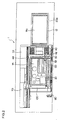
- FIG. 6 is a front view of the setup station 100 for laser machining tools as viewed from the table and
- FIG. 7 is a plan view.
- the setup station 100 for laser machining tools includes a tool station 200 and nozzle station 300, where the tool station 200 is equipped with a tool change magazine for laser machining tools which in turn are equipped with a torch and nozzle while the nozzle station 300 is equipped with a nozzle change magazine for nozzles of laser machining tools.
- FIG. 8(a) is a plan view
- FIG. 8(b) is a front view
- FIG. 8(c) is a side view showing configuration of a tip portion of the machining head 50.
- the machining head 50 contains a laser beam guide tube 51 which is equipped on its outer periphery with a nozzle 52 to spray clean air A 1 .
- the laser machining tool 60 is equipped with a torch 61 and a nozzle 65 which is replaceably attached to a tip portion of the torch 61.
- the laser machining tool 60 removed from the machining head 50 is stored in the magazine 220 in a manner described later and is automatically replaced with a new tool contained in the magazine 220.
- An openable/closable dust-proof shutter 232 is installed above the magazine 220 to protect a condenser lens 611 and the like in a body tube 610 of the torch 61 during tool changes.
- an opening of the torch 61 is covered by the dust-proof shutter 232 and clean air A 1 is sprayed from the nozzle 52 to prevent intrusion of air, dust, dirt, etc. from outside.
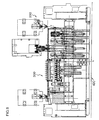
- FIG. 9 is an explanatory diagram illustrating a structure of the tool station 200 of the laser beam machine.
- the tool station 200 of the laser beam machine is located at an end of the bed 10 and has a base 210 which extends along the Y axis.
- a plurality of magazines 220 are arranged along the Y axis on the base 210.
- the laser beam machine is equipped with four magazines 220.
- the number of magazines 220 may be changed as appropriate.
- a magazine cover 222 is installed openably/closably above the magazine 220 and a holder 230 of the laser machining tool 60 is installed in the magazine 220.
- the holder 230 of the laser machining tool 60 is tilted freely by a tilting mechanism 240.
- the holder 230 is raised and lowered freely along the Z axis by a cylinder 250 installed in the magazine 220.
- the holder 230 is equipped with the dust-proof shutter 232 which covers and reveals an upper opening, to protect the top of the stored laser machining tools 60.
- a cover 90 installed around a machining portion of the laser beam machine has an opening 92 which faces the tool station 200.
- An openable/closable hinged door 91 is installed at the opening.
- FIG. 9(c) shows a state in which the holder 230 of the laser machining tool 60 is raised to a tool change position by extending the cylinder 250.
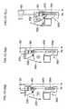
- FIGS. 10-1, 10-2, and 10-3 are explanatory diagrams illustrating operations performed at the tool station 200 of the laser beam machine according to the present invention. They show how a laser machining tool 60 is removed from the machining head 50 and returned to the tool station 200.
- FIG. 10-1(a) shows a state in which laser machining is in progress.
- the holder 230 is stored in the magazine 220, the magazine cover 222 is closed, and the dust-proof shutter 232 is open.
- ATC automatic tool change
- the machining head 50 moves to ATC position X 0 on the X axis.
- the cylinder 250 in the magazine 220 pushes the holder 230 to the position where the latter can receive the laser machining tool 60 from the machining head 50.
- the machining head 50 is lowered and the laser machining tool 60 is clamped in the holder 230.
- the laser machining tool 60 is lowered and the machining head 50 is raised and unclamped.
- the dust-proof shutter 232 of the holder 230 is closed to protect the top of the laser machining tool.
- the machining head 50 is returned to the origin position on the Z axis, the cylinder 250 is compressed to lower the holder 230, and the removal of the laser machining tool 60 is completed.
- FIG. 11 is a flowchart showing the operation of FIG. 10 described above.
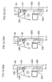
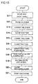
- FIGS. 12-1, 12-2, and 12-3 show how the laser machining tool 60 stored in a magazine 220 at the tool station 200 of the laser beam machine is mounted on the machining head 50.
- FIG. 12-1(a) shows a state in which the machining head 50 with the laser machining tool 60 removed has returned to the ATC origin position X above a specified magazine 220.
- FIG. 12-1(b) shows a state in which the holder 230 containing the laser machining tool 60 has been raised to the ATC position X 0 by extending the cylinder 250.
- FIG. 12-2(e) the machining head 50 is lowered to the ATC position X 0 .
- the laser machining tool 60 is clamped to the machining head 50.
- the machining head 50 is returned to the origin position on the Z axis, and the holder 230 is stored by compressing the cylinder 250.
- the X axis is moved to the ATC origin position X 1 , and the machining head 50 is returned to the Y axis (to waiting position in ATC mode).
- FIG. 13 is a flowchart showing the operations described with reference to FIG. 12.
- the tool change magazines 220 are arranged in a single row on the tool setup station 100 at an end of the bed 10.
- tool change magazines 220 may be arranged in multiple rows or in a matrix.
- the tool change magazines 220 may be placed not only in a plane formed by the X axis and Y axis, but also placed at multiple levels in a plane (e.g., along a Z axis) orthogonal to the plane formed by the X axis and the Y axis.
- linear motor has been cited in the above example as a driving means along the X and Y axes
- present invention can also employ a ball screw.
Landscapes
- Physics & Mathematics (AREA)
- Optics & Photonics (AREA)
- Engineering & Computer Science (AREA)
- Plasma & Fusion (AREA)
- Mechanical Engineering (AREA)
- Laser Beam Processing (AREA)
- Automatic Tool Replacement In Machine Tools (AREA)
Abstract
Description
Claims (8)
- A tool change magazine for a laser beam machine that comprises a bed, a pallet which is disposed on the bed and holds a workpiece, a column which moves along an X axis, that is, a longitudinal axis of the bed, a saddle which is supported by the column and moves along a Y axis orthogonal to the X axis, a machining head which is supported by the saddle and moves along a Z axis perpendicular to a plane formed by the X axis and Y axis, and a laser machining tool replaceably attached to the machining head, characterized in that the laser beam machine comprises the tool change magazine for laser machining tools, the tool change magazine being disposed at an automatic tool change position outside a machining area.
- The tool change magazine for a laser beam machine according to claim 1, characterized in that the laser machining tool comprises a torch which has optical means including a condenser lens; and a nozzle which is replaceably attached to the tip of the torch.
- The tool change magazine for a laser beam machine according to claim 1, characterized in that the tool change magazine is placed on the plane formed by the X axis and the Y axis.
- The tool change magazine for a laser beam machine according to claim 1, characterized in that the tool change magazine is placed on a plane orthogonal to the plane formed by the X axis and the Y axis.
- The tool change magazine for a laser beam machine according to claim 3 or 4, characterized in that tool change magazines are placed in a single row, in multiple rows, or in a matrix.
- A tool change magazine for a laser beam machine that comprises a bed, a pallet which is disposed on the bed and holds a workpiece, a column which moves along an X axis, that is, a longitudinal axis of the bed, a saddle which is supported by the column and moves along a Y axis orthogonal to the X axis, a machining head which is supported by the saddle and moves along a Z axis perpendicular to a plane formed by the X axis and Y axis, and a laser machining tool replaceably attached to the machining head, characterized in that the laser beam machine comprises the tool change magazine for laser machining tools, and a dust-proof shutter which covers top of the tool change magazine and opens only when the laser machining tool is changed.
- The tool change magazine for a laser beam machine according to claim 6, characterized in that the dust-proof shutter can determine difference between internal pressure and external pressure and prevent intrusion of air or dust from outside.
- The tool change magazine for a laser beam machine according to claim 1, characterized in that a control panel for use by an operator to give various operation commands is disposed at a longitudinal end of the bed.
Applications Claiming Priority (2)
| Application Number | Priority Date | Filing Date | Title |
|---|---|---|---|
| JP2004155917A JP2005334920A (en) | 2004-05-26 | 2004-05-26 | Tool-changing magazine in laser beam machine |
| JP2004155917 | 2004-05-26 |
Publications (3)
| Publication Number | Publication Date |
|---|---|
| EP1602438A2 true EP1602438A2 (en) | 2005-12-07 |
| EP1602438A3 EP1602438A3 (en) | 2008-10-01 |
| EP1602438B1 EP1602438B1 (en) | 2012-07-11 |
Family
ID=34936209
Family Applications (1)
| Application Number | Title | Priority Date | Filing Date |
|---|---|---|---|
| EP05009902A Expired - Lifetime EP1602438B1 (en) | 2004-05-26 | 2005-05-06 | Tool change magazine for laser beam machine |
Country Status (4)
| Country | Link |
|---|---|
| US (1) | US7169100B2 (en) |
| EP (1) | EP1602438B1 (en) |
| JP (1) | JP2005334920A (en) |
| CN (1) | CN100404189C (en) |
Cited By (8)
| Publication number | Priority date | Publication date | Assignee | Title |
|---|---|---|---|---|
| EP2078585A1 (en) * | 2008-01-12 | 2009-07-15 | Trumpf Maschinen AG | Mechanical device for assembling and/or disassembling a laser nozzle and laser processing machine with such a device |
| EP2108475A1 (en) | 2008-04-09 | 2009-10-14 | Bystronic Laser AG | Device and method for automatically exchanging cutting nozzles |
| EP1894664A3 (en) * | 2006-08-29 | 2010-04-07 | Yamazaki Mazak Corporation | Automatic tool changer of laser beam machine |
| EP1894665A3 (en) * | 2006-08-29 | 2010-04-07 | Yamazaki Mazak Corporation | Automatic tool changer of laser beam machine |
| US8366593B2 (en) | 2008-01-12 | 2013-02-05 | Trumpf Werkzeugmaschinen Gmbh + Co. Kg | Laser nozzle changing device |
| CN101524806B (en) * | 2008-01-12 | 2013-03-06 | 通快机械股份公司 | Mechanical apparatus assembling and disassembling laser nozzle and laser processing machine using the same |
| US8439811B2 (en) | 2008-01-12 | 2013-05-14 | Trumpf Maschinen Ag | Laser nozzle changing device |
| WO2021058391A1 (en) * | 2019-09-26 | 2021-04-01 | Trumpf Laser- Und Systemtechnik Gmbh | Processing head for a processing machine, processing machine and method for processing a material by means of a processing machine |
Families Citing this family (10)
| Publication number | Priority date | Publication date | Assignee | Title |
|---|---|---|---|---|
| JP2005334921A (en) * | 2004-05-26 | 2005-12-08 | Yamazaki Mazak Corp | Nozzle-changing magazine in laser beam machine |
| DE102007059566B3 (en) * | 2007-12-11 | 2009-07-30 | Leica Biosystems Nussloch Gmbh | Cassette changing device and method for changing cassettes |
| JP6033368B1 (en) * | 2015-06-15 | 2016-11-30 | Dmg森精機株式会社 | Processing machine |
| KR101896320B1 (en) * | 2016-03-04 | 2018-09-07 | 기아자동차 주식회사 | Gdl cutting system of fuel cell |
| DE102016209285B3 (en) * | 2016-05-30 | 2017-08-17 | Trumpf Maschinen Ag | Processing machine with a nozzle changer |
| JP6563622B1 (en) | 2018-09-06 | 2019-08-21 | ヤマザキマザック株式会社 | Tool storage device, machine tool and combined processing machine |
| CN111618431B (en) * | 2020-06-08 | 2022-04-29 | 松山湖材料实验室 | Laser equipment gas nozzle control method and system |
| US20240261866A1 (en) * | 2021-06-04 | 2024-08-08 | Dmg Mori Co., Ltd. | Work Machine |
| CN114226393B (en) * | 2021-12-30 | 2024-12-31 | 岗春激光科技(江苏)有限公司 | A cleaning system for laser equipment |
| JP7757252B2 (en) * | 2022-08-23 | 2025-10-21 | 株式会社神戸製鋼所 | Additive manufacturing system, control method, and program |
Citations (7)
| Publication number | Priority date | Publication date | Assignee | Title |
|---|---|---|---|---|
| JPH0455082A (en) | 1990-06-25 | 1992-02-21 | Amada Co Ltd | Laser beam machine |
| JPH04309487A (en) | 1991-04-09 | 1992-11-02 | Amada Co Ltd | Laser beam machine |
| JPH06304755A (en) | 1993-02-23 | 1994-11-01 | Amada Co Ltd | Torch exchanging system |
| JPH07185865A (en) | 1993-12-27 | 1995-07-25 | Amada Co Ltd | Nozzle exchanging device for laser beam machine |
| US5854460A (en) | 1996-05-07 | 1998-12-29 | Cincinnati Incorporated | Linear motor driven laser cutting machine |
| EP1250975A2 (en) | 2001-04-20 | 2002-10-23 | Yamazaki Mazak Kabushiki Kaisha | Laser beam hardening device |
| JP2004155917A (en) | 2002-11-07 | 2004-06-03 | Kohjin Co Ltd | Antibacterial polyamide film |
Family Cites Families (15)
| Publication number | Priority date | Publication date | Assignee | Title |
|---|---|---|---|---|
| US3650178A (en) * | 1970-01-08 | 1972-03-21 | Joe S Appleton | Multi-purpose multi-motion machine tool |
| US4559684A (en) * | 1981-02-27 | 1985-12-24 | Pryor Timothy R | Controlled machining of combustion chambers, gears and other surfaces |
| JPS58149101A (en) * | 1982-02-26 | 1983-09-05 | Om Seisakusho:Kk | Combined machine tool |
| GB2129349B (en) * | 1982-09-23 | 1986-01-02 | Beaver Machine Tool Sales Limi | Plano-milling machine |
| CN1004996B (en) * | 1985-07-31 | 1989-08-16 | 东芝机械株式会社 | Tool automatic changing device |
| DE3636498A1 (en) * | 1986-10-27 | 1988-05-05 | Maho Werkzeugmaschbau Babel | TOOL CHANGER FOR PROGRAM-CONTROLLED UNIVERSAL MILLING AND DRILLING MACHINES |
| CN1161267A (en) * | 1995-09-14 | 1997-10-08 | 邵文远 | Compositions of metal-working machines |
| JPH1043879A (en) * | 1996-08-05 | 1998-02-17 | Amada Co Ltd | Laser beam machine and method of automatically exchanging nozzle tip using same machine |
| JP2788231B2 (en) * | 1996-09-04 | 1998-08-20 | 川崎重工業株式会社 | Long bar material processing apparatus and processing method |
| JPH1085967A (en) * | 1996-09-20 | 1998-04-07 | Matsushita Electric Ind Co Ltd | Laser-induced plasma detection method, laser control method and laser processing machine using the same |
| JP2000126888A (en) * | 1998-10-21 | 2000-05-09 | Nippei Toyama Corp | Laser processing equipment |
| EP1114694B1 (en) * | 1999-02-26 | 2004-04-28 | Mori Seiki Co., Ltd. | Machine tool |
| US6347259B1 (en) * | 1999-04-01 | 2002-02-12 | Virtek Vision International Inc. | High precision positioning device and method of operating same |
| ES2294062T3 (en) * | 2001-05-17 | 2008-04-01 | CHIRON-WERKE GMBH & CO. KG | MACHINE TOOL AND PROCEDURE FOR MECHANIZATION OF A PART TO BE PREPARED IN THE FORM OF A BAR. |
| JP4111309B2 (en) | 2001-12-17 | 2008-07-02 | 株式会社アマダ | Automatic lens changer for laser processing machines |
-
2004
- 2004-05-26 JP JP2004155917A patent/JP2005334920A/en active Pending
-
2005
- 2005-05-04 US US11/121,428 patent/US7169100B2/en not_active Expired - Lifetime
- 2005-05-06 EP EP05009902A patent/EP1602438B1/en not_active Expired - Lifetime
- 2005-05-24 CN CNB2005100737875A patent/CN100404189C/en not_active Expired - Fee Related
Patent Citations (7)
| Publication number | Priority date | Publication date | Assignee | Title |
|---|---|---|---|---|
| JPH0455082A (en) | 1990-06-25 | 1992-02-21 | Amada Co Ltd | Laser beam machine |
| JPH04309487A (en) | 1991-04-09 | 1992-11-02 | Amada Co Ltd | Laser beam machine |
| JPH06304755A (en) | 1993-02-23 | 1994-11-01 | Amada Co Ltd | Torch exchanging system |
| JPH07185865A (en) | 1993-12-27 | 1995-07-25 | Amada Co Ltd | Nozzle exchanging device for laser beam machine |
| US5854460A (en) | 1996-05-07 | 1998-12-29 | Cincinnati Incorporated | Linear motor driven laser cutting machine |
| EP1250975A2 (en) | 2001-04-20 | 2002-10-23 | Yamazaki Mazak Kabushiki Kaisha | Laser beam hardening device |
| JP2004155917A (en) | 2002-11-07 | 2004-06-03 | Kohjin Co Ltd | Antibacterial polyamide film |
Cited By (11)
| Publication number | Priority date | Publication date | Assignee | Title |
|---|---|---|---|---|
| EP1894664A3 (en) * | 2006-08-29 | 2010-04-07 | Yamazaki Mazak Corporation | Automatic tool changer of laser beam machine |
| EP1894665A3 (en) * | 2006-08-29 | 2010-04-07 | Yamazaki Mazak Corporation | Automatic tool changer of laser beam machine |
| EP2078585A1 (en) * | 2008-01-12 | 2009-07-15 | Trumpf Maschinen AG | Mechanical device for assembling and/or disassembling a laser nozzle and laser processing machine with such a device |
| US8360944B2 (en) | 2008-01-12 | 2013-01-29 | Trumpf Maschinen Ag | Laser nozzle changing device |
| US8366593B2 (en) | 2008-01-12 | 2013-02-05 | Trumpf Werkzeugmaschinen Gmbh + Co. Kg | Laser nozzle changing device |
| CN101524806B (en) * | 2008-01-12 | 2013-03-06 | 通快机械股份公司 | Mechanical apparatus assembling and disassembling laser nozzle and laser processing machine using the same |
| US8439811B2 (en) | 2008-01-12 | 2013-05-14 | Trumpf Maschinen Ag | Laser nozzle changing device |
| US8574140B2 (en) | 2008-01-12 | 2013-11-05 | Trumpf Maschinen Ag | Laser nozzle changing device |
| US8814770B2 (en) | 2008-01-12 | 2014-08-26 | Trumpf Werkzeugmaschinen Gmbh + Co. Kg | Laser nozzle changing device |
| EP2108475A1 (en) | 2008-04-09 | 2009-10-14 | Bystronic Laser AG | Device and method for automatically exchanging cutting nozzles |
| WO2021058391A1 (en) * | 2019-09-26 | 2021-04-01 | Trumpf Laser- Und Systemtechnik Gmbh | Processing head for a processing machine, processing machine and method for processing a material by means of a processing machine |
Also Published As
| Publication number | Publication date |
|---|---|
| CN100404189C (en) | 2008-07-23 |
| CN1701893A (en) | 2005-11-30 |
| EP1602438A3 (en) | 2008-10-01 |
| US7169100B2 (en) | 2007-01-30 |
| EP1602438B1 (en) | 2012-07-11 |
| JP2005334920A (en) | 2005-12-08 |
| US20050266974A1 (en) | 2005-12-01 |
Similar Documents
| Publication | Publication Date | Title |
|---|---|---|
| US7169100B2 (en) | Tool change magazine for laser beam machine | |
| US7129441B2 (en) | Nozzle change magazine for laser beam machine | |
| EP2025449B1 (en) | Machine tool with automatic tool changer | |
| US11014159B2 (en) | Composite machining machine and composite machining method | |
| EP1894664B1 (en) | Automatic tool changer of laser beam machine | |
| CN1468161A (en) | machine tool | |
| JP6563622B1 (en) | Tool storage device, machine tool and combined processing machine | |
| US7232406B2 (en) | Tool changer of machine tool | |
| KR102057727B1 (en) | Machining center with multi-spindle | |
| CN115702059B (en) | Processing machine | |
| JP7108148B1 (en) | Bar feeders and machine tools | |
| JP2006123053A (en) | Moving table and machine tool provided with the same | |
| JP7527483B2 (en) | Work Machine | |
| JPH07112341A (en) | Automatic tool changer | |
| WO2024134860A1 (en) | Machine tool | |
| CN223656577U (en) | A machine tool | |
| JP7608988B2 (en) | Machine Tools | |
| JP2026017080A (en) | Automatic optical component exchange device, laser processing device, automatic optical component exchange method, and process for manufacturing workpiece | |
| KR20150074458A (en) | Machine too having tool box of outer arrange | |
| JPH04164539A (en) | Machine Tools |
Legal Events
| Date | Code | Title | Description |
|---|---|---|---|
| PUAI | Public reference made under article 153(3) epc to a published international application that has entered the european phase |
Free format text: ORIGINAL CODE: 0009012 |
|
| AK | Designated contracting states |
Kind code of ref document: A2 Designated state(s): AT BE BG CH CY CZ DE DK EE ES FI FR GB GR HU IE IS IT LI LT LU MC NL PL PT RO SE SI SK TR |
|
| AX | Request for extension of the european patent |
Extension state: AL BA HR LV MK YU |
|
| PUAL | Search report despatched |
Free format text: ORIGINAL CODE: 0009013 |
|
| AK | Designated contracting states |
Kind code of ref document: A3 Designated state(s): AT BE BG CH CY CZ DE DK EE ES FI FR GB GR HU IE IS IT LI LT LU MC NL PL PT RO SE SI SK TR |
|
| AX | Request for extension of the european patent |
Extension state: AL BA HR LV MK YU |
|
| 17P | Request for examination filed |
Effective date: 20090128 |
|
| 17Q | First examination report despatched |
Effective date: 20090324 |
|
| AKX | Designation fees paid |
Designated state(s): DE FR GB IT |
|
| GRAP | Despatch of communication of intention to grant a patent |
Free format text: ORIGINAL CODE: EPIDOSNIGR1 |
|
| RAP1 | Party data changed (applicant data changed or rights of an application transferred) |
Owner name: YAMAZAKI MAZAK CORPORATION |
|
| GRAS | Grant fee paid |
Free format text: ORIGINAL CODE: EPIDOSNIGR3 |
|
| GRAA | (expected) grant |
Free format text: ORIGINAL CODE: 0009210 |
|
| AK | Designated contracting states |
Kind code of ref document: B1 Designated state(s): DE FR GB IT |
|
| REG | Reference to a national code |
Ref country code: GB Ref legal event code: FG4D |
|
| REG | Reference to a national code |
Ref country code: DE Ref legal event code: R096 Ref document number: 602005035070 Country of ref document: DE Effective date: 20120830 |
|
| PLBE | No opposition filed within time limit |
Free format text: ORIGINAL CODE: 0009261 |
|
| STAA | Information on the status of an ep patent application or granted ep patent |
Free format text: STATUS: NO OPPOSITION FILED WITHIN TIME LIMIT |
|
| 26N | No opposition filed |
Effective date: 20130412 |
|
| REG | Reference to a national code |
Ref country code: DE Ref legal event code: R097 Ref document number: 602005035070 Country of ref document: DE Effective date: 20130412 |
|
| REG | Reference to a national code |
Ref country code: FR Ref legal event code: PLFP Year of fee payment: 12 |
|
| REG | Reference to a national code |
Ref country code: FR Ref legal event code: PLFP Year of fee payment: 13 |
|
| REG | Reference to a national code |
Ref country code: FR Ref legal event code: PLFP Year of fee payment: 14 |
|
| PGFP | Annual fee paid to national office [announced via postgrant information from national office to epo] |
Ref country code: DK Payment date: 20190530 Year of fee payment: 9 |
|
| PGFP | Annual fee paid to national office [announced via postgrant information from national office to epo] |
Ref country code: FR Payment date: 20190410 Year of fee payment: 15 |
|
| PG25 | Lapsed in a contracting state [announced via postgrant information from national office to epo] |
Ref country code: FR Free format text: LAPSE BECAUSE OF NON-PAYMENT OF DUE FEES Effective date: 20200531 |
|
| PG25 | Lapsed in a contracting state [announced via postgrant information from national office to epo] |
Ref country code: IT Free format text: LAPSE BECAUSE OF NON-PAYMENT OF DUE FEES Effective date: 20200506 |
|
| PGFP | Annual fee paid to national office [announced via postgrant information from national office to epo] |
Ref country code: GB Payment date: 20230330 Year of fee payment: 19 |
|
| PGFP | Annual fee paid to national office [announced via postgrant information from national office to epo] |
Ref country code: DE Payment date: 20230331 Year of fee payment: 19 |
|
| REG | Reference to a national code |
Ref country code: DE Ref legal event code: R119 Ref document number: 602005035070 Country of ref document: DE |
|
| GBPC | Gb: european patent ceased through non-payment of renewal fee |
Effective date: 20240506 |
|
| PG25 | Lapsed in a contracting state [announced via postgrant information from national office to epo] |
Ref country code: DE Free format text: LAPSE BECAUSE OF NON-PAYMENT OF DUE FEES Effective date: 20241203 |
|
| PG25 | Lapsed in a contracting state [announced via postgrant information from national office to epo] |
Ref country code: GB Free format text: LAPSE BECAUSE OF NON-PAYMENT OF DUE FEES Effective date: 20240506 |