EP1603416B1 - A unit for feeding filters to a filter tip attachment machine - Google Patents
A unit for feeding filters to a filter tip attachment machine Download PDFInfo
- Publication number
- EP1603416B1 EP1603416B1 EP04719547A EP04719547A EP1603416B1 EP 1603416 B1 EP1603416 B1 EP 1603416B1 EP 04719547 A EP04719547 A EP 04719547A EP 04719547 A EP04719547 A EP 04719547A EP 1603416 B1 EP1603416 B1 EP 1603416B1
- Authority
- EP
- European Patent Office
- Prior art keywords
- filters
- unit
- buffer
- hopper
- wall
- Prior art date
- Legal status (The legal status is an assumption and is not a legal conclusion. Google has not performed a legal analysis and makes no representation as to the accuracy of the status listed.)
- Expired - Lifetime
Links
- 239000000872 buffer Substances 0.000 claims abstract description 22
- 238000011144 upstream manufacturing Methods 0.000 claims abstract description 7
- 239000012536 storage buffer Substances 0.000 claims abstract 2
- 238000012544 monitoring process Methods 0.000 claims description 2
- 235000019504 cigarettes Nutrition 0.000 abstract description 4
- 230000008878 coupling Effects 0.000 description 2
- 238000010168 coupling process Methods 0.000 description 2
- 238000005859 coupling reaction Methods 0.000 description 2
- 230000000694 effects Effects 0.000 description 1
- 230000002093 peripheral effect Effects 0.000 description 1
- 230000000284 resting effect Effects 0.000 description 1
- 239000011800 void material Substances 0.000 description 1
Images
Classifications
-
- A—HUMAN NECESSITIES
- A24—TOBACCO; CIGARS; CIGARETTES; SIMULATED SMOKING DEVICES; SMOKERS' REQUISITES
- A24C—MACHINES FOR MAKING CIGARS OR CIGARETTES
- A24C5/00—Making cigarettes; Making tipping materials for, or attaching filters or mouthpieces to, cigars or cigarettes
- A24C5/35—Adaptations of conveying apparatus for transporting cigarettes from making machine to packaging machine
Definitions
- the present invention relates to a unit for feeding filters to a filter tip attachment machine.
- Conventional filter tip attachment machines are associated typically with filter makers designed to form a continuous filter rod such as can be advanced longitudinally though a cutter head and divided into discrete sticks of length corresponding to a multiple of the length of the filter tip attached to a single cigarette.
- the cut sticks are then intercepted and fed along a direction transverse to the longitudinal direction followed by the rod, utilizing diverter devices of conventional type such as will convert the axial movement the stick into a movement transverse to its longitudinal axis, and directed thus into the infeed hopper of a filter tip attachment machine.
- the filter sticks are taken up from the bottom of the hopper onto a roller with peripheral flutes and, still advancing in a direction transverse to their longitudinal axes, conveyed into a further cutting station where they are cut transversely in such a way as to generate double length filter plugs, that is to say plugs twice the length of the filter tip associated with a single cigarette.
- a linear variable capacity reservoir for rod-like articles comprising a boundary device movable between an entrance at one end and an exit at the other end to vary the capacity of a main reservoir storage area.
- the boundary device comprises a movable end wall movable towards and away from a stationary end wall.
- the object of the present invention is to provide a unit for feeding filters to a filter tip attachment machine that will be unaffected by the drawbacks mentioned above.
- 1 denotes an infeed portion of a filter tip attachment machine
- 2 denotes a unit, in its entirety, for feeding filters 3 to the aforementioned infeed portion 1
- the unit 2 comprises a dispensing hopper 4 of which the outlet is coupled to the periphery of a roller 5 presenting a succession of axially oriented flutes or grooves, not illustrated, each able to accommodate a respective filter 3.
- the roller 5 is designed to advance the filters 3 in succession along a direction transverse to their longitudinal axes and through a cutting station 6, where each one is cut transversely in such a way as to generate a predetermined number (generally three) of double length filter plugs (not illustrated), that is to say filters twice the length of a filter tip associated with a single cigarette, before being conveyed by a train of rollers 7 toward a user station not shown in the drawings.
- a predetermined number generally three
- double length filter plugs not illustrated
- the unit 2 feeding the filters 3 also comprises a receiving hopper 8 and a substantially horizontal channel 9 by which this same hopper 8 is connected to the dispensing hopper 4.
- the receiving hopper 8, which feeds into the channel 9, is filled in its turn with filters by feed means denoted 10 in their entirety and, in the example of figure 1 , comprising three diverter devices 11 arranged in tiers and serving to redirect the filters 3 from a longitudinal path of movement onto a transverse path.
- each diverter device 11 comprises a first pair 12 and a second pair 13 of rollers 14, the two rollers 14 of each pair 12 and 13 occupying a common vertical plane, and the four rollers combining to create a channel 15 that extends from the upstream pair 12 through the downstream pair 13 and emerges into the receiving hopper 8.
- Filters turned out by a filter making machine (not illustrated) and advancing along a longitudinal path perpendicular to the viewing plane of figure 1 are taken up by the rollers 14 of the first pair 12 and diverted onto a path extending transversely to their longitudinal axes, passing along the aforementioned channel 15 between the rollers 14 of the second pair 13 and into the receiving hopper 8.
- the unit 2 comprises an inline storage facility or buffer 16 of elongated geometry and variable volume, located above the feed channel 9, interposed between the channel 9 and the diverter devices 11 and extending from the receiving hopper 8 to the dispensing hopper 4, of which the inlet end coincides substantially with the receiving hopper 8.
- the feed channel 9 is delimited at the bottom by the top branch 17 of a horizontal conveyor 18 looped around two return pulleys denoted 19 and 20, located respectively at the upstream and downstream ends.
- the downstream pulley 20 is power driven by a relative motor 21, and the active surface of the conveyor 18 offered in contact to the filters 3 presents a toothed profile 22.
- variable volume buffer 16 is delimited at the bottom by a wall consisting in the top branch 23 of a conveyor belt 24 looped at opposite ends around an upstream pulley 25 and a downstream pulley 26, the former coupled to a motor 27.
- a substantially vertical wall 28 rendered capable of movement, generated by the motor 27, between two limit positions of which the first, indicated in solid lines on the left as viewed in figure 1 , corresponds to a condition of minimum capacity afforded by the buffer 16, and the second, indicated in phantom lines on the right as viewed in figure 1 , corresponds to a condition of maximum capacity afforded by the buffer 16. It will be seen that in the condition of minimum capacity, the movable wall 28 functions as a side wall of the receiving hopper 8.
- the bottom branch 29 of the conveyor belt 24 runs above the horizontal channel 9 and is separated from the channel by a wall 30 serving to disallow contact between the filters 3 and the surface of the belt 24.
- the receiving hopper 8 is equipped internally with sensors 31, serving to monitor and control the mass of filters 3 accumulating internally of the hopper 8, to which the motor 27 of the conveyor belt 24 is interlocked. More exactly, the sensors 31 are two in number, positioned in vertical alignment so that the lower of the two will sense a minimum replenishment value and the upper senses a maximum replenishment value for the hopper 8.
- the dispensing hopper 4 likewise is equipped with respective means 32 by which to monitor and control the level of the mass of filters 3 accumulating internally of the hopper 4, to which the motor 21 of the lower conveyor 18 is interlocked.
- Such means 32 comprise a hinged flap 33 resting on the mass of filters 3, also a sensor 34 connected to the flap 33 and capable of indicating its angular position as determined by the level of the mass of filters 3 internally of the dispensing hopper 4.
- the buffer 16 comprises two vertical side walls 35 and 36 extending substantially perpendicular and parallel to the horizontal conveyor 18.
- the two side walls 35 and 36 of which figure 1 shows the rear wall 35 and a part of the front wall 36, combine with a top wall 37 cantilevered from a frame 38 to define a box-like structure containing the entire unit 2.
- the unit 2 comprises means, denoted 39 in their entirety, serving to vary the distance between the side walls 35 and 36.
- means 39 comprise a plurality of rods 40 of which the ends are connected by way of respective lead screw and nut couplings 41 to the two opposite walls 35 and 36.
- the rods 40 project externally of the buffer 16 on at least one side and are coupled via the respective ends to angle drive units 42 interconnected by line shafts 43. At least one of the angle drive units 42 is connected to a power driven actuator 44 such as will set the angle drive units 42 and shafts 43 in motion and cause the rods 40 to rotate about their respective axes in one direction or the other.
- the distance between the side walls 35 and 36 can be adjusted to suit the length of the filters 3.
- the level sensors 31 will pilot the motor 27 and the conveyor belt 24 to translate the movable wall 28 toward the dispensing hopper 4 in the direction of the arrow denoted F1, thereby increasing the capacity of the buffer 16.
- the movable wall 28 thus provides means by which to vary the volume of the buffer 16, whilst the motor 27 and the relative conveyor belt 24 provide means by which to set the wall 28 in motion.
- the movement of the horizontal conveyor 18 and its linear speed is controlled by the motor 21, which is interlocked in operation to the sensors 34 monitoring the angular movement of the flap 33.
- filters 3 are supplied to the unit 2 by feed means 10 comprising at least one device 45 by which the filters 3 are introduced axially.
- the device 45 in question comprises an elongated body 46 extending between the side walls 35 and 36 of the buffer 16 and centred on an axis 47 perpendicular to the walls 35 and 36.
- the elongated body 46 is insertable through an opening 48 in the wall denoted 36, located in a substantially central position relative to the receiving hopper 8, and connected thus to one end of a cylindrical drum centred on the aforementioned axis 47.
- the drum in question is rotatable internally of a cylindrical bushing 49 centred on the axis 47 and associated rigidly with the side wall 36.
- the drum is rotatable as one with a gear 50 aligned concentrically with the axis 47 and in mesh with a driving gear 51 designed to set the drum and the elongated body 46 in rotation about the axis 47 at a predetermined angular velocity.
- the elongated body 46 presents a substantially cylindrical outer surface 52 of spiral cross-sectional outline, with a lengthwise groove 53.
- the elongated body 46 is of length substantially equal to the distance between the two side walls 35 and 36 and presents an axial bore 54 of which one end 55, offered to the rear side wall 35, is flared frustoconically.
- the drum is connected to one end of an axial feed duct 56 through which the filters 3 are carried toward the buffer, the other end of the duct being connected to a ball joint 57 located downstream, relative to the direction along which the filters 3 advance toward the receiving hopper 8, of a pair of rollers 58 by which the filters are taken up and directed along the duct 56.
- the rotary motion of the drum internally of the bushing 49 is accompanied by a rotation of the elongated body 46 about the relative axis 47 and a translational movement of the duct 56, downstream of the ball joint 57, describing a cone denoted 59 in figure 2 .
- the rotation of the elongated body 46 within the mass of filters 3 occupying the hopper 8 has the effect of distancing these same filters 3 from the axis 47 and creating a void that can be filled by the filters 3 directed along the duct 56 by the rollers 58.
Landscapes
- Manufacturing Of Cigar And Cigarette Tobacco (AREA)
- Filling Or Emptying Of Bunkers, Hoppers, And Tanks (AREA)
- Cigarettes, Filters, And Manufacturing Of Filters (AREA)
- Filtration Of Liquid (AREA)
- Mounting, Exchange, And Manufacturing Of Dies (AREA)
- Supplying Of Containers To The Packaging Station (AREA)
- Electrical Discharge Machining, Electrochemical Machining, And Combined Machining (AREA)
- Encapsulation Of And Coatings For Semiconductor Or Solid State Devices (AREA)
Abstract
Description
- The present invention relates to a unit for feeding filters to a filter tip attachment machine.
- Conventional filter tip attachment machines are associated typically with filter makers designed to form a continuous filter rod such as can be advanced longitudinally though a cutter head and divided into discrete sticks of length corresponding to a multiple of the length of the filter tip attached to a single cigarette. The cut sticks are then intercepted and fed along a direction transverse to the longitudinal direction followed by the rod, utilizing diverter devices of conventional type such as will convert the axial movement the stick into a movement transverse to its longitudinal axis, and directed thus into the infeed hopper of a filter tip attachment machine. Thereafter, the filter sticks are taken up from the bottom of the hopper onto a roller with peripheral flutes and, still advancing in a direction transverse to their longitudinal axes, conveyed into a further cutting station where they are cut transversely in such a way as to generate double length filter plugs, that is to say plugs twice the length of the filter tip associated with a single cigarette.
- It is known from
US 5103960 a linear variable capacity reservoir for rod-like articles, comprising a boundary device movable between an entrance at one end and an exit at the other end to vary the capacity of a main reservoir storage area. The boundary device comprises a movable end wall movable towards and away from a stationary end wall. - It has been found that conventional units for feeding filters as outlined above are unable, when used in combination with ultra high speed filter tip attachment machines of the current generation, to guarantee a constant and correctly ordered supply of filter sticks to the hopper.
- In addition, the feed units currently in use are not able to ensure a swift and precise compensation of differences in output between the filter making and filter tip attachment machines.
- The object of the present invention is to provide a unit for feeding filters to a filter tip attachment machine that will be unaffected by the drawbacks mentioned above.
- The stated object is realized in a unit for feeding filters to a filter tip attachment machine, as recited in claim 1 appended.
- The invention will now be described in detail, by way of example, with the aid of the accompanying drawings, in which:
-
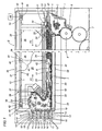
figure 1 illustrates a unit embodied in accordance with the present invention for supplying filters to a filter tip attachment machine, viewed schematically in a side elevation with certain parts shown in section and certain parts omitted; -
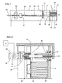
figure 2 shows a detail offigure 1 illustrated in a different embodiment, viewed schematically and in a side elevation; -
figure 3 is a cross sectional view showing the unit offigure 1 with certain parts omitted. - Referring to
figure 1 of the drawings, 1 denotes an infeed portion of a filter tip attachment machine, and 2 denotes a unit, in its entirety, forfeeding filters 3 to the aforementioned infeed portion 1; the unit 2 comprises a dispensinghopper 4 of which the outlet is coupled to the periphery of aroller 5 presenting a succession of axially oriented flutes or grooves, not illustrated, each able to accommodate arespective filter 3. - The
roller 5 is designed to advance thefilters 3 in succession along a direction transverse to their longitudinal axes and through acutting station 6, where each one is cut transversely in such a way as to generate a predetermined number (generally three) of double length filter plugs (not illustrated), that is to say filters twice the length of a filter tip associated with a single cigarette, before being conveyed by a train of rollers 7 toward a user station not shown in the drawings. - The unit 2 feeding the
filters 3 also comprises areceiving hopper 8 and a substantiallyhorizontal channel 9 by which thissame hopper 8 is connected to thedispensing hopper 4. Thereceiving hopper 8, which feeds into thechannel 9, is filled in its turn with filters by feed means denoted 10 in their entirety and, in the example offigure 1 , comprising threediverter devices 11 arranged in tiers and serving to redirect thefilters 3 from a longitudinal path of movement onto a transverse path. - In particular, each
diverter device 11 comprises afirst pair 12 and asecond pair 13 ofrollers 14, the tworollers 14 of eachpair channel 15 that extends from theupstream pair 12 through thedownstream pair 13 and emerges into thereceiving hopper 8. Filters turned out by a filter making machine (not illustrated) and advancing along a longitudinal path perpendicular to the viewing plane offigure 1 , are taken up by therollers 14 of thefirst pair 12 and diverted onto a path extending transversely to their longitudinal axes, passing along theaforementioned channel 15 between therollers 14 of thesecond pair 13 and into thereceiving hopper 8. - As illustrated in
figure 1 , the unit 2 comprises an inline storage facility orbuffer 16 of elongated geometry and variable volume, located above thefeed channel 9, interposed between thechannel 9 and thediverter devices 11 and extending from thereceiving hopper 8 to thedispensing hopper 4, of which the inlet end coincides substantially with thereceiving hopper 8. - The
feed channel 9 is delimited at the bottom by thetop branch 17 of ahorizontal conveyor 18 looped around two return pulleys denoted 19 and 20, located respectively at the upstream and downstream ends. Thedownstream pulley 20 is power driven by arelative motor 21, and the active surface of theconveyor 18 offered in contact to thefilters 3 presents atoothed profile 22. - The
variable volume buffer 16 is delimited at the bottom by a wall consisting in thetop branch 23 of aconveyor belt 24 looped at opposite ends around anupstream pulley 25 and adownstream pulley 26, the former coupled to amotor 27. - Associated rigidly with the
top branch 23 of thebelt 24 is the bottom end of a substantiallyvertical wall 28 rendered capable of movement, generated by themotor 27, between two limit positions of which the first, indicated in solid lines on the left as viewed infigure 1 , corresponds to a condition of minimum capacity afforded by thebuffer 16, and the second, indicated in phantom lines on the right as viewed infigure 1 , corresponds to a condition of maximum capacity afforded by thebuffer 16. It will be seen that in the condition of minimum capacity, themovable wall 28 functions as a side wall of thereceiving hopper 8. - The
bottom branch 29 of theconveyor belt 24 runs above thehorizontal channel 9 and is separated from the channel by awall 30 serving to disallow contact between thefilters 3 and the surface of thebelt 24. - The
receiving hopper 8 is equipped internally withsensors 31, serving to monitor and control the mass offilters 3 accumulating internally of thehopper 8, to which themotor 27 of theconveyor belt 24 is interlocked. More exactly, thesensors 31 are two in number, positioned in vertical alignment so that the lower of the two will sense a minimum replenishment value and the upper senses a maximum replenishment value for thehopper 8. - The
dispensing hopper 4 likewise is equipped withrespective means 32 by which to monitor and control the level of the mass offilters 3 accumulating internally of thehopper 4, to which themotor 21 of thelower conveyor 18 is interlocked.Such means 32 comprise ahinged flap 33 resting on the mass offilters 3, also asensor 34 connected to theflap 33 and capable of indicating its angular position as determined by the level of the mass offilters 3 internally of thedispensing hopper 4. - With reference to
figures 1 and3 , thebuffer 16 comprises twovertical side walls horizontal conveyor 18. The twoside walls figure 1 shows therear wall 35 and a part of thefront wall 36, combine with atop wall 37 cantilevered from aframe 38 to define a box-like structure containing the entire unit 2. - The unit 2 comprises means, denoted 39 in their entirety, serving to vary the distance between the
side walls rods 40 of which the ends are connected by way of respective lead screw andnut couplings 41 to the twoopposite walls - The
rods 40 project externally of thebuffer 16 on at least one side and are coupled via the respective ends toangle drive units 42 interconnected byline shafts 43. At least one of theangle drive units 42 is connected to a power drivenactuator 44 such as will set theangle drive units 42 andshafts 43 in motion and cause therods 40 to rotate about their respective axes in one direction or the other. - Thus, by causing the
rods 40 to turn on the relative lead screw/nut couplings 41, which present identical threads of opposite hand (one left, one right), the distance between theside walls filters 3. - In operation, starting for example from a situation with the
buffer 16 at minimum capacity, at the moment in which the mass offilters 3 in thereceiving hopper 8 exceeds a predetermined maximum value, thelevel sensors 31 will pilot themotor 27 and theconveyor belt 24 to translate themovable wall 28 toward thedispensing hopper 4 in the direction of the arrow denoted F1, thereby increasing the capacity of thebuffer 16. - Conversely, when the mass of
filters 3 in thereceiving hopper 8 drops below a minimum level, thesensors 31 will trigger the return of themovable wall 28 back toward thehopper 8, in the direction of the arrow denoted F2. - The
movable wall 28 thus provides means by which to vary the volume of thebuffer 16, whilst themotor 27 and therelative conveyor belt 24 provide means by which to set thewall 28 in motion. - The movement of the
horizontal conveyor 18 and its linear speed is controlled by themotor 21, which is interlocked in operation to thesensors 34 monitoring the angular movement of theflap 33. - In an alternative embodiment of the unit shown in
figure 2 , also described and illustrated inEuropean Patent 523,613 filters 3 are supplied to the unit 2 byfeed means 10 comprising at least onedevice 45 by which thefilters 3 are introduced axially. Thedevice 45 in question comprises anelongated body 46 extending between theside walls buffer 16 and centred on anaxis 47 perpendicular to thewalls elongated body 46 is insertable through an opening 48 in the wall denoted 36, located in a substantially central position relative to thereceiving hopper 8, and connected thus to one end of a cylindrical drum centred on theaforementioned axis 47. The drum in question, not visible infigure 2 but clearly described and illustrated inEP 523,613 cylindrical bushing 49 centred on theaxis 47 and associated rigidly with theside wall 36. The drum is rotatable as one with agear 50 aligned concentrically with theaxis 47 and in mesh with adriving gear 51 designed to set the drum and theelongated body 46 in rotation about theaxis 47 at a predetermined angular velocity. Theelongated body 46 presents a substantially cylindricalouter surface 52 of spiral cross-sectional outline, with alengthwise groove 53. Theelongated body 46 is of length substantially equal to the distance between the twoside walls axial bore 54 of which oneend 55, offered to therear side wall 35, is flared frustoconically. The drum is connected to one end of anaxial feed duct 56 through which thefilters 3 are carried toward the buffer, the other end of the duct being connected to aball joint 57 located downstream, relative to the direction along which thefilters 3 advance toward thereceiving hopper 8, of a pair ofrollers 58 by which the filters are taken up and directed along theduct 56. - In operation, the rotary motion of the drum internally of the
bushing 49 is accompanied by a rotation of theelongated body 46 about therelative axis 47 and a translational movement of theduct 56, downstream of theball joint 57, describing a cone denoted 59 infigure 2 . The rotation of theelongated body 46 within the mass offilters 3 occupying thehopper 8 has the effect of distancing thesesame filters 3 from theaxis 47 and creating a void that can be filled by thefilters 3 directed along theduct 56 by therollers 58.
Claims (10)
- A unit for feeding filters to a filter tip attachment machine, comprising feed means (10) by which filters (3) are introduced, a feed channel (9) along which the filters (3) are advanced, and connected to the outlet end of the channel (9), a dispensing hopper (4) from which the filters (3) are released to an infeed portion (1) of the filter tip attachment machine, an inline storage buffer (16) of variable volume, interposed between the feed means (10) and the feed channel (9) and delimited at the bottom by a wall consisting in the top branch (23) of a conveyor belt (24) looped at opposite ends around an upstream pulley (25) and a downstream pulley (26), the former coupled to a motor (27); associated rigidly with the top branch (23) of the belt (24) being a bottom end of a substantially vertical wall (28) rendered capable of movement, generated by the motor (27), between two limit positions of which the first corresponds to a condition of minimum capacity afforded by the buffer (16) and the second corresponds to a condition of maximum capacity afforded by the buffer (16), characterized in that the variable volume buffer (16) presents two side walls (35, 36) disposed mutually parallel and substantially perpendicular to the bottom wall, and is equipped with means (39) by which to vary the distance between the two side walls (35, 36), so as to allow of changing the transverse dimension of the variable volume buffer (16).
- A unit as in claim 1, comprising: a receiving hopper (8) associated with the feed means (10) by which the filters (3) are introduced and supplying the feed channel (9); means (31) associated with the receiving hopper (8) and serving to monitor and control the level of the mass of filters (3) occupying the selfsame hopper; and means (39) serving to vary the volume of the variable volume buffer (16), interlocked to the means (31) for monitoring and controlling the level of the mass of filters (3).
- A unit as in claim 2, wherein the variable volume buffer (16) presents an infeed section associated with the receiving hopper (8), and the volume of the buffer (16) is varied by means (39) comprising a wall (28) capable of movement generated by respective drive means (23, 24, 27) between a first limit position corresponding to the minimum capacity of the variable volume buffer (16), in which it functions as a wall of the receiving hopper (8), and a second limit position corresponding to the maximum capacity of the buffer (16).
- A unit as in claim 3, wherein the variable volume buffer (16) is of elongated appearance, extending above and parallel to the feed channel (9) along which the filters (3) advance, and delimited on the underside by a bottom wall extending transversely to the movable wall (28).
- A unit as in claim 4, wherein the bottom wall is provided by the drive means (23, 24) operating the movable wall (28).
- A unit as in claim 5, wherein the bottom wall is rigidly associated with the movable wall (28) and consists in the top branch (23) of a conveyor belt (24) associated with a motor (27).
- A unit as in claims 1 to 6, wherein the feed channel (9) along which the filters (3) advance comprises a conveyor belt (18) extending beneath and parallel to the drive means (23, 24, 27) of the movable wall (28) and associated with respective further drive means (21).
- A unit as in claim 7, wherein the dispensing hopper (4) comprises respective means (32, 33, 34) serving to monitor and control the level of the mass of filters (3) occupying the selfsame hopper (4), to which the drive means (21) of the conveyor belt (18) are interlocked.
- A unit as in claims 1 wherein the feed means (10) introducing the filters (3) comprise at least one diverter device (11) by which the filters (3) are directed transversely to their axes into the receiving hopper (8).
- A unit as in claims 1 wherein the feed means (10) introducing the filters (3) comprise at least one device (45) by which the filters (3) are directed axially into the receiving hopper (8)).
Applications Claiming Priority (3)
| Application Number | Priority Date | Filing Date | Title |
|---|---|---|---|
| ITBO20030151 | 2003-03-20 | ||
| IT000151A ITBO20030151A1 (en) | 2003-03-20 | 2003-03-20 | UNIT FOR FEEDING FILTERS TO A FILTER FEEDER MACHINE. |
| PCT/IB2004/000824 WO2004082410A1 (en) | 2003-03-20 | 2004-03-11 | A unit for feeding filters to a filter tip attachment machine |
Publications (2)
| Publication Number | Publication Date |
|---|---|
| EP1603416A1 EP1603416A1 (en) | 2005-12-14 |
| EP1603416B1 true EP1603416B1 (en) | 2008-05-14 |
Family
ID=33017950
Family Applications (1)
| Application Number | Title | Priority Date | Filing Date |
|---|---|---|---|
| EP04719547A Expired - Lifetime EP1603416B1 (en) | 2003-03-20 | 2004-03-11 | A unit for feeding filters to a filter tip attachment machine |
Country Status (8)
| Country | Link |
|---|---|
| US (1) | US7640935B2 (en) |
| EP (1) | EP1603416B1 (en) |
| JP (1) | JP4464392B2 (en) |
| CN (1) | CN100473295C (en) |
| AT (1) | ATE394947T1 (en) |
| DE (1) | DE602004013738D1 (en) |
| IT (1) | ITBO20030151A1 (en) |
| WO (1) | WO2004082410A1 (en) |
Cited By (2)
| Publication number | Priority date | Publication date | Assignee | Title |
|---|---|---|---|---|
| EP2260732A1 (en) | 2009-06-13 | 2010-12-15 | Hauni Maschinenbau AG | Device and method for consecutive emptying of containers filled with rod-shaped products |
| CN107280066A (en) * | 2015-10-16 | 2017-10-24 | 王华伟 | A kind of granular material packing device |
Families Citing this family (6)
| Publication number | Priority date | Publication date | Assignee | Title |
|---|---|---|---|---|
| DE102007030049B4 (en) * | 2007-06-26 | 2009-10-08 | Hauni Maschinenbau Ag | A method of controlling a flow of conveyance formed between articles of the tobacco processing industry between a tray unloader and a sending device having a plurality of sending modules |
| PL210818B1 (en) * | 2008-05-16 | 2012-03-30 | Int Tobacco Machinery Poland | Storage and transport system for longitudinal rod-like elements, as well as the method to control of the mass flow as well as filling and emptying of the storage and transport system for longitudinal rod-like elements |
| DE102011088357A1 (en) * | 2011-12-13 | 2013-06-13 | Hauni Maschinenbau Ag | Conveying device for conveying rod-shaped articles of the tobacco-processing industry |
| DE102016107248A1 (en) * | 2016-04-19 | 2017-10-19 | Hauni Maschinenbau Gmbh | A container for receiving or dispensing portions of a product mass flow formed from rod-shaped articles of the tobacco processing industry, as well as an arrangement for discretizing or forming a product mass flow with such containers |
| DE102020111946B4 (en) * | 2020-05-04 | 2023-01-26 | Körber Technologies Gmbh | Conveyor drum in the tobacco processing industry |
| DE102020119923A1 (en) * | 2020-07-28 | 2022-02-03 | Hauni Maschinenbau Gmbh | Storage device and method for filling a storage device |
Family Cites Families (9)
| Publication number | Priority date | Publication date | Assignee | Title |
|---|---|---|---|---|
| US5220992A (en) | 1976-04-13 | 1993-06-22 | Molins Limited | Apparatus for conveying rods of the cigarette industry |
| US4042094A (en) * | 1976-05-24 | 1977-08-16 | Alfred Schmermund | Conveying and storing apparatus |
| US4222477A (en) * | 1977-10-27 | 1980-09-16 | Molins Limited | Reservoir for cigarettes and like articles |
| DE2758863A1 (en) | 1977-12-30 | 1979-07-12 | Hauni Werke Koerber & Co Kg | STORAGE DEVICE FOR CIGARETTES OR OTHER ROD-SHAPED ARTICLES |
| IT1199043B (en) * | 1982-12-03 | 1988-12-21 | Sasib Spa | METHOD AND DEVICE FOR THE AUTOMATIC CONTROL OF THE REVERSIBLE MOVEMENT CAPACITY ELEMENT OF THE LUNG STORES ASSOCIATED WITH A CIGARETTES OR SIMILAR SUPPLY SYSTEM |
| US4580939A (en) * | 1983-09-01 | 1986-04-08 | Molins Machine Company Inc. | Feeding device for cigarette filters and similar rods |
| IT1242139B (en) | 1989-09-20 | 1994-02-16 | Molins Plc | VARIABLE VOLUME TANK FOR OBJECTS OF ELONGATED FORM, IN PARTICULAR CIGARETTES |
| IT1252438B (en) | 1991-07-19 | 1995-06-14 | Gd Spa | DEVICE FOR FEEDING FILTERS TO A FILTER FEEDER MACHINE |
| DE10154746A1 (en) | 2001-11-09 | 2003-05-28 | Hauni Maschinenbau Ag | Magazine for rod-shaped articles in the tobacco processing industry, especially filter rods |
-
2003
- 2003-03-20 IT IT000151A patent/ITBO20030151A1/en unknown
-
2004
- 2004-03-11 WO PCT/IB2004/000824 patent/WO2004082410A1/en not_active Ceased
- 2004-03-11 DE DE602004013738T patent/DE602004013738D1/en not_active Expired - Lifetime
- 2004-03-11 US US10/549,513 patent/US7640935B2/en not_active Expired - Fee Related
- 2004-03-11 JP JP2006506362A patent/JP4464392B2/en not_active Expired - Fee Related
- 2004-03-11 AT AT04719547T patent/ATE394947T1/en not_active IP Right Cessation
- 2004-03-11 CN CNB2004800070032A patent/CN100473295C/en not_active Expired - Fee Related
- 2004-03-11 EP EP04719547A patent/EP1603416B1/en not_active Expired - Lifetime
Cited By (3)
| Publication number | Priority date | Publication date | Assignee | Title |
|---|---|---|---|---|
| EP2260732A1 (en) | 2009-06-13 | 2010-12-15 | Hauni Maschinenbau AG | Device and method for consecutive emptying of containers filled with rod-shaped products |
| DE102009025568A1 (en) | 2009-06-13 | 2010-12-16 | Hauni Maschinenbau Ag | Device and method for the successive emptying of containers filled with rod-shaped products |
| CN107280066A (en) * | 2015-10-16 | 2017-10-24 | 王华伟 | A kind of granular material packing device |
Also Published As
| Publication number | Publication date |
|---|---|
| CN100473295C (en) | 2009-04-01 |
| ATE394947T1 (en) | 2008-05-15 |
| CN1761411A (en) | 2006-04-19 |
| US20060196514A1 (en) | 2006-09-07 |
| EP1603416A1 (en) | 2005-12-14 |
| JP2006520596A (en) | 2006-09-14 |
| WO2004082410A1 (en) | 2004-09-30 |
| ITBO20030151A1 (en) | 2004-09-21 |
| US7640935B2 (en) | 2010-01-05 |
| DE602004013738D1 (en) | 2008-06-26 |
| JP4464392B2 (en) | 2010-05-19 |
Similar Documents
| Publication | Publication Date | Title |
|---|---|---|
| US8992400B2 (en) | Machine and method for manufacturing composite filters | |
| USRE28383E (en) | Transfer apparatus for rod-shaped articles | |
| US7640935B2 (en) | Unit for feeding filters to a filter tip attachment machine | |
| US4893640A (en) | Multiple-rod cigarette making machine | |
| US6443160B1 (en) | Method and device for forming a cigarette rod containing an additive material | |
| GB2068325A (en) | Apparatus for replenishing the supplies of filter rod sections in the magazines of filter tipping machines | |
| US4555011A (en) | Conveying rod-like articles | |
| US6016904A (en) | Reservoir system for rod-like articles | |
| US4372710A (en) | Apparatus for manipulating filter rod sections or the like between producing and processing machines | |
| EP0523613B1 (en) | Device for feeding filters to a filter assembly machine | |
| US6782889B2 (en) | Apparatus for manipulating tows of filamentary material | |
| US4551040A (en) | Apparatus for transporting rod-shaped articles between the discharge ends of pneumatic conveyor pipes and a processing machine | |
| CN102595941B (en) | Feeder system for rod components of tobacco products, and associated method | |
| US4522295A (en) | Device for dividing a stream of loose material | |
| GB2153653A (en) | Apparatus for changing the direction of transport of rod-shaped articles | |
| GB954481A (en) | Improvements in or relating to apparatus for feeding stubs | |
| CN219729868U (en) | Bar stock distributing mechanism | |
| US12439953B2 (en) | Machine for wrapping a smokable material in a wrapper, a feeding device for the machine, and a smokable product therefrom | |
| GB2124174A (en) | Conveying rod-like articles | |
| ITBO930357A1 (en) | COMBINED PACKAGING-FILTER FEEDER UNIT FOR THE CREATION OF CIGARETTES WITH FILTER. | |
| CN207497064U (en) | A kind of medicine plate automatic blanking device | |
| CN110432542B (en) | Multi-element material combined process system | |
| US3398751A (en) | Apparatus for feeding particulate material and forming rod therefrom | |
| US3398752A (en) | Apparatus for feeding particulate material and forming rod therefrom | |
| EP1457122B1 (en) | A tobacco feeder unit in a cigarette maker |
Legal Events
| Date | Code | Title | Description |
|---|---|---|---|
| PUAI | Public reference made under article 153(3) epc to a published international application that has entered the european phase |
Free format text: ORIGINAL CODE: 0009012 |
|
| 17P | Request for examination filed |
Effective date: 20050928 |
|
| AK | Designated contracting states |
Kind code of ref document: A1 Designated state(s): AT BE BG CH CY CZ DE DK EE ES FI FR GB GR HU IE IT LI LU MC NL PL PT RO SE SI SK TR |
|
| AX | Request for extension of the european patent |
Extension state: AL LT LV MK |
|
| DAX | Request for extension of the european patent (deleted) | ||
| 17Q | First examination report despatched |
Effective date: 20070308 |
|
| GRAP | Despatch of communication of intention to grant a patent |
Free format text: ORIGINAL CODE: EPIDOSNIGR1 |
|
| GRAS | Grant fee paid |
Free format text: ORIGINAL CODE: EPIDOSNIGR3 |
|
| GRAA | (expected) grant |
Free format text: ORIGINAL CODE: 0009210 |
|
| AK | Designated contracting states |
Kind code of ref document: B1 Designated state(s): AT BE BG CH CY CZ DE DK EE ES FI FR GB GR HU IE IT LI LU MC NL PL PT RO SE SI SK TR |
|
| REG | Reference to a national code |
Ref country code: GB Ref legal event code: FG4D |
|
| REG | Reference to a national code |
Ref country code: CH Ref legal event code: EP |
|
| REG | Reference to a national code |
Ref country code: IE Ref legal event code: FG4D Free format text: LANGUAGE OF EP DOCUMENT: FRENCH |
|
| REG | Reference to a national code |
Ref country code: CH Ref legal event code: NV Representative=s name: BUGNION S.A. |
|
| REF | Corresponds to: |
Ref document number: 602004013738 Country of ref document: DE Date of ref document: 20080626 Kind code of ref document: P |
|
| PG25 | Lapsed in a contracting state [announced via postgrant information from national office to epo] |
Ref country code: SI Free format text: LAPSE BECAUSE OF FAILURE TO SUBMIT A TRANSLATION OF THE DESCRIPTION OR TO PAY THE FEE WITHIN THE PRESCRIBED TIME-LIMIT Effective date: 20080514 |
|
| PG25 | Lapsed in a contracting state [announced via postgrant information from national office to epo] |
Ref country code: ES Free format text: LAPSE BECAUSE OF FAILURE TO SUBMIT A TRANSLATION OF THE DESCRIPTION OR TO PAY THE FEE WITHIN THE PRESCRIBED TIME-LIMIT Effective date: 20080825 Ref country code: FI Free format text: LAPSE BECAUSE OF FAILURE TO SUBMIT A TRANSLATION OF THE DESCRIPTION OR TO PAY THE FEE WITHIN THE PRESCRIBED TIME-LIMIT Effective date: 20080514 |
|
| NLV1 | Nl: lapsed or annulled due to failure to fulfill the requirements of art. 29p and 29m of the patents act | ||
| PG25 | Lapsed in a contracting state [announced via postgrant information from national office to epo] |
Ref country code: NL Free format text: LAPSE BECAUSE OF FAILURE TO SUBMIT A TRANSLATION OF THE DESCRIPTION OR TO PAY THE FEE WITHIN THE PRESCRIBED TIME-LIMIT Effective date: 20080514 Ref country code: PL Free format text: LAPSE BECAUSE OF FAILURE TO SUBMIT A TRANSLATION OF THE DESCRIPTION OR TO PAY THE FEE WITHIN THE PRESCRIBED TIME-LIMIT Effective date: 20080514 Ref country code: AT Free format text: LAPSE BECAUSE OF FAILURE TO SUBMIT A TRANSLATION OF THE DESCRIPTION OR TO PAY THE FEE WITHIN THE PRESCRIBED TIME-LIMIT Effective date: 20080514 |
|
| PG25 | Lapsed in a contracting state [announced via postgrant information from national office to epo] |
Ref country code: SE Free format text: LAPSE BECAUSE OF FAILURE TO SUBMIT A TRANSLATION OF THE DESCRIPTION OR TO PAY THE FEE WITHIN THE PRESCRIBED TIME-LIMIT Effective date: 20080814 Ref country code: CZ Free format text: LAPSE BECAUSE OF FAILURE TO SUBMIT A TRANSLATION OF THE DESCRIPTION OR TO PAY THE FEE WITHIN THE PRESCRIBED TIME-LIMIT Effective date: 20080514 Ref country code: PT Free format text: LAPSE BECAUSE OF FAILURE TO SUBMIT A TRANSLATION OF THE DESCRIPTION OR TO PAY THE FEE WITHIN THE PRESCRIBED TIME-LIMIT Effective date: 20081014 Ref country code: DK Free format text: LAPSE BECAUSE OF FAILURE TO SUBMIT A TRANSLATION OF THE DESCRIPTION OR TO PAY THE FEE WITHIN THE PRESCRIBED TIME-LIMIT Effective date: 20080514 |
|
| PG25 | Lapsed in a contracting state [announced via postgrant information from national office to epo] |
Ref country code: SK Free format text: LAPSE BECAUSE OF FAILURE TO SUBMIT A TRANSLATION OF THE DESCRIPTION OR TO PAY THE FEE WITHIN THE PRESCRIBED TIME-LIMIT Effective date: 20080514 Ref country code: RO Free format text: LAPSE BECAUSE OF FAILURE TO SUBMIT A TRANSLATION OF THE DESCRIPTION OR TO PAY THE FEE WITHIN THE PRESCRIBED TIME-LIMIT Effective date: 20080514 Ref country code: BE Free format text: LAPSE BECAUSE OF FAILURE TO SUBMIT A TRANSLATION OF THE DESCRIPTION OR TO PAY THE FEE WITHIN THE PRESCRIBED TIME-LIMIT Effective date: 20080514 |
|
| PLBE | No opposition filed within time limit |
Free format text: ORIGINAL CODE: 0009261 |
|
| STAA | Information on the status of an ep patent application or granted ep patent |
Free format text: STATUS: NO OPPOSITION FILED WITHIN TIME LIMIT |
|
| 26N | No opposition filed |
Effective date: 20090217 |
|
| PG25 | Lapsed in a contracting state [announced via postgrant information from national office to epo] |
Ref country code: EE Free format text: LAPSE BECAUSE OF FAILURE TO SUBMIT A TRANSLATION OF THE DESCRIPTION OR TO PAY THE FEE WITHIN THE PRESCRIBED TIME-LIMIT Effective date: 20080514 Ref country code: BG Free format text: LAPSE BECAUSE OF FAILURE TO SUBMIT A TRANSLATION OF THE DESCRIPTION OR TO PAY THE FEE WITHIN THE PRESCRIBED TIME-LIMIT Effective date: 20080814 |
|
| PG25 | Lapsed in a contracting state [announced via postgrant information from national office to epo] |
Ref country code: IT Free format text: LAPSE BECAUSE OF FAILURE TO SUBMIT A TRANSLATION OF THE DESCRIPTION OR TO PAY THE FEE WITHIN THE PRESCRIBED TIME-LIMIT Effective date: 20080514 |
|
| PG25 | Lapsed in a contracting state [announced via postgrant information from national office to epo] |
Ref country code: MC Free format text: LAPSE BECAUSE OF NON-PAYMENT OF DUE FEES Effective date: 20090331 |
|
| REG | Reference to a national code |
Ref country code: FR Ref legal event code: ST Effective date: 20091130 |
|
| REG | Reference to a national code |
Ref country code: IE Ref legal event code: MM4A |
|
| PG25 | Lapsed in a contracting state [announced via postgrant information from national office to epo] |
Ref country code: IE Free format text: LAPSE BECAUSE OF NON-PAYMENT OF DUE FEES Effective date: 20090311 |
|
| PG25 | Lapsed in a contracting state [announced via postgrant information from national office to epo] |
Ref country code: FR Free format text: LAPSE BECAUSE OF NON-PAYMENT OF DUE FEES Effective date: 20091123 |
|
| PGFP | Annual fee paid to national office [announced via postgrant information from national office to epo] |
Ref country code: CH Payment date: 20100325 Year of fee payment: 7 |
|
| PGFP | Annual fee paid to national office [announced via postgrant information from national office to epo] |
Ref country code: GB Payment date: 20100326 Year of fee payment: 7 |
|
| PG25 | Lapsed in a contracting state [announced via postgrant information from national office to epo] |
Ref country code: GR Free format text: LAPSE BECAUSE OF FAILURE TO SUBMIT A TRANSLATION OF THE DESCRIPTION OR TO PAY THE FEE WITHIN THE PRESCRIBED TIME-LIMIT Effective date: 20080815 |
|
| PG25 | Lapsed in a contracting state [announced via postgrant information from national office to epo] |
Ref country code: LU Free format text: LAPSE BECAUSE OF NON-PAYMENT OF DUE FEES Effective date: 20090311 |
|
| PG25 | Lapsed in a contracting state [announced via postgrant information from national office to epo] |
Ref country code: HU Free format text: LAPSE BECAUSE OF FAILURE TO SUBMIT A TRANSLATION OF THE DESCRIPTION OR TO PAY THE FEE WITHIN THE PRESCRIBED TIME-LIMIT Effective date: 20081115 |
|
| PG25 | Lapsed in a contracting state [announced via postgrant information from national office to epo] |
Ref country code: CY Free format text: LAPSE BECAUSE OF FAILURE TO SUBMIT A TRANSLATION OF THE DESCRIPTION OR TO PAY THE FEE WITHIN THE PRESCRIBED TIME-LIMIT Effective date: 20080514 |
|
| REG | Reference to a national code |
Ref country code: CH Ref legal event code: PL |
|
| GBPC | Gb: european patent ceased through non-payment of renewal fee |
Effective date: 20110311 |
|
| PG25 | Lapsed in a contracting state [announced via postgrant information from national office to epo] |
Ref country code: LI Free format text: LAPSE BECAUSE OF NON-PAYMENT OF DUE FEES Effective date: 20110331 Ref country code: CH Free format text: LAPSE BECAUSE OF NON-PAYMENT OF DUE FEES Effective date: 20110331 |
|
| PG25 | Lapsed in a contracting state [announced via postgrant information from national office to epo] |
Ref country code: GB Free format text: LAPSE BECAUSE OF NON-PAYMENT OF DUE FEES Effective date: 20110311 |
|
| PGFP | Annual fee paid to national office [announced via postgrant information from national office to epo] |
Ref country code: TR Payment date: 20140224 Year of fee payment: 11 |
|
| PG25 | Lapsed in a contracting state [announced via postgrant information from national office to epo] |
Ref country code: TR Free format text: LAPSE BECAUSE OF NON-PAYMENT OF DUE FEES Effective date: 20150311 |
|
| PGFP | Annual fee paid to national office [announced via postgrant information from national office to epo] |
Ref country code: DE Payment date: 20210329 Year of fee payment: 18 |
|
| REG | Reference to a national code |
Ref country code: DE Ref legal event code: R119 Ref document number: 602004013738 Country of ref document: DE |
|
| PG25 | Lapsed in a contracting state [announced via postgrant information from national office to epo] |
Ref country code: DE Free format text: LAPSE BECAUSE OF NON-PAYMENT OF DUE FEES Effective date: 20221001 |