EP1605128B1 - Revolving door - Google Patents
Revolving door Download PDFInfo
- Publication number
- EP1605128B1 EP1605128B1 EP05076306.9A EP05076306A EP1605128B1 EP 1605128 B1 EP1605128 B1 EP 1605128B1 EP 05076306 A EP05076306 A EP 05076306A EP 1605128 B1 EP1605128 B1 EP 1605128B1
- Authority
- EP
- European Patent Office
- Prior art keywords
- roof construction
- revolving door
- girders
- cylindrical wall
- door
- Prior art date
- Legal status (The legal status is an assumption and is not a legal conclusion. Google has not performed a legal analysis and makes no representation as to the accuracy of the status listed.)
- Expired - Lifetime
Links
Images
Classifications
-
- E—FIXED CONSTRUCTIONS
- E06—DOORS, WINDOWS, SHUTTERS, OR ROLLER BLINDS IN GENERAL; LADDERS
- E06B—FIXED OR MOVABLE CLOSURES FOR OPENINGS IN BUILDINGS, VEHICLES, FENCES OR LIKE ENCLOSURES IN GENERAL, e.g. DOORS, WINDOWS, BLINDS, GATES
- E06B3/00—Window sashes, door leaves, or like elements for closing wall or like openings; Layout of fixed or moving closures, e.g. windows in wall or like openings; Features of rigidly-mounted outer frames relating to the mounting of wing frames
- E06B3/90—Revolving doors; Cages or housings therefor
Definitions
- the invention relates to a revolving door comprising a cylindrical wall, and placed above the cylindrical wall a roof construction, with at least one rotatable door leaf being disposed within the cylindrical wall and below the roof construction, wherein the cylindrical wall is provided with passage openings.
- a revolving door comprising a cylindrical wall and a roof construction disposed above the cylindrical wall, having a connecting element placed in the centre of the door and girders extending radially therefrom, with at least one rotatable door leaf being suspended from the roof construction within the cylindrical wall and below the roof construction, while the cylindrical wall is provided with passage openings.
- the known revolving door has the drawback that it is endowed with little flexibility. This may be illustrated as follows.
- the life span of a revolving is approximately twelve years, while the building in which the same is employed will often not stand more than 30 years. On average, the function of the building changes once every four years. This means that within the life span of the known revolving door, the demands with respect to the revolving door's functionality may change three times. For example, when a supermarket is housed in the building, a three-leafed revolving door is needed in order to allow the pulsed passage of customers with shopping trolleys. A builder's merchant, on the other hand, would rather use a two-leafed revolving door in combination with sliding doors.
- the present invention is also aimed at the realisation of a fast starting time and stopping time of the revolving door, in connection with the safety requirements concerning the person passing through the revolving door.
- the revolving door is characterized in that the girders are placed under pre-tension, in order to create an upward force on the connecting element.
- the roof construction even in the case of the revolving door having a large diameter, is able to meet the practical requirements with respect to the allowable roof load, which is approximately 1000 N/m 2 .
- the door leaf or door leaves may then be as light as possible in order for the revolving door to be able to realise a fast starting and stopping time.
- the revolving door according to the invention is characterized in that the roof construction comprises a rail and that the at least one door leaf has at the topside at least one roller that is accommodated in the rail, and by which the door leaf is suspended from the roof construction.
- the suspension of the at least one door leaf can at the same time serve for its propulsion, in particular in the embodiment that is characterized in that the at least one roller is provided with a motor drive.
- the revolving door is characterized in that the same possesses posts on which the roof construction is placed. This affords the designer of the revolving door a vast degree of freedom, while the door can be completed independently of the architect who has designed the building in which the revolving door is going to be used.
- the positioning of the posts is also flexible; only the area of the passage openings must remain free of posts.
- a first preferred embodiment to realise one thing and another is characterized in that the posts are positioned at the cylindrical wall and support ends of cross girders, and that the radially extending girders of the roof construction rest on said cross girders, with the rail being suspended via tension rods from ends of these girders located near the cylindrical wall.
- a second preferred embodiment to realise this is characterized in that the rail of the roof construction rests on the posts, and that ends of the radially extending girders of the roof construction at the cylindrical wall side also rest on these posts, with the girders being provided with tension rods to allow a tensile load to be exerted on the underside of the girders.
- the revolving door may be embodied such that the at least one door leaf is removable and replaceable.
- replacing the door wings it is, for example, possible to change to a number of door leaves that differs from the original number, e.g. two, three, four or even more than four door leaves, all in accordance with the requirements at that moment. It is further in general possible to largely standardise the production of various types of revolving doors. This will be explained below.
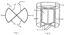
- a revolving door 1 is shown possessing a cylindrical wall 2 and a roof construction 3 (see Figure 2 ) placed above the cylindrical wall 2.
- the cylindrical wall 2 of the revolving door 1 also comprises passage openings 5 and 6 allowing users to pass through the revolving door 1.
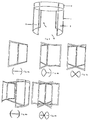
- Figure 3 shows the same components that have just been elucidated by way of Figure 2 .
- the revolving door 1 as shown in Figure 3 is used in combination with at least one door leaf as shown in Figure 4a , which is suspended from the roof construction 3.
- FIGS. 4b and 4c show a three-leafed and four-leafed element, respectively, that within the cylindrical wall 2 can be suspended from the roof construction 3 to comply with the practical need and the circumstances in which the revolving door 1 will have to be employed.
- Figure 4d and Figure 4e show some possible further variations that together with the construction shown in Figure 3 may provide a revolving door according to and within the scope of the invention. It will be apparent, that the cylindrical wall 2 and the roof construction 3 together form a module, which allows a largely standardised production of the desired embodiment of the revolving door 1 according to the invention. In addition, one man is well able to install the door.
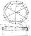
- Figure 6 shows that the roof construction 3 possesses a rail 7 and that the at least one door leaf 4 has at the top side at least one, and in the case shown, two rollers 8 that are accommodated in the rail 7, and by which the door leaf 4 is suspended from the roof construction 3.
- At least one roller 8 is provided with a motor drive. If one single door leaf is employed, it is for consideration of symmetry desirable to use two rollers 8, and both to be provided with a motor drive. The person skilled in the art is quite familiar with the manner in which one thing and another needs to be carried out, so that a further explanation is not necessary.
- the roof construction 3 is founded in, for example, the construction of the building in which the revolving door is employed.
- FIGS 5 and 6 show a different way for the roof construction 3 to be self-supporting, namely an embodiment in which posts 9 (see Figure 5 ) are used upon which the roof construction 3 is placed.
- the roof construction 3 possesses a connecting element 10 placed in the centre of the revolving door, to which girders 11 radially extending therefrom are coupled. These girders 11 are placed under pre-tension in order to realise an upward force on the connecting element 10.
- cross girders 12 rest on posts 9 positioned at the cylindrical wall 2, such that these cross girders 12, as it were, form chords within a circumferential circle formed by the cylindrical wall 2.
- On these cross girders 12 rest the radially extending girders 11 of the roof construction 3 (see Figure 5 ), while, and this is clearly shown in Figure 6 , via tension rods 13 the rail 7 of the roof construction 3 is suspended from these girders 11 located at the cylindrical wall 2.
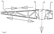
- a possible second and third embodiment for realising that the connecting element 10 of the roof construction 3 undergoes an upward force is schematically illustrated in the Figures 7 and 8 .
- Figure 7 shows the second embodiment of the girders 11 for placing these under pre-tension, in order to realise an upward force on the connecting element 10.
- Figure 7 shows that to this end, the girders 11 may at their underside be provided with a tension rod 14, to allow these girders 11 at their underside to be pulled in the direction of the connecting element 10.
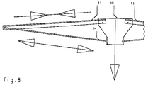
- FIG 8 shows a third embodiment wherein a tension rod 14 is used, which extends between the connecting element 10 and the end of the girder 11 that faces away from the connecting element 10. This latter end, as mentioned above, as well as the corresponding end of girder 11 shown in Figure 7 , also rests on a post on which also the roof construction and in particular its rail rest.
Landscapes
- Engineering & Computer Science (AREA)
- Civil Engineering (AREA)
- Structural Engineering (AREA)
- Extensible Doors And Revolving Doors (AREA)
Description
- The invention relates to a revolving door comprising a cylindrical wall, and placed above the cylindrical wall a roof construction, with at least one rotatable door leaf being disposed within the cylindrical wall and below the roof construction, wherein the cylindrical wall is provided with passage openings.
- Applicant has had such a revolving door on the market for many years now, and it is also known, for example, from the British patent application
GB-A-2 052 612 - From
GB-A-2 131 073 - The known revolving door has the drawback that it is endowed with little flexibility. This may be illustrated as follows. The life span of a revolving is approximately twelve years, while the building in which the same is employed will often not stand more than 30 years. On average, the function of the building changes once every four years. This means that within the life span of the known revolving door, the demands with respect to the revolving door's functionality may change three times. For example, when a supermarket is housed in the building, a three-leafed revolving door is needed in order to allow the pulsed passage of customers with shopping trolleys. A builder's merchant, on the other hand, would rather use a two-leafed revolving door in combination with sliding doors. The underlying reason being the large segments that this door has and that render this door suitable for the trolleys carrying gypsum plates as sold at a builder's merchant. In such a case it is also desirable for the revolving door to be embodied without a central column.
- Apart from the objective of flexibility as explained in the foregoing, the present invention is also aimed at the realisation of a fast starting time and stopping time of the revolving door, in connection with the safety requirements concerning the person passing through the revolving door.
- These and other objectives that will become apparent from the following are realised with a revolving door that is characterized by one or several of the appended claims.
- In a first aspect of the invention, the revolving door is characterized in that the girders are placed under pre-tension, in order to create an upward force on the connecting element. This achieves among other things, that the roof construction, even in the case of the revolving door having a large diameter, is able to meet the practical requirements with respect to the allowable roof load, which is approximately 1000 N/m2. The door leaf or door leaves may then be as light as possible in order for the revolving door to be able to realise a fast starting and stopping time.
- In another aspect, the revolving door according to the invention is characterized in that the roof construction comprises a rail and that the at least one door leaf has at the topside at least one roller that is accommodated in the rail, and by which the door leaf is suspended from the roof construction. In this manner, the suspension of the at least one door leaf can at the same time serve for its propulsion, in particular in the embodiment that is characterized in that the at least one roller is provided with a motor drive.
- In a preferred embodiment, the revolving door is characterized in that the same possesses posts on which the roof construction is placed. This affords the designer of the revolving door a vast degree of freedom, while the door can be completed independently of the architect who has designed the building in which the revolving door is going to be used. The positioning of the posts is also flexible; only the area of the passage openings must remain free of posts.
- A first preferred embodiment to realise one thing and another, is characterized in that the posts are positioned at the cylindrical wall and support ends of cross girders, and that the radially extending girders of the roof construction rest on said cross girders, with the rail being suspended via tension rods from ends of these girders located near the cylindrical wall.
- A second preferred embodiment to realise this is characterized in that the rail of the roof construction rests on the posts, and that ends of the radially extending girders of the roof construction at the cylindrical wall side also rest on these posts, with the girders being provided with tension rods to allow a tensile load to be exerted on the underside of the girders.
- Furthermore, the revolving door may be embodied such that the at least one door leaf is removable and replaceable. This fulfils the practical need of a great degree of flexibility, as explained in the foregoing. When replacing the door wings it is, for example, possible to change to a number of door leaves that differs from the original number, e.g. two, three, four or even more than four door leaves, all in accordance with the requirements at that moment. It is further in general possible to largely standardise the production of various types of revolving doors. This will be explained below.
- In the case of the revolving door according to the invention having very large diameters, it may be desirable to embody the door such that the roof construction is founded in the structure of a building.
- Hereinbelow the invention will be further elucidated by way of some exemplary embodiments that do not limit the claims, and with reference to the drawing. The drawing shows in:
-
Figure 1 , a cross section of the revolving door according to the invention shown inFigure 2 ; -
Figure 2 , a three dimensional view of the revolving door according to the invention; -
Figure 3 , a cylindrical wall and roof construction of the revolving door according to the invention; -
Figures 4a to 4e , several types of door leaves that can be used in combination with the cylindrical wall and roof construction of the revolving door according to the invention shown inFigure 3 ; -
Figures 5 and 6 , a top view and mid-sectional view of a first embodiment of the revolving door according to the invention; -
Figure 7 , a second embodiment of a portion of the roof construction of the revolving door according to the invention; and -
Figure 8 , a third embodiment of a portion of the roof construction of the revolving door according to the invention. - Identical reference numerals used in the figures refer to similar components.
- With reference first to
Figure 1 and Figure 2 , a revolvingdoor 1 is shown possessing acylindrical wall 2 and a roof construction 3 (seeFigure 2 ) placed above thecylindrical wall 2. - Within the
cylindrical wall 2 and underneath theroof construction 3, the case illustrated inFigures 1 and 2 shows 4 rotatably disposeddoor leaves 4. Thecylindrical wall 2 of the revolvingdoor 1 also comprisespassage openings 5 and 6 allowing users to pass through the revolvingdoor 1. - With the exception of the
door leaves 4,Figure 3 shows the same components that have just been elucidated by way ofFigure 2 . - In accordance with the invention, the revolving
door 1 as shown inFigure 3 is used in combination with at least one door leaf as shown inFigure 4a , which is suspended from theroof construction 3. - The special feature of the revolving
door 1 according to the invention is, that it allows the revolvingdoor 1 to be adapted in a flexible manner to the requirements of use.Figures 4b and 4c show a three-leafed and four-leafed element, respectively, that within thecylindrical wall 2 can be suspended from theroof construction 3 to comply with the practical need and the circumstances in which the revolvingdoor 1 will have to be employed. -
Figure 4d and Figure 4e show some possible further variations that together with the construction shown inFigure 3 may provide a revolving door according to and within the scope of the invention. It will be apparent, that thecylindrical wall 2 and theroof construction 3 together form a module, which allows a largely standardised production of the desired embodiment of the revolvingdoor 1 according to the invention. In addition, one man is well able to install the door. - In order to further elucidate the removable suspension of the at least one door leaf, reference is now made to
Figure 5 and Figure 6 . -
Figure 6 shows that theroof construction 3 possesses arail 7 and that the at least onedoor leaf 4 has at the top side at least one, and in the case shown, two rollers 8 that are accommodated in therail 7, and by which thedoor leaf 4 is suspended from theroof construction 3. - Preferably at least one roller 8 is provided with a motor drive. If one single door leaf is employed, it is for consideration of symmetry desirable to use two rollers 8, and both to be provided with a motor drive. The person skilled in the art is quite familiar with the manner in which one thing and another needs to be carried out, so that a further explanation is not necessary.
- Desirably, the
roof construction 3 is founded in, for example, the construction of the building in which the revolving door is employed. -
Figures 5 and 6 show a different way for theroof construction 3 to be self-supporting, namely an embodiment in which posts 9 (seeFigure 5 ) are used upon which theroof construction 3 is placed. - Herein the
roof construction 3 possesses a connectingelement 10 placed in the centre of the revolving door, to whichgirders 11 radially extending therefrom are coupled. Thesegirders 11 are placed under pre-tension in order to realise an upward force on the connectingelement 10. - To this end, the ends of
cross girders 12 rest onposts 9 positioned at thecylindrical wall 2, such that thesecross girders 12, as it were, form chords within a circumferential circle formed by thecylindrical wall 2. On thesecross girders 12 rest the radially extendinggirders 11 of the roof construction 3 (seeFigure 5 ), while, and this is clearly shown inFigure 6 , via tension rods 13 therail 7 of theroof construction 3 is suspended from thesegirders 11 located at thecylindrical wall 2. A possible second and third embodiment for realising that the connectingelement 10 of theroof construction 3 undergoes an upward force is schematically illustrated in theFigures 7 and8 . - In the construction shown in the
Figures 7 and8 , the rail of the roof construction rests directly on the posts. TheFigures 7 and8 do not show this. Therefore one thing and another deviates from the embodiment as shown and explained with reference to theFigures 5 and 6 . Another difference is that the ends of the radially extending girders of the roof construction located near the cylindrical wall also rest on these posts. The person skilled in the art will be quite familiar with the way in which one thing and another needs to be carried out so that, for the sake of clarity, these constructional aspects are not shown in theFigures 7 and8 . -
Figure 7 shows the second embodiment of thegirders 11 for placing these under pre-tension, in order to realise an upward force on the connectingelement 10.Figure 7 shows that to this end, thegirders 11 may at their underside be provided with atension rod 14, to allow thesegirders 11 at their underside to be pulled in the direction of the connectingelement 10. -
Figure 8 shows a third embodiment wherein atension rod 14 is used, which extends between the connectingelement 10 and the end of thegirder 11 that faces away from the connectingelement 10. This latter end, as mentioned above, as well as the corresponding end ofgirder 11 shown inFigure 7 , also rests on a post on which also the roof construction and in particular its rail rest. - It should be understood that the foregoing description forms no limitation to the appended claims. The description and elucidation referring to a number of examples merely serve to explain these claims without limiting the protective scope due these claims to the exemplary embodiments given.
Claims (9)
- A revolving door (1) comprising a cylindrical wall (2), and placed above the cylindrical wall (2) a roof construction (3) having a connecting element (10) placed in the centre of the door and girders (11) extending radially therefrom, with at least one rotatable door leaf (4) being suspended from the roof construction (3) within the cylindrical wall (2) and below the roof construction (3), while the cylindrical wall (2) is provided with passage openings (5,6) characterised in that the girders (11) are placed under pre-tension, in order to create an upward force on the connecting element (10).
- A revolving door (1) according to claim 1, chairacterined in that the roof construction (3) comprises a rail (7) and that the at least one door leaf has at the topside at least one roller (8) that is accommodated in the rail, and by which the door leaf is suspended from the roof construction (3).
- A revolving door (1) according to claim 2, characterised in that the at least one roller (8) is provided with a motor drive.
- A revolving door (1) according to one of the claims 1-3, characterised in that the same possesses posts (9) on which the roof construction (3) is placed.
- A revolving door (1) according to claim 4, characterised in that the positioning of the posts (9) outside of the area of passage openings (5,6) is flexible.
- A revolving door (1) according to one of the claims 1-3 and claims 4 or 5, characterised in that the posts (9) are positioned at the cylindrical wall (2) and support ends of cross girders (12), and that the radially extending girders (11) of the roof construction (3) rest on said cross girders (12), with the rail (7) being suspended via tension rods (13) from ends of these girders (11) located near the cylindrical wall (2).
- A revolving door (1) according to one of the claims 1-3 and claims 4 or 5, characterised in that the rail (7) of the roof construction rests on the posts, and that ends of the radially extending girders of the roof construction at the cylindrical wall side rest on these posts, with the girders (11) being provided with tension rods (14) to allow a tensile load to be exerted on the underside of the girders.
- A revolving door (1) according to one of the preceding claims, characterised in that the at least one door leaf is removable and replaceable.
- A revolving door (1) according to one of the preceding claims, characterised in that the roof construction (3) is founded in the structure of a building.
Applications Claiming Priority (2)
| Application Number | Priority Date | Filing Date | Title |
|---|---|---|---|
| NL1026344A NL1026344C2 (en) | 2004-06-07 | 2004-06-07 | Hinged door. |
| NL1026344 | 2004-06-07 |
Publications (3)
| Publication Number | Publication Date |
|---|---|
| EP1605128A2 EP1605128A2 (en) | 2005-12-14 |
| EP1605128A3 EP1605128A3 (en) | 2011-09-28 |
| EP1605128B1 true EP1605128B1 (en) | 2016-08-10 |
Family
ID=34938326
Family Applications (1)
| Application Number | Title | Priority Date | Filing Date |
|---|---|---|---|
| EP05076306.9A Expired - Lifetime EP1605128B1 (en) | 2004-06-07 | 2005-06-06 | Revolving door |
Country Status (4)
| Country | Link |
|---|---|
| US (1) | US20050268557A1 (en) |
| EP (1) | EP1605128B1 (en) |
| ES (1) | ES2601982T3 (en) |
| NL (1) | NL1026344C2 (en) |
Cited By (4)
| Publication number | Priority date | Publication date | Assignee | Title |
|---|---|---|---|---|
| EP4306760A1 (en) | 2022-07-11 | 2024-01-17 | dormakaba Deutschland GmbH | Revolving door and method for assembling a revolving door |
| EP4306761A1 (en) | 2022-07-11 | 2024-01-17 | dormakaba Deutschland GmbH | Revolving door and method for operating a revolving door |
| EP4306763A1 (en) | 2022-07-11 | 2024-01-17 | DORMA Deutschland GmbH | Revolving door and method for constructing a revolving door |
| EP4306762A1 (en) | 2022-07-11 | 2024-01-17 | dormakaba Deutschland GmbH | Revolving door |
Families Citing this family (4)
| Publication number | Priority date | Publication date | Assignee | Title |
|---|---|---|---|---|
| US7707951B1 (en) * | 2000-09-21 | 2010-05-04 | Romeo Prasad | System for preventing crime in high traffic areas and sites using low voltage power |
| CN106593204B (en) * | 2016-12-25 | 2018-02-13 | 重庆宏冠家具有限公司 | A kind of multifunctional window |
| USD1032880S1 (en) * | 2019-05-17 | 2024-06-25 | Assa Abloy Entrance Systems Ab | Revolving door entrance |
| CN115341819B (en) * | 2022-08-29 | 2024-08-27 | 上海乘方自动门科技有限公司 | Bearing device on two-wing revolving door |
Family Cites Families (41)
| Publication number | Priority date | Publication date | Assignee | Title |
|---|---|---|---|---|
| US589563A (en) * | 1897-09-07 | Hans jensen | ||
| US867888A (en) * | 1906-12-29 | 1907-10-08 | Frank A Lang | Door. |
| US903486A (en) * | 1908-02-19 | 1908-11-10 | James F Laytham | Portable skating-rink. |
| GB167013A (en) * | 1920-05-07 | 1921-08-04 | James Birtwistle | Improvements in or relating to revolving doors or the like |
| US1516719A (en) * | 1921-01-05 | 1924-11-25 | Samuel Elliott And Sons Readin | Revolving door |
| US2029914A (en) * | 1933-10-16 | 1936-02-04 | Stanley C Dreher | Revolving door |
| US2048717A (en) * | 1934-02-28 | 1936-07-28 | Atchison Revolving Door Co | Collapsible revolving door |
| US2523980A (en) * | 1948-03-23 | 1950-09-26 | Whiteford Frederick Carter | Revolving door |
| US2698178A (en) * | 1952-07-26 | 1954-12-28 | Melvin L Williams | Vertical axis roundabout |
| US2802244A (en) * | 1955-03-30 | 1957-08-13 | Parker Kenneth | Revolving door |
| US3130488A (en) * | 1961-02-17 | 1964-04-28 | Sveremo Aktiebolag | Method of mounting a roof construction in a cistern |
| US3281999A (en) * | 1962-04-12 | 1966-11-01 | Daniel Keely | Prefabricated building construction |
| US3333376A (en) * | 1965-05-24 | 1967-08-01 | William D Marsters | Building structure with panel connecting means |
| US3495251A (en) * | 1968-04-24 | 1970-02-10 | Dennis Lowe | Collapsible revolving door |
| US3908329A (en) * | 1973-12-07 | 1975-09-30 | Rondo Homes Inc | Polygonal building construction |
| IT1046017B (en) * | 1974-10-25 | 1980-06-30 | Pretini Gisberto | APPARATUS TO BE APPLIED TO A SINGLE-WAY REVOLVING DOOR, SUCH AS TO BLOCK THOSE WHO WANT TO USE IT TO TRAVEL A CORRIDION IN THE SENSE CONTRARY TO THAT PLANNED |
| US4295297A (en) * | 1978-10-06 | 1981-10-20 | Noel Carroll | Revolving security door |
| SE451865B (en) * | 1982-11-05 | 1987-11-02 | Sandling Kjell Harry Med | DEVICE AT CARUSELL DOORS |
| US4565030A (en) * | 1983-12-27 | 1986-01-21 | Dynametric, Inc. | Emergency exit systems for revolving doors |
| US4598495A (en) * | 1984-08-20 | 1986-07-08 | Campbell Design Group, Inc. | Security enclosure for a door frame |
| IT1222561B (en) * | 1987-08-28 | 1990-09-05 | Tonali Spa | BUSH FOR SAFETY INPUTS OF BANKS AND SIMILAR |
| DE3940176C1 (en) * | 1989-12-05 | 1991-05-16 | Gallenschuetz Metallbau Gmbh, 7580 Buehl, De | |
| US5511348A (en) * | 1990-02-14 | 1996-04-30 | Steelcase Inc. | Furniture system |
| US4970825A (en) * | 1990-03-14 | 1990-11-20 | Crane Fulview Door Company | Collapsing mechanism for revolving doors |
| NL9100092A (en) * | 1991-01-21 | 1992-08-17 | Boon Edam Bv | Revolving door. |
| EP0519124A1 (en) * | 1991-06-21 | 1992-12-23 | Hendrik Willem Schelfhorst | Roof for a silo or the like |
| US5896709A (en) * | 1996-06-12 | 1999-04-27 | Pope; Ralph E. | Modular roof assembly |
| DE19734399B4 (en) * | 1997-08-10 | 2007-04-05 | Geze Gmbh | revolving door |
| DE19739820A1 (en) * | 1997-09-11 | 1999-04-01 | Kaba Gallenschuetz Gmbh | Door system |
| FR2781248B1 (en) * | 1998-07-20 | 2000-09-15 | Pentagon Management Ltd | DRUM DOOR WHOSE LATERAL WALLS IN A CIRCLE OF CIRCLE ARE MOBILE TO AUTHORIZE THE CROSSING OF SEVERAL FLOWS WITHOUT MIXING OF THE DIFFERENT ELEMENTS CONSTITUTING THE FLOWS |
| DE19836391C2 (en) * | 1998-08-12 | 2000-08-31 | Dorma Gmbh & Co Kg | Revolving door |
| US6722091B1 (en) * | 1998-12-18 | 2004-04-20 | Robert J. Leslie | Residential homes having tensioned curved wall panels |
| IT1310053B1 (en) * | 1999-08-05 | 2002-02-05 | Luigi Metelli | FLAT INTRADOSSO FLOOR IN TWO HALF |
| NL1014503C2 (en) * | 2000-02-25 | 2001-08-28 | Boon Edam Bv | Revolving door. |
| NL1015852C2 (en) * | 2000-08-01 | 2002-02-05 | Boon Edam Bv | Hinged door. |
| DE10132579B4 (en) * | 2001-07-10 | 2008-01-24 | Dorma Gmbh + Co. Kg | Revolving door with easy-to-install ceiling bracing |
| DE10204544B4 (en) * | 2002-02-05 | 2004-04-01 | Airbus Deutschland Gmbh | Access device to the driver's cab of a means of transport, in particular to the cockpit of a commercial aircraft |
| JP3771527B2 (en) * | 2002-03-29 | 2006-04-26 | ナブテスコ株式会社 | Door equipment |
| NL1020907C2 (en) * | 2002-06-20 | 2003-12-23 | Boon Edam Bv | Hinged door. |
| DE10318159A1 (en) * | 2003-04-17 | 2004-11-25 | Dorma Gmbh + Co. Kg | revolving door |
| US6725603B1 (en) * | 2003-06-09 | 2004-04-27 | Andrew L. Pansini | Emergency exit revolving door |
-
2004
- 2004-06-07 NL NL1026344A patent/NL1026344C2/en not_active IP Right Cessation
-
2005
- 2005-06-06 ES ES05076306.9T patent/ES2601982T3/en not_active Expired - Lifetime
- 2005-06-06 EP EP05076306.9A patent/EP1605128B1/en not_active Expired - Lifetime
- 2005-06-07 US US11/148,391 patent/US20050268557A1/en not_active Abandoned
Cited By (5)
| Publication number | Priority date | Publication date | Assignee | Title |
|---|---|---|---|---|
| EP4306760A1 (en) | 2022-07-11 | 2024-01-17 | dormakaba Deutschland GmbH | Revolving door and method for assembling a revolving door |
| EP4306761A1 (en) | 2022-07-11 | 2024-01-17 | dormakaba Deutschland GmbH | Revolving door and method for operating a revolving door |
| EP4306763A1 (en) | 2022-07-11 | 2024-01-17 | DORMA Deutschland GmbH | Revolving door and method for constructing a revolving door |
| EP4306762A1 (en) | 2022-07-11 | 2024-01-17 | dormakaba Deutschland GmbH | Revolving door |
| WO2024012823A1 (en) | 2022-07-11 | 2024-01-18 | Dorma Deutschland Gmbh | Revolving door and method for constructing a revolving door |
Also Published As
| Publication number | Publication date |
|---|---|
| NL1026344C2 (en) | 2005-12-08 |
| EP1605128A2 (en) | 2005-12-14 |
| EP1605128A3 (en) | 2011-09-28 |
| ES2601982T3 (en) | 2017-02-16 |
| US20050268557A1 (en) | 2005-12-08 |
Similar Documents
| Publication | Publication Date | Title |
|---|---|---|
| EP1605128B1 (en) | Revolving door | |
| CA1275038A (en) | Device for supporting movable cover elements | |
| EP0698154A1 (en) | A building structure | |
| EP1259678B1 (en) | Retractable roof | |
| US20030046879A1 (en) | Retractable roof | |
| US5522192A (en) | Hangar | |
| Grunwald et al. | Kinetic roof structure: Msheireb heart of Doha | |
| CN215716012U (en) | Flying saucer type steel structure in entrance hall | |
| KR101821356B1 (en) | Slab structure of bridge with thin plate slab and construction method thereof | |
| US5960586A (en) | Preferred embodiment of a configurable, multi-purpose window railing treatment with anti-theft property | |
| KR20090007257U (en) | Domed multi-story living house | |
| JP2001140355A (en) | Steel ring/cable composite roof and method of construction | |
| KR100235289B1 (en) | Fabricated tent house | |
| WO2008088231A1 (en) | Grating | |
| KR102221518B1 (en) | A segment bridge of towerless pedestrian suspension bridge | |
| JPH09111943A (en) | Building with dome roof | |
| JPH0693603A (en) | Beam structure by use of inverted arched member and slantingly extended structure and arched member thereof | |
| BE1019733A4 (en) | AN IMPROVED MULTIPLE FALL SECURITY THROUGH IMPROVED CURRENT FIXED ANCHOR POINT, A STAR FIXED ANCHOR POINT AND A MOVING ANCHOR POINT FOR SAFETY LINE | |
| KR102954501B1 (en) | floating structure | |
| KR200339032Y1 (en) | one side support rod with one element stick | |
| JPH07331881A (en) | How to build a multi-layer suspension structure | |
| JP4553451B2 (en) | Protection panel for air conditioner outdoor unit | |
| CN223937695U (en) | Temporary fixing device for disassembling laminated plate lower beam | |
| SU1650880A1 (en) | Method of increasing load-bearing capacity of lattice boom of dragline | |
| JP2835858B2 (en) | Membrane roof structure |
Legal Events
| Date | Code | Title | Description |
|---|---|---|---|
| PUAI | Public reference made under article 153(3) epc to a published international application that has entered the european phase |
Free format text: ORIGINAL CODE: 0009012 |
|
| AK | Designated contracting states |
Kind code of ref document: A2 Designated state(s): AT BE BG CH CY CZ DE DK EE ES FI FR GB GR HU IE IS IT LI LT LU MC NL PL PT RO SE SI SK TR |
|
| AX | Request for extension of the european patent |
Extension state: AL BA HR LV MK YU |
|
| PUAL | Search report despatched |
Free format text: ORIGINAL CODE: 0009013 |
|
| AK | Designated contracting states |
Kind code of ref document: A3 Designated state(s): AT BE BG CH CY CZ DE DK EE ES FI FR GB GR HU IE IS IT LI LT LU MC NL PL PT RO SE SI SK TR |
|
| AX | Request for extension of the european patent |
Extension state: AL BA HR LV MK YU |
|
| RIC1 | Information provided on ipc code assigned before grant |
Ipc: E06B 3/90 20060101AFI20110825BHEP |
|
| 17P | Request for examination filed |
Effective date: 20120328 |
|
| AKX | Designation fees paid |
Designated state(s): AT BE BG CH CY CZ DE DK EE ES FI FR GB GR HU IE IS IT LI LT LU MC NL PL PT RO SE SI SK TR |
|
| GRAP | Despatch of communication of intention to grant a patent |
Free format text: ORIGINAL CODE: EPIDOSNIGR1 |
|
| INTG | Intention to grant announced |
Effective date: 20160218 |
|
| GRAS | Grant fee paid |
Free format text: ORIGINAL CODE: EPIDOSNIGR3 |
|
| GRAA | (expected) grant |
Free format text: ORIGINAL CODE: 0009210 |
|
| AK | Designated contracting states |
Kind code of ref document: B1 Designated state(s): AT BE BG CH CY CZ DE DK EE ES FI FR GB GR HU IE IS IT LI LT LU MC NL PL PT RO SE SI SK TR |
|
| REG | Reference to a national code |
Ref country code: GB Ref legal event code: FG4D |
|
| REG | Reference to a national code |
Ref country code: CH Ref legal event code: EP Ref country code: AT Ref legal event code: REF Ref document number: 819237 Country of ref document: AT Kind code of ref document: T Effective date: 20160815 |
|
| REG | Reference to a national code |
Ref country code: IE Ref legal event code: FG4D |
|
| REG | Reference to a national code |
Ref country code: DE Ref legal event code: R096 Ref document number: 602005049907 Country of ref document: DE |
|
| REG | Reference to a national code |
Ref country code: NL Ref legal event code: FP |
|
| REG | Reference to a national code |
Ref country code: SE Ref legal event code: TRGR |
|
| REG | Reference to a national code |
Ref country code: LT Ref legal event code: MG4D |
|
| REG | Reference to a national code |
Ref country code: AT Ref legal event code: MK05 Ref document number: 819237 Country of ref document: AT Kind code of ref document: T Effective date: 20160810 |
|
| PG25 | Lapsed in a contracting state [announced via postgrant information from national office to epo] |
Ref country code: FI Free format text: LAPSE BECAUSE OF FAILURE TO SUBMIT A TRANSLATION OF THE DESCRIPTION OR TO PAY THE FEE WITHIN THE PRESCRIBED TIME-LIMIT Effective date: 20160810 Ref country code: LT Free format text: LAPSE BECAUSE OF FAILURE TO SUBMIT A TRANSLATION OF THE DESCRIPTION OR TO PAY THE FEE WITHIN THE PRESCRIBED TIME-LIMIT Effective date: 20160810 Ref country code: IT Free format text: LAPSE BECAUSE OF FAILURE TO SUBMIT A TRANSLATION OF THE DESCRIPTION OR TO PAY THE FEE WITHIN THE PRESCRIBED TIME-LIMIT Effective date: 20160810 Ref country code: IS Free format text: LAPSE BECAUSE OF FAILURE TO SUBMIT A TRANSLATION OF THE DESCRIPTION OR TO PAY THE FEE WITHIN THE PRESCRIBED TIME-LIMIT Effective date: 20161210 |
|
| REG | Reference to a national code |
Ref country code: ES Ref legal event code: FG2A Ref document number: 2601982 Country of ref document: ES Kind code of ref document: T3 Effective date: 20170216 |
|
| PG25 | Lapsed in a contracting state [announced via postgrant information from national office to epo] |
Ref country code: PT Free format text: LAPSE BECAUSE OF FAILURE TO SUBMIT A TRANSLATION OF THE DESCRIPTION OR TO PAY THE FEE WITHIN THE PRESCRIBED TIME-LIMIT Effective date: 20161212 Ref country code: GR Free format text: LAPSE BECAUSE OF FAILURE TO SUBMIT A TRANSLATION OF THE DESCRIPTION OR TO PAY THE FEE WITHIN THE PRESCRIBED TIME-LIMIT Effective date: 20161111 Ref country code: AT Free format text: LAPSE BECAUSE OF FAILURE TO SUBMIT A TRANSLATION OF THE DESCRIPTION OR TO PAY THE FEE WITHIN THE PRESCRIBED TIME-LIMIT Effective date: 20160810 Ref country code: PL Free format text: LAPSE BECAUSE OF FAILURE TO SUBMIT A TRANSLATION OF THE DESCRIPTION OR TO PAY THE FEE WITHIN THE PRESCRIBED TIME-LIMIT Effective date: 20160810 |
|
| PG25 | Lapsed in a contracting state [announced via postgrant information from national office to epo] |
Ref country code: RO Free format text: LAPSE BECAUSE OF FAILURE TO SUBMIT A TRANSLATION OF THE DESCRIPTION OR TO PAY THE FEE WITHIN THE PRESCRIBED TIME-LIMIT Effective date: 20160810 Ref country code: EE Free format text: LAPSE BECAUSE OF FAILURE TO SUBMIT A TRANSLATION OF THE DESCRIPTION OR TO PAY THE FEE WITHIN THE PRESCRIBED TIME-LIMIT Effective date: 20160810 |
|
| REG | Reference to a national code |
Ref country code: DE Ref legal event code: R097 Ref document number: 602005049907 Country of ref document: DE |
|
| PG25 | Lapsed in a contracting state [announced via postgrant information from national office to epo] |
Ref country code: SK Free format text: LAPSE BECAUSE OF FAILURE TO SUBMIT A TRANSLATION OF THE DESCRIPTION OR TO PAY THE FEE WITHIN THE PRESCRIBED TIME-LIMIT Effective date: 20160810 Ref country code: BG Free format text: LAPSE BECAUSE OF FAILURE TO SUBMIT A TRANSLATION OF THE DESCRIPTION OR TO PAY THE FEE WITHIN THE PRESCRIBED TIME-LIMIT Effective date: 20161110 Ref country code: CZ Free format text: LAPSE BECAUSE OF FAILURE TO SUBMIT A TRANSLATION OF THE DESCRIPTION OR TO PAY THE FEE WITHIN THE PRESCRIBED TIME-LIMIT Effective date: 20160810 Ref country code: DK Free format text: LAPSE BECAUSE OF FAILURE TO SUBMIT A TRANSLATION OF THE DESCRIPTION OR TO PAY THE FEE WITHIN THE PRESCRIBED TIME-LIMIT Effective date: 20160810 |
|
| PLBE | No opposition filed within time limit |
Free format text: ORIGINAL CODE: 0009261 |
|
| STAA | Information on the status of an ep patent application or granted ep patent |
Free format text: STATUS: NO OPPOSITION FILED WITHIN TIME LIMIT |
|
| REG | Reference to a national code |
Ref country code: FR Ref legal event code: PLFP Year of fee payment: 13 |
|
| 26N | No opposition filed |
Effective date: 20170511 |
|
| PG25 | Lapsed in a contracting state [announced via postgrant information from national office to epo] |
Ref country code: SI Free format text: LAPSE BECAUSE OF FAILURE TO SUBMIT A TRANSLATION OF THE DESCRIPTION OR TO PAY THE FEE WITHIN THE PRESCRIBED TIME-LIMIT Effective date: 20160810 |
|
| PG25 | Lapsed in a contracting state [announced via postgrant information from national office to epo] |
Ref country code: MC Free format text: LAPSE BECAUSE OF FAILURE TO SUBMIT A TRANSLATION OF THE DESCRIPTION OR TO PAY THE FEE WITHIN THE PRESCRIBED TIME-LIMIT Effective date: 20160810 |
|
| REG | Reference to a national code |
Ref country code: CH Ref legal event code: PL |
|
| PG25 | Lapsed in a contracting state [announced via postgrant information from national office to epo] |
Ref country code: CH Free format text: LAPSE BECAUSE OF NON-PAYMENT OF DUE FEES Effective date: 20170630 Ref country code: LU Free format text: LAPSE BECAUSE OF NON-PAYMENT OF DUE FEES Effective date: 20170606 Ref country code: LI Free format text: LAPSE BECAUSE OF NON-PAYMENT OF DUE FEES Effective date: 20170630 |
|
| REG | Reference to a national code |
Ref country code: FR Ref legal event code: PLFP Year of fee payment: 14 |
|
| PG25 | Lapsed in a contracting state [announced via postgrant information from national office to epo] |
Ref country code: HU Free format text: LAPSE BECAUSE OF FAILURE TO SUBMIT A TRANSLATION OF THE DESCRIPTION OR TO PAY THE FEE WITHIN THE PRESCRIBED TIME-LIMIT; INVALID AB INITIO Effective date: 20050606 |
|
| PG25 | Lapsed in a contracting state [announced via postgrant information from national office to epo] |
Ref country code: CY Free format text: LAPSE BECAUSE OF NON-PAYMENT OF DUE FEES Effective date: 20160810 |
|
| PG25 | Lapsed in a contracting state [announced via postgrant information from national office to epo] |
Ref country code: TR Free format text: LAPSE BECAUSE OF FAILURE TO SUBMIT A TRANSLATION OF THE DESCRIPTION OR TO PAY THE FEE WITHIN THE PRESCRIBED TIME-LIMIT Effective date: 20160810 |
|
| PGFP | Annual fee paid to national office [announced via postgrant information from national office to epo] |
Ref country code: IE Payment date: 20200629 Year of fee payment: 16 Ref country code: DE Payment date: 20200629 Year of fee payment: 16 Ref country code: FR Payment date: 20200625 Year of fee payment: 16 |
|
| PGFP | Annual fee paid to national office [announced via postgrant information from national office to epo] |
Ref country code: GB Payment date: 20200629 Year of fee payment: 16 Ref country code: SE Payment date: 20200629 Year of fee payment: 16 Ref country code: NL Payment date: 20200626 Year of fee payment: 16 Ref country code: BE Payment date: 20200629 Year of fee payment: 16 |
|
| PGFP | Annual fee paid to national office [announced via postgrant information from national office to epo] |
Ref country code: ES Payment date: 20200701 Year of fee payment: 16 |
|
| REG | Reference to a national code |
Ref country code: DE Ref legal event code: R119 Ref document number: 602005049907 Country of ref document: DE |
|
| REG | Reference to a national code |
Ref country code: SE Ref legal event code: EUG |
|
| REG | Reference to a national code |
Ref country code: NL Ref legal event code: MM Effective date: 20210701 |
|
| GBPC | Gb: european patent ceased through non-payment of renewal fee |
Effective date: 20210606 |
|
| REG | Reference to a national code |
Ref country code: BE Ref legal event code: MM Effective date: 20210630 |
|
| PG25 | Lapsed in a contracting state [announced via postgrant information from national office to epo] |
Ref country code: IE Free format text: LAPSE BECAUSE OF NON-PAYMENT OF DUE FEES Effective date: 20210606 Ref country code: GB Free format text: LAPSE BECAUSE OF NON-PAYMENT OF DUE FEES Effective date: 20210606 Ref country code: DE Free format text: LAPSE BECAUSE OF NON-PAYMENT OF DUE FEES Effective date: 20220101 |
|
| PG25 | Lapsed in a contracting state [announced via postgrant information from national office to epo] |
Ref country code: SE Free format text: LAPSE BECAUSE OF NON-PAYMENT OF DUE FEES Effective date: 20210607 Ref country code: NL Free format text: LAPSE BECAUSE OF NON-PAYMENT OF DUE FEES Effective date: 20210701 Ref country code: FR Free format text: LAPSE BECAUSE OF NON-PAYMENT OF DUE FEES Effective date: 20210630 |
|
| PG25 | Lapsed in a contracting state [announced via postgrant information from national office to epo] |
Ref country code: BE Free format text: LAPSE BECAUSE OF NON-PAYMENT OF DUE FEES Effective date: 20210630 |
|
| REG | Reference to a national code |
Ref country code: ES Ref legal event code: FD2A Effective date: 20220802 |
|
| PG25 | Lapsed in a contracting state [announced via postgrant information from national office to epo] |
Ref country code: ES Free format text: LAPSE BECAUSE OF NON-PAYMENT OF DUE FEES Effective date: 20210607 |