Technical Field
The present invention relates to a technique of connection
authentication performed to establish wireless communication between a
wireless communication terminal having control functions of a base
station (hereafter may be referred to as 'access point') and wireless
communication terminals under control of the base station (hereafter may
simply be referred to as 'terminals') in a wireless communication network
system that utilizes a wireless communication standard, such as
Bluetooth, for data transfer.
Background Art
Various electronic devices (wireless communication terminals)
with Bluetooth (abbreviated as BT) wireless communication functions
have been developed. Multiple electronic devices with these functions
(hereafter referred to as 'BT terminals') are interconnected to form a
network. For example, one BT terminal as a master (hereafter may be
referred to as 'BT access point' or simply as 'access point') is connectable
with the maximum of seven BT terminals as slaves (hereafter may be
referred to simply as 'terminals') to constitute a network called Piconet.
The master controls one or multiple slaves connected thereto and
establishes communication with the slaves. Data packets and control
packets are transmittable only between the master and the respective
slaves, while direct communication between the slaves is not allowed.
In such wireless communication network systems, mutual
connection authentication between the master and the respective slaves is
generally required prior to actual data transmission.
Connection authentication-related techniques have been proposed,
for example, in Japanese Patent Laid-Open Gazettes No. 2001-197150,
No. 2001-285956, and No. 2001-223692.
There is a print service system in a public place, for example, in a
family restaurant, that prints images based on image files stored in each
user's digital camera (BT terminal) via a service providing server (BT
access point). Each user utilizes a print service process individually
provided by the service providing server to receive a desired print service
through the display on a monitor located at each table in the restaurant.
Each user naturally demands to refer to image files stored in the
user's own digital camera, select desired image files for printing, and give
a printing instruction of the selected image files. For example, a user U1
utilizes a process PS1 to select desired image files for printing among
image files stored in the user's own digital camera CM1 and give a
printing instruction of the selected image files. In the case where the
image files stored in the digital camera CM1 are acceptable by another
process utilized by another user U2 as well as by the process PS1, the user
U2 can illegally check and print the image files belonging to the user U1.
In the print service system where multiple digital cameras (BT terminals)
are connectable to the service providing server (BT access point), it is
essential to allow only one digital camera CM1 owned by one user U1 to
make connection and communication with the process PS1 utilized by the
user U1, while allowing only another digital camera CM2 owned by
another user U2 to make connection and communication with the process
PS2 utilized by the user U2.
The BT terminal has a 48-bit identifier called BT address. This BT
address is an identifier inherent to each device. Notification of the BT
address given to the user's digital camera to the process utilized by the
user enables the service providing server to unequivocally identify the
mapping of the digital camera to the process. Such notification also
ensures transfer of the information on the digital camera to the identified
process. Connection authentication is performed with entries of a
common PIN code (Personal Identification Number) between the BT
terminal and the process utilized by the user. The successful connection
authentication proves normal communication between the service
providing server as the access point and the digital camera as the BT
terminal.
The service providing server located in a public place naturally
does not have the information on the mapping of the general users to the
BT addresses given to the respective BT terminals owned by the
individual users. Each user of the service providing server is thus
required to notify the assigned process of the BT address of the own BT
terminal. There are two available methods for such notification: (1)
direct entry of the BT address; and (2) selection from a list of BT
terminals connectable to the BT access point. The method (1) requires the
user to accurately enter the 48-bit BT address. The method (2) requires
the user to accurately select the own BT terminal based on the 48-bit BT
address. The user's wrong entry or selection causes the user to fail in
receiving the desired service. The user's wrong entry or selection may
also cause the user to make access to another person's BT terminal. This
is undesirable from the viewpoint of privacy protection.
The service system located in a public place to provide various
services accordingly demands a technique of simple, convenient, and safe
authentication of a normal communication link between the BT access
point and each BT terminal without requiring the user's entry or selection
of the BT address given to the BT terminal. Another demanded technique
unequivocally identifies the mapping of the process utilized by each user
to the user's own BT terminal.
The problems described above are not restricted to the wireless
communication network systems where multiple BT terminals are
connected to one BT access point, but are commonly found in any
wireless communication network systems that utilize diversity of
wireless communication standards, as well as the BT standard, for data
transfer.
The technique of the invention thus aims to eliminate the
drawbacks of the prior art techniques discussed above and is applied to a
wireless communication network system including an access point of
wireless communication (base station) connected to multiple wireless
communication terminals to assure simple, convenient, and safe
authentication of the multiple wireless communication terminals and to
unequivocally identify the mapping of the process utilized by each user to
the user's BT terminal.
Disclosure of the Invention
In order to attain at least part of the above and the other related
objects, the present invention is directed to a wireless communication
network system including a base station and multiple wireless
communication terminals connecting with the base station via a wireless
network. The base station includes: an identification information
management module that allocates multiple different pieces of
identification information to be registered respectively in the multiple
wireless communication terminals; and a link management module that
manages a communication link between the base station and each of the
multiple wireless communication terminals.
In response to a request for connection authentication sent from
each of the multiple wireless communication terminals to the base station
to establish a communication link, the link management module receives
authentication information of each wireless communication terminal,
which is generated corresponding to a piece of identification information
allocated by the identification information management module and
registered in the wireless communication terminal, from the wireless
communication terminal via the wireless network. The link management
module compares the authentication information received from the
wireless communication terminal with multiple possible options of
authentication information generated corresponding to the multiple
different pieces of identification information allocated by the
identification information management module, and authenticates the
wireless communication terminal that has sent the authentication
information matching with one of the multiple possible options of
authentication information. The identification information management
module manages a mapping of each specific piece of identification
information, which corresponds to a specific option of authentication
information matching with the authentication information of the
authenticated wireless communication terminal, to the authenticated
wireless communication terminal.
This arrangement of the wireless communication network system
ensures simple, convenient, and safe authentication of each of the
multiple wireless communication terminals, which has sent a request for
connection authentication to establish connection with the base station,
based on each piece of identification information allocated by the
identification information management module and registered in the
wireless communication terminal. This arrangement also enables
identification of each piece of identification information registered in
each authenticated wireless communication terminal.
In one preferable embodiment of the wireless communication
network system having the above configuration, the base station further
includes a process providing module that respectively provides the
multiple wireless communication terminals with corresponding multiple
processes. The identification information management module
respectively notifies the multiple wireless communication terminals of
the multiple different pieces of identification information via the
corresponding processes and manages a mapping of the respective
processes to the notified pieces of identification information, prior to the
request for connection authentication sent from each of the multiple
wireless communication terminals to the base station.
This arrangement effectively identifies the relation between each
process and each authenticated wireless communication terminal and
thereby enables establishment of wireless communication with the
authenticated wireless communication terminal according to the
identified process.
A wireless communication standard adopted in the wireless
network may be Bluetooth.
The present invention is also directed to another wireless
communication network system including a base station and multiple
wireless communication terminals connecting with the base station via a
wireless network. The base station includes: a process providing device
that includes a process provider module for providing multiple processes
and a first wireless control module; and a wireless communication device
that includes a wireless communication module and a second wireless
control module, and is connected to the process providing device via a
preset line and makes wireless communication with each of the multiple
wireless communication terminals by the wireless communication
module.
The first wireless control module has an identification
information allocation management module that allocates multiple
different pieces of first identification information to the multiple
processes and manages a mapping of the multiple processes to the
allocated multiple different pieces of first identification information.
The second wireless control module has: an identification information
management module that registers and stores the multiple different pieces
of first identification information allocated by the identification
information allocation management module; and a link management
module that manages a communication link with each of the multiple
wireless communication terminals.
In response to a request for connection authentication sent from
each of the multiple wireless communication terminals to the base station
to establish wireless communication, each of the multiple wireless
communication terminals generates second authentication information
corresponding to each registered piece of second identification
information and sends the generated second authentication information to
the base station via the wireless network. The link management module
receives the second authentication information, generates multiple
possible options of first authentication information corresponding to the
multiple different pieces of first identification information stored in the
identification information management module, compares the received
second authentication information with the generated multiple possible
options of first authentication information, and authenticates the wireless
communication terminal that has sent the second authentication
information matching with one of the multiple possible options of first
authentication information.
This arrangement also ensures simple, convenient, and safe
authentication of each of the multiple wireless communication terminals,
which has sent a request for connection authentication to establish
connection with the base station.
In one preferable embodiment of the wireless communication
network system having the above configuration, the identification
information management module manages a mapping of each specific
piece of first identification information, which corresponds to a specific
option of first authentication information matching with the second
authentication information of the authenticated wireless communication
terminal, to the authenticated wireless communication terminal.
This arrangement effectively identifies the piece of second
identification information registered in each authenticated wireless
communication terminal.
In another preferable embodiment of the wireless communication
network system having the above configuration, in response to a first
control command defined in a logic interface mounted on the preset line,
the first wireless control module notifies the second wireless control
module via the logic interface of the multiple different pieces of first
identification information to be registered in the identification
information management module.
This arrangement enables each piece of first identification
information allocated to each process by the identification information
allocation management module of the first wireless control module to be
readily registered in the identification information management module
of the second wireless control module.
In one preferable structure of the above embodiment, on
registration of the multiple different pieces of first identification
information in the identification information management module, the
second wireless control module notifies the first wireless control module
via the logic interface of multiple different pieces of specific information,
which respectively correspond to the registered multiple different pieces
of first identification information. The identification information
allocation management module manages a mapping of the multiple
different pieces of first identification information to the corresponding
multiple different pieces of specific information. On authentication of
each wireless communication terminal by the link management module,
the second wireless control module notifies the first wireless control
module via the logic interface of a particular piece of specific
information, which is mapped to a particular piece of first identification
information corresponding to a particular possible option of first
authentication information matching with the second authentication
information. The identification information allocation management
module identifies a process corresponding to the particular piece of first
identification information mapped to the notified particular piece of
specific information.
In another preferable structure of the above embodiment, in
response to a second control command defined in the logic interface, the
second wireless control module notifies the first wireless control module
via the logic interface of a particular piece of first identification
information, which corresponds to a particular possible option of first
authentication information matching with the second authentication
information. The identification information allocation management
module identifies a process corresponding to the notified particular piece
of first identification information.
Either of these structures effectively identifies each authenticated
wireless communication terminal and a corresponding process.
A wireless communication standard adopted in the wireless
network may be Bluetooth, and the logic interface may be a host control
interface.
The technique of the invention is actualized by diversity of other
applications, for example, a wireless communication network, a base
station for the network, an authentication method for establishing a
communication link between a base station and each of multiple wireless
communication terminals connecting therewith, and a computer program
product of causing a computer installed in a base station to establish a
communication link with each of multiple wireless communication
terminals via a wireless network.
Brief Description of the Drawings
Fig. 1 schematically illustrates a print service providing system as
one communication network system according to the technique of the
invention;
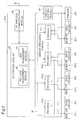
Fig. 2 is a functional block diagram schematically illustrating the
configuration of a sever PSV;
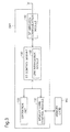
Fig. 3 is a functional block diagram schematically illustrating the
configuration of a digital camera CM1;
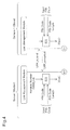
Fig. 4 shows the principle of connection authentication;
Fig. 5 shows the principle of connection authentication;
Fig. 6 shows the principle of connection authentication;
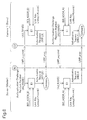
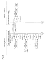
Fig. 7 shows a procedure of connection authentication executed in
an embodiment;
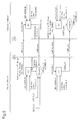
Fig. 8 shows the procedure of connection authentication executed
in the embodiment;
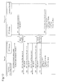
Fig. 9 shows the procedure of connection authentication executed
in the embodiment;
Fig. 10 is a functional block diagram schematically illustrating
the configuration of a server PSV';
Fig. 11 is a functional block diagram schematically illustrating the
configuration of a digital camera CM1';
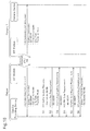
Fig. 12 shows potential problems arising in connection
authentication performed at establishment of communication links
according to the principle of the BT communication standard;
Fig. 13 shows a PIN code registration process in the procedure of
connection authentication of a second embodiment performed at
establishment of communication links;
Fig. 14 shows a process of connection authentication at
establishment of communication links performed after registration of PIN
codes in the case of prohibition of multiple connections via one registered
PIN code;
Fig. 15 shows a process of connection authentication at
establishment of communication links performed after registration of PIN
codes in the case of permission of multiple connections via one registered
PIN code;
Fig. 16 shows potential problems arising in connection
authentication performed after establishment of communication links
according to the principle of the BT communication standard;
Fig. 17 shows a PIN code registration process in the procedure of
connection authentication of a second embodiment performed after
establishment of communication links;
Fig. 18 shows a process of connection authentication after
establishment of communication links;
Fig. 19 shows the process of connection authentication after
establishment of communication links; and
Fig. 20 schematically illustrates the configuration of a print
service providing system as one modified example of the communication
network system of the invention.
Best Modes of Carrying Out the Invention
Some modes of carrying out the invention are discussed below as
preferred embodiments in the following sequence:
A. First Embodiment
A.1. Configuration of Print Service Providing System
Fig. 1 schematically illustrates a print service providing system as
one communication network system according to the technique of the
invention. The print service providing system includes a server PSV to
provide print services and a printer PR connected to the server PSV.
The server PSV has BT communication functions and works as a
BT access point (base station). According to the BT standard, seven BT
terminals (wireless communication terminals) at the maximum are
connectable to the server PSV. Seven monitors DP1 to DP7 are
accordingly linked to the server PSV to enable the maximum of seven
users to simultaneously receive the print services.
The server PSV provides the respective users with processes PS1
to PS7 of the print services through the displays on the monitors DP1 to
DP7. The processes PS1 to PS7 represent functional blocks to control
interfaces with the respective users and various services provided by the
server to the respective users, for example, the print services in this
embodiment. Each user utilizes the process of the print service provided
through the display on the monitor to receive the print service and print
images stored in the user's own BT terminal with the printer PR.
In the print service providing system of Fig. 1, seven digital
cameras CM1 to CM7 as the maximum number of BT terminals (slaves)
connectable with the server PSV are located in a communication range
(coverage) WA of the server PSV as the BT access point (master).
Fig. 2 is a functional block diagram schematically illustrating the
configuration of the sever PSV. The server PSV has a BT control module
20, a BT wireless communication module 30, a service providing module
40, and a printer control module 50. The server PSV naturally includes
internal storage devices and various control modules, as well as diversity
of peripheral devices, for example, external storage devices and wired
communication devices, and interfaces, for example, display interfaces
and input interfaces, generally included in the computer. These
components are, however, not directly related to the characteristics of the
invention and are thus neither illustrated nor explained here.
The BT control module 20 controls wireless communication made
by the BT wireless communication module 30. The BT control module 20
includes a link management module 22 that manages required connection
authentication for establishment of communication links with the
respective digital cameras CM1 to CM7 and a PIN code management
module (identification information management module) 24 that
allocates different PIN codes (different pieces of identification
information) to be individually registered in the respective digital
cameras CM1 to CM7. The respective processes PS1 to PS7 in the service
providing module 40 inform the individual users of the allocated PIN
codes through the display on the monitors DP1 to DP7. The operations of
the link management module 22 will be discussed later in detail.
The service providing module 40 carries out the 1st to the 7th
processes PS1 to PS7 to control the print services simultaneously
provided to seven users U1 to U7. The 1st to the 7th processes PS1 to PS7
display a guidance window for providing the print services on the
corresponding 1st to the 7th monitors DP1 to DP7. The print service
providing system also includes 1st to 7th input devices IP1 to IP7, for
example, touch panels or tablets, corresponding to the 1st to the 7th
monitors DP1 to DP7, although these input devices IP1 to IP7 are omitted
from the illustration of Fig. 1. In response to entry and selection by each
of the users U1 to U7 in the guidance window displayed on the
corresponding one of the monitors DP1 to DP7, the corresponding one of
the processes PS1 to PS7 makes the required print service.
The printer control module 50 controls the operations of the
printer PR in response to commands from each of the processes PS1 to
PS7 in the service providing module 40, so as to implement printing.
Fig. 3 is a functional block diagram schematically illustrating the
configuration of the digital camera CM1. The functional block diagram
of Fig. 3 shows only the configuration required for wireless
communication with the server PSV in the print service providing system
of Fig. 1. Imaging function-related components and other essential
components of the camera are omitted from the illustration of Fig. 3.
The digital camera CM1 includes an operation unit 120, a BT
control module 130, a BT wireless communication module 140, and a
memory card control module 150. A memory card MC is attachable to and
detachable from the digital camera CM1.
The operation unit 120 includes input means, such as switches and
a touch panel, for operations of the digital camera and display means.
The BT control module 130 controls wireless communication
made by the BT wireless communication module 140. The BT control
module 130 includes a link management module 132 that manages
required connection authentication for establishment of a communication
link with the server PSV. The operations of the link management module
132 will be discussed later in detail.
The memory card control module 150 controls writing and reading
of image data and other diverse data into and from the memory card MC.
The image data stored in the memory card MC may be transferred to the
server PSV via the BT control module 130.
The other digital cameras CM2 to CM7 have the same
configuration as that of the digital camera CM1 shown in Fig. 3 to
establish wireless communication with the server PSV in the print service
providing system of Fig. 1.
In the print service providing system of the above configuration,
when a user gives a start command of the print service in the window
displayed on the monitor, image data stored in the memory card of the
user's digital camera are transferred to a storage device (not shown) in the
server PSV and are displayed as a list of thumbnails or file names on the
monitor. When the user selects desired image data to be printed in the list
of image data and gives a print command, the selected image data are
transferred from the server PSV to the printer PR (see Fig. 1) to be printed.
Each user receives the independent print service according to the process
provided through the display on the monitor. Namely this print service
providing system enables each user to utilize the process provided
through the display on the monitor and receive the individual print
service.
A.2. Connection Authentication
In the print service providing system, establishment of the BT
wireless communication between the server PSV as the BT access point
(master) and each of the digital cameras CM1 to CM7 as the BT terminal
(slave) requires Piconet synchronization between the master and each
slave via a synchronization establishing phase according to the BT
communication standard and a subsequent shift to a communication
connection phase for packet communication.
The communication connection phase has two processing statuses,
that is, a connection status and a data transfer status. In the connection
status, control packets for establishing communication links and control
packets relating to securities are sent and received, while actual data
packets are not transmitted. In the data transfer status, on the other hand,
actual data packets are sent and received.
The BT communication standard uses radio waves for the
communication medium and accordingly does not have any physical
restriction between terminals, unlike cables. The radial propagation of
information transmitted by wireless requires securities to prevent
improper connection between the master and the slave and illegal
interception. The BT communication standard is accordingly designed to,
in response to a first shift to the connection status of the communication
connection phase via the synchronization establishing phase, prohibit a
further shift to the data transfer status for actual data transmission unless
completion of mutual connection authentication and encryption settings
between the master and the slave.
The description below sequentially regards the principle of
connection authentication defined in the BT communication standard,
potential problems arising in the conventional connection authentication,
and the procedure of connection authentication of this embodiment.
A.2.1. Principle of Connection Authentication
Figs. 4 through 6 show the principle of connection authentication
according to the BT communication standard, on the assumption that the
server PSV provides only one process PS1 and only one digital camera
CM1 possessed by one user U1 is connected to the server PSV in the print
service providing system of Fig. 1. In the description below, the server
PSV and the digital camera CM1 may respectively be referred to as the
master and as the slave.
The BT securities are managed by 128-bit secret keys called link
keys. Each link key represents a parameter for managing one-to-one
security between specified two terminals, and is not open to any third
terminal or entity. Communication by a communication protocol on an
upper layer than the level of a link management layer is not allowed
without this parameter setting between the master and the slave. Prior to
actual connection authentication, the link management module 22
included in the BT control module 20 of the master (server PSV) and the
link management module 132 included in the BT control module 130 of
the slave (digital camera CM1) cooperatively carry out a pairing process
to generate link keys between the master and the slave. Mutual
connection authentication is then performed by both the master and the
slave with the link keys. The detailed procedure of the standard pairing
and connection authentication processes is described below.
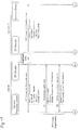
(1) Pairing Process
In the pairing process, the master and the slave first agree on
pairing as shown in Fig. 4. The master sends a control packet
'LMP_in_rand' to the slave to require generation of an initialization key
as a request for pairing with the slave. At this moment, the master
generates a 128-bit random number RAND_init as an initialization key
generation random number used for generation of the initialization key
and sends the initialization key generation random number RAND_init to
the slave.
The slave sends back a control packet 'LMP_accepted' to accept
the request for pairing. This reaches an agreement on pairing between the
master and the slave. The slave otherwise sends back a control packet
'LMP_not_accepted' to reject the request for pairing.
The master and the slave individually generate the initialization
keys, in response to the agreement on pairing.
The initialization key is computed from three input parameters, a
PIN code, a PIN code length, and the initialization key generation random
number RAND_init, according to an initialization key algorithm (E22).
The initialization key generation random number RAND_init has been
sent from the master to the slave at the time of agreement on pairing.
Input of an identical PIN code in both the link management module 22 of
the master (server PSV) and the link management module 132 of the slave
(digital camera CM1) leads to generation of an identical initialization key
Kinit.
When the user U1 operates the input device IP1 to enter a PIN code,
the process PS1 causes the PIN code and the PIN code length to be input
into the link management module 22 of the master. Similarly when the
user U1 operates the input unit of the operation unit 120 to enter a PIN
code, the PIN code and the PIN code length are input into the link
management module 132 of the slave. The PIN code entered by the user
is a variable-length value of maximum 16 bytes (128 bits). When the PIN
code length of the input PIN code is less than 16 bytes, adequate digits are
supplemented.
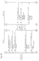
The master and the slave then make a negotiation on setting of a
composite key to a link key as shown in Fig. 5. The master sends a control
packet 'LMP_comb_key' to the slave to request registration of a
composite key as a link key. At this moment, the master generates a
128-bit random number LK_RAND_A as a 1st composite key generation
random number used for generation of a composite key and sends the
composite key generation random number LK_RAND_A to the slave.
Similarly the slave sends a control packet 'LMP_comb_key' to the
master. At this moment, the slave generates a 128-bit random number
LK_RAND_B as a 2nd composite key generation random number and
sends the composite key generation random number LK_RAND_B to the
master.
These composite key generation random numbers LK_RAND_A
and LK_RAND_B are to be not open to any third terminal or entity. The
master accordingly sends an exclusive OR of the initialization key Kinit
and the 1st composite key generation random number LK_RAND_A to the
slave, whereas the slave sends an exclusive OR of the initialization key
Kinit and the 2nd composite key generation random number LK_RAND_B
to the master. The master and the slave mutually exchange the 1st
composite key generation random number LK_RAND_A and the 2nd
composite key generation random number LK_RAND_B by computing an
exclusive OR of the initialization key Kinit and the received exclusive
OR.
In response to the successful negotiation between the master and
the slave on setting of the composite key to the link key, the master and
the slave individually generate composite keys.
The composite key is generated as an exclusive OR of a temporary
single key of the master and a temporary single key of the slave. The
temporary single key of the master is computed from two input
parameters, a BT address BD_ADDR_A of the master and the 1st
composite key generation random number LK_RAND_A, according to a
single key algorithm (E21). The temporary single key of the slave is
computed from two input parameters, a BT address BD_ADDR_B of the
slave and the 2nd composite key generation random number LK_RAND_B,
according to the single key algorithm (E21).
The two composite key generation random numbers LK_RAND_A
and LK_RAND_B are exchanged between the master and the slave at the
negotiation. The respective BT addresses BD_ADDR_A and
BD_ADDR_B are exchanged between the master and the slave in the
synchronization establishing phase and are known parameters to both the
master and the slave. The master and the slave are thus expected to
individually generate identical temporary single keys LK_KA of the
master and identical temporary single keys LK_KB of the slave and
thereby to individually generate identical composite keys Kcomb as an
exclusive OR of these two identical temporary single keys LK_KA and
LK_KB. The individually generated composite keys Kcomb are set to
link keys Linkey and are registered respectively in non-illustrated
memories of the master and the slave.
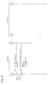
(2) Connection Authentication Process
Connection authentication is then performed with the link keys
Linkey individually generated and set by the master and the slave as
shown in Fig. 6. The slave first gives an authentication request to the
master and the master then gives an authentication request to the slave for
mutual connection authentication.
The master sends a control packet 'LMP_au_rand' to the slave. At
this moment, the master generates a 128-bit authentication challenge
random number AU_RAND and sends the authentication challenge
random number AU_RAND to the slave. The master also computes an
authentication response parameter SRES_B' from three input parameters,
the link key Linkey (= Kcomb), the BT address BD_ADDR_B of the slave,
and the authentication challenge random number AU_RAND, according
to a connection authentication algorithm (E1).
The slave receives the authentication challenge random number
AU_RAND in the control packet 'LMP_au_rand' and similarly computes
an authentication response parameter SRES_B from three input
parameters, the link key Linkey (= Kcomb), the BT address BD_ADDR_B
of the slave, and the authentication challenge random number AU_RAND,
according to the connection authentication algorithm (E1). The slave
subsequently sends a control packet 'LMP_sres' to the master to request
the master to perform connection authentication. At this moment, the
slave sends the computed authentication response parameter SRES_B in
the control packet 'LMP_sres' to the master.
The master receives the authentication response parameter
SRES_B and compares the received authentication response parameter
SRES_B with the computed authentication response parameter SRES_B'
to give permission for or place a prohibition on connection with the slave.
This completes authentication of the slave performed by the master.
An authentication request by the master is given in the opposite
direction to the authentication request by the slave. The slave first sends
a control packet 'LMP_au_rand' to the master. At this moment, the slave
generates a 128-bit authentication challenge random number AU_RAND
and sends the authentication challenge random number AU_RAND to the
master. The slave also computes an authentication response parameter
SRES_A' from three input parameters, the link key Linkey (= Kcomb), the
BT address BD_ADDR_A of the master, and the authentication challenge
random number AU_RAND, according to the connection authentication
algorithm (E1).
The master receives the authentication challenge random number
AU_RAND in the control packet 'LMP_au_rand' and similarly computes
an authentication response parameter SRES_A from three input
parameters, the link key Linkey (= Kcomb), the BT address BD_ADDR_A
of the master, and the authentication challenge random number
AU_RAND, according to the connection authentication algorithm (E1).
The master subsequently sends a control packet 'LMP_sres' to the slave to
request the slave to perform connection authentication. At this moment,
the master sends the computed authentication response parameter
SRES_A in the control packet 'LMP_sres' to the slave.
The slave receives the authentication response parameter SRES_A
and compares the received authentication response parameter SRES_A
with the computed authentication response parameter SRES_A' to give
permission for or place a prohibition on connection with the master. This
completes authentication of the master performed by the slave.
The successful authentication by both the master and the slave
completes the connection authentication. Generation of different link
keys by the master and the slave, that is, a difference in any of the
common parameters used for generation of the link keys, leads to
inconsistency of the computed authentication response parameters and
resulting failure in establishment of connection. This technique ensures
security between the master and the slave.
A.2.2. Problems
The principle discussed above is successfully applied to
connection authentication in the case of connection of only one slave (BT
terminal) to one master (BT access point). The connection authentication
according to the above principle, however, has some problems in the case
of simultaneous connection of the multiple digital cameras CM1 to CM7
as the slaves to the server PSV as the master to constitute one Piconet as
in the print service providing system of the embodiment shown in Fig. 1.
One available technique sets a common PIN code to be used in the
Piconet and gives the common PIN code to the respective users U1 to U7
through the display on the monitors DP1 to DP7. The given common PIN
code is input into the own digital cameras CM1 to CM7 by the respective
users U1 to U7.
Individual connection authentications between the respective
digital cameras CM1 to CM7 and the server PSV according to the above
principle enable establishment of the respective communication links. In
this case, only the inherent BT addresses are usable as the identification
parameter for discriminating the seven digital cameras CM1 to CM7. For
one-to-one mapping of the seven digital cameras CM1 to CM7 to the
seven processes PS1 to PS7 used by the seven users U1 to U7 with a
common PIN code, the respective users U1 to U7 are required to notify the
corresponding processes PS1 to PS7 of the inherent BT addresses of the
own digital cameras CM1 to CM7. As described above as the drawbacks
of the prior art technique, it is rather undesirable to ask such notification
to the general users.
Another available technique allocates different PIN codes PIN_1
to PIN_7 to the processes PS1 to PS7 used by the respective users U1 to
U7 and gives the allocated PIN codes PIN_1 to PIN_7 to the respective
users U1 to U7 through the display on the monitors DP1 to DP7. The
given PIN codes PIN_1 to PIN_7 are input into the own digital cameras
CM1 to CM7 by the respective users U1 to U7.
The master is notified of the PIN codes PIN_1 to PIN_7 allocated
to the respective processes PS1 to PS7. The PIN code is, however, not
directly used for actual transmission of data packets between the master
and the slaves in the synchronization establishing phase or the
communication connection phase as described previously. The master or
the server PSV is accordingly not informed of which of the seven
different PIN codes is input in which of the seven slaves or the seven
digital cameras CM1 to CM7. This leads to failed specification of an
adequate link key, which is generated corresponding to one of the seven
PIN codes, to be used for each of the seven digital cameras CM1 to CM7
in the process of connection authentication between the respective digital
cameras CM1 to CM7 and the server PSV.
Connection authentication is, however, possible even in this case.
The technique sequentially selects one of the seven PIN codes PIN_1 to
PIN_7 for each of the seven digital cameras CM1 to CM7 and performs the
connection authentication according to the principle discussed above.
The 1st digital camera requires up to 7 cycles of the connection
authentication. The 2nd, 3rd, 4th, 5th, 6th, and 7th digital cameras
respectively require up to 6 cycles, 5 cycles, 4 cycles, 3 cycles, 2 cycles,
and 1 cycle of the connection authentication. Namely the maximum of 28
cycles of the connection authentication enable the seven digital cameras
CM1 to CM7 to be one-to-one mapped to the seven processes PS1 to PS7
used by the seven users U1 to U7.
This technique is, however, remarkably inefficient to require up to
28 cycles of the connection authentication for completed connection
authentication with regard to all the seven digital cameras CM1 to CM7.
The embodiment accordingly adopts the following technique for
connection authentication.
A.2.3. Connection Authentication of Embodiment
Figs. 7 through 9 show a procedure of connection authentication
executed in this embodiment. The procedure of connection
authentication shown in Figs. 7 through 9 is on the assumption that the
server PSV provides the 1st to the 7th processes PS1 to PS7 as shown in Fig.
1. The following description specifically regards connection
authentication between the 1st digital camera CM1 and the server PSV
among connection authentications between the server PSV and the
respective digital cameras CM1 to CM7 possessed by the seven users U1
to U7. In the description below, the server PSV and the 1st digital camera
CM1 may respectively be referred to as the master and as the slave.
The connection authentication procedure of this embodiment
basically follows the sequence of the principle discussed above. The link
management module 22 included in the BT control module 20 of the
master (server PSV) and the link management module 132 included in the
BT control module 130 of the slave (1st digital camera CM1)
cooperatively carry out a pairing process to generate link keys between
the master and the slave. Mutual connection authentication is then
performed by both the master and the slave with the link keys. The
detailed procedure of the pairing and connection authentication processes
of the embodiment is described below.
(1) Pairing Process
In the pairing process, the master and the slave first agree on
pairing as shown in Fig. 7. The master sends a control packet
'LMP_in_rand' to the slave to require generation of an initialization key
as a request for pairing with the slave. The master generates an
initialization key generation random number RAND_init and sends the
initialization key generation random number RAND_init to the slave.
The slave sends back a control packet 'LMP_accepted' to accept
the request for pairing. This reaches an agreement on pairing between the
master and the slave. The master and the slave then individually generate
the initialization keys, in response to the agreement on pairing.
In the master, PIN codes allocated to the respective processes PS1
to PS7 by the PIN code management module 24 (see Fig. 2) and respective
PIN code lengths are input into the link management module 22.
Initialization keys Kinit_1 to Kinit_7 respectively corresponding to the
input PIN codes are computed according to the initialization key
algorithm (E22) as shown by Expressions (a1) to (a7) given below. In this
example, the PIN codes allocated to the respective processes PS1 to PS7
are PIN_1 to PIN_7 and have PIN code lengths PIN_1_Lng to PIN_7_Lng:
Kinit_1 = E22(RAND_init, PIN_1, PIN_1_Lng)
Kinit_2 = E22(RAND_init, PIN_2, PIN_2_Lng)
Kinit_3 = E22(RAND_init, PIN_3, PIN_3_Lng)
Kinit_4 = E22(RAND_init, PIN_4, PIN_4_Lng)
Kinit_5 = E22(RAND_init, PIN_5, PIN_5_Lng)
Kinit_6 = E22(RAND_init, PIN_6, PIN_6_Lng)
Kinit_7 = E22(RAND_init, PIN_7, PIN_7_Lng)
The user U1 of the 1st digital camera CM1 operates the operation
unit 120 (see Fig. 1) to enter the PIN code PIN_1 allocated to the 1st
process PS1 into the slave. The link management module 132 then
receives the PIN code PIN_1 and its PIN code length PIN_1_Lng. An
initialization key Kinit_trm is computed according to the initialization
key algorithm (E22) as shown by Expression (b1) given below:
Kinit_trm = E22(RAND_init, PIN_1, PIN_1_Lng)
The master and the slave then make a negotiation on setting of a
composite key to a link key as shown in Fig. 8. The master sends a control
packet 'LMP_comb_key' to the slave to request registration of a
composite key as a link key.
In the principle of connection authentication discussed above, the
master generates the 1st composite key generation random number
LK_RAND_A, computes an exclusive OR of the initialization key Kinit
and the 1st composite key generation random number LK_RAND_A, and
sends the result of the exclusive OR in the control packet
'LMP_comb_key' to the slave, as shown in Fig. 5. The embodiment,
however, can not adopt the same procedure, since the master has
computed seven possible options of the initialization key Kinit_1 to
Kinit_7.
In the system of the embodiment, the master generates a 128-bit
random number COMB_RAND_A and sends the COMB_RAND_A to the
slave. Exclusive ORs (XORs) of the random number COMB_RAND_A
and the respective possible options of the initialization key Kinit_1 to
Kinit_7 give seven possible options of 1st composite key generation
random number LK_RAND_A_1 to LK_RAND_A_7 as shown by
Expressions (c1) to (c7) given below:
LK_RAND_A_1 = (COMB_RAND_A)XOR(Kinit_1)
LK_RAND_A_2 = (COMB_RAND_A)XOR(Kinit_2)
LK_RAND_A_3 = (COMB_RAND_A)XOR(Kinit_3)
LK_RAND_A_4 = (COMB_RAND_A)XOR(Kinit_4)
LK_RAND_A_5 = (COMB_RAND_A)XOR(Kinit_5)
LK_RAND_A_6 = (COMB_RAND_A)XOR(Kinit_6)
LK_RAND_A_7 = (COMB_RAND_A)XOR(Kinit_7)
Similarly the slave computes an exclusive OR (XOR) of the
random number COMB_RAND_A sent from the master and the
initialization key Knit_trm to give a 1st composite key generation random
number LK_RAND_A_trm as shown by Expression (d1) given below:
LK_RAND_A_trm = (COMB_RAND_A)XOR(Kinit_trm)
In the same manner as the principle of connection authentication
shown in Fig. 5, the slave generates a 2nd composite key generation
random number LK_RAND_B, computes an exclusive OR of the 2nd
composite key generation random number LK_RAND_B and the
initialization key Kinit_trm, and sends the result of the exclusive OR as
a random number COMB_RAND_B in the control packet
'LMP_comb_key' to the master.
The master receives the random number COMB_RAND_B and
computes exclusive ORs (XORs) of the received random number
COMB_RAND_B and the possible options of the initialization key
Kinit_1 to Kinit_7 to give seven possible options of 2nd composite key
generation random number LK_RAND_B_1 to LK_RAND_B_7 as shown
by Expressions (e1) to (e7) given below:
LK_RAND_B_1 = (COMB_RAND_B)XOR(Kinit_1)
LK_RAND_B_2 = (COMB_RAND_B)XOR(Kinit_2)
LK_RAND_B_3 = (COMB_RAND_B)XOR(Kinit_3)
LK_RAND_B_4 = (COMB_RAND_B)XOR(Kinit_4)
LK_RAND_B_5 = (COMB_RAND_B)XOR(Kinit_5)
LK_RAND_B_6 = (COMB_RAND_B)XOR(Kinit_6)
LK_RAND_B_7 = (COMB_RAND_B)XOR(Kinit_7)
In response to the successful negotiation between the master and
the slave on setting of the composite key to the link key, the master and
the slave individually generate composite keys.
The master executes the single key algorithm (E21) to compute
possible options of temporary single key of the master LK_KA_1 to
LK_KA_7 and possible options of temporary single key of the slave
LK_KB_1 to LK_KB_7 as shown by Expressions (f1) to (f7) and (g1) to
(g7) given below:
LK_KA_1 =E21(LK_RAND_A_1, BD_ADDR_A)
LK_KA_2 =E21(LK_RAND_A_2, BD_ADDR_A)
LK_KA_3 =E21(LK_RAND_A_3, BD_ADDR_A)
LK_KA_4 =E21(LK_RAND_A_4, BD_ADDR_A)
LK_KA_5 =E21(LK_RAND_A_5, BD_ADDR_A)
LK_KA_6 =E21(LK_RAND_A_6, BD_ADDR_A)
LK_KA_7 =E21(LK_RAND_A_7, BD_ADDR_A)
LK_KB_1 =E21(LK_RAND_B_1, BD_ADDR_B)
LK_KB_2 =E21(LK_RAND_B_2, BD_ADDR_B)
LK_KB_3 =E21(LK_RAND_B_3, BD_ADDR_B)
LK_KB_4 =E21(LK_RAND_B_4, BD_ADDR_B)
LK_KB_5 =E21(LK_RAND_B_5, BD_ADDR_B)
LK_KB_6 =E21(LK_RAND_B_6, BD_ADDR_B)
LK_KB_7 =E21(LK_RAND_B_7, BD_ADDR_B)
Exclusive ORs (XORs) of the possible options of the temporary
single key of the master LK_KA_1 to LK_KA_7 and the possible options
of the temporary single key of the slave LK_KB_1 to LK_KB_7 give
possible options of composite key Kcomb_1 to Kcomb_7 as shown by
Expressions (h1) to (h7) given below:
Kcomb_1 = (LK_KA_1)XOR(LK_KB_1)
Kcomb_2 = (LK_KA_2)XOR(LK_KB_2)
Kcomb_3 = (LK_KA_3)XOR(LK_KB_3)
Kcomb_4 = (LK_KA_4)XOR(LK_KB_4)
Kcomb_5 = (LK_KA_5)XOR(LK_KB_5)
Kcomb_6 = (LK_KA_6)XOR(LK_KB_6)
Kcomb_7 = (LK_KA_7)XOR(LK_KB_7)
Similarly the slave executes the single key algorithm (E21) to
compute a temporary single key of the master LK_KA_trm and a
temporary single key of the slave LK_KB_trm as shown by Expressions
(i1) and (j1) given below:
LK_KA_trm =E21(LK_RAND_A_trm, BD_ADDR_A)
LK_KB_trm =E21 (LK_RAND_B_trm, BD_ADDR_B)
An exclusive OR (XOR) of the temporary single key of the master
LK_KA_trm and the temporary single key of the slave LK_KB_trm gives
a composite key Kcomb_trm as shown by Expression (k1) given below:
Kcomb_trm = (LK_KA_trm)XOR(LK_KB_trm)
The possible options of the composite key Kcomb_1 to Kcomb_7
generated by the master are set to possible options of the link key Linkey
and are registered in the non-illustrated memory of the master. The
composite key Kcomb_trm generated by the slave is set to the link key
Linkey and is registered in the non-illustrated memory of the slave.
(2) Connection Authentication Process
Connection authentication is then performed with the link keys
individually generated and set by the master and the slave as shown in Fig.
9. The slave first gives an authentication request to the master and the
master then gives an authentication request to the slave for mutual
connection authentication.
In the same manner as the principle of connection authentication
shown in Fig. 6, the master generates an authentication challenge random
number AU_RAND and sends the authentication challenge random
number AU_RAND on a control packet 'LMP_au_rand' to the slave. The
master also executes the connection authentication algorithm (E1) to
compute an authentication response parameter. Unlike the procedure of
the principle, however, the master computes seven possible options of the
authentication response parameter SRES_1 to SRES_7 corresponding to
the seven possible options of the composite key Kcomb_1 to Kcomb_7,
which are set to the possible options of the link key Linkey, as shown by
Expressions (m1) to (m7) given below:
SRES_1 =E1(Kcomb_1, BD_ADDR_B, AU_RAND)
SRES_2 =E1(Kcomb_2, BD_ADDR_B, AU_RAND)
SRES_3 =E1(Kcomb_3, BD_ADDR_B, AU_RAND)
SRES_4 =E1(Kcomb_4, BD_ADDR_B, AU_RAND)
SRES_5 =E1(Kcomb_5, BD_ADDR_B, AU_RAND)
SRES_6 =E1(Kcomb_6, BD_ADDR_B, AU_RAND)
SRES_7 =E1(Kcomb_7, BD_ADDR_B, AU_RAND)
The slave receives the authentication challenge random number
AU_RAND and computes an authentication response parameter
SRES_trm as shown by Expression (n1) given below in the same manner
as the principle of connection authentication discussed above:
SRES_trm =E1(Kcomb_trm, BD_ADDR_B, AU_RAND)
The slave sends the computed authentication response parameter
SRES_trm on a control packet 'LMP_sres' to the master to request the
master to perform connection authentication.
The master receives the authentication response parameter
SRES_trm and successively compares the received authentication
response parameter SRES_trm with the computed possible options of the
authentication response parameter SRES_1 to SRES_7 to find the
matching option of the authentication response parameter. In this
example, only the 1st option of the authentication response parameter
SRES_1 matches with the received authentication response parameter
SRES_trm. This completes connection authentication of the 1st digital
camera CM1 as the slave by the server PSV as the master in response to
the connection authentication request from the slave. This connection
authentication gives one-to-one mapping of the 1st digital camera CM1 to
the 1st process PS1, which is related to the 1st PIN code PIN_1 used for
computation of the 1st option of the authentication response parameter
SRES_1.
On completion of the connection authentication in response to the
connection authentication request from the 1st digital camera CM1 as the
slave to the server PSV as the master, connection authentication is
performed in response to a connection authentication request from the
server PSV as the master to the 1st digital camera CM1 as the slave. In the
same manner as the principle of connection authentication shown in Fig.
6, the slave generates an authentication challenge random number
AU_RAND and sends the authentication challenge random number
AU_RAND in the control packet 'LMP_au_rand' to the master. The slave
also executes the connection authentication algorithm (E1) to compute
the authentication response parameter SRES_trm as shown by Expression
(n1) given above.
The master receives the authentication challenge random number
AU_RAND and executes the connection authentication algorithm (E1)
with the link key Linkey (= Kcomb_1 in this example), which is specified
by the connection authentication request from the slave, to compute the
authentication response parameter SRES_1 as shown by Expression (m1)
given above. The master sends the computed authentication response
parameter SRES_1 in the control packet 'LMP_sres' to the slave to request
the slave to perform connection authentication.
The slave receives the authentication response parameter SRES_1
and compares the received authentication response parameter SRES_1
with the computed authentication response parameter SRES_trm for
matching. This completes authentication of the master performed by the
slave.
The successful authentication by both the master and the slave
completes the connection authentication.
The other digital cameras CM2 to CM7 also perform the
connection authentication according to the above procedure. The master
is not required to use all the seven possible options of the authentication
response parameter, which are generated corresponding to the seven
possible options of the composite key, for connection authentication of
each of the seven digital cameras CM1 to CM7. The matching options of
the authentication response parameter in the previous connection
authentication may be excluded from the options for matching in the
subsequent connection authentication.
A.3. Effects
In the procedure of this embodiment described above, in response
to the connection authentication requests from the 1st to the 7th digital
cameras CM1 to CM7 as the slaves, the sever PSV as the master performs
connection authentication of the 1st to the 7th digital cameras CM1 to CM7,
while identifying the PIN codes input respectively into the 1st to the 7th
digital cameras CM1 to CM7. The PIN code management module 24
manages the PIN codes PIN_1 to PIN_7 allocated to the 1st to the 7th
processes PS1 to PS7. The 1st to the 7th processes PS1 to PS7 utilized by
the users U1 to U7 of the respective digital cameras CM1 to CM7 are thus
one-to-one mapped to the 1st to the 7th digital cameras CM1 to CM7.
The connection authentication of this embodiment requires the
user to enter only one simple PIN code into the own digital camera. The
user is then allowed to make the BT wireless communication with only
one specified process.
In the connection authentication of this embodiment, the sequence
of transmission of the control packets between the server PSV as the
master and the digital camera as the slave is consistent with the sequence
described in the principle of connection authentication. The digital
camera as the slave is thus not required to have any special mechanism for
the connection authentication of this embodiment but advantageously
utilizes the general BT communication functions to receive the print
service provided by the print service providing system of the
embodiment.
The above example regards the connection authentication between
the server as the master and the digital camera as the slave. This
relationship is, however, not essential, and the connection authentication
may be performed according to the same procedure between the digital
camera as the master and the server as the slave.
B. Second Embodiment
B.1. Configuration of Print Service Providing System
A server PSV' as a BT access point (base station) and digital
cameras CM1' to CM7' as BT terminals (wireless communication
terminals) are constructed as discussed below in a print service providing
system of a second embodiment.
Fig. 10 is a functional block diagram schematically illustrating
the configuration of the server PSV'. The server PSV' includes a
computer 200 as a service providing device that provides print services
and a BT module 300 that is connected to the computer 200 and makes BT
wireless communication.
The service providing device 200 and the BT module 300 may be
interconnected by a physical IF (interface), such as a UART (Universal
Asynchronous Receiver Transmitter) or a USB (Universal Serial Bus),
and are connected by the USB in this embodiment.
The service providing device 200 naturally includes internal
storage devices and various control modules, as well as diversity of
peripheral devices, for example, external storage devices and wired
communication devices, and interfaces, for example, display interfaces
and input interfaces, generally included in the computer. These
components are, however, not directly related to the characteristics of the
invention and are thus neither illustrated nor explained here.
The service providing device 200 includes a service providing unit
210, a printer control unit 220, and a BT control unit 230. Like the
service providing module 40 of the first embodiment shown in Fig. 2, the
service providing unit 210 carries out 1st to the 7th processes PS1 to PS7
to control the print services simultaneously provided to seven users U1 to
U7. The 1st to the 7th processes PS1 to PS7 display a guidance window for
providing the print services on corresponding 1st to 7th monitors DP1 to
DP7 (not shown). There are 1st to 7th input devices IP1 to IP7 (not shown),
for example, touch panels or tablets, corresponding to the 1st to the 7th
monitors DP1 to DP7. In response to entry and selection by each of the
users U1 to U7 in the guidance window displayed on the corresponding
one of the monitors DP1 to DP7, the corresponding one of the processes
PS1 to PS7 makes the required print service. Like the printer control
module 50 of the first embodiment shown in Fig. 2, the printer control
unit 220 controls the operations of a printer PR (not shown) in response
to commands from each of the processes PS1 to PS7 in the service
providing unit 210, so as to implement printing. The BT control unit 30
controls wireless communication made by the BT module 300.
The BT module 300 includes a BT control unit 310 and a BT
wireless communication unit 320. The BT wireless communication unit
320 has the functions of actually receiving and sending data by wireless
and is typically a transceiver. The BT control unit 310 controls wireless
communication made by the BT wireless communication unit 320
according to the control by the BT control unit 230 of the service
providing device 200.
In the description below, the BT control unit 230 of the service
providing device 200 and the BT control unit 310 of the BT module 300
may respectively be called the 'service-side BT control unit 230' and the
'module-side BT control unit 310'.
The service-side BT control unit 230 has an HCI controller 234,
whereas the module-side BT control unit 310 has an HCI controller 316.
These HCI controllers 234 and 316 are logic IFs mounted on the physical
IFs for connecting the service providing device 200 with the BT module
300, and control communication between the service-side BT control unit
230 and the module-side BT control unit 310 according to an HCI (Host
Control Interface) defined in the BT communication standard. In the
description below, the HCI controller 234 of the service-side BT control
unit 230 and the HCI controller 316 of the module-side BT control unit
310 may respectively be called the 'service-side HCI controller 234' and
the 'module-side HCI controller 316'.
The service-side BT control unit 230 further includes a PIN code
allocation management unit 232, whereas the module-side BT control unit
310 further includes a PIN code management unit 314. The PIN code
allocation management unit 232 generates multiple different PIN codes
(multiple different pieces of identification information) to be allocated to
the respective processes PS1 to PS7. The PIN code allocation
management unit 232 notifies the PIN code management unit 314 of the
allocated PIN codes via the respective HCI controllers 234 and 316. The
service-side BT control unit 230 receives information representing a
mapping of connection handles for identifying the respective BT
terminals as the other side of communication to the PIN codes used for
connection authentication of communication from the module-side BT
control unit 310 and manages the received information.
The PIN code management unit 314 holds and manages the PIN
codes notified by the PIN code allocation management unit 232 via the
service-side HCI controller 234 and the module-side HCI controller 316.
The module-side BT control unit 310 also includes a link
management unit 312. The link management unit 312 manages required
connection authentication for establishment of a communication link
between each of the BT terminals (the digital cameras CM1' to CM7' in
this embodiment) and the server PSV' as the BT access point. The
functions of the link management unit 312 are identical with the link
management module 22 of the first embodiment shown in Fig. 2.
As clearly understood from the above explanation, the
combination of the service-side BT control unit 230 and the module-side
BT control unit 310 is equivalent to the BT control module 20 (see Fig. 2)
in the server PSV of the first embodiment.
Fig. 11 is a functional block diagram schematically illustrating the
configuration of the digital camera CM1'. The digital camera CM1'
includes a computer 400 as a camera device having imaging functions and
a BT module 500 that is connected to the computer 400 and makes BT
wireless communication.
The camera device 400 and the BT module 500 may be
interconnected via a physical IF, such as a UART or a USB, and are
connected by the USB in this embodiment.
The illustration of Fig. 11 shows only part of the structure of the
camera device 400 related to the BT wireless communication with the
server PSV', and essential components of the imaging device, for example,
the imaging functions, are omitted from the illustration.
The camera device 400 includes an operation unit 410, a BT
control unit 420, and a memory card control unit 430. Like the operation
unit 120 of the first embodiment shown in Fig. 3, the operation unit 410
includes input means, such as switches and a touch panel, for operations
of the digital camera and display means. The memory card control unit
430 controls writing and reading of image data and other diverse data into
and from a non-illustrated memory card MC, like the memory card control
module 150 of the first embodiment shown in Fig. 3. The BT control unit
420 controls wireless communication made by the BT module 500.
The BT module 500 includes a BT control unit 510 and a BT
wireless communication unit 520. The BT wireless communication unit
520 has the functions of actually receiving and sending data by wireless
and is typically a transceiver. The BT control unit 510 controls wireless
communication made by the BT wireless communication unit 520
according to the control by the BT control unit 420 of the camera device
400.
In the description below, the BT control unit 420 of the camera
device 400 and the BT control unit 510 of the BT module 500 may
respectively be called the 'camera-side BT control unit 420' and the
'module-side BT control unit 510'.
The camera-side BT control unit 420 has an HCI controller 424,
whereas the module-side BT control unit 510 has an HCI controller 516.
These HCI controllers 424 and 516 are logic IFs mounted on the physical
IFs for connecting the camera device 400 with the BT module 500, and
control communication between the camera-side BT control unit 420 and
the module-side BT control unit 510 according to the HCI (Host Control
Interface) defined in the BT communication standard. In the description
below, the HCI controller 424 of the camera-side BT control unit 420 and
the HCI controller 516 of the module-side BT control unit 510 may
respectively be called the 'camera-side HCI controller 424' and the
'module-side HCI controller 516'.
The module-side BT control unit 510 further includes a link
management unit 512. The link management unit 512 manages required
connection authentication for establishment of a communication link
with the server PSV' as the BT access point. The functions of the link
management unit 512 are identical with the link management module 132
of the first embodiment shown in Fig. 3.
Image data stored in the non-illustrated memory card MC are
transferred to the server PSV' via the camera-side BT control unit 420 and
the module-side BT control unit 510.
As clearly understood from the above explanation, the
combination of the camera-side BT control unit 420 and the module-side
BT control unit 510 is equivalent to the BT control module 130 (see Fig.
3) in the digital camera CM1 of the first embodiment.
In the print service providing system of the second embodiment,
the other digital cameras CM2' to CM7' have the same structure related to
the wireless communication with the server PSV' as that of the digital
camera CM1' shown in Fig. 11.
Like the print service providing system of the first embodiment
(Fig. 1), the print service providing system of the second embodiment
including the server PSV' connecting with the 1st to the 7th digital
cameras CM1' to CM7' enables each user to utilize the process provided
through the display on the monitor and receive the individual print
service.
The connection authentication executed in the print service
providing system of the second embodiment is described below in two
different situations, that is, connection authentication at establishment of
communication links and connection authentication after establishment
of communication links.
B.2. Connection Authentication at Establishment of Links
The description sequentially regards potential problems arising in
connection authentication at establishment of communication links (ACL
(Asynchronous Connection-Less) links) according to the principle of the
BT communication standard and the procedure of connection
authentication of this embodiment.
B.2.1. Problems
Fig. 12 shows potential problems arising in connection
authentication performed at establishment of communication links
according to the principle of the BT communication standard. Fig. 12
shows the situation of connection authentication on the assumption that
the PIN code allocation management unit 232 and the PIN code
management unit 314 characteristic of the embodiment are omitted
respectively from the service-side BT control unit 230 and from the
module-side BT control unit 310 in the server PSV' shown in Fig. 10. In
the situation of Fig. 12, the service providing unit 210 provides the 1st to
the 7th processes PS1 to PS7 to connect the digital cameras CM1' to CM7'
possessed by the seven users U1 to U7 with this modified server PSV'.
Fig. 12 specifically shows connection authentication between the 1st
digital camera CM1' and the modified server PSV' in mutual connection
authentications between the respective digital cameras CM1' to CM7' and
the modified server PSV'. The 1st to the 7th processes PS1 to PS7 of the
service providing unit 210 provide the 1st to the 7th users U1 to U7 with
PIN codes to be input into the 1st to the 7th digital cameras CM1' to CM7'
through the displays on the respective monitors (not shown). In the
description below, this modified server PSV' may simply be called the
server, and the 1st to the 7th digital cameras CM1' to CM7' may simply be
called the cameras 1 to 7. The digital cameras may otherwise be called
the BT terminals.
For establishment of a communication link, at a first step (S1) in
the server (see Fig. 10), the service-side HCI controller 234 of the service
providing device 200 enables a command parameter
'Authentication_Enable' and sends a control command
'HCI_Write_Authentication_Enable' to the module-side HCI controller
316 of the BT module 300. The command parameter
'Authentication_Enable' is enabled or disabled for connection
authentication at establishment of communication links. The output of
the control command 'HCI_Write_Authentication_Enable' triggers
authentication in the course of establishment of a communication link
between the server and the BT terminal (camera 1). The service providing
device 200 and the BT module 300 in the server make communication via
the service-side HCI controller 234 and the module-side HCI controller
316, as described previously. In the description below, the expression of
'from the service-side HCI controller 234 of the service providing device
200 to the module-side HCI controller 316 of the BT module 300' may be
abbreviated as 'from the service providing device 200 to the BT module
300' or as 'from the service-side BT control unit 230 to the module-side
BT control unit 310'.
At a second step (S2) in the camera 1 (see Fig. 11), the camera-side
HCI controller 424 of the camera device 400 sends a control command
'HCI_Create_Connection' with the BT address of the server as a command
parameter (parameter name 'BD_ADDR') to the module-side HCI
controller 516 of the BT module 500. This triggers a paging process to
send a page from the camera 1 to the server. The server correspondingly
sends back a page response to the camera 1. The camera device 400 and
the BT module 500 in the camera 1 make communication via the
camera-side HCI controller 424 and the module-side HCI controller 516,
as described previously. In the description below, the expression of 'from
the camera-side HCI controller 424 of the camera device 400 to the
module-side HCI controller 516 of the BT module 500' may be
abbreviated as 'from the camera device 400 to the BT module 500' or as
the 'camera-size BT control unit 420 to the module-side BT control unit
510'.
The page and the page response transmitted between the server
and the camera 1 start connection authentication between the link
management unit 312 in the module-side BT control unit 310 of the server
and the link management unit 512 in the module-side BT control unit 510
of the camera 1, since the authentication setting has been enabled at the
first step (S1).
In the first execution of connection authentication, the link
management unit 312 in the module-side BT control unit 310 of the server
does not have a link key required for authentication described in the first
embodiment. At a third step (S3) in the server, the BT module 300 sends
an event 'HCI_Link_key_Request_event' with the BT address of the BT
terminal to be authenticated (camera 1 in this example) as the command
parameter (parameter name 'BD_ADDR') to the service providing device
200 as a request for the link key.
As mentioned previously in the first embodiment as the problems
of the conventional connection authentication, the service-side BT
control unit 230 is not informed of the BT address of the BT terminal
(camera 1) and accordingly can not send back a corresponding link key.
At a fourth step (S4) in the server, the service providing device 200 sends
a control command 'HCI_Link_Key_Negative_Request_reply' to the BT
module 300 to give a negative response to the request for the link key.
After the first connection authentication, the service-side BT control unit
230 possesses the information on the mapping of the BT address of the BT
terminal to the link key and can thus send back the link key in a control
command 'HCI_Link_Key_Request_reply' to the BT module 300.
The link management unit 312 in the module-side BT control unit
310 of the server starts the pairing process as described in the first
embodiment. A PIN code is essential for this pairing process. At a fifth
step (S5) in the server, the BT module 300 sends an event
'HCI_PIN_Code_Request_event' with the BT address of the camera 1 as
the command parameter 'BD_ADDR' to the service providing device 200
as a request for the PIN code.
As mentioned previously in the first embodiment as the problems
of the conventional connection authentication, the service-side BT
control unit 230 is not informed of the BT address of the BT terminal
(camera 1). The service-side BT control unit 230 possesses the
information on the PIN codes provides by the respective processes PS1 to
PS7, while not being notified of the mapping of the PIN codes to the BT
addresses inherent to the BT terminals (digital cameras CM1' to CM7')
that have received the inputs of the PIN codes. The service-side BT
control unit 230 can thus not send back a PIN code corresponding to the
BT address of the request sender. At a sixth step (S6) in the server, the
service providing device 200 sends a control command
'HCI_PIN_Code_Negative_Request_reply' to give a negative response to
the request for the PIN code.
The link management unit 312 in the module-side BT control unit
310 of the server can thus not implement the pairing process or the
connection authentication process described in the first embodiment and
fails in connection between the server and the camera 1. At a seventh step
(S7) in the server, the BT module 300 sends an event
'HCI_Connection_Complete_event', which includes a status (parameter
name 'Status') representing the result of establishment of a
communication link (succeeded / failed), the BT address of the camera 1
(parameter name 'BD_ADDR'), and a connection handle (parameter name
'Connection Handle') as parameters, to the service providing device 200,
which is thus informed of failed connection. At an eighth step (S8) in the
camera 1, the BT module 500 similarly sends an event
'HCI_Connection_Complete_event' including the status, the BT address
of the server, and the connection handle as the parameters to the camera
device 400, which is thus informed of failed connection.
The above description regards the process of connection
authentication at establishment of communication links between the
server and the BT terminals (digital cameras CM1' to CM7'), on the
assumption that the PIN code allocation management unit 232 and the PIN
code management unit 314 are omitted respectively from the service-side
BT control unit 230 and from the module-side BT control unit 310 of the
server. In the server of this partly omitted configuration, the module-side
BT control module 310 of the BT module 300 sends an inquiry about the
PIN code of each BT terminal to be authenticated to the service-side BT
control unit 230 of the service providing device 200. The service-side BT
control unit 230 can not, however, send back the required PIN code to the
module-side BT control unit 310. This results in failed connection
authentication.
The system of the second embodiment adopts the procedure
described below to implement connection authentication at establishment
of communication links.
B.2.2. Connection Authentication of Embodiment
As in the case of the print service providing system of the first
embodiment (Fig. 1), the following description is on the assumption that
the service providing unit 210 of the server PSV' provides the 1st to the 7th
processes PS1 to PS7 as shown in Fig. 10. The following description
specifically regards connection authentication between the 1st digital
camera CM1' (Fig. 11) and the server PSV' among connection
authentications between the server PSV' and the respective digital
cameras CM1' to CM7' possessed by the seven users U1 to U7.
In the system of this embodiment, the service-side BT control unit
230 in the service providing device 200 of the server PSV' has the PIN
code allocation management unit 232. The PIN code allocation
management unit 232 allocates the PIN codes to the respective processes
PS1 to PS7 and manages their mapping. The module-side BT control unit
310 in the BT module 300 of the server PSV' has the PIN code
management unit 314. The connection authentication of the embodiment
is performed at establishment of communication links after registration
of the PIN codes allocated by the PIN code allocation management unit
232 into the PIN code management unit 314, as described below.
(1) PIN Code Registration
Fig. 13 shows a PIN code registration process executed at
establishment of communication links.
The HCI in the BT communication standard allows the user to
define a control code. A user-defined control command is accordingly
utilized for the PIN code registration process.
The user defines, for example, a control command
'HCI_WriteStoredCode', which is to be sent from the service-side HCI
control unit 234 to the module-side HCI control unit 316. The control
command specifies three parameters 'PIN_Code', 'PIN_Code_Length',
and 'Multiple Connections'. The parameter 'PIN_Code' represents a PIN
code allocated by the PIN code allocation management unit 232. The
parameter 'PIN_Code_Length' represents the length of the PIN code. The
parameter 'Multiple Connections' represents permission or prohibition of
multiple connections via the identical PIN code.
The control command having the above definition is used for
registration of each PIN code. At a first step (S1), the service providing
device 200 sends the control command 'HCI_WriteStoredCode' to the BT
module 300. The BT module 300 accordingly receives information on a
PIN code allocated to one of the processes PS1 to PS7 by the PIN code
allocation management unit 232, its PIN code length, and permission or
prohibition of multiple connections via the PIN code. The received
information is registered into the PIN code management unit 314 of the
module-side BT control unit 310. At a second step (S2), the BT module
300 sends an event 'HCI_Complete_event' to the service providing device
200. The service providing device 200 is thus notified of a status
representing either succeeded registration or failed registration
(parameter name 'Status') and a connection handle (parameter name
'Connection_Handle'). In the case of prohibition of multiple connections,
a reserved value related to only the registered PIN code is sent as the
connection handle. The PIN code allocation management unit 232
manages the received connection handle representing the reserved value
with the corresponding PIN code. In the case of permission of multiple
connections, on the other hand, the connection handle has no significance
and is set to a typically defined arbitrary value.
The first step (S1) and the second step (S2) of the registration
process are repeated seven times. The seven PIN codes allocated to the 1st
to the 7th processes PS1 to PS7 are accordingly registered as possible
options usable for authentication into the PIN code management unit 314
of the module-side BT control unit 310.
Establishment of communication links and connection
authentication follow the PIN code registration. The subsequent
processing flow partly depends upon the permission or prohibition of
multiple connections via one identical PIN code. The procedure of
connection authentication in the case of prohibition of multiple
connections and that in the case of permission of multiple connections are
thus described separately.
(2) Establishment of Communication Links and Connection
Authentication (Multiple Connections = Prohibited)
Fig. 14 shows a process of connection authentication at
establishment of communication links performed after registration of PIN
codes in the case of prohibition of multiple connections via one registered
PIN code. This procedure of establishment of communication links
basically follows the principle of the BT communication standard.
At a first step (S1) in the server (Fig. 10), the service providing
device 200 sends a control command 'HCI_Write_Authentication_Enable'
to the BT module 300 to enable connection authentication at
establishment of a communication link. The output of the control
command 'HCI_Write_Authentication_Enable' triggers authentication in
the course of establishment of a communication link between the server
and the BT terminal (camera 1).
At a second step (S2) in the camera 1 (Fig. 11), the camera device
400 sends a control command 'HCI_Create_Connection' with the BT
address of the server as the command parameter (parameter name
'BD_ADDR') to the BT module 500. This triggers a paging process to
send a page from the camera 1 to the server. The server correspondingly
sends back a page response to the camera 1.
The page and the page response transmitted between the server
and the camera 1 start connection authentication between the link
management unit 312 in the module-side BT control unit 310 of the server
(Fig. 10) and the link management unit 512 in the module-side BT control
unit 510 of the camera 1 (Fig. 11). The link management unit 312 in the
module-side BT control unit 310 of the server does not have a link key
required for authentication described in the first embodiment. At a third
step (S3) in the server, the BT module 300 sends an event
'HCI_Link_key_Request_event' with the BT address of the BT terminal to
be authenticated (camera 1) as the command parameter (parameter name
'BD_ADDR') to the service providing device 200 as a request for the link
key. As described previously, the service-side BT control unit 230 is not
informed of the BT address of the BT terminal (camera 1) and accordingly
can not send back a corresponding link key. At a fourth step (S4) in the
server, the service providing device 200 sends a control command
'HCI_Link_Key_Negative_Request_reply' to the BT module 300 to give a
negative response to the request for the link key.
The link management unit 312 in the module-side BT control unit
310 of the server and the link management unit 512 in the module-side BT
control unit 510 of the camera 1 then execute the pairing and connection
authentication processes as described in the first embodiment.
A PIN code is essential for the pairing process. The possible
options of the PIN code required for connection authentication have been
registered in the PIN code management unit 314 of the module-side BT
control unit 310 of the server and enable execution of the connection
authentication process. At a fifth step (S5) in the camera 1, the BT
module 500 sends an event 'HCI_PIN_Code_Request_event' with the BT
address of the server as the command parameter (parameter name
'BD_ADDR') to the camera device 400 as a request for the PIN code. At
a sixth step (S6) in the camera 1, the camera device 400 sends a control
command 'HCI_PIN_Code_Request_reply' to the BT module 500, which
is thus notified of a PIN code (parameter name 'PIN_Code') and its PIN
code length (parameter name 'PIN_Code_Length'). The PIN code and the
PIN code length notified here are identical with the PIN code and the PIN
code length given to the user (U1) through the display on the monitor and
entered into the user's own BT terminal (camera 1). The PIN code may be
entered into the camera 1 at the fifth step of inquiry about the PIN code
or may be entered in advance.
As described in the first embodiment, after generation of link keys
by the pairing and connection authentication processes between the
server and the camera 1, at a seventh step (S7) in the server, the BT
module 300 sends an event 'HCI_Link_key_Notification_event' to the
service providing device 200, which is thus notified of the generated link
key (parameter name 'Link_Key') and the type of the link key (parameter
name 'Key_type'). Similarly at an eighth step (S8) in the camera 1, the BT
module 500 sends an event 'HCI_Link_key_Notification_event' to the
camera device 400, which is thus notified of the generated link key and
the type of the link key.
At a ninth step (S9) in the server, the BT module 300 sends an
event 'HCI_Connection_Complete_event' to the service providing device
200, which is thus notified of a status representing either a succeeded
communication link or a failed communication link (parameter name
'Status') and a connection handle representing a reserved value related to
the PIN code used for connection authentication (parameter name
'Connection_Handle'). Similarly at a tenth step (S10) in the camera 1, the
BT module 500 sends an event 'HCI_Connection_Complete_event' to the
camera device 400, which is thus notified of the status representing either
a succeeded communication link or a failed communication link
(parameter name 'Status') and the connection handle (parameter name
'Connection_Handle'). This establishes a communication link between
the server and the camera 1 and completes the connection authentication.
The PIN code allocation management unit 232 in the service-side
BT control unit 230 of the server unequivocally maps the PIN code and
the connection handle to the process and manages the mapping. The
server uses the connection handle notified at the ninth step (S9) to specify
the PIN code of the BT terminal (camera 1) as the object of connection
authentication and the process mapped to the PIN code, thus identifying
the user utilizing the process as the object of connection authentication.
(3) Establishment of Communication Links and Connection
Authentication (Multiple Connections = Allowed)
Fig. 15 shows a process of connection authentication at
establishment of communication links performed after registration of PIN
codes in the case of permission of multiple connections via one registered
PIN code. The procedure of establishment of communication links in this
case is basically identical with the procedure in the case of prohibition of
multiple connections via one PIN code (see Fig. 14). Execution of the
first step (S1) to the tenth step (S10) implements authentication in the
course of establishment of a communication link between the server and
the BT terminal (camera 1).
The connection handles notified at the ninth step (S9) and at the
tenth step (S10) in the case of permission of multiple connections are
different from the connection handles notified at the ninth step (S9) and
at the tenth step (S10) in the case of prohibition of multiple connections
(see Fig. 14). Each of the connection handles in this case is not a reserved
value related to the PIN code used for connection authentication but is an
arbitrary value typically defined in the PIN code registration process.
One identical PIN code may be used for connection authentication
between the server PSV' and multiple BT terminals (digital cameras CM1'
to CM7'). The connection handle in the case of permission of multiple
connections is not the reserved value related to the PIN code, unlike the
connection handle in the case of prohibition of multiple connections. In
the case of permission of multiple connections, the PIN code and the
connection handle are not unequivocally mapped to the process in the PIN
code registration process. This leads to failed identification of the PIN
code used for authentication and failed mapping of the connected BT
terminal to the PIN code, thus causing failed identification of the
mapping of the PIN code to the process.
The procedure of this embodiment accordingly allows the user to
define an HCI control command.
The user defines a control command 'HCI_Check_PIN_Code',
which is to be sent from the module-side HCI control unit 316 to the
service-side HCI control unit 234 in the server PSV'. This control
command specifies the BT address of the BT terminal as the object of
connection (parameter name 'BD_ADDR').
The control command having the above definition is used for an
inquiry about the PIN code. At an eleventh step (S11), the service
providing device 200 sends the control command 'HCI_Check_PIN_Code'
to the BT module 300 as a request for the PIN code. At a twelfth step
(S12), the BT module 300 sends an event
'HCI_Command_Complete_event' to the service providing device 200,
which is thus notified of the PIN code used for connection authentication
of the BT terminal having the specified BT address (camera 1).
This specifies the PIN code of the BT terminal (camera 1) as the
object of connection authentication and the process mapped to the PIN
code, thus identifying the user utilizing the process as the object of
connection authentication.
B.3. Connection Authentication after Establishment of Links
The description sequentially regards potential problems arising in
connection authentication after establishment of communication links
(ACL (Asynchronous Connection-Less) links) according to the principle
of the BT communication standard and the procedure of connection
authentication of this embodiment.
B.3.1. Problems
Fig. 16 shows potential problems arising in connection
authentication performed after establishment of communication links
according to the principle of the BT communication standard. As
described previously in the potential problems at establishment of
communication links (see Fig. 12), Fig. 16 shows the situation of
connection authentication on the assumption that the PIN code allocation
management unit 232 and the PIN code management unit 314
characteristic of the embodiment are omitted respectively from the
service-side BT control unit 230 and from the module-side BT control
unit 310 in the server PSV' shown in Fig. 10. In the situation of Fig. 16,
the service providing unit 210 provides the 1st to the 7th processes PS1 to
PS7 to connect the digital cameras CM1' to CM7' possessed by the seven
users U1 to U7 with this modified server PSV'. Fig. 16 specifically shows
connection authentication between the 1st digital camera CM1' and the
modified server PSV' in mutual connection authentications between the
respective digital cameras CM1' to CM7' and the modified server PSV'.
The 1st to the 7th processes PS1 to PS7 of the service providing unit 210
provide the 1st to the 7th users U1 to U7 with PIN codes to be input into
the 1st to the 7th digital cameras CM1' to CM7' through the displays on the
respective monitors (not shown). In the description below, this modified
server PSV' may simply be called the server, and the 1st to the 7th digital
cameras CM1' to CM7' may simply be called the cameras 1 to 7. The
digital cameras may otherwise be called the BT terminals.
On establishment of a communication link (ALC link) between the
server and the BT terminal (camera 1 in this example), the BT module 300
of the server (Fig. 10) sends an event 'HCI_Connection_Complete_event'
to the service providing device 200, which is thus notified of a status
representing either succeeded establishment or failed establishment of a
communication link (parameter name 'Status'), the BT address of the
connected BT terminal (camera 1) (parameter name 'BD_ADDR'), and a
connection handle representing a typically defined arbitrary value
(parameter name 'Connection_Handle'). Similarly the BT module 500 of
the camera 1 (Fig. 11) sends an event 'HCI_Connection_Complete_event'
to the camera device 400, which is thus notified of the status (parameter
name 'Status'), the BT address of the server (parameter name
'BD_ADDR'), and the connection handle (parameter name
'Connection_Handle').
At a first step (S1) in the server, the service providing device 200
sends a control command 'HCI_Authentication_Requested' with the
connection handle notified at establishment of a communication link as a
command parameter (parameter name 'Connection_Handle') to the BT
module 300. This triggers connection authentication by the link
management unit 312 in the module-side BT control unit 310 of the BT
module 300. The link management unit 312 does not have a link key
required for authentication described in the first embodiment. At a
second step (S2) in the server, the BT module 300 sends an event
'HCI_Link_key_Request_event' with the BT address of the BT terminal to
be authenticated (camera 1 in this example) as the command parameter
(parameter name 'BD_ADDR') to the service providing device 200 as a
request for the link key. The service-side BT control unit 230 is not
informed of the BT address of the BT terminal (camera 1) and accordingly
can not send back a corresponding link key. At a third step (S3) in the
server, the service providing device 200 sends a control command
'HCI_Link_Key_Negative_Request_reply' to the BT module 300 to give a
negative response to the request for the link key.
The link management unit 312 in the module-side BT control unit
310 of the server starts the pairing process as described in the first
embodiment. A PIN code is essential for this pairing process. At a fourth
step (S4) in the server, the BT module 300 sends an event
'HCI_PIN_Code_Request_event' with the BT address of the camera 1 as
the command parameter (parameter name 'BD_ADDR') to the service
providing device 200 as a request for the PIN code.
As mentioned previously in the first embodiment as the problems
of the conventional connection authentication, the service-side BT
control unit 230 is not informed of the BT address of the BT terminal
(camera 1). The service-side BT control unit 230 possesses the
information on the PIN codes provides by the respective processes PS1 to
PS7, while not being notified of the mapping of the PIN codes to the BT
addresses inherent to the BT terminals (digital cameras CM1' to CM7')
that have received the inputs of the PIN codes. The service-side BT
control unit 230 can thus not send back a PIN code corresponding to the
BT address of the request sender. At a fifth step (S5) in the server, the
service providing device 200 sends a control command
'HCI_PIN_Code_Negative_Request_reply' to give a negative response to
the request for the PIN code.
The link management unit 312 in the module-side BT control unit
310 of the server can thus not implement the pairing process or the
connection authentication process described in the first embodiment and
fails in connection authentication between the server and the camera 1.
At a sixth step (S6) in the server, the BT module 300 sends an event
'HCI_Authentication_Complete_event' with a status representing either
succeeded connection authentication or failed connection authentication
(parameter name 'Status') and a connection handle set at the start of
connection authentication (parameter name 'Connection_Handle') as
command parameters to the service providing device 200. The service
providing device 200 is thus notified of failed authentication.
The above description regards the process of connection
authentication after establishment of communication links between the
server and the BT terminals (digital cameras CM1' to CM7'), on the
assumption that the PIN code allocation management unit 232 and the PIN
code management unit 314 are omitted respectively from the service-side
BT control unit 230 and from the module-side BT control unit 310 of the
server. In the server of this partly omitted configuration, the module-side
BT control module 310 of the BT module 300 sends an inquiry about the
PIN code of each BT terminal to be authenticated to the service-side BT
control unit 230 of the service providing device 200. The service-side BT
control unit 230 can not, however, send back the required PIN code to the
module-side BT control unit 310. This results in failed connection
authentication.
The system of the second embodiment adopts the procedure
described below to implement connection authentication after
establishment of communication links.
B.3.2. Connection Authentication of Embodiment
As in the case of the print service providing system of the first
embodiment (Fig. 1), the following description is on the assumption that
the service providing unit 210 of the server PSV' provides the 1st to the 7th
processes PS1 to PS7 as shown in Fig. 10. The following description
specifically regards connection authentication between the 1st digital
camera CM1' and the server PSV' among connection authentications
between the server PSV' and the respective digital cameras CM1' to CM7'
possessed by the seven users U1 to U7.
In the procedure of connection authentication after establishment
of communication links, each PIN code allocated to the PIN code
allocation management unit 232 is registered in the PIN code management
unit 314, prior to connection authentication, as described below.
(1) PIN Code Registration
Fig. 17 shows a PIN code registration process in the procedure of
connection authentication of the embodiment performed after
establishment of communication links.
On establishment of a communication link (ALC link), the BT
module 300 of the server (Fig. 10) sends an event
'HCI_Connection_Complete_event' to the service providing device 200,
which is thus notified of the status (parameter name 'Status'), the BT
address (parameter name 'BD_ADDR'), and the connection handle
(parameter name 'Connection_Handle'). In the same manner as the PIN
code registration process at establishment of communication links (see
Fig. 13), at a first step (S1) in the server, the service providing device 200
sends a control command 'HCI_WriteStoredCode' to the BT module 300.
The BT module 300 accordingly receives information on a PIN code, its
PIN code length, and permission or prohibition of multiple connections
via the PIN code. The received information is registered into the PIN
code management unit 314 of the module-side BT control unit 310. The
control command 'HCI_WriteStoredCode' is identical with the
user-defined control command in the procedure of connection
authentication at establishment of communication links. At a second step
(S2) in the server, the BT module 300 sends an event
'HCI_Complete_event' to the service providing device 200, which is thus
notified of a status representing either succeeded registration or failed
registration (parameter 'Status') and a connection handle (parameter
name 'Connection_Handle'). The connection handle is set to a typically
defined arbitrary value, regardless of permission or prohibition of
multiple connections.
The first step (S1) and the second step (S2) of the registration
process are repeated seven times. The seven PIN codes allocated to the 1st
to the 7th processes PS1 to PS7 are accordingly registered as possible
options usable for authentication into the PIN code management unit 314
of the module-side BT control unit 310.
Connection authentication follows the PIN code registration. The
subsequent processing flow does not depend upon the permission or
prohibition of multiple connections via one identical PIN code. The
following description regards the case of prohibition of multiple
connections.
(2) Connection Authentication (Multiple Connections = Prohibited)
Figs. 18 and 19 show a process of connection authentication after
establishment of communication links. This procedure of connection
authentication basically follows the principle of the BT communication
standard.
At a first step (S1) in the server (Fig. 10), the service providing
device 200 sends a control command 'HCI_Authentication_Requested'
with the connection handle notified at establishment of a communication
link as a command parameter (parameter name 'Connection_Handle') to
the BT module 300. This triggers connection authentication by the link
management unit 312 in the module-side BT control unit 310 of the BT
module 300 (Fig. 10). As described above in the problems, the link
management unit 312 does not have a link key required for authentication
described in the first embodiment. At a second step (S2) in the server, the
BT module 300 sends an event 'HCI_Link_key_Request_event' with the
BT address of the BT terminal to be authenticated (camera 1 in this
example) as the command parameter (parameter name 'BD_ADDR') to the
service providing device 200 as a request for the link key. As described
above in the problems, the service-side BT control unit 230 is not
informed of the BT address of the BT terminal (camera 1) and accordingly
can not send back a corresponding link key. At a third step (S3) in the
server, the service providing device 200 sends a control command
'HCI_Link_Key_Negative_Request_reply' to the BT module 300 to give a
negative response to the request for the link key.
The link management unit 312 in the module-side BT control unit
310 of the server and the link management unit 512 in the module-side BT
control unit 510 of the camera 1 then execute the pairing and connection
authentication processes as described in the first embodiment.
A PIN code is essential for the pairing process. The possible
options of the PIN code required for connection authentication have been
registered in the PIN code management unit 314 of the module-side BT
control unit 310 of the server and enable execution of the connection
authentication process. At a fourth step (S4) in the camera 1, the BT
module 500 sends an event 'HCI_PIN_Code_Request_event' with the BT
address of the server as the command parameter (parameter name
'BD_ADDR') to the camera device 400 as a request for the PIN code. At
a fifth step (S5) in the camera 1, the camera device 400 sends a control
command 'HCI_PIN_Code_Request_reply' to the BT module 500, which
is thus notified of a PIN code (parameter name 'PIN_Code') and its PIN
code length (parameter name 'PIN_Code_Length'). The PIN code and the
PIN code length notified here are identical with the PIN code and the PIN
code length given to the user (U1) through the display on the monitor and
entered into the user's own BT terminal (camera 1). The PIN code may be
entered into the camera 1 at the fourth step of inquiry about the PIN code
or may be entered in advance.
As described in the first embodiment, after generation of link keys
by the pairing and connection authentication processes between the
server and the camera 1, at a sixth step (S6) in the server, the BT module
300 sends an event 'HCI_Link_key_Notification_event' to the service
providing device 200, which is thus notified of the generated link key
(parameter name 'Link_Key') and the type of the link key (parameter
name 'Key_type'). Similarly at a seventh step (S7) in the camera 1, the BT
module 500 sends an event 'HCI_Link_key_Notification_event' to the
camera device 400, which is thus notified of the generated link key and
the type of the link key.
At an eighth step (S8) in the server, the BT module 300 sends an
event 'HCI_Authentication_Complete_event' to the service providing
device 200, which is thus notified of a status representing a result of
connection authentication (parameter name 'Status') and a connection
handle (parameter name 'Connection_Handle').
The above procedure enables connection authentication between
the server and the camera 1 even in the case of permission of multiple
connections via one PIN code, like the procedure of connection
authentication at establishment of communication links (Fig. 15). Each
registered PIN code is, however, not one-to-one mapped to the connection
handle. This leads to failed identification of the PIN code used for
authentication and failed mapping of the connected BT terminal to the
PIN code, thus causing failed identification of the mapping of the PIN
code to the process.
The procedure of this embodiment accordingly carries out
additional steps, which are identical with the eleventh and twelfth steps
(see Fig. 15) in the procedure of connection authentication performed at
establishment of communication links in the case of permission of
multiple connections via one registered PIN code. As shown in Fig. 19,
at a ninth step (S9), the service providing device 200 sends a control
command 'HCI_Check_PIN_Code' to the BT module 300 as a request for
the PIN code. The control command 'HCI_Check_PIN_Code' is identical
with the user-defined control command in the procedure of connection
authentication at establishment of communication links. At a tenth step
(S10), the BT module 300 sends an event
'HCI_Command_Complete_event' to the service providing device 200,
which is thus notified of the PIN code used for connection authentication
of the BT terminal having the specified BT address (camera 1).
This specifies the PIN code of the BT terminal (camera 1) as the
object of connection authentication and the process mapped to the PIN
code, thus identifying the user utilizing the process as the object of
connection authentication.
B.4. Effects
In the procedure of the second embodiment described above, in
response to the connection authentication requests from the 1st to the 7th
digital cameras CM1' to CM7', the sever PSV' performs connection
authentication of the 1st to the 7th digital cameras CM1' to CM7', while
identifying the PIN codes input respectively into the 1st to the 7th digital
cameras CM1' to CM7'. The PIN code allocation management unit 234
manages the mapping of the allocated PIN codes to the 1st to the 7th
processes PS1 to PS7. The digital cameras CM1' to CM7' are thus
one-to-one mapped to the 1st to the 7th processes PS1 to PS7 utilized by
the users U1 to U7 of the respective digital cameras.
The connection authentication of this embodiment requires the
user to enter only one simple PIN code into the own digital camera. The
user is then allowed to make the BT wireless communication with only
one specified process.
In the server PSV' of this embodiment, registration of the PIN
codes allocated to the respective processes and check of each PIN code
used for connection authentication are implemented between the PIN
code allocation management unit 234 included in the service-side BT
control unit 230 of the service providing device 200 and the PIN code
management unit 314 included in the module-side BT control unit 310 of
the BT module 300. The connection authentication procedure of this
embodiment thus newly adds the control command
'HCI_WriteStoredPinCode' for controlling the PIN code registration and
the control code 'HCI_Check_PIN_Code' for controlling the PIN code
check to the general control commands of the logic IF (HCI) defined in
the BT communication standard between the service providing device 200
and the BT module 300 in the server PSV'. The specification of the HCI
generally allows addition of user-defined commands. Addition of these
control commands is thus in conformity with the specification of the HCI.
In the connection authentication of this embodiment, the
communication procedure between the server PSV' and the BT terminals
(1st to 7th digital cameras CM1' to CM7') is consistent with the general
connection authentication procedure in the BT communication standard.
The digital camera as the BT terminal to be connected to the server is thus
not required to have any special mechanism for the connection
authentication of this embodiment but advantageously utilizes the
general BT communication functions to receive the print service provided
by the print service providing system of the embodiment.
In the structure of this embodiment, the BT module 300 is linked
to the service providing device 200 in the server PSV', whereas the BT
module 500 is linked to the camera device 400 in each digital camera as
the BT terminal connected to the server PSV' as shown in Fig. 11. This
structure is only illustrative to explain addition of the new control
commands to the logic IF (HCI) between the service providing device 200
and the BT module 300 in the server PSV'. The digital camera of the first
embodiment (see Fig. 3) may alternatively be used as the BT terminal
connected to the server PSV' of the second embodiment.
C. Modifications
The embodiments discussed above are to be considered in all
aspects as illustrative and not restrictive. There may be many
modifications, changes, and alterations without departing from the scope
or spirit of the main characteristics of the present invention. Some
examples of possible modification are given below.
C1. Modified Example 1
Fig. 20 schematically illustrates the configuration of a print
service providing system as one modified example of the communication
network system of the invention. The print service providing system may
be constructed to include multiple servers as BT access points, which are
interconnected via a wired network. The print service providing system
illustrated in Fig. 20 includes two servers PSV1 and PSV2, to which the
total of fourteen digital cameras CM1 to CM14 are connected. The seven
digital cameras CM1 to CM7 enter a communication range WA1 of the
first server PSV1, while the other seven digital cameras CM8 to CM14
enter a communication range WA2 of the second server PSV2.
Each BT access point performs the connection authentication
described above to map the user's digital cameras to the processes
utilized by the respective users. When the communication ranges of the
two BT access points partly overlap, a digital camera in the overlapped
area is connectable with either of the two BT access points. In the
illustrated example of Fig. 20, the 10th digital camera CM10 is in the
overlapped area of the two communication ranges WA1 and WA2. In this
case, the access point making connection with the 10th digital camera
CM10 is not fixed. The two servers as the access points accordingly
exchange the information on the PIN codes allocated to the processes
provided by the respective servers and generate possible options of link
keys corresponding to all these PIN codes.
C2. Modified Example 2
In the print service providing systems of the above embodiments,
the service providing module or the service providing device in the server
provides seven processes PS1 to PS7. In one possible modification, seven
client terminals connected to the server via a wired network may
respectively provide seven processes PS1 to PS7.
C3. Modified Example 3
The embodiments and their modifications regard the print service
providing systems as the communication network system of the invention.
The technique of the invention is, however, not restricted to the print
service providing systems but may be applied to diversity of other BT
communication network systems.
C4. Modified Example 4
The above embodiments describe the BT communication network
systems. The technique of the invention is, however, not restricted to the
BT communication standard, but is applicable to various communication
network systems utilizing diversity of other wireless communication
standards.
Industrial Applicability
The wireless communication network system of the invention is
preferably adopted in service industries that provide general users with
diverse services including print services in various public places, such as
family restaurants.