EP1606514B1 - Method of constructing large towers for wind turbines - Google Patents
Method of constructing large towers for wind turbines Download PDFInfo
- Publication number
- EP1606514B1 EP1606514B1 EP03708258A EP03708258A EP1606514B1 EP 1606514 B1 EP1606514 B1 EP 1606514B1 EP 03708258 A EP03708258 A EP 03708258A EP 03708258 A EP03708258 A EP 03708258A EP 1606514 B1 EP1606514 B1 EP 1606514B1
- Authority
- EP
- European Patent Office
- Prior art keywords
- tower
- flanges
- shell
- segments
- sections
- Prior art date
- Legal status (The legal status is an assumption and is not a legal conclusion. Google has not performed a legal analysis and makes no representation as to the accuracy of the status listed.)
- Revoked
Links
- 238000000034 method Methods 0.000 title claims description 25
- 229910000831 Steel Inorganic materials 0.000 claims abstract description 22
- 239000010959 steel Substances 0.000 claims abstract description 22
- 125000006850 spacer group Chemical group 0.000 claims description 11
- 239000000945 filler Substances 0.000 claims description 10
- 239000000463 material Substances 0.000 claims description 7
- 241000736911 Turritella communis Species 0.000 claims description 5
- 238000009434 installation Methods 0.000 description 2
- 239000011347 resin Substances 0.000 description 2
- 229920005989 resin Polymers 0.000 description 2
- 238000004873 anchoring Methods 0.000 description 1
- 239000000969 carrier Substances 0.000 description 1
- 230000007613 environmental effect Effects 0.000 description 1
- 239000000835 fiber Substances 0.000 description 1
- 239000003292 glue Substances 0.000 description 1
- 238000010030 laminating Methods 0.000 description 1
- 238000004519 manufacturing process Methods 0.000 description 1
- 230000010355 oscillation Effects 0.000 description 1
- 238000004381 surface treatment Methods 0.000 description 1
Images

Classifications
-
- F—MECHANICAL ENGINEERING; LIGHTING; HEATING; WEAPONS; BLASTING
- F03—MACHINES OR ENGINES FOR LIQUIDS; WIND, SPRING, OR WEIGHT MOTORS; PRODUCING MECHANICAL POWER OR A REACTIVE PROPULSIVE THRUST, NOT OTHERWISE PROVIDED FOR
- F03D—WIND MOTORS
- F03D13/00—Assembly, mounting or commissioning of wind motors; Arrangements specially adapted for transporting wind motor components
- F03D13/20—Arrangements for mounting or supporting wind motors; Masts or towers for wind motors
-
- E—FIXED CONSTRUCTIONS
- E04—BUILDING
- E04H—BUILDINGS OR LIKE STRUCTURES FOR PARTICULAR PURPOSES; SWIMMING OR SPLASH BATHS OR POOLS; MASTS; FENCING; TENTS OR CANOPIES, IN GENERAL
- E04H12/00—Towers; Masts or poles; Chimney stacks; Water-towers; Methods of erecting such structures
- E04H12/02—Structures made of specified materials
- E04H12/08—Structures made of specified materials of metal
- E04H12/085—Details of flanges for tubular masts
-
- F—MECHANICAL ENGINEERING; LIGHTING; HEATING; WEAPONS; BLASTING
- F03—MACHINES OR ENGINES FOR LIQUIDS; WIND, SPRING, OR WEIGHT MOTORS; PRODUCING MECHANICAL POWER OR A REACTIVE PROPULSIVE THRUST, NOT OTHERWISE PROVIDED FOR
- F03D—WIND MOTORS
- F03D13/00—Assembly, mounting or commissioning of wind motors; Arrangements specially adapted for transporting wind motor components
- F03D13/10—Assembly of wind motors; Arrangements for erecting wind motors
-
- F—MECHANICAL ENGINEERING; LIGHTING; HEATING; WEAPONS; BLASTING
- F05—INDEXING SCHEMES RELATING TO ENGINES OR PUMPS IN VARIOUS SUBCLASSES OF CLASSES F01-F04
- F05B—INDEXING SCHEME RELATING TO WIND, SPRING, WEIGHT, INERTIA OR LIKE MOTORS, TO MACHINES OR ENGINES FOR LIQUIDS COVERED BY SUBCLASSES F03B, F03D AND F03G
- F05B2240/00—Components
- F05B2240/90—Mounting on supporting structures or systems
- F05B2240/91—Mounting on supporting structures or systems on a stationary structure
- F05B2240/912—Mounting on supporting structures or systems on a stationary structure on a tower
-
- Y—GENERAL TAGGING OF NEW TECHNOLOGICAL DEVELOPMENTS; GENERAL TAGGING OF CROSS-SECTIONAL TECHNOLOGIES SPANNING OVER SEVERAL SECTIONS OF THE IPC; TECHNICAL SUBJECTS COVERED BY FORMER USPC CROSS-REFERENCE ART COLLECTIONS [XRACs] AND DIGESTS
- Y02—TECHNOLOGIES OR APPLICATIONS FOR MITIGATION OR ADAPTATION AGAINST CLIMATE CHANGE
- Y02B—CLIMATE CHANGE MITIGATION TECHNOLOGIES RELATED TO BUILDINGS, e.g. HOUSING, HOUSE APPLIANCES OR RELATED END-USER APPLICATIONS
- Y02B10/00—Integration of renewable energy sources in buildings
- Y02B10/30—Wind power
-
- Y—GENERAL TAGGING OF NEW TECHNOLOGICAL DEVELOPMENTS; GENERAL TAGGING OF CROSS-SECTIONAL TECHNOLOGIES SPANNING OVER SEVERAL SECTIONS OF THE IPC; TECHNICAL SUBJECTS COVERED BY FORMER USPC CROSS-REFERENCE ART COLLECTIONS [XRACs] AND DIGESTS
- Y02—TECHNOLOGIES OR APPLICATIONS FOR MITIGATION OR ADAPTATION AGAINST CLIMATE CHANGE
- Y02E—REDUCTION OF GREENHOUSE GAS [GHG] EMISSIONS, RELATED TO ENERGY GENERATION, TRANSMISSION OR DISTRIBUTION
- Y02E10/00—Energy generation through renewable energy sources
- Y02E10/70—Wind energy
- Y02E10/72—Wind turbines with rotation axis in wind direction
-
- Y—GENERAL TAGGING OF NEW TECHNOLOGICAL DEVELOPMENTS; GENERAL TAGGING OF CROSS-SECTIONAL TECHNOLOGIES SPANNING OVER SEVERAL SECTIONS OF THE IPC; TECHNICAL SUBJECTS COVERED BY FORMER USPC CROSS-REFERENCE ART COLLECTIONS [XRACs] AND DIGESTS
- Y02—TECHNOLOGIES OR APPLICATIONS FOR MITIGATION OR ADAPTATION AGAINST CLIMATE CHANGE
- Y02E—REDUCTION OF GREENHOUSE GAS [GHG] EMISSIONS, RELATED TO ENERGY GENERATION, TRANSMISSION OR DISTRIBUTION
- Y02E10/00—Energy generation through renewable energy sources
- Y02E10/70—Wind energy
- Y02E10/728—Onshore wind turbines
Definitions
- the invention relates to large size windmill towers of single-walled steel tower sections, each being comprised of prefabricated shell segments
- DE-A-38 42 026 is considered the closest prior art describing a tower for e.g. a windmill, comprising a number of tapered tower sections being subdivided into elongated shell segments, which combine into complete tower sections, and which in return combine to a complete tower structure.
- the said shell segments are cast over a wooden structure by covering the structure with layers of reinforced resin and wrapping the resin material around the edges to form large bent back contact areas in order to glue together several segments and to wrap a fiber tape around the juxtaposed contact areas, thereby avoiding damaging impact from oscillation forces.
- the published DE 198 32 921 describes a tower structure especially for a windmill, having a bottom diameter larger than 6 m, which tower comprises inner and outer shell segments of steel to be mounted on site, whereupon concrete is deposited in the space between the inner and outer shells in order to establish the necessary strength to withstand the impact from wind pressure and the mill head.
- each of the shell segments is provided with vertical and horizontal angle edges having a number of throughholes for interconnecting the segments by means of e.g. bolts. This serves the purpose of providing some horizontal stiffness needed for the shell segments to be used as shutter walls.
- the wind load increases by the square of the wind speed and consequently, the higher the mill towers are, the stronger should the structure be dimensioned, which in turn means that either the wall thickness should be increased or the diameter.
- Increased thickness would mean higher material costs and a requirement for heavier transportation vehicles, be it trucks, trains, ships or helicopters, while diameters need to be small enough to allow for vehicle heights not exceeding typically 4,20 m in order to pass under bridges and through tunnels.
- the too wide sections need to be split along vertical lines, so the shells can be laid down lengthwise with a load height suitable for transportation.
- Another object of the invention is to provide a method of preparing the building elements of a tower and transporting same on a huge trailer after a truck, on a barge after a ship or transport via airborne carriers.
- a steel tower for a windmill comprising a number of cylindrical or tapered tower sections, at least the wider sections being subdivided into two or more elongated shell segments, which combine into a complete tower section by means of vertical flanges tightened together e.g. by bolts, said shells being also provided with upper and lower horizontal flanges, respectively, to allow interconnection of tower sections one on top of the other.
- Another advantage of the invention is achieved by a method of building a large size, cylindrical or tapered tower for a windmill, of single-walled steel tower sections from prefabricated shell segments, whereby at least the wider sections are divided into segments along vertical lines and interconnected by flanges provided along the edges thereof, comprising the steps of:
- the rolled steel plate constituting a 360° shell is being welded together to form a cylindrical or tapered tower section, whereupon said section is cut into the number of elongated shell segments required.
- a number of rolled elongated shell segments are being welded together along their abutting horizontal edges to establish larger lengths of tower shell segments.
- the method will preferably include the flanges in step b) being welded in a position pointing towards the center of the tower. This leaves a smooth outer surface of the tower.
- the vertical flanges are preferably being welded in such distance from the edge of the respective shell that a spacer bar could be sandwiched between the flanges as they are tightened together.
- a vertical joint visible after interconnecting two neighbour shells via a spacer bar is preferably being covered by inserting a filler material and/or a filler element.
- interconnection of horizontal flanges is performed after offsetting the vertical division lines of neighbour tower sections. Also fitting out each shell with necessary ladders etc. should preferably be performed before transportation to the site, thereby reducing on-site work as much as possible.
- all parts of the tower structure is preferably being surface treated in the workshop before transportation in order to make the best resistance against the aggressive environmental conditions that often prevail at windmill sites.
- a preferred embodiment of the tower shows that at least one of the tower sections is being divided into three segments of essentially equal arc length, i.e. 120° each.
- such segment could advantageously be comprised of at least two lengths of segments welded together along their abutting horizontal edges and being fitted with horizontal flanges along the uppermost and lowermost free edges, said flanges being provided with a number of throughholes for interconnecting bolts.
- the vertical flanges are welded onto the shell segments offset from the corresponding edges by a distance leaving a space between opposing surfaces of flanges for a spacer bar sandwiched between them, as flanges are bolted together, which will allow a strong and secure connection.
- Said spacer bar could be provided with throughholes matching the holes in the flanges, and preferably each hole in the spacer bar would have a notch extending from the edge of the bar into the hole and wide enough to allow lateral sliding over a bolt.
- a smooth outer surface of the tower is achieved if the vertical and/or horizontal joints between segments and sections, respectively, are being covered by inserting a filler material and/or a filler element.
- a time-saving aspect of operating with shell segments is that they can conveniently be provided with outfitting in the form of e.g. ladder sections and cable fixtures before being transported to the building site.
- the tower according to the invention and the method described to build such tower are offering remarkably economical savings in terms of present and future large diameter towers requested by the wind energy sector, and the towers are immediately operable as they could be fitted out with all installations before leaving the workshop, so they only need to be connected on site.
- FIG. 1 A shell segment of a windmill tower built according to the invention is shown in Figure 1 and further details are shown in Figures 2-5.
- the tower comprises a number of shell segments 1 of rolled steel plates, which bolted together side-by-side make up complete circumferential tower sections 2 (see Figures 2 and 5), said sections being secured one on top of another by bolts (see Figures 3 and 4).
- a segment 3 shows several lengths 3 of shell welded together along abutting upper and lower edges. Each top and bottom edge of a combined length of shell segments 3 are provided with a plane flange 4 extending inwardly and carrying a large number of throughholes 5 to receive corresponding bolts for tightening sections securely together.
- Plane vertical flanges 6 provided with a large number of throughholes 7 are welded in such distance from the edge of the respective shell that an elongated spacer bar 9 could be sandwiched between the vertical flanges 6, as they are tightened together by means of bolts 10.
- a tower shell segment is equipped with e.g. a ladder section or cable fixtures before being transported to the building site.
- Such transportation being carried out by placing a shell segment on supports 1, which in turn are placed on a supporting frame or structure 13, preferably being moveable by means of wheels 15 ( Figure 6) and a truck (not shown).
- connection means is in no way restricted to being bolts and nuts, but they are common and suitable means, especially also in order to take advantage of the prefabricated surface treatment, which should be kept intact.
Landscapes
- Engineering & Computer Science (AREA)
- Chemical & Material Sciences (AREA)
- Life Sciences & Earth Sciences (AREA)
- Mechanical Engineering (AREA)
- Sustainable Energy (AREA)
- Combustion & Propulsion (AREA)
- Sustainable Development (AREA)
- General Engineering & Computer Science (AREA)
- Architecture (AREA)
- Materials Engineering (AREA)
- Wood Science & Technology (AREA)
- Civil Engineering (AREA)
- Structural Engineering (AREA)
- Wind Motors (AREA)
Abstract
Description
- The invention relates to large size windmill towers of single-walled steel tower sections, each being comprised of prefabricated shell segments
- For many years it has been common practice to build steel tower sections separately in a workshop facility and then to move each complete section to the site, where the windmill installation is to be performed. The tower sections would typically have a cylindrical or slightly tapered shape, and each of the sections could in turn be divided along axial lines into an adequate number of shells.
- Due to the ever-increasing demand for larger capacity windmills and consequently larger dimensions of all parts needed to build such mills, a physical limit imposed by the infrastructure, e.g. the clearance beneath a bridge or in a tunnel, is reached.
- Accordingly, the idea of subdividing tower structures in order to ease the transportation thereof would be an obvious solution to suggest.
-
DE-A-38 42 026 is considered the closest prior art describing a tower for e.g. a windmill, comprising a number of tapered tower sections being subdivided into elongated shell segments, which combine into complete tower sections, and which in return combine to a complete tower structure. - The said shell segments are cast over a wooden structure by covering the structure with layers of reinforced resin and wrapping the resin material around the edges to form large bent back contact areas in order to glue together several segments and to wrap a fiber tape around the juxtaposed contact areas, thereby avoiding damaging impact from oscillation forces.
- All connections except for the anchoring bolts are clearly being established by laminating them together.
- From
US 3 935 633 "Tank Fabrication Process", it is known to build a steel tank or upright cylinder by tying together arcuate plate sections laid out on a concave jig, whereby the plate sections are fastened in an overlapping relationship to each other by bolting them to vertical beams. There are no mounting flanges provided. - The published
DE 198 32 921 describes a tower structure especially for a windmill, having a bottom diameter larger than 6 m, which tower comprises inner and outer shell segments of steel to be mounted on site, whereupon concrete is deposited in the space between the inner and outer shells in order to establish the necessary strength to withstand the impact from wind pressure and the mill head. - In the prior art tower it is claimed that the inner and outer shells cooperate with the core of concrete in providing the required load-bearing capacity.
- Moreover, each of the shell segments is provided with vertical and horizontal angle edges having a number of throughholes for interconnecting the segments by means of e.g. bolts. This serves the purpose of providing some horizontal stiffness needed for the shell segments to be used as shutter walls.
- The wind load increases by the square of the wind speed and consequently, the higher the mill towers are, the stronger should the structure be dimensioned, which in turn means that either the wall thickness should be increased or the diameter.
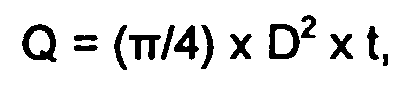
- Defining the optimal diameter based on load-carrying capacity, stiffness and natural frequencies, the diameters of larger tower structures would exceed allowed transportation limitations in terms of vertical and horizontal size. The reasons for requiring larger diameters are to be found in that strength and stiffness increase with the thickness of the steel plate by the power of one, while in relation to the diameter they increase by a power of two and a power of three, respectively. The mathematical explanation, wherein D represents the mean diameter and t is the thickness, being that the load-bearing capacity corresponds to the moment of resistance,

- Increased thickness would mean higher material costs and a requirement for heavier transportation vehicles, be it trucks, trains, ships or helicopters, while diameters need to be small enough to allow for vehicle heights not exceeding typically 4,20 m in order to pass under bridges and through tunnels.
- In order to compromise and take advantage of increased diameters, the too wide sections need to be split along vertical lines, so the shells can be laid down lengthwise with a load height suitable for transportation.
- However, such solution has the disadvantage of claiming a larger amount of manual work on inappropriate places and maybe adding supporting structures to the subparts, which is the reason why this has not been considered a profitable solution.
- It is an object of the invention to provide for a large diameter tower structure for a windmill maintaining or lowering the all-inclusive costs of a structure as installed, and which tower allows for transportation abiding by the typical logistic limitations.
- Another object of the invention is to provide a method of preparing the building elements of a tower and transporting same on a huge trailer after a truck, on a barge after a ship or transport via airborne carriers.
- According to the invention, one these objects is achieved by a steel tower for a windmill, comprising a number of cylindrical or tapered tower sections, at least the wider sections being subdivided into two or more elongated shell segments, which combine into a complete tower section by means of vertical flanges tightened together e.g. by bolts, said shells being also provided with upper and lower horizontal flanges, respectively, to allow interconnection of tower sections one on top of the other.
- Moreover, another advantage of the invention is achieved by a method of building a large size, cylindrical or tapered tower for a windmill, of single-walled steel tower sections from prefabricated shell segments, whereby at least the wider sections are divided into segments along vertical lines and interconnected by flanges provided along the edges thereof, comprising the steps of:
- a) providing two or more tower shell segments from a rolled steel plate having the required radius of curvature, said shells forming in unison a complete circumferential tower section,
- b) providing each shell segment with vertical and horizontal connecting flanges along free edges thereof,
- c) mounting one or more shell segments on a transportation carriage,
- d) transporting said supported segments to the building site,
- e) mounting the shell segments together along their vertical flanges to provide a tower section by connecting means, e.g. bolts,
- f) mounting tower sections on top of each other by connecting them along their opposing horizontal flanges by connecting means, e.g. bolts.
- In an advantageous embodiment of the method, the rolled steel plate constituting a 360° shell is being welded together to form a cylindrical or tapered tower section, whereupon said section is cut into the number of elongated shell segments required.
- In another advantageous embodiment of the method and previous to step a), a number of rolled elongated shell segments are being welded together along their abutting horizontal edges to establish larger lengths of tower shell segments.
- Furthermore, the method will preferably include the flanges in step b) being welded in a position pointing towards the center of the tower. This leaves a smooth outer surface of the tower.
- The vertical flanges are preferably being welded in such distance from the edge of the respective shell that a spacer bar could be sandwiched between the flanges as they are tightened together. A vertical joint visible after interconnecting two neighbour shells via a spacer bar is preferably being covered by inserting a filler material and/or a filler element.
- In a preferred method according to the invention, interconnection of horizontal flanges is performed after offsetting the vertical division lines of neighbour tower sections. Also fitting out each shell with necessary ladders etc. should preferably be performed before transportation to the site, thereby reducing on-site work as much as possible.
- Finally, all parts of the tower structure is preferably being surface treated in the workshop before transportation in order to make the best resistance against the aggressive environmental conditions that often prevail at windmill sites.
- A preferred embodiment of the tower shows that at least one of the tower sections is being divided into three segments of essentially equal arc length, i.e. 120° each.
- In order to provide a satisfactory and practical length of shell segment to be transported, such segment could advantageously be comprised of at least two lengths of segments welded together along their abutting horizontal edges and being fitted with horizontal flanges along the uppermost and lowermost free edges, said flanges being provided with a number of throughholes for interconnecting bolts.
- In an improved embodiment of the invention, the vertical flanges are welded onto the shell segments offset from the corresponding edges by a distance leaving a space between opposing surfaces of flanges for a spacer bar sandwiched between them, as flanges are bolted together, which will allow a strong and secure connection. Said spacer bar could be provided with throughholes matching the holes in the flanges, and preferably each hole in the spacer bar would have a notch extending from the edge of the bar into the hole and wide enough to allow lateral sliding over a bolt.
- A smooth outer surface of the tower is achieved if the vertical and/or horizontal joints between segments and sections, respectively, are being covered by inserting a filler material and/or a filler element.
- A time-saving aspect of operating with shell segments is that they can conveniently be provided with outfitting in the form of e.g. ladder sections and cable fixtures before being transported to the building site.
- The tower according to the invention and the method described to build such tower are offering remarkably economical savings in terms of present and future large diameter towers requested by the wind energy sector, and the towers are immediately operable as they could be fitted out with all installations before leaving the workshop, so they only need to be connected on site.
- An example of an advantageous embodiment of the tower and the method according to the invention is being described below with reference to the accompanying drawings, in which:
- Figure 1 is an elevated side view of one out of three shell segments of a windmill tower section according to the invention, and consisting of several lengths of shells welded together one after the other,
- Figure 2 is a perspective view of a tower section consisting of three segments bolted together in lateral direction,
- Figure 3 is a detailed view of a vertical flange connection inside the tower section, extending perpendicular to the plane of the drawing,
- Figure 4 is a detailed view of horizontal and vertical flanges, respectively, encircled in Figure 2,
- Figure 5 is a cross sectional view showing a tower section comprised of three shell segments, and
- Figure 6 is a shell segment ready for haulage by a truck.
- A shell segment of a windmill tower built according to the invention is shown in Figure 1 and further details are shown in Figures 2-5. The tower comprises a number of shell segments 1 of rolled steel plates, which bolted together side-by-side make up complete circumferential tower sections 2 (see Figures 2 and 5), said sections being secured one on top of another by bolts (see Figures 3 and 4). In Figure 2, a
segment 3 showsseveral lengths 3 of shell welded together along abutting upper and lower edges. Each top and bottom edge of a combined length ofshell segments 3 are provided with aplane flange 4 extending inwardly and carrying a large number ofthroughholes 5 to receive corresponding bolts for tightening sections securely together. - Plane vertical flanges 6 provided with a large number of throughholes 7 are welded in such distance from the edge of the respective shell that an
elongated spacer bar 9 could be sandwiched between the vertical flanges 6, as they are tightened together by means ofbolts 10. - On the outside of the tower,
vertical joints 11 are visible until the joint is filled with a filler material and/or afiller element 12. - In a similar manner, the horizontal joints between sections could be made invisible.
- In a practical embodiment of the method according to the invention, a tower shell segment is equipped with e.g. a ladder section or cable fixtures before being transported to the building site. Such transportation being carried out by placing a shell segment on supports 1, which in turn are placed on a supporting frame or structure 13, preferably being moveable by means of wheels 15 (Figure 6) and a truck (not shown).
- It is obvious that the number of shell segments, into which a section is divided, can be determined considering the limitations imposed by the infrastructure; meaning low bridges, narrow tunnels, etc.
- Further, the choice of connection means is in no way restricted to being bolts and nuts, but they are common and suitable means, especially also in order to take advantage of the prefabricated surface treatment, which should be kept intact.
Claims (16)
- A tower (1) for a windmill, comprising a number of cylindrical or tapered tower sections (2), at least the wider sections (2) of which being subdivided in two or more elongated shell segments (3), which combine into a complete tower section (2), said shell segments being provided with vertical flanges (6), which are tightened together e.g. by bolts (10), characterized in said tower being composed of steel and said shells being also provided with upper and lower horizontal flanges (4), respectively, to allow interconnection of tower sections (2) one on top of the other.
- A steel tower according to claim 1, wherein at least one of the tower sections (2) is being divided into three segments (3) of essentially equal arc length, i.e. 120 ° each.
- A steel tower according to claim 1 or 2, wherein a shell segment (3) comprises at least two lengths of segments (3) welded together along their abutting horizontal edges and being fitted with horizontal flanges (4) along the free uppermost and lowermost edges, said flanges (4) being provided with a number of throughholes (5) for interconnecting bolts.
- A steel tower according to any of the preceding claims, wherein the vertical flanges (6) are welded onto the shell segments (3) offset from the corresponding edges by a distance leaving a space between opposing surfaces of flanges (6) for a spacer bar (9) sandwiched between them, as flanges are bolted together.
- A steel tower according to any of the preceding claims, wherein said spacer bar (9) is provided with throughholes matching the holes in the flanges (6), and preferably each hole in the spacer bar (9) has a notch extending from the edge of the bar (9) into the hole and wide enough to allow lateral sliding of the bar (9) over a bolt (10).
- A steel tower according to any of the preceding claims, wherein the vertical and/or horizontal joints between segments (3) and sections (2), respectively, are being covered by inserting a filler material and/or a filler element (12).
- A steel tower according to any of the preceding claims, wherein a shell segment (3) is provided with fitting out in the form of e.g. a ladder section and cable fixtures before being transported to the building site.
- Method of building a large size, cylindrical or tapered tower (1) for a windmill, of single-walled steel tower sections (2) from prefabricated shell segments (3), whereby at least the wider sections (2) are divided into segments (3) along vertical lines (11) and interconnected by flanges (4,6) provided along the edges thereof, comprising the steps of:a) providing two or more tower shell segments (3) from a rolled steel plate having the required radius of curvature, said shells forming in unison a complete circumferential tower section (2),b) providing each shell segment (3) with vertical and horizontal connecting flanges (6,4) along free edges thereof,c) mounting one or more shell segments (3) on a transportation carriage or supporting frame (13),d) transporting said supported segments (3) to the building site,e) mounting the shell segments (3) together along their vertical flanges (6) to provide one or more tower sections (2) by connecting means (10), e.g. bolts,f) mounting tower sections (2) on top of each other by connecting them along their opposing horizontal flanges (4) by connecting means, e.g. bolts.
- Method according to claim 8, wherein said rolled steel plate in step a) constitutes a 360° shell, which is initially being welded together to form a cylindrical or tapered tower section (2), and then it is cut into the number of elongated shell segments (3) required.
- Method according to claim 8 or 9, wherein previous to step a), an optional number of rolled steel plates in the form of elongated shell segments (3), are being welded together along their abutting horizontal edges to establish larger lengths of tower shell.
- Method according to any preceding method claim, wherein the flanges (4,6) in step b) are being welded in a position pointing towards the center of the tower (1).
- Method according to any of the preceding method claims, wherein the vertical flanges (6) are being welded in such distance from the edge of the respective shell that a spacer bar (9) could be sandwiched between the flanges (6) as they are tightened together.
- Method according to claim 12, wherein a vertical joint (11) visible after interconnecting two neighbour shells via an intermediary spacer bar (9) is being covered by inserting a filler material and/or a filler element (12).
- Method according to any of the preceding method claims, wherein interconnection of horizontal flanges (4) is performed after offsetting the vertical division lines (11) of neighbour tower sections.
- Method according to any of the preceding method claims, wherein fitting out each shell with necessary ladders etc. is performed before transportation to the site.
- Method according to any of the preceding method claims, wherein all parts of the tower structure (1) are being surface treated in the workshop before being transported to the building site.
Applications Claiming Priority (1)
| Application Number | Priority Date | Filing Date | Title |
|---|---|---|---|
| PCT/EP2003/002888 WO2004083633A1 (en) | 2003-03-19 | 2003-03-19 | Method of constructing large towers for wind turbines |
Publications (2)
| Publication Number | Publication Date |
|---|---|
| EP1606514A1 EP1606514A1 (en) | 2005-12-21 |
| EP1606514B1 true EP1606514B1 (en) | 2007-11-07 |
Family
ID=33016796
Family Applications (1)
| Application Number | Title | Priority Date | Filing Date |
|---|---|---|---|
| EP03708258A Revoked EP1606514B1 (en) | 2003-03-19 | 2003-03-19 | Method of constructing large towers for wind turbines |
Country Status (10)
| Country | Link |
|---|---|
| US (1) | US7802412B2 (en) |
| EP (1) | EP1606514B1 (en) |
| CN (1) | CN1759242B (en) |
| AT (1) | ATE377707T1 (en) |
| AU (1) | AU2003212370B2 (en) |
| CA (1) | CA2519277C (en) |
| DE (1) | DE60317372T2 (en) |
| ES (1) | ES2297130T3 (en) |
| PT (1) | PT1606514E (en) |
| WO (1) | WO2004083633A1 (en) |
Cited By (4)
| Publication number | Priority date | Publication date | Assignee | Title |
|---|---|---|---|---|
| DE102011077428A1 (en) | 2011-06-10 | 2012-12-13 | Aloys Wobben | Wind turbine tower |
| DE102012011770A1 (en) * | 2012-06-15 | 2013-12-19 | Siegthalerfabrik Gmbh | Flange part for a tower of a wind turbine |
| EP2692967A2 (en) | 2012-08-04 | 2014-02-05 | e.n.o. energy systems GmbH | Method for erecting a steel tower of a wind energy plant and tower made of steel for a wind energy plant |
| EP4212720A1 (en) * | 2022-01-13 | 2023-07-19 | Bettels Betonfertigteile GmbH | Tower for a wind turbine and corresponding wind turbine |
Families Citing this family (112)
| Publication number | Priority date | Publication date | Assignee | Title |
|---|---|---|---|---|
| DE602005002760T2 (en) * | 2004-02-04 | 2008-07-24 | Corus Staal B.V. | Wind turbine tower, prefabricated metallic wall section for use in this tower, and method of making this tower |
| JP4730792B2 (en) * | 2004-11-10 | 2011-07-20 | ヴェスタス ウィンド システムズ エー/エス | Wind turbine tower part, opening cover device, wind turbine tower part manufacturing method and use thereof |
| CA2591536A1 (en) * | 2004-11-23 | 2006-06-01 | Vestas Wind Systems A/S | A wind turbine, a method for assembling and handling the wind turbine and uses hereof |
| ES2326010B2 (en) * | 2006-08-16 | 2011-02-18 | Inneo21, S.L. | STRUCTURE AND PROCEDURE FOR ASSEMBLING CONCRETE TOWERS FOR WIND TURBINES. |
| DE202007003842U1 (en) * | 2007-03-15 | 2007-05-24 | Mecal Applied Mechanics B.V. | Mast for wind turbine has at least curved sections of prefabricated wall parts in different annular mast sections that are identical, at least in cross-section |
| US20080236073A1 (en) | 2007-03-30 | 2008-10-02 | General Electric Company | Low cost rail-transportable wind turbine tower |
| DE102007018025A1 (en) | 2007-04-17 | 2008-10-23 | Nordex Energy Gmbh | Wind turbine tower |
| WO2009056898A1 (en) * | 2007-11-02 | 2009-05-07 | Alejandro Cortina-Cordero | Post-tensioned concrete tower for wind turbines |
| BRPI0818315B1 (en) * | 2007-10-09 | 2018-06-05 | O. Willis Jeffrey | "Tower Structure, Connection and Mounting Method" |
| EP2047941A1 (en) * | 2007-10-11 | 2009-04-15 | Siemens Aktiengesellschaft | Method for the strengthening of a welded connexion, and/or for the increase of tolerance of a welded connexion in relation to fatigue load ; Element for a tower of a wind turbine ; Tower of a wind turbine and wind turbine |
| DE102008012664A1 (en) | 2008-01-30 | 2009-08-06 | Repower Systems Ag | Wind turbine and a tower or tower segment and a door frame for it |
| DK2252749T3 (en) * | 2008-02-06 | 2018-11-26 | Vestervangen Holding Odense Aps | TOWER ELEMENT |
| US20090223163A1 (en) * | 2008-03-10 | 2009-09-10 | Shu Ching Quek | Wind Turbine Tower Including An Induction Brazed Joint And A Method Of Fabricating The Wind Turbine Tower |
| ES2356679B1 (en) * | 2008-06-06 | 2011-11-28 | Manuel Torres Martinez | TOWER FOR AEROGENERATOR. |
| DE102008029651B3 (en) | 2008-06-24 | 2010-04-08 | Repower Systems Ag | Tower of a wind turbine |
| WO2010055535A1 (en) * | 2008-11-17 | 2010-05-20 | Tecnopali Group S.P.A. | Tubular tower and construction procedure |
| EP2350454B1 (en) * | 2008-11-25 | 2019-01-09 | Vestas Wind Systems A/S | Method of manufacturing a wind turbine tower structure |
| DE102009013186B4 (en) * | 2008-12-19 | 2015-05-28 | Senvion Se | Tower of a wind turbine |
| SE534051C2 (en) * | 2009-02-27 | 2011-04-12 | Roger Ericsson | Prefabricated wall element for tower construction, as well as tower construction |
| US20120012727A1 (en) * | 2009-03-19 | 2012-01-19 | Telefonaktiebolaget Lm Ericsson (Publ) | Tubular Telecom Tower Structure |
| EP2253781B1 (en) * | 2009-05-21 | 2013-03-20 | Alstom Wind Sl | Composite connection for a wind turbine tower structure |
| US20100257739A1 (en) * | 2009-06-30 | 2010-10-14 | Sujith Sathian | Methods and flange for assembling towers |
| US8511013B2 (en) * | 2009-09-03 | 2013-08-20 | General Electric Company | Wind turbine tower and system and method for fabricating the same |
| IT1396433B1 (en) * | 2009-11-16 | 2012-11-23 | Rolic Invest Sarl | WIND POWER PLANT FOR THE GENERATION OF ELECTRICITY AND METHOD TO REALIZE A PILONE OF THE ABOVE WIND FACILITY. |
| CN102834607B (en) * | 2009-12-25 | 2016-07-06 | 苏州可汗极米科技有限公司 | Towers for wind turbines |
| EP2345810B1 (en) * | 2010-01-18 | 2012-11-28 | Siemens Aktiengesellschaft | Arrangement and method of transportation for wind turbine tower segment |
| US10189064B2 (en) | 2010-01-25 | 2019-01-29 | Keystone Tower Systems, Inc. | Control system and method for tapered structure construction |
| US8720153B2 (en) | 2010-01-25 | 2014-05-13 | Keystone Tower Systems, Inc. | Tapered spiral welded structure |
| WO2011110235A2 (en) | 2010-03-12 | 2011-09-15 | Siemens Aktiengesellschaft | Wall portion for a wind turbine tower |
| EP2534376B1 (en) * | 2010-03-12 | 2015-07-29 | Siemens Aktiengesellschaft | Wall portion for a tower of a wind turbine |
| EP2375057B1 (en) * | 2010-03-31 | 2016-05-04 | Siemens Aktiengesellschaft | Wind turbine installation |
| EP2385245B1 (en) | 2010-05-05 | 2017-09-13 | Siemens Aktiengesellschaft | Steel tower for a wind turbine |
| US20110299937A1 (en) * | 2010-06-07 | 2011-12-08 | Jose Pablo Cortina-Ortega | Pre-stressed concrete foundation for a marine building structure |
| DE102010023263A1 (en) * | 2010-06-09 | 2011-12-15 | Repower Systems Ag | Tower for wind energy plant, has tower wall carried out on multiple steel rod segments, where lower steel tube segment is formed as adaptor piece to foundation in installation position |
| CA2805159C (en) | 2010-07-13 | 2018-05-01 | Siemens Aktiengesellschaft | An assembly rig for assembling a wind turbine tower or wind turbine tower sections and a respective method |
| CN103124823B (en) | 2010-07-13 | 2016-05-04 | 安德森塔沃森有限公司 | Use the method for nipple assembling tubular construction structure |
| EP2580468B1 (en) | 2010-07-13 | 2017-11-01 | Siemens Aktiengesellschaft | A lifting and guiding device for handling wind turbine tower sections |
| US8572924B2 (en) * | 2010-07-30 | 2013-11-05 | Production Resource Group, Llc | Truss hub and parts with variable configurations |
| CA2722226A1 (en) * | 2010-08-24 | 2012-02-24 | Mitsubishi Heavy Industries, Ltd. | Wind turbine generator and construction method for wind turbine tower |
| WO2012041677A1 (en) * | 2010-09-30 | 2012-04-05 | Siemens Aktiengesellschaft | Method for connecting a plurality of cylindrical elements of the tower of a wind power plant |
| US9114751B2 (en) | 2010-11-02 | 2015-08-25 | Siemens Aktiengesellschaft | Universal tower transport stand |
| US20110140447A1 (en) * | 2010-11-10 | 2011-06-16 | Ingo Paura | Reinforcement assembly for use with a support tower of a wind turbine |
| KR101242505B1 (en) * | 2010-12-27 | 2013-03-12 | 재단법인 포항산업과학연구원 | Modular type wind power generation tower |
| US8316615B2 (en) * | 2011-01-19 | 2012-11-27 | General Electric Company | Modular tower and methods of assembling same |
| EP2479430B8 (en) * | 2011-01-24 | 2014-11-19 | ALSTOM Renewable Technologies | Method for assembling shell segments for forming tower sections of a hybrid wind turbine tower |
| DE102011003208B4 (en) | 2011-01-26 | 2016-05-25 | Senvion Gmbh | Tower of a wind turbine with electrical conductors |
| US8209913B2 (en) * | 2011-02-01 | 2012-07-03 | Mitsubishi Heavy Industries, Ltd. | Tubular structure and wind turbine generator |
| AT511232B1 (en) * | 2011-03-21 | 2014-09-15 | Andritz Ag Maschf | METHOD FOR PRODUCING A YANKEE CYLINDER |
| AU2012201882B8 (en) * | 2011-04-01 | 2015-08-13 | Axicom Pty Ltd | Standardised Monopole Strengthening |
| WO2012146317A1 (en) * | 2011-04-27 | 2012-11-01 | Uztek Endustri Tesisleri Insaat Imalat Ve Montaj Sanayi Ve Ticaret Limited Sirketi | Tower production method |
| EP2525079A1 (en) * | 2011-05-16 | 2012-11-21 | Siemens Aktiengesellschaft | Method for the production of wind turbine tower segments and wind turbine tower |
| US8245458B2 (en) | 2011-05-17 | 2012-08-21 | General Electric Company | Wind turbine with tower support system and associated method of construction |
| US8915043B2 (en) | 2011-05-25 | 2014-12-23 | General Electric Company | Bolt connection for a wind tower lattice structure |
| EP3974100B1 (en) | 2011-09-20 | 2025-11-26 | Keystone Tower Systems, Inc. | Construction system for manufacturing a tapered structure |
| US8584429B2 (en) * | 2011-09-30 | 2013-11-19 | Tindall Corporation | Tower erection system and method |
| US8393118B2 (en) | 2011-12-22 | 2013-03-12 | General Electric Company | Friction damping bolt connection for a wind tower lattice structure |
| DE102012106772A1 (en) | 2012-07-25 | 2014-01-30 | Thyssenkrupp Steel Europe Ag | Modular tower of a wind turbine |
| US9153853B2 (en) | 2012-08-24 | 2015-10-06 | Wake Skykeeper, Llc | Monopole tower reinforcement configuration and related methods |
| DE102012112415B4 (en) | 2012-12-17 | 2014-08-07 | Thyssenkrupp Steel Europe Ag | Transition body for arrangement between differently executed sections of a wind turbine tower and wind turbine tower with such a transition body |
| USD760165S1 (en) | 2013-07-01 | 2016-06-28 | Marmen Inc | Tower |
| DE102013107059B4 (en) * | 2013-07-04 | 2018-12-06 | SIAG Industrie GmbH | Process for the production and erection of a tubular tower construction |
| US20150027068A1 (en) * | 2013-07-24 | 2015-01-29 | General Electric Company | Tower base assembly for a wind turbine |
| DE102013110495A1 (en) | 2013-09-23 | 2015-03-26 | Thyssenkrupp Steel Europe Ag | Transition body between tower sections of a wind turbine and tower of a wind turbine comprising a transition body |
| DE102013016604A1 (en) | 2013-10-07 | 2015-04-09 | EcoEnterprises GmbH | Steel tube tower of a wind turbine, as well as methods for manufacturing and assembling the tower components |
| DE102013225128A1 (en) | 2013-12-06 | 2015-06-11 | Wobben Properties Gmbh | Wind turbine and wind turbine tower |
| ES2538734B1 (en) * | 2013-12-20 | 2016-05-10 | Acciona Windpower, S.A. | Assembly procedure of concrete towers with a truncated cone section and a concrete tower mounted with said procedure |
| DE202014101245U1 (en) | 2014-03-18 | 2014-04-09 | Planen-Schmitz GmbH | Protection device for covering an opening of a tower of a wind turbine or similar structure |
| EP3132141B1 (en) * | 2014-04-14 | 2018-02-28 | Vestas Wind Systems A/S | Tower segment |
| AU2015246404B2 (en) | 2014-04-14 | 2018-03-29 | Vestas Wind Systems A/S | Tower segment |
| EP3134642B1 (en) | 2014-04-22 | 2019-02-27 | Vestas Wind Systems A/S | Alignment tool, system and method for the connection of wind turbine tower segments |
| EP3134643B1 (en) | 2014-04-22 | 2020-09-23 | Vestas Wind Systems A/S | Method and tool for assembling tower elements |
| WO2015161858A1 (en) * | 2014-04-25 | 2015-10-29 | Vestas Wind Systems A/S | Tower section production process |
| USD776801S1 (en) * | 2014-06-24 | 2017-01-17 | Kobe Steel, Ltd | Heat exchanger tube |
| AU2015330436A1 (en) | 2014-10-06 | 2017-04-27 | Vestas Wind Systems A/S | Hinged tower segments and transport method |
| FR3029231B1 (en) * | 2014-12-01 | 2016-12-30 | Lafarge Sa | CONCRETE SECTION |
| ES2939837T3 (en) | 2014-12-09 | 2023-04-27 | Siag Ind Gmbh | Procedure for erecting tubular tower structure and tubular tower structure |
| DE102015115645A1 (en) | 2015-09-16 | 2017-03-16 | SIAG Industrie GmbH | Process for the production and erection of a tubular tower construction |
| DE102014118251B4 (en) * | 2014-12-09 | 2017-05-04 | SIAG Industrie GmbH | Process for the production and erection of a tubular tower construction |
| PL3277952T3 (en) * | 2015-04-02 | 2019-08-30 | Arcelormittal | Section of wind turbine tower, wind turbine tower and method of assembly |
| DE102015211269A1 (en) | 2015-06-18 | 2016-12-22 | Wobben Properties Gmbh | Wind turbine tower and wind turbine |
| DE102015110344A1 (en) | 2015-06-26 | 2016-12-29 | Eno Energy Systems Gmbh | Section of a tower section, a tower and a method of making a section of a tower section |
| DE102015115646A1 (en) | 2015-09-16 | 2017-03-16 | SIAG Industrie GmbH | Door construction for a tubular tower construction |
| DE102015014458A1 (en) | 2015-09-16 | 2017-03-16 | Senvion Gmbh | Door construction for a tubular tower construction |
| DE102016002372A1 (en) * | 2016-02-19 | 2017-08-24 | Senvion Gmbh | Method for assembling a tubular tower segment |
| DE102016206755A1 (en) | 2016-04-21 | 2017-10-26 | Thyssenkrupp Ag | Transition body for a tower of a wind turbine, tower with these and method for its construction |
| DE102016118549A1 (en) * | 2016-08-02 | 2018-02-08 | Eno Energy Systems Gmbh | A method for separating a shell of at least one tower section of a tower and a portable separation device |
| US9850674B1 (en) | 2016-10-13 | 2017-12-26 | General Electric Company | Vertical joint assembly for wind turbine towers |
| EP3315694A1 (en) * | 2016-10-27 | 2018-05-02 | Siemens Aktiengesellschaft | Tower structure |
| US10053886B2 (en) | 2016-11-29 | 2018-08-21 | General Electric Company | Connection assembly for wind turbine tower |
| CA3066390C (en) * | 2016-12-20 | 2023-12-19 | Titan Trailers Inc. | Cylindrical cargo container construction |
| USD915945S1 (en) | 2016-12-20 | 2021-04-13 | Michael Kloepfer | Cylindrical semi-trailer |
| EP3558849B1 (en) | 2016-12-20 | 2022-09-21 | Michael Kloepfer | Cylindrical semi-trailer |
| DE102017116873A1 (en) | 2017-07-26 | 2019-01-31 | Wobben Properties Gmbh | Wind turbine steel tower ring segment and procedure |
| CA3218391A1 (en) | 2017-09-22 | 2019-03-28 | Titan Trailers Inc. | Quasi-cylindrical cargo container and construction |
| CN107654338B (en) * | 2017-09-30 | 2019-09-03 | 新疆金风科技股份有限公司 | Tower section, tower frame, wind turbine and method for manufacturing tower section |
| DE102017125716A1 (en) * | 2017-11-03 | 2019-05-09 | Eno Energy Systems Gmbh | Method for erecting a tower with a multi-part tower section and sub-section of a multi-part tower section of a tower |
| DE102017011046A1 (en) * | 2017-11-29 | 2019-05-29 | Senvion Gmbh | Tower segment for a wind turbine and method for making a tower segment |
| CN108000076B (en) * | 2017-12-29 | 2024-06-21 | 金风科技股份有限公司 | Manufacturing method of tower section, tower section, tower and wind turbine generator set |
| US10676952B2 (en) | 2018-01-26 | 2020-06-09 | General Electric Company | System and method for stabilizing a wind turbine |
| USD930141S1 (en) * | 2018-06-01 | 2021-09-07 | Durkee Hi-Tech Material (Wuhan) Group Co., Ltd. | Air-duct |
| CN108894930B (en) * | 2018-06-28 | 2019-09-06 | 北京金风科创风电设备有限公司 | Support assembly, assembly tool and assembly method |
| CN109139386B (en) * | 2018-09-30 | 2019-08-23 | 北京金风科创风电设备有限公司 | Tower section, tower, dividing method and wind turbine |
| CN109404224B (en) * | 2018-12-10 | 2024-06-18 | 重庆大学 | A wind turbine hybrid tower based on edge-stiffened composite shell |
| CN111894809B (en) * | 2019-05-06 | 2022-03-04 | 北京天杉高科风电科技有限责任公司 | Assembling tool and assembling method |
| DE102019218358A1 (en) * | 2019-11-27 | 2021-05-27 | Thyssenkrupp Steel Europe Ag | Lattice structure for a tower of a wind turbine and tower of a wind turbine |
| EP3845354B1 (en) | 2019-12-10 | 2024-08-28 | Wobben Properties GmbH | Method of manufacturing segments for a tower, prestressed segment, tower ring, tower and wind turbine |
| EP4232710A4 (en) | 2020-10-24 | 2025-02-05 | Okurogullari, Aydin | MODULAR WIND TOWER |
| CN112879233A (en) * | 2020-12-28 | 2021-06-01 | 山东中车风电有限公司 | Sheet-mounted tower, manufacturing and mounting method and wind turbine generator |
| USD950491S1 (en) * | 2021-02-05 | 2022-05-03 | Charles Bryan | Tower with wind or water rotor generators |
| US12006679B2 (en) | 2021-06-17 | 2024-06-11 | Peter Winters | Building structure and methods of assembly |
| CN116100263B (en) * | 2023-03-08 | 2025-03-18 | 北京星航机电装备有限公司 | A method for preparing a large thin-walled cylinder |
| EP4191056B1 (en) | 2023-03-27 | 2026-01-21 | Wobben Properties GmbH | Method for producing partial shells of a steel tower ring segment of a tower of a wind turbine |
Family Cites Families (11)
| Publication number | Priority date | Publication date | Assignee | Title |
|---|---|---|---|---|
| US1265966A (en) * | 1913-05-17 | 1918-05-14 | Canton Culvert & Silo Company | Silo. |
| US1765946A (en) * | 1928-03-29 | 1930-06-24 | Lou F Knowlton | Tank and joint for forming same |
| DE1031952B (en) * | 1953-12-17 | 1958-06-12 | Aug Kloenne Fa | Strip-shaped casing part of a container and device for producing the casing part |
| US3193129A (en) * | 1963-01-31 | 1965-07-06 | Berkefeld Filter Ges Und Celle | Multiple section container |
| US3561890A (en) * | 1969-06-05 | 1971-02-09 | Martin A Peterson | Windmill tower |
| US3935633A (en) * | 1974-04-16 | 1976-02-03 | Bunker Jack E | Tank fabrication process |
| DE2709114A1 (en) | 1977-03-02 | 1978-09-07 | Zueblin Ag | METHOD FOR MANUFACTURING UNDERGROUND TRANSPORT ROUTES OF LARGE DIAMETERS |
| DE3842026A1 (en) * | 1988-10-15 | 1990-07-19 | Dietrich F W Schiffer | Tower of a highly stable, to the greatest extent vibration-free design, inter alia for wind-driven power plants, of a laminar or sandwich construction using glass-fibre-reinforced plastic or carbon-fibre-reinforced plastic, for extremely heavy loadings at great heights |
| NL1011315C2 (en) * | 1999-02-16 | 2000-08-17 | Janssens & Dieperink B V | Method for manufacturing a silo. |
| US6468008B2 (en) * | 1999-09-30 | 2002-10-22 | Great Lakes Manufacturing, Inc. | Apparatus for constraining the position of logs on a truck or trailer |
| DE20013774U1 (en) * | 2000-08-10 | 2000-11-23 | Arand, Wilfried, 14532 Kleinmachnow | Construction module for the manufacture of bridges, buildings and towers, e.g. for wind turbines |
-
2003
- 2003-03-19 DE DE60317372T patent/DE60317372T2/en not_active Expired - Lifetime
- 2003-03-19 CN CN038261790A patent/CN1759242B/en not_active Expired - Lifetime
- 2003-03-19 PT PT03708258T patent/PT1606514E/en unknown
- 2003-03-19 WO PCT/EP2003/002888 patent/WO2004083633A1/en not_active Ceased
- 2003-03-19 US US10/549,807 patent/US7802412B2/en not_active Expired - Lifetime
- 2003-03-19 AU AU2003212370A patent/AU2003212370B2/en not_active Expired
- 2003-03-19 ES ES03708258T patent/ES2297130T3/en not_active Expired - Lifetime
- 2003-03-19 AT AT03708258T patent/ATE377707T1/en not_active IP Right Cessation
- 2003-03-19 CA CA2519277A patent/CA2519277C/en not_active Expired - Lifetime
- 2003-03-19 EP EP03708258A patent/EP1606514B1/en not_active Revoked
Cited By (9)
| Publication number | Priority date | Publication date | Assignee | Title |
|---|---|---|---|---|
| DE102011077428A1 (en) | 2011-06-10 | 2012-12-13 | Aloys Wobben | Wind turbine tower |
| WO2012168387A3 (en) * | 2011-06-10 | 2013-03-21 | Wobben Properties Gmbh | Wind energy plant tower |
| JP2014516137A (en) * | 2011-06-10 | 2014-07-07 | ヴォッベン プロパティーズ ゲーエムベーハー | Wind turbine tower |
| RU2568594C2 (en) * | 2011-06-10 | 2015-11-20 | Воббен Пропертиз Гмбх | Tower of wind-power plant |
| US9200468B2 (en) | 2011-06-10 | 2015-12-01 | Wobben Properties Gmbh | Wind energy plant tower |
| DE102012011770A1 (en) * | 2012-06-15 | 2013-12-19 | Siegthalerfabrik Gmbh | Flange part for a tower of a wind turbine |
| EP2692967A2 (en) | 2012-08-04 | 2014-02-05 | e.n.o. energy systems GmbH | Method for erecting a steel tower of a wind energy plant and tower made of steel for a wind energy plant |
| DE102012015489A1 (en) | 2012-08-04 | 2014-02-06 | E.N.O. Energy Systems Gmbh | Method of erecting a steel tower of a wind turbine and tower of steel for a wind turbine |
| EP4212720A1 (en) * | 2022-01-13 | 2023-07-19 | Bettels Betonfertigteile GmbH | Tower for a wind turbine and corresponding wind turbine |
Also Published As
| Publication number | Publication date |
|---|---|
| DE60317372T2 (en) | 2008-08-21 |
| WO2004083633A1 (en) | 2004-09-30 |
| ATE377707T1 (en) | 2007-11-15 |
| PT1606514E (en) | 2008-02-15 |
| CA2519277C (en) | 2011-07-12 |
| AU2003212370A1 (en) | 2004-10-11 |
| ES2297130T3 (en) | 2008-05-01 |
| DE60317372D1 (en) | 2007-12-20 |
| CN1759242B (en) | 2010-05-26 |
| US7802412B2 (en) | 2010-09-28 |
| EP1606514A1 (en) | 2005-12-21 |
| CN1759242A (en) | 2006-04-12 |
| AU2003212370B2 (en) | 2009-03-12 |
| CA2519277A1 (en) | 2004-09-30 |
| US20060272244A1 (en) | 2006-12-07 |
Similar Documents
| Publication | Publication Date | Title |
|---|---|---|
| EP1606514B1 (en) | Method of constructing large towers for wind turbines | |
| US10787834B2 (en) | Tower segment handling method and apparatus | |
| US7160085B2 (en) | Wind turbine | |
| CN101328864B (en) | Wind turbine tower and method for constructing a wind turbine tower | |
| US6467118B2 (en) | Modular polymeric matrix composite load bearing deck structure | |
| CA2267228C (en) | Modular polymer matrix composite support structure and methods of constructing same | |
| US20080236073A1 (en) | Low cost rail-transportable wind turbine tower | |
| US10145138B2 (en) | Tower segment handling method and apparatus | |
| US20100162652A1 (en) | Segment for a Tower, Tower Constructed from Tower Segments, Element for a segment for a Tower, Method for the Pre-Assembly of segments for a Tower, Method for the Assembly of a Tower Containing Segments | |
| EP2278157A2 (en) | Rail-transportable wind turbine tower | |
| EP2350454B1 (en) | Method of manufacturing a wind turbine tower structure | |
| DK2350454T3 (en) | PROCEDURE FOR THE PREPARATION OF A WINDMILL TOWER STRUCTURE | |
| CN119491444A (en) | A pier top connection structure and construction method for a composite structure bridge based on steel and concrete | |
| MXPA99003049A (en) | Modular polymer matrix composite support structure and methods of constructing same |
Legal Events
| Date | Code | Title | Description |
|---|---|---|---|
| PUAI | Public reference made under article 153(3) epc to a published international application that has entered the european phase |
Free format text: ORIGINAL CODE: 0009012 |
|
| 17P | Request for examination filed |
Effective date: 20051019 |
|
| AK | Designated contracting states |
Kind code of ref document: A1 Designated state(s): AT BE BG CH CY CZ DE DK EE ES FI FR GB GR HU IE IT LI LU MC NL PT RO SE SI SK TR |
|
| AX | Request for extension of the european patent |
Extension state: AL LT LV MK |
|
| DAX | Request for extension of the european patent (deleted) | ||
| GRAP | Despatch of communication of intention to grant a patent |
Free format text: ORIGINAL CODE: EPIDOSNIGR1 |
|
| GRAS | Grant fee paid |
Free format text: ORIGINAL CODE: EPIDOSNIGR3 |
|
| GRAA | (expected) grant |
Free format text: ORIGINAL CODE: 0009210 |
|
| AK | Designated contracting states |
Kind code of ref document: B1 Designated state(s): AT BE BG CH CY CZ DE DK EE ES FI FR GB GR HU IE IT LI LU MC NL PT RO SE SI SK TR |
|
| REG | Reference to a national code |
Ref country code: GB Ref legal event code: FG4D |
|
| REG | Reference to a national code |
Ref country code: IE Ref legal event code: FG4D |
|
| REG | Reference to a national code |
Ref country code: CH Ref legal event code: EP |
|
| REF | Corresponds to: |
Ref document number: 60317372 Country of ref document: DE Date of ref document: 20071220 Kind code of ref document: P |
|
| REG | Reference to a national code |
Ref country code: PT Ref legal event code: SC4A Free format text: AVAILABILITY OF NATIONAL TRANSLATION Effective date: 20080204 |
|
| REG | Reference to a national code |
Ref country code: GR Ref legal event code: EP Ref document number: 20080400380 Country of ref document: GR |
|
| PG25 | Lapsed in a contracting state [announced via postgrant information from national office to epo] |
Ref country code: LI Free format text: LAPSE BECAUSE OF FAILURE TO SUBMIT A TRANSLATION OF THE DESCRIPTION OR TO PAY THE FEE WITHIN THE PRESCRIBED TIME-LIMIT Effective date: 20071107 Ref country code: SE Free format text: LAPSE BECAUSE OF FAILURE TO SUBMIT A TRANSLATION OF THE DESCRIPTION OR TO PAY THE FEE WITHIN THE PRESCRIBED TIME-LIMIT Effective date: 20080207 Ref country code: CH Free format text: LAPSE BECAUSE OF FAILURE TO SUBMIT A TRANSLATION OF THE DESCRIPTION OR TO PAY THE FEE WITHIN THE PRESCRIBED TIME-LIMIT Effective date: 20071107 |
|
| REG | Reference to a national code |
Ref country code: ES Ref legal event code: FG2A Ref document number: 2297130 Country of ref document: ES Kind code of ref document: T3 |
|
| PG25 | Lapsed in a contracting state [announced via postgrant information from national office to epo] |
Ref country code: BG Free format text: LAPSE BECAUSE OF FAILURE TO SUBMIT A TRANSLATION OF THE DESCRIPTION OR TO PAY THE FEE WITHIN THE PRESCRIBED TIME-LIMIT Effective date: 20080207 Ref country code: SI Free format text: LAPSE BECAUSE OF FAILURE TO SUBMIT A TRANSLATION OF THE DESCRIPTION OR TO PAY THE FEE WITHIN THE PRESCRIBED TIME-LIMIT Effective date: 20071107 |
|
| REG | Reference to a national code |
Ref country code: CH Ref legal event code: PL |
|
| PG25 | Lapsed in a contracting state [announced via postgrant information from national office to epo] |
Ref country code: AT Free format text: LAPSE BECAUSE OF FAILURE TO SUBMIT A TRANSLATION OF THE DESCRIPTION OR TO PAY THE FEE WITHIN THE PRESCRIBED TIME-LIMIT Effective date: 20071107 |
|
| ET | Fr: translation filed | ||
| PG25 | Lapsed in a contracting state [announced via postgrant information from national office to epo] |
Ref country code: CZ Free format text: LAPSE BECAUSE OF FAILURE TO SUBMIT A TRANSLATION OF THE DESCRIPTION OR TO PAY THE FEE WITHIN THE PRESCRIBED TIME-LIMIT Effective date: 20071107 Ref country code: DK Free format text: LAPSE BECAUSE OF FAILURE TO SUBMIT A TRANSLATION OF THE DESCRIPTION OR TO PAY THE FEE WITHIN THE PRESCRIBED TIME-LIMIT Effective date: 20071107 |
|
| PLBI | Opposition filed |
Free format text: ORIGINAL CODE: 0009260 |
|
| PLBI | Opposition filed |
Free format text: ORIGINAL CODE: 0009260 |
|
| PG25 | Lapsed in a contracting state [announced via postgrant information from national office to epo] |
Ref country code: BE Free format text: LAPSE BECAUSE OF FAILURE TO SUBMIT A TRANSLATION OF THE DESCRIPTION OR TO PAY THE FEE WITHIN THE PRESCRIBED TIME-LIMIT Effective date: 20071107 Ref country code: SK Free format text: LAPSE BECAUSE OF FAILURE TO SUBMIT A TRANSLATION OF THE DESCRIPTION OR TO PAY THE FEE WITHIN THE PRESCRIBED TIME-LIMIT Effective date: 20071107 Ref country code: RO Free format text: LAPSE BECAUSE OF FAILURE TO SUBMIT A TRANSLATION OF THE DESCRIPTION OR TO PAY THE FEE WITHIN THE PRESCRIBED TIME-LIMIT Effective date: 20071107 |
|
| PLAX | Notice of opposition and request to file observation + time limit sent |
Free format text: ORIGINAL CODE: EPIDOSNOBS2 |
|
| 26 | Opposition filed |
Opponent name: GAMESA INNOVATION & TECHNOLOGY, S.L. Effective date: 20080806 |
|
| 26 | Opposition filed |
Opponent name: WOBBEN PROPERTIES GMBH Effective date: 20080807 Opponent name: GAMESA INNOVATION & TECHNOLOGY, S.L. Effective date: 20080806 |
|
| PG25 | Lapsed in a contracting state [announced via postgrant information from national office to epo] |
Ref country code: MC Free format text: LAPSE BECAUSE OF NON-PAYMENT OF DUE FEES Effective date: 20080331 |
|
| NLR1 | Nl: opposition has been filed with the epo |
Opponent name: WOBBEN PROPERTIES GMBH Opponent name: GAMESA INNOVATION & TECHNOLOGY, S.L. |
|
| PLAF | Information modified related to communication of a notice of opposition and request to file observations + time limit |
Free format text: ORIGINAL CODE: EPIDOSCOBS2 |
|
| PLBP | Opposition withdrawn |
Free format text: ORIGINAL CODE: 0009264 |
|
| PG25 | Lapsed in a contracting state [announced via postgrant information from national office to epo] |
Ref country code: IE Free format text: LAPSE BECAUSE OF NON-PAYMENT OF DUE FEES Effective date: 20080319 Ref country code: EE Free format text: LAPSE BECAUSE OF FAILURE TO SUBMIT A TRANSLATION OF THE DESCRIPTION OR TO PAY THE FEE WITHIN THE PRESCRIBED TIME-LIMIT Effective date: 20071107 |
|
| PG25 | Lapsed in a contracting state [announced via postgrant information from national office to epo] |
Ref country code: FI Free format text: LAPSE BECAUSE OF FAILURE TO SUBMIT A TRANSLATION OF THE DESCRIPTION OR TO PAY THE FEE WITHIN THE PRESCRIBED TIME-LIMIT Effective date: 20071107 |
|
| PLBB | Reply of patent proprietor to notice(s) of opposition received |
Free format text: ORIGINAL CODE: EPIDOSNOBS3 |
|
| PG25 | Lapsed in a contracting state [announced via postgrant information from national office to epo] |
Ref country code: CY Free format text: LAPSE BECAUSE OF FAILURE TO SUBMIT A TRANSLATION OF THE DESCRIPTION OR TO PAY THE FEE WITHIN THE PRESCRIBED TIME-LIMIT Effective date: 20071107 |
|
| PG25 | Lapsed in a contracting state [announced via postgrant information from national office to epo] |
Ref country code: HU Free format text: LAPSE BECAUSE OF FAILURE TO SUBMIT A TRANSLATION OF THE DESCRIPTION OR TO PAY THE FEE WITHIN THE PRESCRIBED TIME-LIMIT Effective date: 20080508 Ref country code: LU Free format text: LAPSE BECAUSE OF NON-PAYMENT OF DUE FEES Effective date: 20080319 |
|
| PG25 | Lapsed in a contracting state [announced via postgrant information from national office to epo] |
Ref country code: TR Free format text: LAPSE BECAUSE OF FAILURE TO SUBMIT A TRANSLATION OF THE DESCRIPTION OR TO PAY THE FEE WITHIN THE PRESCRIBED TIME-LIMIT Effective date: 20071107 |
|
| RDAF | Communication despatched that patent is revoked |
Free format text: ORIGINAL CODE: EPIDOSNREV1 |
|
| RDAG | Patent revoked |
Free format text: ORIGINAL CODE: 0009271 |
|
| STAA | Information on the status of an ep patent application or granted ep patent |
Free format text: STATUS: PATENT REVOKED |
|
| PGFP | Annual fee paid to national office [announced via postgrant information from national office to epo] |
Ref country code: NL Payment date: 20110329 Year of fee payment: 9 Ref country code: PT Payment date: 20110222 Year of fee payment: 9 |
|
| 27W | Patent revoked |
Effective date: 20101209 |
|
| GBPR | Gb: patent revoked under art. 102 of the ep convention designating the uk as contracting state |
Effective date: 20101209 |
|
| REG | Reference to a national code |
Ref country code: PT Ref legal event code: MP4A Effective date: 20110601 |
|
| REG | Reference to a national code |
Ref country code: DE Ref legal event code: R138 Ref document number: 20321855 Country of ref document: DE Free format text: GERMAN DOCUMENT NUMBER IS 60317372 Ref country code: DE Ref legal event code: R138 Ref document number: 60317372 Country of ref document: DE Free format text: GERMAN DOCUMENT NUMBER IS 60317372 |
|
| PGFP | Annual fee paid to national office [announced via postgrant information from national office to epo] |
Ref country code: GR Payment date: 20110329 Year of fee payment: 9 |
|
| PGFP | Annual fee paid to national office [announced via postgrant information from national office to epo] |
Ref country code: FR Payment date: 20110408 Year of fee payment: 9 Ref country code: ES Payment date: 20110323 Year of fee payment: 9 Ref country code: DE Payment date: 20110325 Year of fee payment: 9 Ref country code: GB Payment date: 20110325 Year of fee payment: 9 |
|
| PGFP | Annual fee paid to national office [announced via postgrant information from national office to epo] |
Ref country code: IT Payment date: 20110328 Year of fee payment: 9 |