EP1612583B1 - Dispositif et méthode pour la lecture des informations radiographiques à partir d'une couche de phosphore - Google Patents
Dispositif et méthode pour la lecture des informations radiographiques à partir d'une couche de phosphore Download PDFInfo
- Publication number
- EP1612583B1 EP1612583B1 EP04103050A EP04103050A EP1612583B1 EP 1612583 B1 EP1612583 B1 EP 1612583B1 EP 04103050 A EP04103050 A EP 04103050A EP 04103050 A EP04103050 A EP 04103050A EP 1612583 B1 EP1612583 B1 EP 1612583B1
- Authority
- EP
- European Patent Office
- Prior art keywords
- signal values
- detector signal
- light beam
- phosphor layer
- storage phosphor
- Prior art date
- Legal status (The legal status is an assumption and is not a legal conclusion. Google has not performed a legal analysis and makes no representation as to the accuracy of the status listed.)
- Expired - Lifetime
Links
- OAICVXFJPJFONN-UHFFFAOYSA-N Phosphorus Chemical compound [P] OAICVXFJPJFONN-UHFFFAOYSA-N 0.000 title claims abstract description 50
- 238000000034 method Methods 0.000 title claims description 24
- 230000000638 stimulation Effects 0.000 claims description 53
- 238000003860 storage Methods 0.000 claims description 50
- 238000005070 sampling Methods 0.000 claims description 15
- 238000012545 processing Methods 0.000 claims description 14
- 238000009795 derivation Methods 0.000 claims description 10
- 230000008569 process Effects 0.000 claims description 9
- 238000012935 Averaging Methods 0.000 claims description 7
- 239000002184 metal Substances 0.000 claims description 4
- 229910052751 metal Inorganic materials 0.000 claims description 4
- 239000000463 material Substances 0.000 claims description 2
- 230000001678 irradiating effect Effects 0.000 claims 2
- 230000003287 optical effect Effects 0.000 description 5
- 238000004364 calculation method Methods 0.000 description 4
- 238000013461 design Methods 0.000 description 4
- 238000001514 detection method Methods 0.000 description 4
- 230000000694 effects Effects 0.000 description 2
- 230000006870 function Effects 0.000 description 2
- 230000010354 integration Effects 0.000 description 2
- RYGMFSIKBFXOCR-UHFFFAOYSA-N Copper Chemical compound [Cu] RYGMFSIKBFXOCR-UHFFFAOYSA-N 0.000 description 1
- 230000004075 alteration Effects 0.000 description 1
- 230000006399 behavior Effects 0.000 description 1
- 239000004020 conductor Substances 0.000 description 1
- 238000010276 construction Methods 0.000 description 1
- 229910052802 copper Inorganic materials 0.000 description 1
- 239000010949 copper Substances 0.000 description 1
- 230000006735 deficit Effects 0.000 description 1
- 238000010586 diagram Methods 0.000 description 1
- 230000002996 emotional effect Effects 0.000 description 1
- 238000011156 evaluation Methods 0.000 description 1
- 239000003365 glass fiber Substances 0.000 description 1
- 238000012432 intermediate storage Methods 0.000 description 1
- 230000000873 masking effect Effects 0.000 description 1
- 239000013307 optical fiber Substances 0.000 description 1
- 238000012805 post-processing Methods 0.000 description 1
- 230000005855 radiation Effects 0.000 description 1
- 230000009467 reduction Effects 0.000 description 1
- 230000002441 reversible effect Effects 0.000 description 1
- 230000001360 synchronised effect Effects 0.000 description 1
- 229920003002 synthetic resin Polymers 0.000 description 1
- 239000000057 synthetic resin Substances 0.000 description 1
- 230000009897 systematic effect Effects 0.000 description 1
- 230000002123 temporal effect Effects 0.000 description 1
Images
Classifications
-
- G—PHYSICS
- G01—MEASURING; TESTING
- G01T—MEASUREMENT OF NUCLEAR OR X-RADIATION
- G01T1/00—Measuring X-radiation, gamma radiation, corpuscular radiation, or cosmic radiation
- G01T1/16—Measuring radiation intensity
- G01T1/20—Measuring radiation intensity with scintillation detectors
- G01T1/2012—Measuring radiation intensity with scintillation detectors using stimulable phosphors, e.g. stimulable phosphor sheets
- G01T1/2014—Reading out of stimulable sheets, e.g. latent image
-
- G—PHYSICS
- G03—PHOTOGRAPHY; CINEMATOGRAPHY; ANALOGOUS TECHNIQUES USING WAVES OTHER THAN OPTICAL WAVES; ELECTROGRAPHY; HOLOGRAPHY
- G03B—APPARATUS OR ARRANGEMENTS FOR TAKING PHOTOGRAPHS OR FOR PROJECTING OR VIEWING THEM; APPARATUS OR ARRANGEMENTS EMPLOYING ANALOGOUS TECHNIQUES USING WAVES OTHER THAN OPTICAL WAVES; ACCESSORIES THEREFOR
- G03B42/00—Obtaining records using waves other than optical waves; Visualisation of such records by using optical means
- G03B42/02—Obtaining records using waves other than optical waves; Visualisation of such records by using optical means using X-rays
Definitions
- the invention relates to a device and to a corresponding method for reading out X-ray information stored in a storage phosphor layer according to the preamble of claims 1 and 12, respectively.
- X-ray images can be stored in so-called storage phosphors, whereby the X-ray radiation passing through an object, for example a patient, is stored as a latent image in a storage phosphor layer.
- the storage phosphor layer is irradiated with stimulation light and thereby stimulated to emit emission light.
- the emission light whose intensity corresponds to the image stored in the storage phosphor layer is detected by an optical detector and converted into electrical signals.
- the electrical signals are further processed as needed and finally provided for evaluation, in particular for medical diagnostic purposes, by being connected to a corresponding output device, such. As a monitor or printer.
- US Pat. No. 4,484,073 describes an apparatus and a method in which a laser beam is deflected by means of a galvanometer mirror in such a way that the laser beam strikes the storage phosphor layer to be read in a substantially point-like manner and sweeps it over in a line-shaped area.
- the document US 4,943,871 also discloses a similar device. The emission light emitted from the storage phosphor layer in this case is detected by a photomultiplier and converted into an electrical signal.
- a successive readout of individual line-shaped regions of the storage phosphor layer is achieved so that finally a two-dimensional X-ray image is obtained, which is composed of individual lines, which in turn each comprise a multiplicity of individual image points.
- a position reference pulse is generated by means of a so-called linear encoder for each pixel of a line and integrates the electrical signal of the photomultiplier respectively after a position reference pulse over a fixed time interval. The signal value obtained in the respective integration is assigned to the corresponding pixel.
- the speed of the deflection element is generally subject to fluctuations, the speed of the laser beam is not constant over the entire line to be read, ie the laser beam sweeps different widths of the storage phosphor layer within the predetermined, fixed time interval after a position reference pulse, depending on the instantaneous speed.
- This has the consequence that in the described integration of the electrical signal of the photomultiplier generally different width ranges are detected.
- a high instantaneous speed of the laser beam causes a relatively wide subarea of the area corresponding to a pixel to be scanned by the laser beam in the predetermined time interval.
- a low instantaneous velocity results in detection of a relatively narrow portion of the pixel-associated region of the line. Overall, therefore, a partial loss of information and thus an impairment of the image quality of the retrieved X-ray image must be accepted.
- a processing device is provided which is designed to derive a multiplicity of detector signal values from the detector signal and to derive image signal values from detector signal values derived in each case between two, in particular successive, reference time points.
- the invention is based on the idea of detecting the times at which the stimulation light beam is at two or more reference positions by means of two or more sensors, and the detector signal values derived between the detected times from the detector signal to the individual pixels located between the respective reference positions Assign X-ray image. From the, in each case one pixel associated, generally a plurality of detector signal values, an image signal value belonging to the respective pixel is then calculated. In comparison with the method known from the prior art, in the derivation of the individual image signal values according to the invention, a larger proportion of the information acquired during scanning of the line is taken into account.
- Information loss compared with the devices and methods known from the prior art is thus reduced by the device or the method according to the invention.
- dislocations of individual read lines of the X-ray image relative to each other, which of statistical or systematic wow and flutter of the stimulation light beam can be reduced in a simple and reliable manner.
- the device according to the invention and the corresponding method thus allow an increase in the image quality with a simultaneous loss of information.
- a first sensor such that a first reference time can be detected before the movement of the stimulation light beam along the line
- a second sensor such that a second reference time after the movement of the stimulation light beam along the line can be detected.
- the first sensor in the region of an initial and the second sensor in the region of one end of the read line of the storage phosphor layer, preferably in each case in the immediate vicinity of the storage phosphor layer, arranged.
- the stimulation light beam then impinges immediately before and immediately after scanning the line to be read on the first or second sensor.
- the first and / or second sensor can also be arranged in such a way that the stimulation light beam strikes the first or second sensor for a specific period of time before or after the movement along the line.
- the reference times can then be calculated simply by adding or subtracting the respective time interval to the time detected by the first sensor or by the time detected by the second sensor.
- the two sensors need not be arranged in the immediate vicinity of the storage phosphor layer, but can be positioned depending on the available space in the device. In particular, the two sensors need not be positioned in the plane of the storage phosphor layer.
- a further variant of the invention provides that, as an alternative or in addition to the first and second sensors, a plurality of sensors are arranged along one sensor line and can detect a plurality of reference times during the movement of the stimulation light beam along the sensor line, and the processing device for deriving image signal values from the respectively between the two Reference times derived detector signal values is formed. This ensures a particularly accurate and reliable avoidance of image errors.
- the reference times are preferably already detected and stored prior to the actual readout of the storage phosphor layer and only used for a subsequent readout of the storage phosphor layer for deriving the individual image signal values from the detector signal values.
- the detected reference times in this case reflect the characteristic speed fluctuations of the deflection element or of the laser beam during its movement over the line.
- the sensor line is placed at the location where the storage phosphor layer is located during readout. After the detection of the reference times, which preferably takes place shortly before the readout of the storage phosphor layer, the sensor line is removed, and the storage phosphor layer to be read can then be guided past the line-shaped laser beam for reading.
- the sensors are each provided with a slit diaphragm, through which at least a part of the stimulation light beam can pass and hit the respective sensor. Due to the slit diaphragms, a particularly accurate detection of the individual reference times is achieved.
- a printed circuit board is provided on which the sensors are mounted and which comprises the respective slit diaphragms. This achieves a simple and compact construction.
- a further preferred embodiment of this variant is that the circuit board for the light of the stimulation light beam is at least partially permeable.
- the individual slit diaphragms in this embodiment are preferably located on the side of the printed circuit board facing the incident stimulation light beam.
- the slit diaphragms can also be located on the side of the printed circuit board facing away from the incident stimulation light beam.
- the slit diaphragms are preferably made of a material substantially impermeable to the light of the stimulation light beam, such as metal.
- the sensors are arranged in the region of the individual slit diaphragms which can detect at least part of the stimulation light beam passing through the individual slit diaphragms and the printed circuit board.
- the sensors are in this case preferably constructed such that their respective photosensitive surface faces the printed circuit board.
- the image signal values are respectively derived by forming a, in particular arithmetic, average value from a plurality of detector signal values.
- the averaging provides a simple, efficient and particularly reliable way of calculating the image signal values from the respective detector signal values
- arithmetic mean By forming the arithmetic mean, a high image quality is achieved.
- the number of detector signal values, from which in each case an image signal value is derived is determined from the detected reference times. In particular, in conjunction with a subsequent averaging a high image sharpness is achieved.
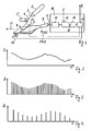
- a stimulation light beam 3 is generated by a laser 2, which is deflected by a deflection element 4 rotated by a motor 5 in such a way that it travels along a line 8 over the storage phosphor layer 1 to be read out emotional.
- the storage phosphor layer 1 emits emission light as a function of the x-ray information stored therein, which is collected by an optical collecting device 6, for example an optical fiber bundle, and detected by an optical detector 7, preferably a photomultiplier, and thereby converted into a corresponding detector signal S.
- the deflector 4 is preferably formed as a mirror, such as e.g. as a polygon mirror or galvanometer mirror.
- the detector signal S is supplied to a processing device 16, in which image signal values B for individual pixels of the read-out X-ray image are derived. If the read-out line 8 is to be composed, for example, of 1000 pixels, then corresponding image signal values B are derived from the detector signal S 1000 obtained when reading out the line 8.
- a successive readout of individual lines 8 is achieved and thus a two-dimensional X-ray image consisting of individual pixels each having an associated image signal value B is obtained. If the number of lines 8 read out in the transport direction T is, for example, 1500, a total of 1500 ⁇ 1000 pixels each having an associated image signal value B are obtained with 1000 pixels per line for the X-ray image read.
- FIG. 2 shows an exemplary course of the detector signal S generated in the device according to FIG. 1.
- the derivation of image signal values B from the detector signal S according to the invention is explained in more detail below.
- the detector signal S is first (see FIG. 1) filtered by a low-pass filter 12, wherein higher-frequency components of the detector signal S, in particular noise components, are eliminated.
- the filtered detector signal S is then fed to an analog-to-digital converter 13 and sampled there at a sampling frequency f, a detector signal value D being obtained in each digital unit in each sampling operation.
- the sampling of the detector signal S in the analog-to-digital converter 13 is preferably carried out according to the so-called. Sample and hold principle, after which the respective current analog signal height of the present at a sampling time at the analog-to-digital converter 13 detector signal S and held in a corresponding digital detector signal value D is converted.
- the image signal values B are calculated in a computing unit 15 from the detector signal values D.
- the low-pass filter 12 is preferably designed such that are eliminated by these portions of the detector signal S, which have a frequency f g , which is greater than half the sampling frequency f: f g > 0.5 ⁇ f. As a result, any image artifacts generated by the scanning of high-frequency detector signal components are avoided, thereby further improving the image quality.
- FIG. 3 shows a plurality of detector signal values D derived from the detector signal S shown in FIG. 2 over time t.
- the time interval of the individual detector signal values D to each other is determined by the sampling frequency f of the analog-to-digital converter 13. At each point in time, this corresponds to a specific location of the stimulation light beam 3 on the line 8 of the storage phosphor layer 1.
- the sampling frequency f is chosen so that at least two detector signal values B are obtained for each individual pixel along the line 8, from which then an image signal value belonging to each pixel is calculated can. For simplification and better clarity, it is assumed in this example that the read-out line 8 should consist of only 13 pixels.
- the sampling frequency f is chosen in this example so that five detector signal values D were obtained for each of the 13 pixels.
- the image signal values B correspondingly derived for this example are shown in FIG. 4, wherein an image signal value B was calculated from in each case five of the detector signal values D shown in FIG. 3 by determining the arithmetic average from the individual detector signal values D.
- the sampling frequency f in this example is five times the reciprocal of a mean time duration .DELTA.t which the stimulation light beam 3 requires in the time average for the movement over a pixel of the x-ray image along the line 8.
- the image signal value B of a pixel is also advantageous to calculate the image signal value B of a pixel from the respective detector signal values D immediately after deriving these detector signal values D from the detector signal S.
- the individual image signal values B of the line 8 are thus determined temporally parallel or simultaneously with the scanning of the line 8.
- the calculation of a single pixel always takes place immediately after deriving the two or more detector signal values D required for the calculation of the respective image signal values B. From this, only the detector signal values D to be combined into one image signal value B are stored in the memory 14 of the processing device 16 before being further processed in the computing unit 15. The storage requirement in the memory 14 is thereby low.
- a post-processing of the detector signal values D after the end of the read-out of the line 8 can be omitted.
- the repeated sampling of the detector signal S for each individual pixel which is also referred to as oversampling, and the derivation of a corresponding image signal value for each pixel of the row 8 from a plurality of detector signal values leads overall to a reduction of the noise superimposed on the detector signal S and thus to an improved one Image quality with lower information losses compared to the known from the prior art devices and methods.
- the signal processing of the detector signal S explained in more detail in connection with FIGS. 2 to 4 is particularly suitable for scanners with good synchronization properties, in which the stimulation light beam 3 is moved at substantially constant speed over the respective row 8 of the storage phosphor layer 1 to be read. This is usually achieved by optically high-quality deflection elements 4, in particular galvanometer or polygon mirror, in conjunction with a motor 5 with good synchronization properties.
- the processing of the detector signal S described in more detail below is preferably performed.
- the corresponding device (see FIG. 1) has two sensors 10 and 11, which are arranged in the region of the beginning or end of line 8, along which the stimulation light beam 3 moves.
- the stimulation light beam 3 is deflected with the deflection element 4 in the direction of the line 8, then this passes through the first sensor 10 before scanning the line 8 and the second sensor 11 after scanning the line 8.
- the light of the stimulation light beam 3 is from the two light-sensitive sensors 10 and 11 detected and in corresponding electrical pulses P (t1) and P (t2) to the Reference times t1 and t2 converted and forwarded to a computing unit 15 of the processing device 16.
- the detector signal S obtained during the movement of the stimulation light beam 3 via the line 8 of the storage phosphor layer 1 is, as already explained, filtered by a low-pass filter 12 and sampled in an analog-to-digital converter 13 at a sampling frequency f, wherein a plurality of detector signal values D. is obtained.
- the detector signal values D are buffered in a memory 14.
- the arithmetic unit 15 accesses the detector signal values D latched in the memory 14 and derives therefrom individual image signal values B.
- the derivation of the image signal values B in particular the assignment of individual detector signal values D to one pixel and the calculation of the image signal value from the associated detector signal values D, takes place in this variant of the signal processing as a function of the reference times t1 and t2.
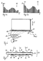
- FIG. 5a shows a first example of detector signal values D over time t, which were derived from the detector signal S for one line 8.
- the two reference times t1 and t2 are entered in the diagram, to which the stimulation light beam 3 passes the two sensors 10 and 11, respectively.
- the detector signal values D relevant for a derivation of image signal values B for the individual pixels of the X-ray image along line 8 lie between the two reference times t1 and t2. Accordingly, only these detector signal values D are used for the derivation of the individual image signal values B.
- the detector signal values D shown in FIG. 5 b are determined by way of example for a further line 8.
- the second reference time t2 is only reached at a later point in time compared to the example shown in FIG. 5a. This is due to tracking variations of the stimulation light beam 3 during its movement along line 8. In terms of time, the stimulation light beam 3 sweeps over the in this case at a speed which is lower than in the example shown in Fig. 5a.
- the detector signal values D detected in each case between the two reference times t1 and t2 are distributed to the predetermined number of individual pixels. If one row 8 of the X-ray image to be read comprises, for example, 1000 pixels, and 5000 detector signal values D are derived between the two reference times t1 and t2 in the example shown in FIG. 5a, then each detector pixel is assigned five detector signal values and from the respectively assigned detector signal values Image signal value calculated, in particular by averaging.
- Such an averaging can be done, for example, from a corresponding weighting of non-integer portions of the detector signal values D. For example, in such an averaging for the first image signal value in the example of FIG. 5b, five detector signal values of 100% each and the subsequent sixth detector signal value of only 10% would be weighted.
- individual detector signal values can always be assigned completely to individual pixels.
- FIG. 5b it would be conceivable, for example, to assign in each case nine adjacent pixels to five detector signal values D and to the respectively following tenth pixel assign six detector signal values. All further assignments of detector signal values D to pixels are then carried out accordingly.
- a method for further improving the image quality provides for detecting the temporal behavior of the movement of the stimulation light beam along a line and for taking this into account in the derivation of image signal values B from the individual detector signal values D.
- FIG. 6 shows a preferred embodiment of a corresponding device for carrying out this method.
- the stimulation light beam 3 generated by a laser 2 is deflected by a rotating polygon mirror 20 and strikes a sensor line 30 after passing through a suitable optical system, which consists in the example shown of a lens 21 and a cylindrical mirror 22.
- the sensor line 30 has a plurality of regular spaced apart photosensitive sensors 34. During the movement of the stimulation light beam 3 along the sensor line 30, the latter successively passes over the individual sensors 34. In each case, a pulse P (ti) is generated at a reference time ti which is forwarded to a processing device (not shown).
- the sensor line 30 may be positioned in the plane of the storage phosphor layer 1, but alternatively also at a short distance in front of or behind the plane of the storage phosphor layer 1.
- a multiplicity of reference times ti are detected during at least one complete 360 ° rotation of the polygonal mirror and in the Processing device stored.
- the sensor line 30 can then be removed from the beam path, for example by a suitable mechanical pivoting device (not shown). If the sensor line 30 is arranged at a small distance behind the storage phosphor layer 1, it can remain in its position and is concealed by the latter when the storage phosphor layer 1 is read out.
- the actual read-out process of the storage phosphor layer 1 can now begin by being guided past the beam path along the transport direction T. If, as already explained in connection with FIGS. 1, 5a and 5b, a first and second reference time t1 and t2 are respectively detected by means of the two sensors 10 and 11, the assignment of the detector signal values obtained between the two reference times t1 and t2 D to individual pixels with simultaneous consideration of the previously recorded reference times ti done. The corresponding image signal values B are then derived from the assigned detector signal values D.
- FIG. 7 shows a cross section (section) through the sensor line 30 shown in FIG. 6.
- the sensor line 30 comprises a printed circuit board 31, which consists of synthetic resin reinforced with glass fibers and is at least partially transparent to the light of the stimulation light beam 3.
- individual slit diaphragms 33 are produced by masking a metal layer 32 thereon, which preferably consists of copper.
- the sensors 34 are mounted in each case in the region of the slit diaphragms 33, which have a photosensitive layer 36 on the side facing the printed circuit board 31.
- the sensors 34 are connected to conductor tracks 35 located on the printed circuit board 31 and connected accordingly, for example via a parallel circuit.
- Particularly suitable as sensors 34 are photodiodes in SMD design, such as, for example, the type BPW34 reverse gullwing from Osram.
- This embodiment of the sensor line 30 achieves a particularly simple, compact and reliable detection of the reference times ti along the sensor line 30.
- a particularly high image quality is achieved.
Landscapes
- Physics & Mathematics (AREA)
- General Physics & Mathematics (AREA)
- Health & Medical Sciences (AREA)
- Life Sciences & Earth Sciences (AREA)
- High Energy & Nuclear Physics (AREA)
- Molecular Biology (AREA)
- Spectroscopy & Molecular Physics (AREA)
- Facsimile Scanning Arrangements (AREA)
- Image Input (AREA)
- Conversion Of X-Rays Into Visible Images (AREA)
Claims (17)
- Dispositif destiné à la lecture d'une information radiographique mémorisée dans une couche de mémorisation à base de phosphore (1), avec lequel est obtenue une image radiographique constituée d'une multitude de points d'image, comportant :- un dispositif d'exposition (2, 4, 5, 20 - 22) pour exposer la couche de mémorisation à base de phosphore (1) à un faisceau de lumière de stimulation (3) pouvant être déplacé au-dessus de la couche de mémorisation à base de phosphore (1) le long d'une ligne (8), et pouvant en l'occurrence stimuler la couche de mémorisation à base de phosphore (1) à émettre de la lumière d'émission,- un détecteur (7) pour détecter de la lumière d'émission émise par la couche de mémorisation à base de phosphore (1), et pour convertir la lumière d'émission détectée en un signal de détection (S) correspondant, et- un dispositif de traitement (16) destiné à dériver du signal de détection (S) des valeurs de signaux d'image (B) pour les points d'image de l'image radiographique le long de la ligne (8),caractérisé en ce que- il est prévu au moins deux détecteurs (10, 11, 34) qui sont disposés sur différentes positions de référence, et qui peuvent détecter au moins deux moments de référence (t1, t2, ti) auxquels le faisceau de lumière de stimulation (3) se trouve sur les différentes positions de référence, et- en ce que le dispositif de traitement (16) est agencé pour dériver du signal de détection (S) une pluralité de valeurs de signaux de détection (D), et pour dériver des valeurs de signaux d'image (B) à partir de valeurs de signaux de détection (D) dérivées entre deux moments de référence (t1, t2, ti) respectifs.
- Dispositif selon la revendication 1, caractérisé en ce qu'un premier détecteur (10) est disposé de telle sorte qu'un premier moment de référence (t1) puisse être détecté avant le déplacement du faisceau de lumière de stimulation (3) le long de la ligne (8), et en ce qu'un deuxième détecteur (11) est disposé de telle sorte qu'un deuxième moment de référence (t2) puisse être détecté après le déplacement du faisceau de lumière de stimulation (3) le long de la ligne (8).
- Dispositif selon la revendication 2, caractérisé en ce que le premier détecteur (10) est disposé dans la zone d'un début, et le deuxième détecteur (11) dans la zone d'une fin de la ligne (8).
- Dispositif selon la revendication 2 ou 3, caractérisé en ce que le premier et/ou le deuxième détecteur (t1 ou t2) sont disposés de telle sorte que le faisceau de lumière de stimulation (3) arrive sur le premier ou le deuxième détecteur (10 ou 11) un certain laps de temps avant ou après le déplacement le long de la ligne (8).
- Dispositif selon la revendication 1, caractérisé en ce que- plusieurs détecteurs (34) sont disposés le long d'une ligne de détection (30), lesquels sont en mesure de détecter plusieurs moments de référence (ti) pendant le déplacement du faisceau de lumière de stimulation (3) le long de la ligne de détection (30), et- en ce que le dispositif de traitement (16) est agencé pour dériver des valeurs de signaux d'image (B) des valeurs de signaux de détection (D) dérivées entre deux moments de référence (ti) respectifs.
- Dispositif selon l'une des revendications 1 à 5, caractérisé en ce que chacun des détecteurs (34) est doté d'un diaphragme à fente (33), à travers lequel peut passer au moins une partie du faisceau de lumière de stimulation (3), laquelle peut être détectée par le détecteur (34) respectif.
- Dispositif selon la revendication 6, caractérisé en ce qu'il est prévu une carte de circuits imprimés (31) sur laquelle sont disposés les détecteurs (34), et qui inclut les diaphragmes à fente (33) respectifs.
- Dispositif selon la revendication 7, caractérisé en ce que la carte de circuits imprimés (31) est au moins partiellement perméable à la lumière du faisceau de lumière de stimulation (3), et en ce que les différents diaphragmes à fente (33) sont situés sur la face de la carte de circuits imprimés (31) qui est orientée vers le faisceau incident de lumière de stimulation (3).
- Dispositif selon la revendication 8, caractérisé en ce que les diaphragmes à fente (33) sont constitués d'un matériau qui est sensiblement imperméable à la lumière du faisceau de lumière de stimulation (3), notamment de métal.
- Dispositif selon l'une des revendications 7 à 9, caractérisé en ce que les détecteurs (34) sont disposés dans la zone des différents diaphragmes à fente (33), sur la face de la carte de circuits imprimés (31) qui est opposée au faisceau incident de lumière de stimulation (3).
- Dispositif selon la revendication 10, caractérisé en ce que les détecteurs (34), qui sont notamment réalisés sous la forme de photodiodes, comportent chacun une surface photosensible (36), qui est orientée vers la carte de circuits imprimés (31).
- Procédé destiné à la lecture d'une information radiographique mémorisée dans une couche de mémorisation à base de phosphore (1), avec lequel est obtenue une image radiographique constituée d'une multitude de points d'image, comportant les étapes suivantes :- exposition de la couche de mémorisation à base de phosphore (1) à un faisceau de lumière de stimulation (3), qui est déplacé au-dessus de la couche de mémorisation à base de phosphore (1) le long d'une ligne (8), et peut en l'occurrence stimuler la couche de mémorisation à base de phosphore (1) à émettre de la lumière d'émission,- détection de la lumière d'émission émise par la couche de mémorisation à base de phosphore (1), et conversion de la lumière d'émission détectée en un signal de détection (S) correspondant,- dérivation du signal de détection (S) le long de la ligne (8) de valeurs de signaux d'image (B) pour les points d'image de l'image radiographique,caractérisé en ce que- il est détecté au moins deux moments de référence (t1, t2, ti) auxquels le faisceau de lumière de stimulation (3) se trouve sur au moins deux différentes positions de référence,- une pluralité de valeurs de signaux de détection (D) sont dérivées du signal de détection (S), et- en ce que des valeurs de signaux d'image (B) sont dérivées de valeurs de signaux de détection (D) dérivées entre deux moments de référence (t1, t2, ti) respectifs.
- Procédé selon la revendication 12, caractérisé en ce qu'un premier moment de référence (t1) est détecté avant le déplacement du faisceau de lumière de stimulation (3) le long de la ligne (8) de la couche de mémorisation à base de phosphore (1), et en ce qu'un deuxième moment de référence (t2) est détecté après le déplacement du faisceau de lumière de stimulation (3) le long de la ligne (8) de la couche de mémorisation à base de phosphore (1).
- Procédé selon la revendication 12, caractérisé en ce que- plusieurs moments de référence (ti) sont détectés et mémorisés avant la lecture de la couche de mémorisation à base de phosphore (1), et- en ce que les valeurs de signaux d'image (B) issues des valeurs de signaux de détection (D) dérivées entre deux moments de référence (ti) respectifs sont dérivées pendant la lecture de la couche de mémorisation à base de phosphore (1).
- Procédé selon l'une des revendications 12 à 14, caractérisé en ce que les valeurs de signaux d'image (B) sont respectivement dérivées de plusieurs valeurs de signaux de détection (D) par le calcul d'une valeur moyenne, notamment arithmétique.
- Procédé selon l'une des revendications 12 à 15, caractérisé en ce que le nombre des valeurs de signaux de détection (D), desquelles est respectivement dérivée une valeur de signal d'image (B), est déterminé moyennant l'utilisation des moments de référence (t1, t2, ti).
- Procédé selon l'une des revendications 12 à 16, caractérisé en ce que la dérivation des valeurs de signaux de détection (D) est effectuée par le balayage du signal de détection (S) avec une fréquence de balayage (f), qui est un multiple entier (N) de la valeur inverse d'une durée de temps moyenne (Δt) qui est nécessaire au faisceau de lumière de stimulation (3) en moyenne dans le temps pour le déplacement au-dessus d'un point d'image de l'image radiographique le long de la ligne (8) : f = N / Δt, N étant un entier et étant supérieur à 1.
Priority Applications (4)
| Application Number | Priority Date | Filing Date | Title |
|---|---|---|---|
| DE502004002961T DE502004002961D1 (de) | 2004-06-29 | 2004-06-29 | Vorrichtung und Verfahren zum Auslesen von in einer Speicherphosphorschicht gespeicherten Röntgeninformationen |
| AT04103050T ATE354808T1 (de) | 2004-06-29 | 2004-06-29 | Vorrichtung und verfahren zum auslesen von in einer speicherphosphorschicht gespeicherten röntgeninformationen |
| EP04103050A EP1612583B1 (fr) | 2004-06-29 | 2004-06-29 | Dispositif et méthode pour la lecture des informations radiographiques à partir d'une couche de phosphore |
| US11/169,115 US7312467B2 (en) | 2004-06-29 | 2005-06-28 | Device and method for reading out X-ray information stored in a storage phosphor layer |
Applications Claiming Priority (1)
| Application Number | Priority Date | Filing Date | Title |
|---|---|---|---|
| EP04103050A EP1612583B1 (fr) | 2004-06-29 | 2004-06-29 | Dispositif et méthode pour la lecture des informations radiographiques à partir d'une couche de phosphore |
Publications (2)
| Publication Number | Publication Date |
|---|---|
| EP1612583A1 EP1612583A1 (fr) | 2006-01-04 |
| EP1612583B1 true EP1612583B1 (fr) | 2007-02-21 |
Family
ID=34929270
Family Applications (1)
| Application Number | Title | Priority Date | Filing Date |
|---|---|---|---|
| EP04103050A Expired - Lifetime EP1612583B1 (fr) | 2004-06-29 | 2004-06-29 | Dispositif et méthode pour la lecture des informations radiographiques à partir d'une couche de phosphore |
Country Status (4)
| Country | Link |
|---|---|
| US (1) | US7312467B2 (fr) |
| EP (1) | EP1612583B1 (fr) |
| AT (1) | ATE354808T1 (fr) |
| DE (1) | DE502004002961D1 (fr) |
Families Citing this family (3)
| Publication number | Priority date | Publication date | Assignee | Title |
|---|---|---|---|---|
| DE502004010246D1 (de) * | 2004-12-13 | 2009-11-26 | Agfa Gevaert Healthcare Gmbh | Vorrichtung zum Auslesen von in einer Speicherleuchtstoffschicht gespeicherter Röntgeninformation |
| US8008642B2 (en) * | 2007-05-30 | 2011-08-30 | Uchicago Argonne, Llc | Computed radiography system for mammography |
| EP2290404B1 (fr) | 2009-08-31 | 2012-08-29 | Agfa HealthCare NV | Procédé et appareil de lecture et d'effacage de l'effet d'un rayonnnement X sur un écran photostimulable |
Family Cites Families (12)
| Publication number | Priority date | Publication date | Assignee | Title |
|---|---|---|---|---|
| JPS6028468B2 (ja) * | 1980-10-30 | 1985-07-04 | 富士写真フイルム株式会社 | 放射線画像情報読取方法および装置 |
| JPS6058774A (ja) * | 1983-09-09 | 1985-04-04 | Fuji Photo Film Co Ltd | 同期信号発生回路 |
| EP0147835B1 (fr) * | 1983-12-28 | 1991-02-27 | Fuji Photo Film Co., Ltd. | Appareil d'analyse à faisceau lumineux |
| JPH06100730B2 (ja) * | 1986-04-18 | 1994-12-12 | 富士写真フイルム株式会社 | 光ビーム走査装置 |
| JPH01240070A (ja) * | 1988-03-19 | 1989-09-25 | Fuji Photo Film Co Ltd | 画像読取記録装置 |
| JPH0787532B2 (ja) * | 1988-08-24 | 1995-09-20 | 富士写真フイルム株式会社 | 画像情報読取装置のシェーディング補正方法 |
| JPH0391734A (ja) * | 1989-09-04 | 1991-04-17 | Eastman Kodatsuku Japan Kk | 放射線画像読取装置 |
| US5231575A (en) * | 1989-10-20 | 1993-07-27 | Fuji Photo Film Co., Ltd. | Image read-out apparatus |
| US5373154A (en) * | 1993-08-10 | 1994-12-13 | Industrial Technology Research Institute | Multisynchronizing signal optical scanning system for dispensing position error |
| JP3409220B2 (ja) * | 1994-09-20 | 2003-05-26 | コニカ株式会社 | 画像読み取り装置 |
| DE19629299A1 (de) * | 1996-07-20 | 1998-01-22 | Agfa Gevaert Ag | Verfahren und Vorrichtung zum Aufnehmen einer Bildinformation |
| JPH11341221A (ja) * | 1998-05-22 | 1999-12-10 | Fuji Photo Film Co Ltd | 画像読取方法および装置 |
-
2004
- 2004-06-29 AT AT04103050T patent/ATE354808T1/de not_active IP Right Cessation
- 2004-06-29 EP EP04103050A patent/EP1612583B1/fr not_active Expired - Lifetime
- 2004-06-29 DE DE502004002961T patent/DE502004002961D1/de not_active Expired - Lifetime
-
2005
- 2005-06-28 US US11/169,115 patent/US7312467B2/en not_active Expired - Lifetime
Also Published As
| Publication number | Publication date |
|---|---|
| US20050285062A1 (en) | 2005-12-29 |
| ATE354808T1 (de) | 2007-03-15 |
| DE502004002961D1 (de) | 2007-04-05 |
| EP1612583A1 (fr) | 2006-01-04 |
| US7312467B2 (en) | 2007-12-25 |
Similar Documents
| Publication | Publication Date | Title |
|---|---|---|
| EP3729137B1 (fr) | Système lidar à impulsions multiples pour la détection multidimensionnelle d'objets | |
| EP1424569B1 (fr) | Dispositif pour la lecture d'une information stockée dans un support au phosphore, et coffret de radiographie | |
| EP1082851B1 (fr) | Procede et dispositif de production d'image en radioscopie dentaire numerique | |
| DE102017205623B4 (de) | LIDAR-Vorrichtung und Verfahrens zum Abtasten eines Abtastwinkels | |
| DE2845124A1 (de) | Optisches sichtgeraet mit einem abtastspiegel | |
| EP0871044B1 (fr) | Procédé pour améliorer la qualité des images en tomographie à rayonnement X | |
| EP1691216B1 (fr) | Système radiographique et méthode d'enregistrement des radiographies dans des feuilles photostimulables | |
| WO2019110206A1 (fr) | Système lidar de perception de l'environnement et procédé pour faire fonctionner un système lidar | |
| EP1691217B1 (fr) | Procédé et appareil pour lire des vues radiographiques enregistrées dans un écran luminescent | |
| DE10135427A1 (de) | Flächenhafter Bilddetektor für elektromagnetische Strahlen, insbesondere Röntgenstrahlen | |
| DE3342076C2 (de) | Verfahren und Einrichtung zum Umwandeln von Video-Kamerabildern in elektrische Signale | |
| EP1691215B1 (fr) | Procédé et appareil pour lire des vues radiographiques enregistrées dans des écrans luminescents | |
| EP3789794B1 (fr) | Procédé et dispositif de mesure de la distance | |
| EP1612583B1 (fr) | Dispositif et méthode pour la lecture des informations radiographiques à partir d'une couche de phosphore | |
| EP2290404B1 (fr) | Procédé et appareil de lecture et d'effacage de l'effet d'un rayonnnement X sur un écran photostimulable | |
| EP1612582B1 (fr) | Dispositif et méthode pour la lecture d'information d'image à partir d'une couche de phosphore | |
| EP1621899B1 (fr) | Procédé pour lire les informations contenues dans une couche phosphore | |
| EP1594086B1 (fr) | Procédé de détection et d'affichage d'une image radiographique enregistrée dans une couche de phosphore. | |
| WO2002015561A1 (fr) | Procede d'elimination electronique de la distorsion d'images dans des dispositifs de balayage par laser | |
| EP1507151A1 (fr) | Dispositif pour la réproduction d'images dans un écran luminescent stimulable | |
| DE102024205344A1 (de) | Lidar-Sensor | |
| WO2007036553A1 (fr) | Procede et dispositif de prise de vue a distance | |
| EP1895324B1 (fr) | Procédé et dispositif destinés à l'extraction d'informations radiographiques stockées sur un disque fluorescent de mémoire | |
| WO2021073824A1 (fr) | Système lidar à impulsions multiples et procédé de capture d'un objet dans une région observée | |
| EP1669777B1 (fr) | Dispositif pour la lecture de données obtenues par absorption de rayons X stockées dans une couche d'enregistrement luminescente |
Legal Events
| Date | Code | Title | Description |
|---|---|---|---|
| PUAI | Public reference made under article 153(3) epc to a published international application that has entered the european phase |
Free format text: ORIGINAL CODE: 0009012 |
|
| AK | Designated contracting states |
Kind code of ref document: A1 Designated state(s): AT BE BG CH CY CZ DE DK EE ES FI FR GB GR HU IE IT LI LU MC NL PL PT RO SE SI SK TR |
|
| AX | Request for extension of the european patent |
Extension state: AL HR LT LV MK |
|
| GRAP | Despatch of communication of intention to grant a patent |
Free format text: ORIGINAL CODE: EPIDOSNIGR1 |
|
| 17P | Request for examination filed |
Effective date: 20060704 |
|
| AKX | Designation fees paid |
Designated state(s): AT BE BG CH CY CZ DE DK EE ES FI FR GB GR HU IE IT LI LU MC NL PL PT RO SE SI SK TR |
|
| RIN1 | Information on inventor provided before grant (corrected) |
Inventor name: GERSTLAUER, BERND Inventor name: KASPER, AXEL Inventor name: BRAUTMEIER, DETLEF Inventor name: NEBOSIS, RAINER |
|
| GRAS | Grant fee paid |
Free format text: ORIGINAL CODE: EPIDOSNIGR3 |
|
| GRAA | (expected) grant |
Free format text: ORIGINAL CODE: 0009210 |
|
| AK | Designated contracting states |
Kind code of ref document: B1 Designated state(s): AT BE BG CH CY CZ DE DK EE ES FI FR GB GR HU IE IT LI LU MC NL PL PT RO SE SI SK TR |
|
| PG25 | Lapsed in a contracting state [announced via postgrant information from national office to epo] |
Ref country code: NL Free format text: LAPSE BECAUSE OF FAILURE TO SUBMIT A TRANSLATION OF THE DESCRIPTION OR TO PAY THE FEE WITHIN THE PRESCRIBED TIME-LIMIT Effective date: 20070221 Ref country code: IE Free format text: LAPSE BECAUSE OF FAILURE TO SUBMIT A TRANSLATION OF THE DESCRIPTION OR TO PAY THE FEE WITHIN THE PRESCRIBED TIME-LIMIT Effective date: 20070221 Ref country code: DK Free format text: LAPSE BECAUSE OF FAILURE TO SUBMIT A TRANSLATION OF THE DESCRIPTION OR TO PAY THE FEE WITHIN THE PRESCRIBED TIME-LIMIT Effective date: 20070221 Ref country code: SI Free format text: LAPSE BECAUSE OF FAILURE TO SUBMIT A TRANSLATION OF THE DESCRIPTION OR TO PAY THE FEE WITHIN THE PRESCRIBED TIME-LIMIT Effective date: 20070221 Ref country code: FI Free format text: LAPSE BECAUSE OF FAILURE TO SUBMIT A TRANSLATION OF THE DESCRIPTION OR TO PAY THE FEE WITHIN THE PRESCRIBED TIME-LIMIT Effective date: 20070221 Ref country code: PL Free format text: LAPSE BECAUSE OF FAILURE TO SUBMIT A TRANSLATION OF THE DESCRIPTION OR TO PAY THE FEE WITHIN THE PRESCRIBED TIME-LIMIT Effective date: 20070221 |
|
| REG | Reference to a national code |
Ref country code: GB Ref legal event code: FG4D Free format text: NOT ENGLISH |
|
| GBT | Gb: translation of ep patent filed (gb section 77(6)(a)/1977) |
Effective date: 20070221 |
|
| REG | Reference to a national code |
Ref country code: CH Ref legal event code: EP |
|
| REF | Corresponds to: |
Ref document number: 502004002961 Country of ref document: DE Date of ref document: 20070405 Kind code of ref document: P |
|
| REG | Reference to a national code |
Ref country code: IE Ref legal event code: FG4D Free format text: LANGUAGE OF EP DOCUMENT: GERMAN |
|
| PG25 | Lapsed in a contracting state [announced via postgrant information from national office to epo] |
Ref country code: SE Free format text: LAPSE BECAUSE OF FAILURE TO SUBMIT A TRANSLATION OF THE DESCRIPTION OR TO PAY THE FEE WITHIN THE PRESCRIBED TIME-LIMIT Effective date: 20070521 |
|
| PG25 | Lapsed in a contracting state [announced via postgrant information from national office to epo] |
Ref country code: BG Free format text: LAPSE BECAUSE OF FAILURE TO SUBMIT A TRANSLATION OF THE DESCRIPTION OR TO PAY THE FEE WITHIN THE PRESCRIBED TIME-LIMIT Effective date: 20070522 |
|
| PG25 | Lapsed in a contracting state [announced via postgrant information from national office to epo] |
Ref country code: ES Free format text: LAPSE BECAUSE OF FAILURE TO SUBMIT A TRANSLATION OF THE DESCRIPTION OR TO PAY THE FEE WITHIN THE PRESCRIBED TIME-LIMIT Effective date: 20070601 |
|
| PG25 | Lapsed in a contracting state [announced via postgrant information from national office to epo] |
Ref country code: PT Free format text: LAPSE BECAUSE OF FAILURE TO SUBMIT A TRANSLATION OF THE DESCRIPTION OR TO PAY THE FEE WITHIN THE PRESCRIBED TIME-LIMIT Effective date: 20070723 |
|
| NLV1 | Nl: lapsed or annulled due to failure to fulfill the requirements of art. 29p and 29m of the patents act | ||
| ET | Fr: translation filed | ||
| REG | Reference to a national code |
Ref country code: IE Ref legal event code: FD4D |
|
| PG25 | Lapsed in a contracting state [announced via postgrant information from national office to epo] |
Ref country code: SK Free format text: LAPSE BECAUSE OF FAILURE TO SUBMIT A TRANSLATION OF THE DESCRIPTION OR TO PAY THE FEE WITHIN THE PRESCRIBED TIME-LIMIT Effective date: 20070221 |
|
| PLBE | No opposition filed within time limit |
Free format text: ORIGINAL CODE: 0009261 |
|
| STAA | Information on the status of an ep patent application or granted ep patent |
Free format text: STATUS: NO OPPOSITION FILED WITHIN TIME LIMIT |
|
| BERE | Be: lapsed |
Owner name: AGFA-GEVAERT HEALTHCARE G.M.B.H. Effective date: 20070630 |
|
| PG25 | Lapsed in a contracting state [announced via postgrant information from national office to epo] |
Ref country code: RO Free format text: LAPSE BECAUSE OF FAILURE TO SUBMIT A TRANSLATION OF THE DESCRIPTION OR TO PAY THE FEE WITHIN THE PRESCRIBED TIME-LIMIT Effective date: 20070221 Ref country code: CZ Free format text: LAPSE BECAUSE OF FAILURE TO SUBMIT A TRANSLATION OF THE DESCRIPTION OR TO PAY THE FEE WITHIN THE PRESCRIBED TIME-LIMIT Effective date: 20070221 |
|
| 26N | No opposition filed |
Effective date: 20071122 |
|
| PG25 | Lapsed in a contracting state [announced via postgrant information from national office to epo] |
Ref country code: MC Free format text: LAPSE BECAUSE OF NON-PAYMENT OF DUE FEES Effective date: 20070630 |
|
| PG25 | Lapsed in a contracting state [announced via postgrant information from national office to epo] |
Ref country code: BE Free format text: LAPSE BECAUSE OF NON-PAYMENT OF DUE FEES Effective date: 20070630 |
|
| PG25 | Lapsed in a contracting state [announced via postgrant information from national office to epo] |
Ref country code: GR Free format text: LAPSE BECAUSE OF FAILURE TO SUBMIT A TRANSLATION OF THE DESCRIPTION OR TO PAY THE FEE WITHIN THE PRESCRIBED TIME-LIMIT Effective date: 20070522 Ref country code: IT Free format text: LAPSE BECAUSE OF FAILURE TO SUBMIT A TRANSLATION OF THE DESCRIPTION OR TO PAY THE FEE WITHIN THE PRESCRIBED TIME-LIMIT Effective date: 20070221 |
|
| PG25 | Lapsed in a contracting state [announced via postgrant information from national office to epo] |
Ref country code: AT Free format text: LAPSE BECAUSE OF NON-PAYMENT OF DUE FEES Effective date: 20070629 |
|
| PG25 | Lapsed in a contracting state [announced via postgrant information from national office to epo] |
Ref country code: EE Free format text: LAPSE BECAUSE OF FAILURE TO SUBMIT A TRANSLATION OF THE DESCRIPTION OR TO PAY THE FEE WITHIN THE PRESCRIBED TIME-LIMIT Effective date: 20070221 |
|
| REG | Reference to a national code |
Ref country code: CH Ref legal event code: PL |
|
| PG25 | Lapsed in a contracting state [announced via postgrant information from national office to epo] |
Ref country code: CH Free format text: LAPSE BECAUSE OF NON-PAYMENT OF DUE FEES Effective date: 20080630 Ref country code: LI Free format text: LAPSE BECAUSE OF NON-PAYMENT OF DUE FEES Effective date: 20080630 |
|
| PG25 | Lapsed in a contracting state [announced via postgrant information from national office to epo] |
Ref country code: CY Free format text: LAPSE BECAUSE OF FAILURE TO SUBMIT A TRANSLATION OF THE DESCRIPTION OR TO PAY THE FEE WITHIN THE PRESCRIBED TIME-LIMIT Effective date: 20070221 |
|
| PG25 | Lapsed in a contracting state [announced via postgrant information from national office to epo] |
Ref country code: LU Free format text: LAPSE BECAUSE OF NON-PAYMENT OF DUE FEES Effective date: 20070629 |
|
| PG25 | Lapsed in a contracting state [announced via postgrant information from national office to epo] |
Ref country code: HU Free format text: LAPSE BECAUSE OF FAILURE TO SUBMIT A TRANSLATION OF THE DESCRIPTION OR TO PAY THE FEE WITHIN THE PRESCRIBED TIME-LIMIT Effective date: 20070822 Ref country code: TR Free format text: LAPSE BECAUSE OF FAILURE TO SUBMIT A TRANSLATION OF THE DESCRIPTION OR TO PAY THE FEE WITHIN THE PRESCRIBED TIME-LIMIT Effective date: 20070221 |
|
| REG | Reference to a national code |
Ref country code: FR Ref legal event code: CA |
|
| REG | Reference to a national code |
Ref country code: FR Ref legal event code: PLFP Year of fee payment: 13 |
|
| REG | Reference to a national code |
Ref country code: FR Ref legal event code: PLFP Year of fee payment: 14 |
|
| REG | Reference to a national code |
Ref country code: GB Ref legal event code: 732E Free format text: REGISTERED BETWEEN 20170824 AND 20170830 |
|
| REG | Reference to a national code |
Ref country code: FR Ref legal event code: TP Owner name: AGFA HEALTHCARE NV, BE Effective date: 20171114 |
|
| REG | Reference to a national code |
Ref country code: FR Ref legal event code: PLFP Year of fee payment: 15 |
|
| REG | Reference to a national code |
Ref country code: GB Ref legal event code: 732E Free format text: REGISTERED BETWEEN 20180816 AND 20180822 |
|
| REG | Reference to a national code |
Ref country code: DE Ref legal event code: R081 Ref document number: 502004002961 Country of ref document: DE Owner name: AGFA NV, BE Free format text: FORMER OWNER: AGFA-GEVAERT HEALTHCARE GMBH, 50829 KOELN, DE |
|
| PGFP | Annual fee paid to national office [announced via postgrant information from national office to epo] |
Ref country code: DE Payment date: 20200429 Year of fee payment: 17 Ref country code: FR Payment date: 20200429 Year of fee payment: 17 |
|
| PGFP | Annual fee paid to national office [announced via postgrant information from national office to epo] |
Ref country code: GB Payment date: 20200429 Year of fee payment: 17 |
|
| REG | Reference to a national code |
Ref country code: DE Ref legal event code: R119 Ref document number: 502004002961 Country of ref document: DE |
|
| GBPC | Gb: european patent ceased through non-payment of renewal fee |
Effective date: 20210629 |
|
| PG25 | Lapsed in a contracting state [announced via postgrant information from national office to epo] |
Ref country code: GB Free format text: LAPSE BECAUSE OF NON-PAYMENT OF DUE FEES Effective date: 20210629 Ref country code: DE Free format text: LAPSE BECAUSE OF NON-PAYMENT OF DUE FEES Effective date: 20220101 |
|
| PG25 | Lapsed in a contracting state [announced via postgrant information from national office to epo] |
Ref country code: FR Free format text: LAPSE BECAUSE OF NON-PAYMENT OF DUE FEES Effective date: 20210630 |