EP1613519B2 - Vorrichtung zur überwachung von position und bewegung eines bremspedals - Google Patents
Vorrichtung zur überwachung von position und bewegung eines bremspedals Download PDFInfo
- Publication number
- EP1613519B2 EP1613519B2 EP04741453A EP04741453A EP1613519B2 EP 1613519 B2 EP1613519 B2 EP 1613519B2 EP 04741453 A EP04741453 A EP 04741453A EP 04741453 A EP04741453 A EP 04741453A EP 1613519 B2 EP1613519 B2 EP 1613519B2
- Authority
- EP
- European Patent Office
- Prior art keywords
- piston
- magnet
- sleeve
- spring
- support member
- Prior art date
- Legal status (The legal status is an assumption and is not a legal conclusion. Google has not performed a legal analysis and makes no representation as to the accuracy of the status listed.)
- Expired - Lifetime
Links
- 238000012544 monitoring process Methods 0.000 title claims abstract description 9
- 238000006073 displacement reaction Methods 0.000 title claims description 24
- 230000006835 compression Effects 0.000 claims description 9
- 238000007906 compression Methods 0.000 claims description 9
- 239000000696 magnetic material Substances 0.000 claims description 7
- 239000000463 material Substances 0.000 claims description 5
- XEEYBQQBJWHFJM-UHFFFAOYSA-N Iron Chemical compound [Fe] XEEYBQQBJWHFJM-UHFFFAOYSA-N 0.000 claims 4
- 230000004308 accommodation Effects 0.000 claims 2
- 229910052742 iron Inorganic materials 0.000 claims 2
- 239000011324 bead Substances 0.000 claims 1
- 230000000717 retained effect Effects 0.000 claims 1
- 238000007789 sealing Methods 0.000 description 16
- 239000012530 fluid Substances 0.000 description 6
- 235000014676 Phragmites communis Nutrition 0.000 description 4
- 230000007274 generation of a signal involved in cell-cell signaling Effects 0.000 description 4
- 238000002955 isolation Methods 0.000 description 4
- 238000000034 method Methods 0.000 description 4
- 230000008569 process Effects 0.000 description 4
- 230000008901 benefit Effects 0.000 description 3
- 238000001514 detection method Methods 0.000 description 3
- 125000006850 spacer group Chemical group 0.000 description 3
- CWYNVVGOOAEACU-UHFFFAOYSA-N Fe2+ Chemical compound [Fe+2] CWYNVVGOOAEACU-UHFFFAOYSA-N 0.000 description 2
- 230000008859 change Effects 0.000 description 2
- 239000004020 conductor Substances 0.000 description 2
- 230000006855 networking Effects 0.000 description 2
- 230000004913 activation Effects 0.000 description 1
- 239000000470 constituent Substances 0.000 description 1
- 238000009826 distribution Methods 0.000 description 1
- 230000000694 effects Effects 0.000 description 1
- 230000002706 hydrostatic effect Effects 0.000 description 1
- 238000004519 manufacturing process Methods 0.000 description 1
- 239000007769 metal material Substances 0.000 description 1
- 230000004048 modification Effects 0.000 description 1
- 238000012986 modification Methods 0.000 description 1
- 230000011664 signaling Effects 0.000 description 1
- 230000007480 spreading Effects 0.000 description 1
- 238000003892 spreading Methods 0.000 description 1
Images


Classifications
-
- B—PERFORMING OPERATIONS; TRANSPORTING
- B60—VEHICLES IN GENERAL
- B60T—VEHICLE BRAKE CONTROL SYSTEMS OR PARTS THEREOF; BRAKE CONTROL SYSTEMS OR PARTS THEREOF, IN GENERAL; ARRANGEMENT OF BRAKING ELEMENTS ON VEHICLES IN GENERAL; PORTABLE DEVICES FOR PREVENTING UNWANTED MOVEMENT OF VEHICLES; VEHICLE MODIFICATIONS TO FACILITATE COOLING OF BRAKES
- B60T11/00—Transmitting braking action from initiating means to ultimate brake actuator without power assistance or drive or where such assistance or drive is irrelevant
- B60T11/10—Transmitting braking action from initiating means to ultimate brake actuator without power assistance or drive or where such assistance or drive is irrelevant transmitting by fluid means, e.g. hydraulic
- B60T11/16—Master control, e.g. master cylinders
- B60T11/18—Connection thereof to initiating means
-
- B—PERFORMING OPERATIONS; TRANSPORTING
- B60—VEHICLES IN GENERAL
- B60T—VEHICLE BRAKE CONTROL SYSTEMS OR PARTS THEREOF; BRAKE CONTROL SYSTEMS OR PARTS THEREOF, IN GENERAL; ARRANGEMENT OF BRAKING ELEMENTS ON VEHICLES IN GENERAL; PORTABLE DEVICES FOR PREVENTING UNWANTED MOVEMENT OF VEHICLES; VEHICLE MODIFICATIONS TO FACILITATE COOLING OF BRAKES
- B60T11/00—Transmitting braking action from initiating means to ultimate brake actuator without power assistance or drive or where such assistance or drive is irrelevant
- B60T11/10—Transmitting braking action from initiating means to ultimate brake actuator without power assistance or drive or where such assistance or drive is irrelevant transmitting by fluid means, e.g. hydraulic
- B60T11/16—Master control, e.g. master cylinders
- B60T11/20—Tandem, side-by-side, or other multiple master cylinder units
-
- B—PERFORMING OPERATIONS; TRANSPORTING
- B60—VEHICLES IN GENERAL
- B60T—VEHICLE BRAKE CONTROL SYSTEMS OR PARTS THEREOF; BRAKE CONTROL SYSTEMS OR PARTS THEREOF, IN GENERAL; ARRANGEMENT OF BRAKING ELEMENTS ON VEHICLES IN GENERAL; PORTABLE DEVICES FOR PREVENTING UNWANTED MOVEMENT OF VEHICLES; VEHICLE MODIFICATIONS TO FACILITATE COOLING OF BRAKES
- B60T13/00—Transmitting braking action from initiating means to ultimate brake actuator with power assistance or drive; Brake systems incorporating such transmitting means, e.g. air-pressure brake systems
-
- B—PERFORMING OPERATIONS; TRANSPORTING
- B60—VEHICLES IN GENERAL
- B60T—VEHICLE BRAKE CONTROL SYSTEMS OR PARTS THEREOF; BRAKE CONTROL SYSTEMS OR PARTS THEREOF, IN GENERAL; ARRANGEMENT OF BRAKING ELEMENTS ON VEHICLES IN GENERAL; PORTABLE DEVICES FOR PREVENTING UNWANTED MOVEMENT OF VEHICLES; VEHICLE MODIFICATIONS TO FACILITATE COOLING OF BRAKES
- B60T7/00—Brake-action initiating means
- B60T7/02—Brake-action initiating means for personal initiation
- B60T7/04—Brake-action initiating means for personal initiation foot actuated
- B60T7/042—Brake-action initiating means for personal initiation foot actuated by electrical means, e.g. using travel or force sensors
-
- B—PERFORMING OPERATIONS; TRANSPORTING
- B60—VEHICLES IN GENERAL
- B60T—VEHICLE BRAKE CONTROL SYSTEMS OR PARTS THEREOF; BRAKE CONTROL SYSTEMS OR PARTS THEREOF, IN GENERAL; ARRANGEMENT OF BRAKING ELEMENTS ON VEHICLES IN GENERAL; PORTABLE DEVICES FOR PREVENTING UNWANTED MOVEMENT OF VEHICLES; VEHICLE MODIFICATIONS TO FACILITATE COOLING OF BRAKES
- B60T8/00—Arrangements for adjusting wheel-braking force to meet varying vehicular or ground-surface conditions, e.g. limiting or varying distribution of braking force
- B60T8/32—Arrangements for adjusting wheel-braking force to meet varying vehicular or ground-surface conditions, e.g. limiting or varying distribution of braking force responsive to a speed condition, e.g. acceleration or deceleration
- B60T8/34—Arrangements for adjusting wheel-braking force to meet varying vehicular or ground-surface conditions, e.g. limiting or varying distribution of braking force responsive to a speed condition, e.g. acceleration or deceleration having a fluid pressure regulator responsive to a speed condition
- B60T8/38—Arrangements for adjusting wheel-braking force to meet varying vehicular or ground-surface conditions, e.g. limiting or varying distribution of braking force responsive to a speed condition, e.g. acceleration or deceleration having a fluid pressure regulator responsive to a speed condition including valve means of the relay or driver controlled type
-
- B—PERFORMING OPERATIONS; TRANSPORTING
- B60—VEHICLES IN GENERAL
- B60T—VEHICLE BRAKE CONTROL SYSTEMS OR PARTS THEREOF; BRAKE CONTROL SYSTEMS OR PARTS THEREOF, IN GENERAL; ARRANGEMENT OF BRAKING ELEMENTS ON VEHICLES IN GENERAL; PORTABLE DEVICES FOR PREVENTING UNWANTED MOVEMENT OF VEHICLES; VEHICLE MODIFICATIONS TO FACILITATE COOLING OF BRAKES
- B60T8/00—Arrangements for adjusting wheel-braking force to meet varying vehicular or ground-surface conditions, e.g. limiting or varying distribution of braking force
- B60T8/32—Arrangements for adjusting wheel-braking force to meet varying vehicular or ground-surface conditions, e.g. limiting or varying distribution of braking force responsive to a speed condition, e.g. acceleration or deceleration
- B60T8/34—Arrangements for adjusting wheel-braking force to meet varying vehicular or ground-surface conditions, e.g. limiting or varying distribution of braking force responsive to a speed condition, e.g. acceleration or deceleration having a fluid pressure regulator responsive to a speed condition
- B60T8/48—Arrangements for adjusting wheel-braking force to meet varying vehicular or ground-surface conditions, e.g. limiting or varying distribution of braking force responsive to a speed condition, e.g. acceleration or deceleration having a fluid pressure regulator responsive to a speed condition connecting the brake actuator to an alternative or additional source of fluid pressure, e.g. traction control systems
- B60T8/4809—Traction control, stability control, using both the wheel brakes and other automatic braking systems
- B60T8/4827—Traction control, stability control, using both the wheel brakes and other automatic braking systems in hydraulic brake systems
- B60T8/4863—Traction control, stability control, using both the wheel brakes and other automatic braking systems in hydraulic brake systems closed systems
- B60T8/4872—Traction control, stability control, using both the wheel brakes and other automatic braking systems in hydraulic brake systems closed systems pump-back systems
Definitions
- a pedal-operated master cylinder provided with an integrated positioner to permit monitoring of the position of a slidable first piston within a cylinder housing for use within a controlled braking system for motor vehicles, the piston having a magnet as a signal transmitter Magnetic field in the direction of a sensor element emits, which is arranged stationary on the housing.
- the sensor arrangement is designed for driver-initiated braking operations in normal operation, in which the piston to be monitored puts back a defined actuation path.
- the magnet is acted upon by means of a spring element, which is supported at one end on a housing bottom, and thus supported relative to the push rod piston on a stationary component.
- a vehicle dynamics control operation routinely causes a normally continuously opened hydraulic connection between the master cylinder and wheel brakes to be automatically interrupted so that the piston is virtually immovable relative to the housing during braking during the vehicle dynamics control (ESP) control operation due to closed isolation valves.
- ESP vehicle dynamics control
- One reason for this is that no pressure medium can be displaced in the direction of the wheel brakes.
- the ESP intervention is driver-independent and the rudimentary piston travel is not sufficient to move the magnet in the region of the sensor element.
- the ESP process can not be interrupted by the driver, so that only a limited delay is possible.
- no actuation signal can be generated and, for example, no brake light signaling can take place. The rearward traffic is not informed of the driver's braking request until the vehicle dynamics control process has been completed.
- the magnet be arranged between the first and the second piston, as well as being displaceable relative to at least one of the pistons.
- the piston is suspended in a manner floating together with its arrangement components.
- spring means with which the magnet is held between the pistons, and is arranged relative to the piston relatively displaceable.
- the magnet is thus not slavishly connected by means of a spring between the housing and the piston fixed to the piston, but clamped to some extent elastically between two pistons. This elasticity of Magneteintar therefore allows an improved, and adapted to different operating conditions signal generation with a relative displaceability of the magnet.
- the spring means comprise a spring supported on the first piston return spring and a further spring means supported on the magnet, wherein the further spring means has a greater flexibility than the return spring.
- the further spring means on the second piston or on a, movable by the displacement of the first piston member is supported.
- a defined magnetic displacement is made possible by the compliances.
- the sensor element comprises in an advantageous embodiment of the invention, a Hall element, which not only a switching function, but in principle even allows a linear position detection of the piston, if desired.
- the second piston may have means for guiding the magnet, so that a precise signal generation is made possible.
- the piston has a peg-shaped piston portion, which serves to guide the magnet and can be formed without much effort in the manufacture of the piston to this.
- the utilization of the magnetic material is further improved when a carrier made of non-magnetic material is arranged between the magnet and the piston section, and when the magnet is arranged in the axial direction between disks of a ferrous material, so-called pole disks.
- the discs allow bundling of the magnetic field, so that the wall thickness of the housing can be made sufficiently thick to withstand high pressure stress.
- the force on the magnet is homogenized by spreading it over a larger area, and the magnet is held together by the discs in case of breakage.
- the magnet can, for example, annular be configured, so that the sensor element can theoretically be arranged in any position on the circumference of the housing.
- the carrier is integrally and substantially cylindrically shaped, wherein it has a collar for axial abutment of the magnet and on the piston portion a stop for limiting the relative displacement of the carrier is provided with respect to the piston.
- the further spring means is supported in an advantageous embodiment of the piston.
- the available length is used efficiently by the return spring is at least partially disposed within a cup-shaped wall of the piston, and is centrally penetrated by a pin with a stop on which a sleeve is set so that upon actuation displacement of the piston, the means for guiding the magnet axially and telescopically immersed in the interior of the sleeve.
- the carrier according to an advantageous embodiment of the invention comprises a first cylindrical portion and a second cylindrical portion, wherein the magnet disposed on the second cylindrical portion of the carrier and the carrier with its second cylindrical portion on the Piston portion of the second piston is guided.
- the carrier preferably has radially inwardly directed projections, which engage in recesses of the second piston section. This enables precise signal generation.
- the carrier is designed in several parts and having a spring sleeve and a magnet sleeve, wherein on the spring sleeve radially outwardly directed projections are provided, which are arranged for connection to the magnet sleeve between radially inwardly directed projections of the magnet sleeve, wherein engage the projections for guiding and rotation of the carrier on the piston portion in recesses of the second piston portion and the magnet is arranged on the magnet sleeve.
- the return spring and the other spring means of a (spring) cage are so elastically biased joined together that an actuation displacement of the piston allows compression of the return spring and an expansion of the other spring means to a proportional relative displacement of the magnet with respect to the piston.
- the spring cage on a sleeve for supporting the magnet and a limited thereto slidably disposed and acted upon by return spring and spring means spring receiving which in such an actuation displacement of the piston can be applied to the second piston that sleeve and Magnet are moved under expansion of the spring means relative to the second piston in the actuating direction.
- the expansion of the spring means is made possible by the piston displacement and compression of the return spring, the bondage of the sleeve is reduced to a push rod.
- the cage has a first sleeve and a second sleeve for biasing the return spring and a carrier, wherein upon actuation displacement of the piston, the magnet is displaced under expansion of the further spring means relative to the piston in the actuating direction (A).
- the expansion of the spring means is made possible by the binding of the second sleeve is reduced to a push rod by the piston displacement and compression of the return spring.
- the magnet is arranged guided on the second sleeve and the carrier has radially outwardly directed projections, which are guided in recesses of the second sleeve.
- the magnet is arranged in the axial direction between discs made of a ferrous material, which have directed radially inwardly projections and webs, which are guided in the recesses of the second sleeve.
- the second sleeve advantageously has a shoulder on an inner side and the further spring means is arranged biased between the shoulder and the disc. This enables precise signal generation.
- a further advantageous embodiment of the invention provides to arrange a further spring means biased between the first sleeve and the carrier.
- a simple positioning of the sensor element is made possible by the sensor element is arranged in a receptacle which is fixable in a defined position on the housing.
- the advantages occur in particular when the receptacle is adjustable in the direction of actuation of a piston and relative to the housing and can be fixed in a defined position.
- a defined positioning is made possible if the housing has a stop for the recording, and if between the stop and recording in your distance exactly tolerated spacers are arranged for the provision of a defined distance.
- a space-neutral positioning of the peripherally mounted components is made possible when the receptacle is arranged between two pressure medium inlet holes in the housing. This allows the sensing of a push rod piston. According to another design with Sekundärkolbensenstechnik the recording is provided at a housing end.
- a vehicle brake system comprises a hydraulic unit with normally open or closed valves connected thereto by means of pipe and hose lines (inlet, exhaust, separating and reversing valves, the latter being used to change the suction line of the pump to generate pressure in at least one wheel brake ) and an integrated return pump or booster pump and a pedal-operated master cylinder 1, with a first and a second piston 2,3 for first and second pressure chambers 4,5, wherein the piston 2,3 for pressure medium supply of paired in brake circuits wheel brakes within a slidably Housing 6 are arranged.
- the master cylinder 1 may be preceded by a brake booster for generating a servo force, even if this task in principle by another pressure booster source - such as the pump - can be met.
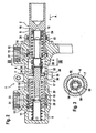
- the master cylinder 1 of Fig. 1 to 5 is arranged by the so-called plunger type with fixed in a housing 7, and on a piston wall 8.9 with a sealing lip 10,11 adjacent sealing collars 12,13 for sealing the pressure chambers 4,5.
- the sealing lips 10,11 can be overflowed in the direction of the wheel brake, if a pressure gradient between not drawn pressure fluid reservoir and wheel brake is set.
- a pressure-compensating connection is also made possible between the two pressure chambers 4, 5, so that there is also a general pressure equalization between the two brake circuits for this unactuated operating state.
- Each of the pistons 2, 3 is assigned a restoring spring 14, 15, which is indirectly supported on the housing 6 with one end 16, 17 on a piston head 18, 19 and with another end via a collar 20, 21 of a sleeve 22, 23.
- the return spring 14,15 is compressed in piston displacement in an actuating direction A, and expanded for the purpose of piston return.
- the pistons 2, 3 have a cup-shaped wall 24, 25, within which the return spring 14, 15 is at least partially arranged.
- the wall 24,25 is centrally penetrated by a central pin 26,27, which ends before its axial exit from the wall 24,25.
- This end 28,29 is provided with a stop 30,31 for the sleeve 22,23, which cooperates with a collar 32,33 such that the sleeve 22,23 is limited relative to the pin 26,27 telescopic.
- the sleeve 22,23 is urged with return spring 14,15 upon actuation in the piston interior.
- the stop 30,31 preferably one, riveted to the pins 26,27 - in particular Taumelvernietete - annular disc.
- the other end of the sleeve 22,23 has the plate-like collar 20,21 to rest the return spring 14,15.
- the second piston 3 additionally has a pin-shaped piston section 34, which is directed counter to the pin 27 and serves as a means for guiding a permanent magnet 35.
- the magnet 35 serves as a signal transmitter for a position transmitter and emits a magnetic field radially in the direction of a sensor element 36 - preferably in the form of a Hall sensor, a magnetoresistive sensor or a reed contact - from which is provided fixedly to the housing 6, and with a not drawn electronic control unit is connected to allow a position detection.
- a Hall sensor or a magnetoresistive sensor as an active component also requires a power supply, while a reed contact as a controlled switch only acts as an opener or closer of a circuit.
- the sensor element 36 may also have local intelligence in the form of a so-called ASIC (Application Specific Integrated Circuit) for better networking within a bus system.
- ASIC Application Specific Integrated Circuit
- the magnet 35 is annular and, as can be seen, disposed between discs 37, 38 of magnetic material on a cylindrical support 39 of non-magnetic material, which has a collar 40 for the axial abutment of the magnet 35.
- the carrier 39 is limitedly displaceable on the pin-shaped piston portion 34 and provided for Verschiebewegbegrenzung of the magnet 35 with an end stop 41, which may be formed as the abutment 30,31 described above. How out Fig.
- the carrier 39 is acted upon by the magnet 35 on the one hand by the restoring spring 14 of the first piston 2 and on the other hand by a further spring means 42 which is supported on the second piston 3, so that the magnet 35 effectively between the pistons 2,3 and is slidably clamped relative to these.
- the spring force of the return spring 14 is greater than the spring force of the other spring means 42. This allows an actuation-related displacement of the magnet 35, even if the second piston 3 is fixed immovably fixed due to a vehicle dynamics control.
- the embodiment according to Fig. 1 has the advantage that the carrier 39 for the magnet 35 - in case of a leak in the region of the second piston 3 (secondary brake circuit) - simultaneously serves to support the first piston 2 (push rod piston) by the carrier 39 after compression of the spring means 42 into abutment reaches the piston 3.
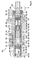
- Fig. 2 is largely consistent with the embodiment Fig. 1 match so that matching features are identified by matching reference numerals, and is omitted a repetition of related parts description. Below, therefore, only the essential differences are discussed.
- the carrier 50 for the magnet 35 is formed as a non-magnetic sleeve, which is part of a cage 51 for the return spring 14.
- the cage 51 has the sleeve, a spring receptacle 52, a push rod 53 and a further sleeve 54.
- the two sleeves (carrier 50, 54) and the push rod 53 are limited by means of mutual stops telescoping and effect according to this embodiment in the unactuated state, a resilient bias of the return spring 14.
- the spring seat 52 is within a recess 55 in the axial direction relative to the sleeve (carrier 50) displaceable, and is supported on a front side of the pin-shaped piston portion 34, whereby the return spring 14 is supported on the pin 34.
- the displacement of the push rod 53 allows expansion of the further spring means which is designed in this embodiment as a cylindrical coil spring. As a result, a displacement of the magnet 35 into the region of the sensor element 36 is made possible.
- a pressure loss (leakage) in the secondary circuit of the piston 3 via the push rod 53 is a central, direct support of the piston 2 (push rod piston) on the piston 3 (secondary piston).
- Fig. 3 illustrates in a cross section in particular the described components sleeve (carrier 50), spring retainer 52, return spring 14 and housing. 6
- a sensor element 36 In order to enable interchangeability and adjustability of a sensor element 36, this is in accordance with a device not claimed 4 and 5 arranged in a receptacle 60 which is fixable in a defined position on the housing 6.
- the sensor element 36 is accommodated as a replaceable structural unit together with rigid conductor elements in a form-fitting manner in the receptacle 60.
- the electrical connection to an electronic control unit of the brake system or another, vehicle-side and networked with the brake control unit is an electrical connection line 61 which is inserted with a plug-in device 62 in the receptacle 60.
- the receptacle 60 can be screwed to a base of the housing 6, wherein defined walls or contact surfaces for the attachment of the receptacle 60 may be provided on the base.
- the receptacle 60 has a housing made of plastic material whose outer wall is provided in the area of contact surfaces socket side with contact tabs which deform when mounting the recording on the housing 6 by firm contact with the contact surfaces such that a play-free attachment of the recording is present.
- the receptacle 60 in the actuating direction of a piston 2,3 and relative to the housing 6 is adjustable and fixable in a defined position.
- the housing 6 has a stop 63 for the receptacle 60, wherein between the stop 63 and receptacle 60 at least one precisely toleranced spacer element 64 are provided to ensure a defined relative position between the sensor element 36 and piston 2.3.
- the receptacle 60 for the position monitoring of a push rod piston (piston 2) can be arranged in a space-saving manner between two pressure medium container connections 65, 66. According to Fig.
- the receptacle 60 is provided at a housing end, which ensures good accessibility of the device.
- a separate bracket 67 between receptacle 60 and sensor element 36 serves as a form-locking securing element against loosening.
- the Fig. 5 illustrates in a schematic plan view of the sensor element with receptacle 60th
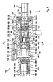
- the master cylinder of Fig. 6 to 19 is configured as a so-called central valve tandem master cylinder 102.
- This has in its basic structure a housing 103 with longitudinal bore 104 for a herein first piston (push rod piston) 105 and a second piston (floating piston) 106.
- a central valve 107,108 is provided per piston 105,106.
- the respective central valve 107,108 interacts to seal an associated pressure chamber 109,110 with the respective piston 105,106, taking into account a predetermined closing path.
- a sealing arrangement 121 arranged in a recess 122 seals the continuation space 115 from the atmosphere.
- the sealing arrangement 121 is delimited on the side facing the pressure chamber 109 by a disk 123, wherein a securing element 125 secures the sealing arrangement 121 as well as the disk 123 in the recess 122.
- the sealing arrangement 121 has a guide ring 126 which consists of a plastic and serves a low-wear guidance of the first piston 105, and a secondary sealing collar 127 arranged on the guide ring 126 in the direction of the first pressure chamber 109.
- the central valves 107, 108 are kept open in an unactuated state by stops 128, 129 formed as cylinder pins, with the stops 128, 129 extending through slot-shaped recesses 130, 131 of the pistons 105, 106.
- the stop 128 is disposed in the longitudinal bore 104, wherein it abuts against the disc 123.
- the stopper 129 is fixed in a housing bore 132 of the housing 103 and the slot-shaped recess 131 of the second piston 106 is disposed in a region between the primary sleeve seal 118 and the secondary boot seal 119.
- Each of the pistons 105,106 is associated with a return spring 133,134, which is supported with a first end 135,136 on a first sleeve 137,138 and with a second end 139,140 on a second sleeve 141 and on a housing bottom 142.
- the first sleeve 137, 138 of the restoring spring 133, 134 is supported on a first piston section 143, 144 of the first and the second piston 105, 106.
- the operation of the central valve tandem master cylinder 102 is basically known.
- the first piston 105 Upon actuation of a brake pedal, not shown, the first piston 105 is moved in the direction of actuation A to the left.
- the associated central valve 107 closes, so that the corresponding pressure chamber 109 is completed with respect to its connection 111 via the follow-up channel 113 and the follow-up space 115 to the expansion tank, not shown.
- the resulting hydrostatic pressure in the pressure chamber 109 of the second piston 106 is moved synchronously with the first piston 105 in the direction of actuation A and closes in the associated brake circuit its central valve 108.
- FIG. 6 which shows the central valve tandem master cylinder 102 in longitudinal section.
- the return spring 133 of the first piston 105 is held in a cage 145, which has the first sleeve 137, the second sleeve 141 and a push rod 146 as constituents.
- the two sleeves 137,141 and the push rod 146 are limited by means of formed on the push rod 146 attacks 148,149 telescopically and cause in the unactuated state, a resilient bias of the return spring 133rd
- the second piston 106 has a second, peg-shaped piston portion 147, whereby the second piston 106 is executed extended in contrast to the known piston and this extension serves as a means for guiding a permanent magnet 150.
- the permanent magnet 150 which in turn serves as a signal transmitter for a position transmitter and a magnetic field radially in the direction of a sensor element 151 - preferably in the form of a Hall sensor, a magnetoresistive sensor or a reed contact - emits, which is provided fixedly to the housing 103 , And with a not shown electronic control unit is connectable to allow a position detection.
- a Hall sensor or a magnetoresistive sensor as an active component also requires a power supply, while a reed contact as a controlled switch only acts as an opener or closer of a circuit.
- the sensor element 151 may also have local intelligence in the form of a so-called ASIC (Application Specific Integrated Circuit) for better networking within a bus system.
- ASIC Application Specific Integrated Circuit
- the magnet 150 is annular and, as can be seen, disposed between discs 152,153 of magnetic material on a cylindrical support 154 of non-magnetic material, which has a collar 155 for the axial abutment of the magnet 150.
- the carrier 154 is limitedly displaceable on the second piston portion 147, which is provided for Verschiebewegbegrenzung of the carrier 154 and thus of the magnet 150 with an end stop 156.
- Fig. 6 shows, the carrier 154 with the magnet 150 on the one hand by means of the second sleeve 141 of the return spring 133 of the first piston 105 and on the other hand by a further spring means 157, which is supported on the second piston 106, applied, so that the magnet 150 in a sense between the piston 105,106 and is slidably clamped relative to these.
- the spring force of the return spring 133 is greater than the spring force of the other spring means 157.
- an actuation-related Displacement of the magnet 150 allows, even if the second piston 106 is immovably fixed due to a vehicle dynamics control, since the movement of the second sleeve 141, which is supported on the collar 155 of the carrier 154, the movement of the magnet 150 and the pole plates 152,153 triggers.
- This embodiment has as the embodiment according to Fig. 1 on the advantage that the carrier 154 for the magnet 150 - at a leak in the region of the second piston 106 (secondary brake circuit) - simultaneously serves to support the first piston 105 by the carrier 154 after compression of the spring means 157 in abutment against the piston 106th arrives.
- the movement and control of the magnet 150 are performed in this embodiment as in the embodiment according to Fig. 1 in series with the movements of the two pistons 105,106.
- Fig. 6 Unlike the embodiment according to Fig. 6 comprises in the embodiment according to the Fig. 7 to 10 the cage 145 in which the return spring 133 of the first piston 105 is held, the first and a second sleeve 137,164, the push rod 146, a non-magnetic, sleeve-shaped support 165 and another spring means 166 whose spring force is smaller than that of the return spring 133rd ,
- Fig. 8 is the clipping X of the Fig. 7 shown enlarged.
- the carrier 165 which can be produced for example from a thin sheet metal material by a forming process, between the stop 148 of the push rod 146 and the second sleeve 164 is arranged. Since the return spring 133 rests with its end 139 on the second sleeve 164, the carrier 165 is held by the bias of the second sleeve 164 by means of the return spring 133 in the direction of actuation A in its abutment against the stop 148.
- the second sleeve 164 is as out Fig. 7 and 8th indicates at the piston portion 147 of the second piston 106 at.
- the carrier 165 which in Fig.
- the permanent magnet 150 and the disc 152 are arranged on the second cylindrical portion 168 of the carrier 165.
- the carrier 165 is guided with its second cylindrical portion 168 on the second piston portion 147 of the second piston 106, wherein inwardly directed, radial projections 169 for guiding and preventing rotation of the carrier 165 in recesses 170 of the second piston portion 147 engage.
- the permanent magnet 150 is thus not directly, but indirectly guided by the carrier 165 on the second piston portion 147 of the second piston 106.
- a radially outwardly directed collar 171 of the second section 168 serves to bear the disc 152 and the magnet 150.
- the further spring means 166 which is arranged in the radial direction between the second sleeve 164 and the carrier 165, abuts with its first end 172 an inner side 174 of the second sleeve 164 and with its second end 173 on the disc 153, whereby the carrier 165, the magnet 150 and the discs 152,153 biased in the in Fig. 7 and 8th shown position are held.
- the second piston 106 is immovably fixed due to a vehicle dynamics control, allows for an actuation-related compression of the return spring 133, the displacement of the push rod 146 in the direction of actuation A expansion of the other spring means 166.
- the carrier 165 with the magnet 150 and the two discs 152,153 thereby moved in the direction of actuation A in the region of the sensor element 151.
- the embodiment according to the Fig. 11 to 14 differs from the embodiment described above according to the Fig. 7 to 10 only in the embodiment of the carrier 165, which is constructed in two parts in the embodiment described below from a spring sleeve 177 and a magnet sleeve 178. Therefore, an overall view of a central valve tandem master cylinder 102 in longitudinal section for this embodiment is omitted.
- Fig. 11 shows a section through the central valve tandem master cylinder 102 along a line AA, which in Fig. 7 the above-described embodiment is indicated.
- the carrier 165 of this embodiment consists of the two components spring sleeve 177 and magnetic sleeve 178, but otherwise as to the Fig. 7 and 8th described on the stop 148 of the push rod 146 abuts and held by the return spring 133 and the biasing force of the return spring to the second sleeve 164 in the position shown. From the FIGS. 13 and 14 , which show the spring sleeve 177 and the magnet sleeve 178, the embodiment is clear.
- the spring sleeve 177 has a cylindrical portion 179 and a circumferential, radially outwardly directed collar 180. From the collar 180, two radial projections 181 emerge, which on the one hand serve to connect to the magnet sleeve 178 and, on the other hand, guide and secure against rotation of the spring sleeve 177 in the recesses 170 of the second piston section 147.
- Fig. 14 illustrates that the magnet sleeve 178 also has a cylindrical portion 182 and a radially outwardly directed collar 183. Further, radially inwardly directed projections 184,185 are provided, which serve on the one hand the connection with the spring sleeve 177 and on the other hand, the guide and anti-rotation of the magnet sleeve 178 in the recesses 170 of the second piston portion 147.
- the projections 184 are provided at an edge 186 of the cylindrical portion 182.
- the projections 185 can be formed, for example, by forming measures of the collar 183.
- the magnet 150 is as out Fig. 12 can be seen, arranged on the cylindrical portion 182 of the magnet sleeve 178 and the disc 152 is due to the bias of the other spring means 166 on the collar 183 of the magnet sleeve 178 at.
- the projections 181 of the spring sleeve 177 are provided in the assembled state of the carrier 165 between the projections 184 and 185 of the magnet sleeve 178. Since the projections 181,184,185 are guided in the recesses 170, the two components 177,178 can not rotate against each other, whereby the connection of the two components 177,178 is ensured.
- the 15 to 19 show a further embodiment of the central valve tandem master cylinder 102.
- the cage 145 in which the return spring 133 of the first piston 105 is held, here comprises the first and a second sleeve 137,187, the push rod 146, a non-magnetic, sleeve-shaped support 188 and another spring means 189 whose spring force is smaller than that of the return spring 133th
- Fig. 15 showing a section of a central valve tandem master cylinder 102
- the magnet 150 and the discs 152, 153 are guided on the second sleeve 187.
- the second sleeve 187 in particular Fig. 17 shows a first and a second cylindrical portion 190,191 and a circumferential collar 192 arranged therebetween.
- the first cylindrical portion 190 is provided with slit-shaped, axial recesses 193, the magnet 150 being guided on the first cylindrical portion 190 and the recesses 193 serving to guide the carrier 188 and the discs 152, 153.
- the carrier 188 is designed similar to the spring sleeve 177 according to Fig. 16 and a cylindrical portion 194 and a circumferential, radially outwardly directed collar 195 has. From the collar 195 radial projections 196 emerge, which serve to guide and anti-rotation of the carrier 188 in the recesses 193 of the second sleeve 187 and the system of the disc 152. For this purpose, the disc 152, which in Fig. 18 is shown, radially inwardly directed projections 197.
- the disc 153 which is in Fig. 19 is shown provided with radial webs 198, which serve the guidance and rotation of the disc 153 in the recesses 193 of the second sleeve 187.
- Fig. 15 shows that the carrier 188 abuts against the stop 148 of the push rod 146 and is arranged between the stop 148 and the second sleeve 187.
- the second sleeve 187 is applied to the second piston portion 147 and the collar 192 of the second sleeve 187 serves to abut the end 139 of the return spring 133 and thus their bias. As a result, the carrier 188 is also held in the position shown.
- the further spring means 189 is held biased between the disc 153 and a, located on an inner side 199 of the second sleeve 187 paragraph 200.
- the second piston 106 is immovably fixed due to a vehicle dynamics control, allows for an actuation-related compression of the return spring 133, the displacement of the push rod 146 in the actuating direction A. Since the second sleeve 187 abuts the second piston 106 and is not moved with the push rod 146, an expansion of the further spring means 189 takes place. The carrier 188 is thus displaced in the direction of actuation A into the region of the sensor element 151 with the magnet 150 and the two disks 152, 154.
- the Fig. 20 serves to explain a brake system 70 with vehicle dynamics control (ESP), in which the invention is particularly applicable.
- the brake system 70 includes a brake device with a pneumatic brake booster 71, the master cylinder 1 or 102 with a pressure medium reservoir 72, wherein pressure chambers of the master cylinder 1,102 are connected via brake lines 73,74 with wheel brakes 75-78.
- the wheel brakes 75-78 are combined in pairs in so-called brake circuits I, II.
- the so-called diagonal distribution has been enforced by combining diagonally opposite wheel brakes of the front and rear axle of a vehicle, in principle, other division such as the so-called black / white division under pairwise combination of the wheel brakes of an axle is possible.
- a pressure sensor 79 serves on the brake pipe 73, which is a pressure chamber with the wheel brakes 75,76 of brake circuit I connects.
- Each brake line 73, 74 has, in series, electromagnetic isolation valves 80, 81 and, for each wheel brake 75, 78, an inlet valve 82, 85 and an outlet valve 86, 89, respectively.
- the two wheel brakes 75, 76, 77, 78 of each brake circuit I, II are connected to a return line 90, 91 in whose line branches per wheel brake 75-78 the outlet valve 86-89 is inserted.
- each return line 90,91 Downstream of the outlet valves 86-89 is located in each return line 90,91 a low pressure accumulator 92,93 which is connected to an input of an electric motor driven pressure medium conveying device 94.95, which feeds the two brake circuits I, II.
- an electric motor driven pressure medium conveying device 94.95 which feeds the two brake circuits I, II.
- a hydraulic connection Between one output of each pressure medium conveying device 94,95 and the associated brake circuit I, II by means of pressure channel 96,97 and a branch 98,99 a hydraulic connection, wherein the pressure increase in the wheel brakes 75-78 via the inlet valves 82-85 is adjustable.
- each pressure medium conveying device 94.95 each a switching valve 100,101 is integrated in the intake branch, which at active vehicle dynamics control is able to establish a pressure medium connection between the master cylinder 1 and the input of the pressure medium conveying devices 94.95.
Landscapes
- Engineering & Computer Science (AREA)
- Transportation (AREA)
- Mechanical Engineering (AREA)
- Physics & Mathematics (AREA)
- Fluid Mechanics (AREA)
- Transmission Of Braking Force In Braking Systems (AREA)
- Arrangement And Mounting Of Devices That Control Transmission Of Motive Force (AREA)
- Valves And Accessory Devices For Braking Systems (AREA)
- Braking Elements And Transmission Devices (AREA)
- Mechanical Control Devices (AREA)
Priority Applications (1)
| Application Number | Priority Date | Filing Date | Title |
|---|---|---|---|
| PL04741453T PL1613519T3 (pl) | 2003-04-07 | 2004-04-07 | Urządzenie do kontroli pozycji i ruchu pedału hamulca |
Applications Claiming Priority (6)
| Application Number | Priority Date | Filing Date | Title |
|---|---|---|---|
| DE10316035 | 2003-04-07 | ||
| DE10322688 | 2003-05-21 | ||
| DE10357709 | 2003-12-09 | ||
| DE102004005405 | 2004-02-03 | ||
| DE102004014808A DE102004014808A1 (de) | 2003-04-07 | 2004-03-24 | Vorrichtung zur Überwachung von Position und Bewegung eines Bremspedals |
| PCT/EP2004/050461 WO2004089714A1 (de) | 2003-04-07 | 2004-04-07 | Vorrichtung zur überwachung von position und bewegung eines bremspedals |
Publications (3)
| Publication Number | Publication Date |
|---|---|
| EP1613519A1 EP1613519A1 (de) | 2006-01-11 |
| EP1613519B1 EP1613519B1 (de) | 2007-08-08 |
| EP1613519B2 true EP1613519B2 (de) | 2010-09-15 |
Family
ID=33163182
Family Applications (1)
| Application Number | Title | Priority Date | Filing Date |
|---|---|---|---|
| EP04741453A Expired - Lifetime EP1613519B2 (de) | 2003-04-07 | 2004-04-07 | Vorrichtung zur überwachung von position und bewegung eines bremspedals |
Country Status (9)
| Country | Link |
|---|---|
| US (1) | US20070182403A1 (pt) |
| EP (1) | EP1613519B2 (pt) |
| KR (1) | KR101085801B1 (pt) |
| AT (1) | ATE369276T1 (pt) |
| BR (1) | BRPI0409218B1 (pt) |
| DE (1) | DE502004004578D1 (pt) |
| MX (1) | MXPA05010405A (pt) |
| PL (1) | PL1613519T3 (pt) |
| WO (1) | WO2004089714A1 (pt) |
Families Citing this family (36)
| Publication number | Priority date | Publication date | Assignee | Title |
|---|---|---|---|---|
| MXPA05010405A (es) | 2003-04-07 | 2005-11-23 | Continental Teves Ag & Co Ohg | Dispositivo para supervisar la posicion y desplazamiento de un pedal de freno. |
| DE102005014414A1 (de) * | 2005-03-24 | 2006-09-28 | Continental Teves Ag & Co. Ohg | Vorrichtung zur Überwachung von Position und Bewegung eines Bremspedals sowie Montageverfahren hierfür |
| KR100711137B1 (ko) * | 2006-03-20 | 2007-04-24 | 포스텍전자주식회사 | 홀 센서를 이용한 브레이크 등 스위치 |
| KR100738147B1 (ko) | 2006-06-28 | 2007-07-10 | 현대자동차주식회사 | 차량용 브레이크 스위치 및 그 제어방법 |
| KR100836403B1 (ko) | 2007-07-06 | 2008-06-09 | 현대자동차주식회사 | 차량의 브레이크 마스터실린더 차단밸브 및 그를 이용한차간거리 제어 해제방법 |
| DE102008018432A1 (de) * | 2008-04-11 | 2009-10-15 | Wabco Gmbh | Positionsmesssystem |
| FR2938810B1 (fr) * | 2008-11-25 | 2010-11-19 | Bosch Gmbh Robert | Maitre-cylindre et procede de montage d'un tel maitre-cylindre |
| DE102009035814A1 (de) | 2009-08-01 | 2011-02-03 | Continental Teves Ag & Co. Ohg | Hauptzylinder insbesondere für eine geregeltes Kraftfahrzeugbremssystem |
| ITMO20090232A1 (it) * | 2009-09-17 | 2011-03-18 | Studio Tecnico 6M Srl | Apparato di comando per valvole di frenatura per macchine operatrici o simili |
| ITMO20100276A1 (it) | 2010-10-04 | 2012-04-05 | Studio Tecnico 6M Srl | Apparato di controllo per veicoli, macchine operatrici o simili |
| KR101277557B1 (ko) | 2011-09-16 | 2013-06-21 | 주식회사 만도 | 브레이크 마스터실린더 |
| KR101888453B1 (ko) * | 2011-10-13 | 2018-08-14 | 현대모비스 주식회사 | 브레이크 장치 |
| KR101315022B1 (ko) * | 2011-11-01 | 2013-10-14 | 주식회사 만도 | 차량용 마스터 실린더 |
| KR101894214B1 (ko) * | 2011-12-13 | 2018-09-03 | 현대모비스 주식회사 | 차량용 마스터실린더 |
| DE102011088350A1 (de) * | 2011-12-13 | 2013-06-13 | Robert Bosch Gmbh | Weckvorrichtung für eine Bremssystemkomponente eines Fahrzeugs und Verfahren zum Wecken mindestens einer Bremssystemkomponente eines Fahrzeugs |
| DE102011088950A1 (de) * | 2011-12-19 | 2013-06-20 | Robert Bosch Gmbh | Differenzwegsensor für ein Bremssystem eines Fahrzeugs und Verfahren zum Ermitteln eines Differenzwegs |
| DE102012212525A1 (de) * | 2012-02-14 | 2013-08-14 | Continental Teves Ag & Co. Ohg | Hauptbremszylinder mit einer Vorrichtung zur berührungslosen Überwachung von Position und Bewegung eines linear bewegbaren Kolbens |
| KR101365024B1 (ko) * | 2012-05-25 | 2014-02-21 | 주식회사 만도 | 브레이크 마스터실린더 |
| KR101966613B1 (ko) * | 2012-09-18 | 2019-04-08 | 현대모비스 주식회사 | 브레이크 램프용 제동장치 |
| DE102012022520A1 (de) * | 2012-11-16 | 2014-05-22 | Lucas Automotive Gmbh | Hauptbremszylinderanordnung mit Betätigungserfassung für eine Kraftfahrzeugbremsanlage |
| DE102012022519A1 (de) * | 2012-11-16 | 2014-05-22 | Lucas Automotive Gmbh | Hauptbremszylinderanordnung mit Betätigungserfassung für eine Kraftfahrzeugbremsanlage |
| CN103115093B (zh) * | 2013-01-25 | 2015-09-23 | 重庆市喜植机械设备有限公司 | 磁压式比例分配式制动主缸 |
| KR101702844B1 (ko) | 2014-02-27 | 2017-02-06 | 주식회사 만도 | 브레이크 마스터 실린더 |
| KR101971266B1 (ko) | 2014-04-30 | 2019-04-22 | 주식회사 만도 | 브레이크 마스터실린더 |
| FR3020660B1 (fr) * | 2014-05-05 | 2017-01-27 | Valeo Embrayages | Dispositif de commande hydraulique, son procede de fabrication et systeme de commande d'embrayage ou de freinage comprenant ledit dispositif |
| KR101560622B1 (ko) | 2014-05-14 | 2015-10-15 | 주식회사 만도 | 마스터실린더 |
| JP6375542B2 (ja) * | 2014-07-15 | 2018-08-22 | 日立オートモティブシステムズ株式会社 | ブレーキ装置及びマスタシリンダ |
| KR101594318B1 (ko) | 2014-10-13 | 2016-02-16 | 주식회사 만도 | 브레이크 마스터 실린더 |
| KR102345500B1 (ko) | 2015-05-06 | 2022-01-03 | 주식회사 만도 | 브레이크 마스터 실린더 |
| KR101657567B1 (ko) | 2015-05-18 | 2016-09-19 | 주식회사 만도 | 마스터 실린더용 bls 모듈 |
| US10780865B2 (en) * | 2015-05-29 | 2020-09-22 | Hitachi Automotive Systems, Ltd. | Electric booster and stroke detector |
| KR20180022725A (ko) * | 2015-06-30 | 2018-03-06 | 콘티넨탈 테베스 아게 운트 코. 오하게 | 모터 차량 브레이크 시스템을 위한 브레이크 압력을 생성하기 위한 유압 유닛 |
| DE202019004415U1 (de) * | 2019-10-28 | 2019-11-06 | K.W.H. Ciclosport Vertriebs GmbH | Sensorvorrichtung |
| US20250214556A1 (en) * | 2022-03-31 | 2025-07-03 | Zf Cv Systems Europe Bv | Brake valve with a magnet holder for a position sensor |
| IT202300011307A1 (it) * | 2023-06-05 | 2024-12-05 | Brembo Spa | Disposizione di magnete lineare per impianti frenanti elettronicamente assistiti |
| CN116811828A (zh) * | 2023-07-19 | 2023-09-29 | 联创汽车电子有限公司 | 位移传感器结构 |
Citations (1)
| Publication number | Priority date | Publication date | Assignee | Title |
|---|---|---|---|---|
| EP0480608B1 (en) † | 1990-10-10 | 1995-07-05 | Ford Motor Company Limited | Brake pedal travel warning system |
Family Cites Families (5)
| Publication number | Priority date | Publication date | Assignee | Title |
|---|---|---|---|---|
| DE10053995A1 (de) * | 2000-10-31 | 2002-05-08 | Continental Teves Ag & Co Ohg | In einen Hauptzylinder integrierter Signalgeber mit Hall-Sensor |
| DE10059128A1 (de) * | 2000-11-29 | 2002-06-13 | Lucas Varity Gmbh | Vorrichtung zur Ermittlung von Positionen und Bewegungen eines Bremspedales für eine Fahrzeugbremsanlage |
| US6619039B2 (en) * | 2001-04-25 | 2003-09-16 | Delphi Technologies, Inc. | Brake master cylinder-sensor system and method |
| AUPR665501A0 (en) * | 2001-07-27 | 2001-08-16 | Joseph, Oscar Matthew | Master brake cylinder with opposing pistons |
| MXPA05010405A (es) | 2003-04-07 | 2005-11-23 | Continental Teves Ag & Co Ohg | Dispositivo para supervisar la posicion y desplazamiento de un pedal de freno. |
-
2004
- 2004-04-07 MX MXPA05010405A patent/MXPA05010405A/es active IP Right Grant
- 2004-04-07 DE DE502004004578T patent/DE502004004578D1/de not_active Expired - Lifetime
- 2004-04-07 EP EP04741453A patent/EP1613519B2/de not_active Expired - Lifetime
- 2004-04-07 US US10/552,407 patent/US20070182403A1/en not_active Abandoned
- 2004-04-07 WO PCT/EP2004/050461 patent/WO2004089714A1/de not_active Ceased
- 2004-04-07 KR KR1020057019185A patent/KR101085801B1/ko not_active Expired - Lifetime
- 2004-04-07 AT AT04741453T patent/ATE369276T1/de not_active IP Right Cessation
- 2004-04-07 BR BRPI0409218-0A patent/BRPI0409218B1/pt not_active IP Right Cessation
- 2004-04-07 PL PL04741453T patent/PL1613519T3/pl unknown
Patent Citations (1)
| Publication number | Priority date | Publication date | Assignee | Title |
|---|---|---|---|---|
| EP0480608B1 (en) † | 1990-10-10 | 1995-07-05 | Ford Motor Company Limited | Brake pedal travel warning system |
Also Published As
| Publication number | Publication date |
|---|---|
| BRPI0409218B1 (pt) | 2013-02-19 |
| MXPA05010405A (es) | 2005-11-23 |
| WO2004089714A1 (de) | 2004-10-21 |
| EP1613519A1 (de) | 2006-01-11 |
| ATE369276T1 (de) | 2007-08-15 |
| EP1613519B1 (de) | 2007-08-08 |
| KR101085801B1 (ko) | 2011-11-22 |
| PL1613519T3 (pl) | 2007-12-31 |
| BRPI0409218A (pt) | 2006-03-28 |
| US20070182403A1 (en) | 2007-08-09 |
| KR20060006916A (ko) | 2006-01-20 |
| DE502004004578D1 (de) | 2007-09-20 |
Similar Documents
| Publication | Publication Date | Title |
|---|---|---|
| EP1613519B2 (de) | Vorrichtung zur überwachung von position und bewegung eines bremspedals | |
| EP0633850B1 (de) | Pneumatischer kraftverstärker mit elektromagnetischer hilfssteuerung, insbesondere für kraftfahrzeug-bremsanlagen | |
| DE4405092C1 (de) | Pneumatischer Kraftverstärker mit elektromagnetischer Hilfssteuerung, insbesondere für Kraftfahrzeug-Bremsanlagen | |
| DE102004058875A1 (de) | Verfahren und Vorrichtung zur Regelung eines Kraftfahrzeuges mit einer elektrohydraulischen Bremsanlage mit Fahrdynamikregelung | |
| DE102012203099A1 (de) | Pedalwegsimulator, Betätigungseinheit für eine hydraulische Bremsanlage sowie Bremsanlage | |
| DE102014225962A1 (de) | Bremsanlage für Kraftfahrzeuge | |
| DE102004014808A1 (de) | Vorrichtung zur Überwachung von Position und Bewegung eines Bremspedals | |
| DE102010062163A1 (de) | Vorrichtung zur Überwachung von Position und Bewegung eines Bremspedals | |
| DE4405076A1 (de) | Pneumatischer Kraftverstärker mit elektromagnetischer Hilfssteuerung, insbesondere für Kraftfahrzeug-Bremsanlagen | |
| DE102011112515A1 (de) | Betätigungsvorrichtung für eine Kraftfahrzeug-Bremsanlage | |
| EP3526087B1 (de) | Magnetventil und hydraulisches bremssystem für ein fahrzeug | |
| DE102016219939A1 (de) | Magnetventil und hydraulisches Bremssystem für ein Fahrzeug | |
| DE102017200420A1 (de) | Verfahren zum Betreiben einer Bremsanlage und Bremsanlage | |
| EP2427355B1 (de) | Bremsbetätigungseinheit zur betätigung einer kraftfahrzeugbremsanlage | |
| DE102008003454A1 (de) | Hydraulikfluidpumpe mit einem Dichtelement | |
| DE4435623A1 (de) | Bremsdruckmodulationseinrichtung | |
| DE102015006396A1 (de) | Elektrohydraulische Bremskrafterzeugungsvorrichtung für eine elektrohydraulische Kraftfahrzeug-Bremsanlage | |
| EP1863690A1 (de) | Elektrohydraulische bremsanlage mit fahrdynamikregelung | |
| DE69301604T2 (de) | Steuerventil für einen unterdruck-kraftverstärker | |
| DE102012222547A1 (de) | Vorrichtung zur Überwachung von Position und Bewegung eines Kolbens | |
| DE102010002848A1 (de) | Bremsbetätigungseinheit zur Betätigung einer Kraftfahrzeugbremsanlage vom Typ "Brake-by-wire" | |
| EP1694545B1 (de) | Verfahren und vorrichtung zur regelung eines kraftfahrzeuges mit einer elektrisch geregelten bremsanlage mit fahrdynamikregelung | |
| WO2006100215A1 (de) | Vorrichtung zur überwachung von position und bewegung eines bremspedals sowie montageverfahren hierfür | |
| EP3268253B1 (de) | Hydraulische bremsanlage | |
| DE102010002651A1 (de) | Pneumatischer Bremskraftverstärker für eine Kraftfahrzeugbremsanlage |
Legal Events
| Date | Code | Title | Description |
|---|---|---|---|
| PUAI | Public reference made under article 153(3) epc to a published international application that has entered the european phase |
Free format text: ORIGINAL CODE: 0009012 |
|
| 17P | Request for examination filed |
Effective date: 20051107 |
|
| AK | Designated contracting states |
Kind code of ref document: A1 Designated state(s): AT BE BG CH CY CZ DE DK EE ES FI FR GB GR HU IE IT LI LU MC NL PL PT RO SE SI SK TR |
|
| AX | Request for extension of the european patent |
Extension state: AL HR LT LV MK |
|
| DAX | Request for extension of the european patent (deleted) | ||
| 17Q | First examination report despatched |
Effective date: 20060622 |
|
| GRAP | Despatch of communication of intention to grant a patent |
Free format text: ORIGINAL CODE: EPIDOSNIGR1 |
|
| GRAS | Grant fee paid |
Free format text: ORIGINAL CODE: EPIDOSNIGR3 |
|
| GRAA | (expected) grant |
Free format text: ORIGINAL CODE: 0009210 |
|
| AK | Designated contracting states |
Kind code of ref document: B1 Designated state(s): AT BE BG CH CY CZ DE DK EE ES FI FR GB GR HU IE IT LI LU MC NL PL PT RO SE SI SK TR |
|
| REG | Reference to a national code |
Ref country code: GB Ref legal event code: FG4D Free format text: NOT ENGLISH |
|
| REG | Reference to a national code |
Ref country code: CH Ref legal event code: EP |
|
| REG | Reference to a national code |
Ref country code: IE Ref legal event code: FG4D Free format text: LANGUAGE OF EP DOCUMENT: GERMAN |
|
| REF | Corresponds to: |
Ref document number: 502004004578 Country of ref document: DE Date of ref document: 20070920 Kind code of ref document: P |
|
| GBT | Gb: translation of ep patent filed (gb section 77(6)(a)/1977) |
Effective date: 20070919 |
|
| REG | Reference to a national code |
Ref country code: PL Ref legal event code: T3 |
|
| PG25 | Lapsed in a contracting state [announced via postgrant information from national office to epo] |
Ref country code: BG Free format text: LAPSE BECAUSE OF FAILURE TO SUBMIT A TRANSLATION OF THE DESCRIPTION OR TO PAY THE FEE WITHIN THE PRESCRIBED TIME-LIMIT Effective date: 20071108 Ref country code: NL Free format text: LAPSE BECAUSE OF FAILURE TO SUBMIT A TRANSLATION OF THE DESCRIPTION OR TO PAY THE FEE WITHIN THE PRESCRIBED TIME-LIMIT Effective date: 20070808 Ref country code: FI Free format text: LAPSE BECAUSE OF FAILURE TO SUBMIT A TRANSLATION OF THE DESCRIPTION OR TO PAY THE FEE WITHIN THE PRESCRIBED TIME-LIMIT Effective date: 20070808 |
|
| NLV1 | Nl: lapsed or annulled due to failure to fulfill the requirements of art. 29p and 29m of the patents act | ||
| REG | Reference to a national code |
Ref country code: ES Ref legal event code: FG2A Ref document number: 2289531 Country of ref document: ES Kind code of ref document: T3 |
|
| ET | Fr: translation filed | ||
| REG | Reference to a national code |
Ref country code: IE Ref legal event code: FD4D |
|
| PG25 | Lapsed in a contracting state [announced via postgrant information from national office to epo] |
Ref country code: GR Free format text: LAPSE BECAUSE OF FAILURE TO SUBMIT A TRANSLATION OF THE DESCRIPTION OR TO PAY THE FEE WITHIN THE PRESCRIBED TIME-LIMIT Effective date: 20071109 Ref country code: DK Free format text: LAPSE BECAUSE OF FAILURE TO SUBMIT A TRANSLATION OF THE DESCRIPTION OR TO PAY THE FEE WITHIN THE PRESCRIBED TIME-LIMIT Effective date: 20070808 |
|
| PLBI | Opposition filed |
Free format text: ORIGINAL CODE: 0009260 |
|
| PG25 | Lapsed in a contracting state [announced via postgrant information from national office to epo] |
Ref country code: SK Free format text: LAPSE BECAUSE OF FAILURE TO SUBMIT A TRANSLATION OF THE DESCRIPTION OR TO PAY THE FEE WITHIN THE PRESCRIBED TIME-LIMIT Effective date: 20070808 Ref country code: IE Free format text: LAPSE BECAUSE OF FAILURE TO SUBMIT A TRANSLATION OF THE DESCRIPTION OR TO PAY THE FEE WITHIN THE PRESCRIBED TIME-LIMIT Effective date: 20070808 Ref country code: PT Free format text: LAPSE BECAUSE OF FAILURE TO SUBMIT A TRANSLATION OF THE DESCRIPTION OR TO PAY THE FEE WITHIN THE PRESCRIBED TIME-LIMIT Effective date: 20080108 |
|
| PLAX | Notice of opposition and request to file observation + time limit sent |
Free format text: ORIGINAL CODE: EPIDOSNOBS2 |
|
| 26 | Opposition filed |
Opponent name: FTE AUTOMOTIVE GMBH Effective date: 20080508 |
|
| PG25 | Lapsed in a contracting state [announced via postgrant information from national office to epo] |
Ref country code: SE Free format text: LAPSE BECAUSE OF FAILURE TO SUBMIT A TRANSLATION OF THE DESCRIPTION OR TO PAY THE FEE WITHIN THE PRESCRIBED TIME-LIMIT Effective date: 20071108 Ref country code: RO Free format text: LAPSE BECAUSE OF FAILURE TO SUBMIT A TRANSLATION OF THE DESCRIPTION OR TO PAY THE FEE WITHIN THE PRESCRIBED TIME-LIMIT Effective date: 20070808 |
|
| PLAF | Information modified related to communication of a notice of opposition and request to file observations + time limit |
Free format text: ORIGINAL CODE: EPIDOSCOBS2 |
|
| BERE | Be: lapsed |
Owner name: CONTINENTAL TEVES A.G. & CO. OHG Effective date: 20080430 |
|
| PG25 | Lapsed in a contracting state [announced via postgrant information from national office to epo] |
Ref country code: MC Free format text: LAPSE BECAUSE OF NON-PAYMENT OF DUE FEES Effective date: 20080430 |
|
| REG | Reference to a national code |
Ref country code: CH Ref legal event code: PL |
|
| PLBB | Reply of patent proprietor to notice(s) of opposition received |
Free format text: ORIGINAL CODE: EPIDOSNOBS3 |
|
| PG25 | Lapsed in a contracting state [announced via postgrant information from national office to epo] |
Ref country code: LI Free format text: LAPSE BECAUSE OF NON-PAYMENT OF DUE FEES Effective date: 20080430 Ref country code: CH Free format text: LAPSE BECAUSE OF NON-PAYMENT OF DUE FEES Effective date: 20080430 Ref country code: EE Free format text: LAPSE BECAUSE OF FAILURE TO SUBMIT A TRANSLATION OF THE DESCRIPTION OR TO PAY THE FEE WITHIN THE PRESCRIBED TIME-LIMIT Effective date: 20070808 |
|
| PG25 | Lapsed in a contracting state [announced via postgrant information from national office to epo] |
Ref country code: BE Free format text: LAPSE BECAUSE OF NON-PAYMENT OF DUE FEES Effective date: 20080430 |
|
| PG25 | Lapsed in a contracting state [announced via postgrant information from national office to epo] |
Ref country code: CZ Free format text: LAPSE BECAUSE OF NON-PAYMENT OF DUE FEES Effective date: 20080407 |
|
| PG25 | Lapsed in a contracting state [announced via postgrant information from national office to epo] |
Ref country code: SI Free format text: LAPSE BECAUSE OF FAILURE TO SUBMIT A TRANSLATION OF THE DESCRIPTION OR TO PAY THE FEE WITHIN THE PRESCRIBED TIME-LIMIT Effective date: 20070808 |
|
| PG25 | Lapsed in a contracting state [announced via postgrant information from national office to epo] |
Ref country code: CY Free format text: LAPSE BECAUSE OF FAILURE TO SUBMIT A TRANSLATION OF THE DESCRIPTION OR TO PAY THE FEE WITHIN THE PRESCRIBED TIME-LIMIT Effective date: 20070808 |
|
| PG25 | Lapsed in a contracting state [announced via postgrant information from national office to epo] |
Ref country code: AT Free format text: LAPSE BECAUSE OF NON-PAYMENT OF DUE FEES Effective date: 20080407 |
|
| APBM | Appeal reference recorded |
Free format text: ORIGINAL CODE: EPIDOSNREFNO |
|
| APBP | Date of receipt of notice of appeal recorded |
Free format text: ORIGINAL CODE: EPIDOSNNOA2O |
|
| APAH | Appeal reference modified |
Free format text: ORIGINAL CODE: EPIDOSCREFNO |
|
| APBU | Appeal procedure closed |
Free format text: ORIGINAL CODE: EPIDOSNNOA9O |
|
| PG25 | Lapsed in a contracting state [announced via postgrant information from national office to epo] |
Ref country code: LU Free format text: LAPSE BECAUSE OF NON-PAYMENT OF DUE FEES Effective date: 20080407 Ref country code: HU Free format text: LAPSE BECAUSE OF FAILURE TO SUBMIT A TRANSLATION OF THE DESCRIPTION OR TO PAY THE FEE WITHIN THE PRESCRIBED TIME-LIMIT Effective date: 20080209 |
|
| PUAH | Patent maintained in amended form |
Free format text: ORIGINAL CODE: 0009272 |
|
| STAA | Information on the status of an ep patent application or granted ep patent |
Free format text: STATUS: PATENT MAINTAINED AS AMENDED |
|
| PG25 | Lapsed in a contracting state [announced via postgrant information from national office to epo] |
Ref country code: TR Free format text: LAPSE BECAUSE OF FAILURE TO SUBMIT A TRANSLATION OF THE DESCRIPTION OR TO PAY THE FEE WITHIN THE PRESCRIBED TIME-LIMIT Effective date: 20070808 |
|
| PGFP | Annual fee paid to national office [announced via postgrant information from national office to epo] |
Ref country code: PL Payment date: 20100323 Year of fee payment: 7 |
|
| 27A | Patent maintained in amended form |
Effective date: 20100915 |
|
| AK | Designated contracting states |
Kind code of ref document: B2 Designated state(s): AT BE BG CH CY CZ DE DK EE ES FI FR GB GR HU IE IT LI LU MC NL PL PT RO SE SI SK TR |
|
| REG | Reference to a national code |
Ref country code: ES Ref legal event code: DC2A Effective date: 20110214 |
|
| PG25 | Lapsed in a contracting state [announced via postgrant information from national office to epo] |
Ref country code: PL Free format text: LAPSE BECAUSE OF FAILURE TO SUBMIT A TRANSLATION OF THE DESCRIPTION OR TO PAY THE FEE WITHIN THE PRESCRIBED TIME-LIMIT Effective date: 20070808 |
|
| PG25 | Lapsed in a contracting state [announced via postgrant information from national office to epo] |
Ref country code: PL Free format text: LAPSE BECAUSE OF FAILURE TO SUBMIT A TRANSLATION OF THE DESCRIPTION OR TO PAY THE FEE WITHIN THE PRESCRIBED TIME-LIMIT Effective date: 20100915 |
|
| PGFP | Annual fee paid to national office [announced via postgrant information from national office to epo] |
Ref country code: GB Payment date: 20130423 Year of fee payment: 10 |
|
| PGFP | Annual fee paid to national office [announced via postgrant information from national office to epo] |
Ref country code: IT Payment date: 20130419 Year of fee payment: 10 |
|
| GBPC | Gb: european patent ceased through non-payment of renewal fee |
Effective date: 20140407 |
|
| PG25 | Lapsed in a contracting state [announced via postgrant information from national office to epo] |
Ref country code: GB Free format text: LAPSE BECAUSE OF NON-PAYMENT OF DUE FEES Effective date: 20140407 |
|
| PG25 | Lapsed in a contracting state [announced via postgrant information from national office to epo] |
Ref country code: IT Free format text: LAPSE BECAUSE OF NON-PAYMENT OF DUE FEES Effective date: 20140407 |
|
| REG | Reference to a national code |
Ref country code: FR Ref legal event code: PLFP Year of fee payment: 13 |
|
| REG | Reference to a national code |
Ref country code: FR Ref legal event code: PLFP Year of fee payment: 14 |
|
| REG | Reference to a national code |
Ref country code: FR Ref legal event code: PLFP Year of fee payment: 15 |
|
| REG | Reference to a national code |
Ref country code: DE Ref legal event code: R084 Ref document number: 502004004578 Country of ref document: DE |
|
| REG | Reference to a national code |
Ref country code: DE Ref legal event code: R081 Ref document number: 502004004578 Country of ref document: DE Owner name: CONTINENTAL AUTOMOTIVE TECHNOLOGIES GMBH, DE Free format text: FORMER OWNER: CONTINENTAL TEVES AG & CO. OHG, 60488 FRANKFURT, DE |
|
| PGFP | Annual fee paid to national office [announced via postgrant information from national office to epo] |
Ref country code: FR Payment date: 20230420 Year of fee payment: 20 Ref country code: ES Payment date: 20230627 Year of fee payment: 20 Ref country code: DE Payment date: 20230430 Year of fee payment: 20 |
|
| REG | Reference to a national code |
Ref country code: DE Ref legal event code: R071 Ref document number: 502004004578 Country of ref document: DE |
|
| PG25 | Lapsed in a contracting state [announced via postgrant information from national office to epo] |
Ref country code: ES Free format text: LAPSE BECAUSE OF EXPIRATION OF PROTECTION Effective date: 20240408 |
|
| REG | Reference to a national code |
Ref country code: ES Ref legal event code: FD2A Effective date: 20240426 |
|
| PG25 | Lapsed in a contracting state [announced via postgrant information from national office to epo] |
Ref country code: ES Free format text: LAPSE BECAUSE OF EXPIRATION OF PROTECTION Effective date: 20240408 |