EP1619419A1 - Transmission case cover for all terrain vehicle - Google Patents
Transmission case cover for all terrain vehicle Download PDFInfo
- Publication number
- EP1619419A1 EP1619419A1 EP04016960A EP04016960A EP1619419A1 EP 1619419 A1 EP1619419 A1 EP 1619419A1 EP 04016960 A EP04016960 A EP 04016960A EP 04016960 A EP04016960 A EP 04016960A EP 1619419 A1 EP1619419 A1 EP 1619419A1
- Authority
- EP
- European Patent Office
- Prior art keywords
- transmission case
- case cover
- continuously variable
- holder
- engine
- Prior art date
- Legal status (The legal status is an assumption and is not a legal conclusion. Google has not performed a legal analysis and makes no representation as to the accuracy of the status listed.)
- Granted
Links
- 230000005540 biological transmission Effects 0.000 title claims abstract description 50
- 230000007246 mechanism Effects 0.000 claims abstract description 14
- 239000007858 starting material Substances 0.000 claims description 7
- 239000003570 air Substances 0.000 description 7
- 230000004308 accommodation Effects 0.000 description 1
- 230000006978 adaptation Effects 0.000 description 1
- 239000012080 ambient air Substances 0.000 description 1
- 238000002485 combustion reaction Methods 0.000 description 1
- 238000001816 cooling Methods 0.000 description 1
- 230000003247 decreasing effect Effects 0.000 description 1
- 238000004880 explosion Methods 0.000 description 1
- 238000004519 manufacturing process Methods 0.000 description 1
- 238000000034 method Methods 0.000 description 1
- 230000004048 modification Effects 0.000 description 1
- 238000012986 modification Methods 0.000 description 1
- 230000009467 reduction Effects 0.000 description 1
- 238000006467 substitution reaction Methods 0.000 description 1
Images


Classifications
-
- F—MECHANICAL ENGINEERING; LIGHTING; HEATING; WEAPONS; BLASTING
- F16—ENGINEERING ELEMENTS AND UNITS; GENERAL MEASURES FOR PRODUCING AND MAINTAINING EFFECTIVE FUNCTIONING OF MACHINES OR INSTALLATIONS; THERMAL INSULATION IN GENERAL
- F16H—GEARING
- F16H57/00—General details of gearing
- F16H57/02—Gearboxes; Mounting gearing therein
- F16H57/031—Gearboxes; Mounting gearing therein characterised by covers or lids for gearboxes
-
- F—MECHANICAL ENGINEERING; LIGHTING; HEATING; WEAPONS; BLASTING
- F16—ENGINEERING ELEMENTS AND UNITS; GENERAL MEASURES FOR PRODUCING AND MAINTAINING EFFECTIVE FUNCTIONING OF MACHINES OR INSTALLATIONS; THERMAL INSULATION IN GENERAL
- F16H—GEARING
- F16H57/00—General details of gearing
- F16H57/02—Gearboxes; Mounting gearing therein
- F16H57/035—Gearboxes for gearing with endless flexible members
-
- F—MECHANICAL ENGINEERING; LIGHTING; HEATING; WEAPONS; BLASTING
- F16—ENGINEERING ELEMENTS AND UNITS; GENERAL MEASURES FOR PRODUCING AND MAINTAINING EFFECTIVE FUNCTIONING OF MACHINES OR INSTALLATIONS; THERMAL INSULATION IN GENERAL
- F16H—GEARING
- F16H57/00—General details of gearing
- F16H57/04—Features relating to lubrication or cooling or heating
- F16H57/0412—Cooling or heating; Control of temperature
- F16H57/0415—Air cooling or ventilation; Heat exchangers; Thermal insulations
-
- F—MECHANICAL ENGINEERING; LIGHTING; HEATING; WEAPONS; BLASTING
- F16—ENGINEERING ELEMENTS AND UNITS; GENERAL MEASURES FOR PRODUCING AND MAINTAINING EFFECTIVE FUNCTIONING OF MACHINES OR INSTALLATIONS; THERMAL INSULATION IN GENERAL
- F16H—GEARING
- F16H57/00—General details of gearing
- F16H57/02—Gearboxes; Mounting gearing therein
- F16H2057/0203—Gearboxes; Mounting gearing therein the gearbox is associated or combined with a crank case of an engine
-
- F—MECHANICAL ENGINEERING; LIGHTING; HEATING; WEAPONS; BLASTING
- F16—ENGINEERING ELEMENTS AND UNITS; GENERAL MEASURES FOR PRODUCING AND MAINTAINING EFFECTIVE FUNCTIONING OF MACHINES OR INSTALLATIONS; THERMAL INSULATION IN GENERAL
- F16H—GEARING
- F16H57/00—General details of gearing
- F16H57/02—Gearboxes; Mounting gearing therein
- F16H2057/02039—Gearboxes for particular applications
- F16H2057/02043—Gearboxes for particular applications for vehicle transmissions
- F16H2057/02065—Gearboxes for particular applications for vehicle transmissions for motorcycles or squads
Definitions
- the present invention is related to a transmission case cover for all terrain vehicles, and more particularly, to one that provides additional functions without compromising the existing functions of the transmission case.
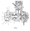
- a continuously variable transmission mechanism 2 is accommodated in a transmission case 11, and the power generated by an engine 12 is transmitted through a crankshaft 13 in a crankshaft case 16 for the continuously variable transmission mechanism 2 to drive.
- the continuously variable transmission mechanism 2 includes a pulley disk 21 disposed on the crankshaft 13, a driving disk 22 provided on the crankshaft 13 at where on one side of the pulley disk 21, a slanting board 23 provided on the crankshaft 13 at where on the other side of the pulley disk 21, a ball 24 provided and restricted between the pulley disk 21 and the slanting board 23, a passive shaft 25 to drive rear wheels, two passive disks 26 provided on the passive shaft 25, a clutch 27 fixed to the passive shaft 25, a transmission belt 28, and a bearing 29 provided on a cover 111 of the transmission case 11 to support the passive shaft 25.
- the pulley disk 21 and the driving disk 22 define an active disk of the continuously variable transmission mechanism.
- One end of the transmission belt 28 is located at where between the driving disk 22 and the pulley disk 21 while the other end of the transmission belt 28 falls between two passive disks 26.
- an air guide port 112 will be provided in front of the transmission case cover 111 to introduce in the fresh air from the ambient for cooling down the continuously variable transmission mechanism 2.
- the air guide port 112 is made integrated with the transmission case cover 111, and the air introduced from the ambient enters from an inlet 114 through a passage 113 into the transmission case 11 to cool the continuously variable transmission mechanism 2.
- the structure of the transmission case cover 111 of the prior art has been used in the trade for a long time. However, it only functions to screen the continuously variable transmission mechanism 2 and to introduce in the fresh air from the ambient. To a modem enterprise that seeks after higher universality and lower production cost, it is justified to develop the transmission case cover that can be effectively upgraded with its common functions to lower its cost and increase its universality without compromising the existing functions.
- the primary purpose of the present invention is to provide a transmission case cover for all terrain vehicles to reduce its cost and promote its universality without compromising the efficacy of the continuously variable transmission.
- a holder is provided to the transmission case cover of a continuously variable transmission mechanism, an opening is disposed in the space encompassed by the holder facing the crankshaft, and the space covered by a mobile cover contains also an manual starter for effective increasing the common functions of the transmission cover.
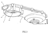
- a preferred embodiment of the present invention is provided with a cover holder 4 on the outer side of a transmission case 3 at where closer to a port 31 to define a space 41 encompassed by the case holder 4.
- an opening 42 is provided on the crankshaft 5, and the space 41 is enclosed with a cap 6, which can be mounted or removed through a screw 61 as desired without affecting the admittance of the ambient air into the transmission case through the port, a passage 32 and an inlet 32.
- the holder 4 is provided on one side of the transmission case cover 3 and the cap 6 is used to close up the space 41 encompassed by the holder 4 so to accommodate any member that provides additional function.
- a pull starter 7 of the prior art is disposed inside the cap 6. With a cord 71 adapted to the starter 7 pulled to drive a drum 72, and further a starter gear 73, the crankshaft 5 rotates synchronously to start the engine. Meanwhile, the fresh air introduced from the ambient through the port 31 is not affected by the presence of the pull starter 7 provided in the cap 6. The fresh air remains passing through the port 31 into the passage 32, and the inlet to enter into the transmission case to cool the continuously variable transmission mechanism. Without affecting the existing function of the transmission case and the continuously variable transmission mechanism, the adaptation of the holder 4 and the opening 42 in conjunction with the enclosure by the cap 6 allows an additional space for the accommodation of a manual pull starter 7 to start the engine.
- the present invention by providing the holder 4, the opening 42 and the cap 6 allows the transmission case applicable to the model of the automobile with or without the manual pull start of the engine at the same time to share the same transmission case cover 3 for cost reduction and increased universality of the transmission case cover 3.
Landscapes
- Engineering & Computer Science (AREA)
- General Engineering & Computer Science (AREA)
- Mechanical Engineering (AREA)
- General Details Of Gearings (AREA)
Abstract
Description
- The present invention is related to a transmission case cover for all terrain vehicles, and more particularly, to one that provides additional functions without compromising the existing functions of the transmission case.
- Referring to Fig. 1 of the accompanying drawings, a continuously
variable transmission mechanism 2 is accommodated in atransmission case 11, and the power generated by anengine 12 is transmitted through acrankshaft 13 in acrankshaft case 16 for the continuouslyvariable transmission mechanism 2 to drive. The continuouslyvariable transmission mechanism 2 includes a pulley disk 21 disposed on thecrankshaft 13, adriving disk 22 provided on thecrankshaft 13 at where on one side of the pulley disk 21, aslanting board 23 provided on thecrankshaft 13 at where on the other side of the pulley disk 21, aball 24 provided and restricted between the pulley disk 21 and theslanting board 23, apassive shaft 25 to drive rear wheels, twopassive disks 26 provided on thepassive shaft 25, aclutch 27 fixed to thepassive shaft 25, atransmission belt 28, and abearing 29 provided on acover 111 of thetransmission case 11 to support thepassive shaft 25. Wherein, the pulley disk 21 and thedriving disk 22 define an active disk of the continuously variable transmission mechanism. One end of thetransmission belt 28 is located at where between thedriving disk 22 and the pulley disk 21 while the other end of thetransmission belt 28 falls between twopassive disks 26. - Power generated from the explosion in the combustion chamber of the
engine 12 pushes apiston 14 to engage in reciprocal movement to drive thecrankshaft 13 to rotate, and both of the pulley disk 21 and thedriving disk 22 rotate synchronously; meanwhile, theball 24 travels when subject to eccentric force. As a throttle opens wider, the rpm of thecrankshaft 13 increases to subject theball 24 to higher eccentric force; theball 24 starts to travel outwardly to hold against the pulley disk 21; in turn, the pulley disk 21 moves toward thedriving disk 22 to narrow down the distance between thedriving disk 22 and the pulley disk 21, forcing thetransmission belt 28 to expand for increasing the coverage of the revolving circumference of thetransmission belt 28 and further to increase the rpm of bothpassive disks 26. Thepassive shaft 25 is then driven through theclutch 27 to drive the rear wheels (not illustrated). Consequently, the drive speed of the automobile is increased. - However, when the throttle is released, the eccentric force applied on the
ball 24 is reduced, and the distance between thedriving disk 22 and the pulley disk 21 gets larger in conjunction with the squeeze from thetransmission belt 28 to reduce its coverage of the circumferential revolution. The drive speed of the automobile is decreased since the rpm of bothpassive disks 26 is slowed down and that transmitted to the rear wheels is also slowed down due to the reduced rpm of thepassive shaft 25. - Generally, to maintain the normal operation of the continuously
variable transmission mechanism 2, anair guide port 112 will be provided in front of thetransmission case cover 111 to introduce in the fresh air from the ambient for cooling down the continuouslyvariable transmission mechanism 2. Theair guide port 112 is made integrated with thetransmission case cover 111, and the air introduced from the ambient enters from aninlet 114 through apassage 113 into thetransmission case 11 to cool the continuouslyvariable transmission mechanism 2. The structure of thetransmission case cover 111 of the prior art has been used in the trade for a long time. However, it only functions to screen the continuouslyvariable transmission mechanism 2 and to introduce in the fresh air from the ambient. To a modem enterprise that seeks after higher universality and lower production cost, it is justified to develop the transmission case cover that can be effectively upgraded with its common functions to lower its cost and increase its universality without compromising the existing functions. - The primary purpose of the present invention is to provide a transmission case cover for all terrain vehicles to reduce its cost and promote its universality without compromising the efficacy of the continuously variable transmission. To achieve the purpose, a holder is provided to the transmission case cover of a continuously variable transmission mechanism, an opening is disposed in the space encompassed by the holder facing the crankshaft, and the space covered by a mobile cover contains also an manual starter for effective increasing the common functions of the transmission cover.
- The foregoing object and summary provide only a brief introduction to the present invention. To fully appreciate these and other objects of the present invention as well as the invention itself, all of which will become apparent to those skilled in the art, the following detailed description of the invention and the claims should be read in conjunction with the accompanying drawings. Throughout the specification and drawings identical reference numerals refer to identical or similar parts.
- Many other advantages and features of the present invention will become manifest to those versed in the art upon making reference to the detailed description and the accompanying sheets of drawings in which a preferred structural embodiment incorporating the principles of the present invention is shown by way of illustrative example.
-
- Fig. 1 is a schematic view showing a structure of an engine of the prior art.
- Fig. 2 is a schematic view showing a local part of an engine of a preferred embodiment of the present invention.
- Fig. 3 is a perspective view of a transmission case cover of the present invention.
- Fig. 4 is a schematic view showing a local part of an engine of another preferred embodiment of the present invention.
- The following descriptions are of exemplary embodiments only, and are not intended to limit the scope, applicability or configuration of the invention in any way. Rather, the following description provides a convenient illustration for implementing exemplary embodiments of the invention. Various changes to the described embodiments may be made in the function and arrangement of the elements described without departing from the scope of the invention as set forth in the appended claims.
- Referring to Figs. 2 and 3, a preferred embodiment of the present invention is provided with a
cover holder 4 on the outer side of atransmission case 3 at where closer to aport 31 to define aspace 41 encompassed by thecase holder 4. Within thespace 41, anopening 42 is provided on thecrankshaft 5, and thespace 41 is enclosed with acap 6, which can be mounted or removed through ascrew 61 as desired without affecting the admittance of the ambient air into the transmission case through the port, apassage 32 and aninlet 32. - Now referring to Fig. 4 for another preferred embodiment of the present invention, the
holder 4 is provided on one side of thetransmission case cover 3 and thecap 6 is used to close up thespace 41 encompassed by theholder 4 so to accommodate any member that provides additional function. As illustrated in Fig. 4, apull starter 7 of the prior art is disposed inside thecap 6. With acord 71 adapted to thestarter 7 pulled to drive adrum 72, and further astarter gear 73, thecrankshaft 5 rotates synchronously to start the engine. Meanwhile, the fresh air introduced from the ambient through theport 31 is not affected by the presence of thepull starter 7 provided in thecap 6. The fresh air remains passing through theport 31 into thepassage 32, and the inlet to enter into the transmission case to cool the continuously variable transmission mechanism. Without affecting the existing function of the transmission case and the continuously variable transmission mechanism, the adaptation of theholder 4 and theopening 42 in conjunction with the enclosure by thecap 6 allows an additional space for the accommodation of amanual pull starter 7 to start the engine. - The present invention by providing the
holder 4, theopening 42 and thecap 6 allows the transmission case applicable to the model of the automobile with or without the manual pull start of the engine at the same time to share the sametransmission case cover 3 for cost reduction and increased universality of thetransmission case cover 3. - It will be understood that each of the elements described above, or two or more together may also find a useful application in other types of methods differing from the type described above.
- While certain novel features of this invention have been shown and described and are pointed out in the annexed claim, it is not intended to be limited to the details above, since it will be understood that various omissions, modifications, substitutions and changes in the forms and details of the device illustrated and in its operation can be made by those skilled in the art without departing in any way from the spirit of the present invention.
Claims (2)
- A transmission case cover for all terrain vehicles comprising a continuously variable transmission mechanism, wherein the continuously variable transmission mechanism including an active disk driven by a crankshaft coupled to an engine of the automobile, a passive disk adapted to a passive shaft, a transmission belt mounted to the active disk and the passive disk, and the power from the engine being transmitted to the passive shaft through the transmission belt being characterized by that a hole being mounted to the outer side of the transmission case cover, a space encompassed by the holder being provided with an opening facing the crankshaft, and the space encompassed by the holder being enclosed by a mobile cap.
- A transmission case cover as claimed in Claim 1, wherein a manual pull starter to start the engine is mounted inside the cap.
Priority Applications (1)
| Application Number | Priority Date | Filing Date | Title |
|---|---|---|---|
| EP20040016960 EP1619419B1 (en) | 2004-07-19 | 2004-07-19 | Transmission case cover for all terrain vehicle |
Applications Claiming Priority (1)
| Application Number | Priority Date | Filing Date | Title |
|---|---|---|---|
| EP20040016960 EP1619419B1 (en) | 2004-07-19 | 2004-07-19 | Transmission case cover for all terrain vehicle |
Publications (2)
| Publication Number | Publication Date |
|---|---|
| EP1619419A1 true EP1619419A1 (en) | 2006-01-25 |
| EP1619419B1 EP1619419B1 (en) | 2012-07-25 |
Family
ID=34925805
Family Applications (1)
| Application Number | Title | Priority Date | Filing Date |
|---|---|---|---|
| EP20040016960 Expired - Lifetime EP1619419B1 (en) | 2004-07-19 | 2004-07-19 | Transmission case cover for all terrain vehicle |
Country Status (1)
| Country | Link |
|---|---|
| EP (1) | EP1619419B1 (en) |
Cited By (2)
| Publication number | Priority date | Publication date | Assignee | Title |
|---|---|---|---|---|
| EP1927792A3 (en) * | 2006-11-29 | 2009-01-07 | Yamaha Hatsudoki Kabushiki Kaisha | Motorcycle |
| CN109812572A (en) * | 2019-01-31 | 2019-05-28 | 江苏泰隆减速机股份有限公司 | A kind of completely built-in forced feed lubrication retarder |
Citations (7)
| Publication number | Priority date | Publication date | Assignee | Title |
|---|---|---|---|---|
| US4531928A (en) * | 1981-12-23 | 1985-07-30 | Honda Giken Kogyo Kabushiki Kaisha | Belt transmission having air cooling function |
| US4631977A (en) * | 1982-08-18 | 1986-12-30 | Honda Giken Kogyo Kabushiki Kaisha | Power transmission casing in motorized two-wheeled vehicle |
| US4697665A (en) * | 1985-06-18 | 1987-10-06 | Polaris Industries, Inc. | Recreational vehicle with air cooled transmission |
| US20010034280A1 (en) * | 2000-04-06 | 2001-10-25 | Shinji Kuga | V belt type transmission |
| EP1170475A2 (en) * | 2000-07-05 | 2002-01-09 | Yamaha Hatsudoki Kabushiki Kaisha | Motorcycle, especially scooter type motorcycle |
| US6338688B1 (en) * | 1998-09-29 | 2002-01-15 | Kawasaki Jukogyo Kabushiki Kaisha | Cover structure of belt converter |
| GB2384834A (en) | 2002-01-31 | 2003-08-06 | Kwang Yang Motor Co | Gear shifting mechanism having a shift drum positioned by compression springs |
-
2004
- 2004-07-19 EP EP20040016960 patent/EP1619419B1/en not_active Expired - Lifetime
Patent Citations (7)
| Publication number | Priority date | Publication date | Assignee | Title |
|---|---|---|---|---|
| US4531928A (en) * | 1981-12-23 | 1985-07-30 | Honda Giken Kogyo Kabushiki Kaisha | Belt transmission having air cooling function |
| US4631977A (en) * | 1982-08-18 | 1986-12-30 | Honda Giken Kogyo Kabushiki Kaisha | Power transmission casing in motorized two-wheeled vehicle |
| US4697665A (en) * | 1985-06-18 | 1987-10-06 | Polaris Industries, Inc. | Recreational vehicle with air cooled transmission |
| US6338688B1 (en) * | 1998-09-29 | 2002-01-15 | Kawasaki Jukogyo Kabushiki Kaisha | Cover structure of belt converter |
| US20010034280A1 (en) * | 2000-04-06 | 2001-10-25 | Shinji Kuga | V belt type transmission |
| EP1170475A2 (en) * | 2000-07-05 | 2002-01-09 | Yamaha Hatsudoki Kabushiki Kaisha | Motorcycle, especially scooter type motorcycle |
| GB2384834A (en) | 2002-01-31 | 2003-08-06 | Kwang Yang Motor Co | Gear shifting mechanism having a shift drum positioned by compression springs |
Cited By (4)
| Publication number | Priority date | Publication date | Assignee | Title |
|---|---|---|---|---|
| EP1927792A3 (en) * | 2006-11-29 | 2009-01-07 | Yamaha Hatsudoki Kabushiki Kaisha | Motorcycle |
| EP2123942A1 (en) * | 2006-11-29 | 2009-11-25 | Yamaha Hatsudoki Kabushiki Kaisha | Motorcycle |
| US8347993B2 (en) | 2006-11-29 | 2013-01-08 | Yamaha Hatsudoki Kabushiki Kaisha | Motorcycle |
| CN109812572A (en) * | 2019-01-31 | 2019-05-28 | 江苏泰隆减速机股份有限公司 | A kind of completely built-in forced feed lubrication retarder |
Also Published As
| Publication number | Publication date |
|---|---|
| EP1619419B1 (en) | 2012-07-25 |
Similar Documents
| Publication | Publication Date | Title |
|---|---|---|
| US7219569B2 (en) | Integral one-way overrun clutch with epcicycle gear system | |
| US20170211467A1 (en) | Freewheel clutch for supercharger resonance reduction | |
| US20050229742A1 (en) | Sound-proof structure in power unit | |
| EP1953367A3 (en) | Vehicle engine idle speed control | |
| CN101315110A (en) | Centrifugal clutch and straddle-type vehicle including the same | |
| US20050272544A1 (en) | Transmission case cover for all terrain vehicles | |
| US7600625B2 (en) | Centrifugal clutch | |
| JP2017532492A (en) | 2-speed belt drive system | |
| JPWO2018179123A1 (en) | Power transmission device | |
| US7191881B2 (en) | One-way clutch device and motorcycle using the same | |
| EP1619419A1 (en) | Transmission case cover for all terrain vehicle | |
| US7370619B2 (en) | Starter system for internal combustion engine | |
| CN106321215B (en) | Fan drives for motor vehicles | |
| TWI267599B (en) | Driven pulley device of V-belt type automatic transmission | |
| EP1582768A3 (en) | Belt type continuously variable transmission | |
| US9182028B2 (en) | Torsional impact damping and decoupling pulley | |
| JPH05332156A (en) | Auxiliary machine drive | |
| JPS61233252A (en) | Belt-driven power transmission device | |
| JPH0575443U (en) | Auxiliary machine drive | |
| JPH11159547A (en) | Automatic centrifugal clutch device for vehicles | |
| JPH02256520A (en) | Automatic transmission | |
| JPS6126675Y2 (en) | ||
| US2942593A (en) | Air-cooled internal combustion engine arrangement | |
| JPS608127Y2 (en) | Diesel engine fuel injection timing advance device | |
| EP1619508B1 (en) | Gearbox in all terrain vehicle power unit with tachometer take-off |
Legal Events
| Date | Code | Title | Description |
|---|---|---|---|
| PUAI | Public reference made under article 153(3) epc to a published international application that has entered the european phase |
Free format text: ORIGINAL CODE: 0009012 |
|
| AK | Designated contracting states |
Kind code of ref document: A1 Designated state(s): AT BE BG CH CY CZ DE DK EE ES FI FR GB GR HU IE IT LI LU MC NL PL PT RO SE SI SK TR |
|
| AX | Request for extension of the european patent |
Extension state: AL HR LT LV MK |
|
| 17P | Request for examination filed |
Effective date: 20060616 |
|
| AKX | Designation fees paid |
Designated state(s): AT BE BG CH CY CZ DE DK EE ES FI FR GB GR HU IE IT LI LU MC NL PL PT RO SE SI SK TR |
|
| 17Q | First examination report despatched |
Effective date: 20061221 |
|
| GRAP | Despatch of communication of intention to grant a patent |
Free format text: ORIGINAL CODE: EPIDOSNIGR1 |
|
| GRAS | Grant fee paid |
Free format text: ORIGINAL CODE: EPIDOSNIGR3 |
|
| GRAA | (expected) grant |
Free format text: ORIGINAL CODE: 0009210 |
|
| AK | Designated contracting states |
Kind code of ref document: B1 Designated state(s): AT BE BG CH CY CZ DE DK EE ES FI FR GB GR HU IE IT LI LU MC NL PL PT RO SE SI SK TR |
|
| REG | Reference to a national code |
Ref country code: GB Ref legal event code: FG4D |
|
| REG | Reference to a national code |
Ref country code: CH Ref legal event code: EP |
|
| REG | Reference to a national code |
Ref country code: IE Ref legal event code: FG4D Ref country code: AT Ref legal event code: REF Ref document number: 567852 Country of ref document: AT Kind code of ref document: T Effective date: 20120815 |
|
| REG | Reference to a national code |
Ref country code: DE Ref legal event code: R096 Ref document number: 602004038625 Country of ref document: DE Effective date: 20120913 |
|
| REG | Reference to a national code |
Ref country code: NL Ref legal event code: VDEP Effective date: 20120725 |
|
| REG | Reference to a national code |
Ref country code: AT Ref legal event code: MK05 Ref document number: 567852 Country of ref document: AT Kind code of ref document: T Effective date: 20120725 |
|
| PG25 | Lapsed in a contracting state [announced via postgrant information from national office to epo] |
Ref country code: BE Free format text: LAPSE BECAUSE OF FAILURE TO SUBMIT A TRANSLATION OF THE DESCRIPTION OR TO PAY THE FEE WITHIN THE PRESCRIBED TIME-LIMIT Effective date: 20120725 Ref country code: FI Free format text: LAPSE BECAUSE OF FAILURE TO SUBMIT A TRANSLATION OF THE DESCRIPTION OR TO PAY THE FEE WITHIN THE PRESCRIBED TIME-LIMIT Effective date: 20120725 Ref country code: CY Free format text: LAPSE BECAUSE OF FAILURE TO SUBMIT A TRANSLATION OF THE DESCRIPTION OR TO PAY THE FEE WITHIN THE PRESCRIBED TIME-LIMIT Effective date: 20120725 Ref country code: AT Free format text: LAPSE BECAUSE OF FAILURE TO SUBMIT A TRANSLATION OF THE DESCRIPTION OR TO PAY THE FEE WITHIN THE PRESCRIBED TIME-LIMIT Effective date: 20120725 |
|
| PG25 | Lapsed in a contracting state [announced via postgrant information from national office to epo] |
Ref country code: SI Free format text: LAPSE BECAUSE OF FAILURE TO SUBMIT A TRANSLATION OF THE DESCRIPTION OR TO PAY THE FEE WITHIN THE PRESCRIBED TIME-LIMIT Effective date: 20120725 Ref country code: PL Free format text: LAPSE BECAUSE OF FAILURE TO SUBMIT A TRANSLATION OF THE DESCRIPTION OR TO PAY THE FEE WITHIN THE PRESCRIBED TIME-LIMIT Effective date: 20120725 Ref country code: GR Free format text: LAPSE BECAUSE OF FAILURE TO SUBMIT A TRANSLATION OF THE DESCRIPTION OR TO PAY THE FEE WITHIN THE PRESCRIBED TIME-LIMIT Effective date: 20121026 Ref country code: SE Free format text: LAPSE BECAUSE OF FAILURE TO SUBMIT A TRANSLATION OF THE DESCRIPTION OR TO PAY THE FEE WITHIN THE PRESCRIBED TIME-LIMIT Effective date: 20120725 Ref country code: PT Free format text: LAPSE BECAUSE OF FAILURE TO SUBMIT A TRANSLATION OF THE DESCRIPTION OR TO PAY THE FEE WITHIN THE PRESCRIBED TIME-LIMIT Effective date: 20121126 |
|
| PG25 | Lapsed in a contracting state [announced via postgrant information from national office to epo] |
Ref country code: NL Free format text: LAPSE BECAUSE OF FAILURE TO SUBMIT A TRANSLATION OF THE DESCRIPTION OR TO PAY THE FEE WITHIN THE PRESCRIBED TIME-LIMIT Effective date: 20120725 |
|
| PG25 | Lapsed in a contracting state [announced via postgrant information from national office to epo] |
Ref country code: RO Free format text: LAPSE BECAUSE OF FAILURE TO SUBMIT A TRANSLATION OF THE DESCRIPTION OR TO PAY THE FEE WITHIN THE PRESCRIBED TIME-LIMIT Effective date: 20120725 Ref country code: CZ Free format text: LAPSE BECAUSE OF FAILURE TO SUBMIT A TRANSLATION OF THE DESCRIPTION OR TO PAY THE FEE WITHIN THE PRESCRIBED TIME-LIMIT Effective date: 20120725 Ref country code: EE Free format text: LAPSE BECAUSE OF FAILURE TO SUBMIT A TRANSLATION OF THE DESCRIPTION OR TO PAY THE FEE WITHIN THE PRESCRIBED TIME-LIMIT Effective date: 20120725 Ref country code: ES Free format text: LAPSE BECAUSE OF FAILURE TO SUBMIT A TRANSLATION OF THE DESCRIPTION OR TO PAY THE FEE WITHIN THE PRESCRIBED TIME-LIMIT Effective date: 20121105 Ref country code: DK Free format text: LAPSE BECAUSE OF FAILURE TO SUBMIT A TRANSLATION OF THE DESCRIPTION OR TO PAY THE FEE WITHIN THE PRESCRIBED TIME-LIMIT Effective date: 20120725 |
|
| PG25 | Lapsed in a contracting state [announced via postgrant information from national office to epo] |
Ref country code: SK Free format text: LAPSE BECAUSE OF FAILURE TO SUBMIT A TRANSLATION OF THE DESCRIPTION OR TO PAY THE FEE WITHIN THE PRESCRIBED TIME-LIMIT Effective date: 20120725 |
|
| PLBE | No opposition filed within time limit |
Free format text: ORIGINAL CODE: 0009261 |
|
| STAA | Information on the status of an ep patent application or granted ep patent |
Free format text: STATUS: NO OPPOSITION FILED WITHIN TIME LIMIT |
|
| 26N | No opposition filed |
Effective date: 20130426 |
|
| PG25 | Lapsed in a contracting state [announced via postgrant information from national office to epo] |
Ref country code: BG Free format text: LAPSE BECAUSE OF FAILURE TO SUBMIT A TRANSLATION OF THE DESCRIPTION OR TO PAY THE FEE WITHIN THE PRESCRIBED TIME-LIMIT Effective date: 20121025 |
|
| REG | Reference to a national code |
Ref country code: DE Ref legal event code: R097 Ref document number: 602004038625 Country of ref document: DE Effective date: 20130426 |
|
| PG25 | Lapsed in a contracting state [announced via postgrant information from national office to epo] |
Ref country code: MC Free format text: LAPSE BECAUSE OF FAILURE TO SUBMIT A TRANSLATION OF THE DESCRIPTION OR TO PAY THE FEE WITHIN THE PRESCRIBED TIME-LIMIT Effective date: 20120725 |
|
| REG | Reference to a national code |
Ref country code: CH Ref legal event code: PL |
|
| GBPC | Gb: european patent ceased through non-payment of renewal fee |
Effective date: 20130719 |
|
| REG | Reference to a national code |
Ref country code: IE Ref legal event code: MM4A |
|
| PG25 | Lapsed in a contracting state [announced via postgrant information from national office to epo] |
Ref country code: GB Free format text: LAPSE BECAUSE OF NON-PAYMENT OF DUE FEES Effective date: 20130719 Ref country code: LI Free format text: LAPSE BECAUSE OF NON-PAYMENT OF DUE FEES Effective date: 20130731 Ref country code: CH Free format text: LAPSE BECAUSE OF NON-PAYMENT OF DUE FEES Effective date: 20130731 |
|
| PG25 | Lapsed in a contracting state [announced via postgrant information from national office to epo] |
Ref country code: IE Free format text: LAPSE BECAUSE OF NON-PAYMENT OF DUE FEES Effective date: 20130719 |
|
| PG25 | Lapsed in a contracting state [announced via postgrant information from national office to epo] |
Ref country code: TR Free format text: LAPSE BECAUSE OF FAILURE TO SUBMIT A TRANSLATION OF THE DESCRIPTION OR TO PAY THE FEE WITHIN THE PRESCRIBED TIME-LIMIT Effective date: 20120725 |
|
| PG25 | Lapsed in a contracting state [announced via postgrant information from national office to epo] |
Ref country code: HU Free format text: LAPSE BECAUSE OF FAILURE TO SUBMIT A TRANSLATION OF THE DESCRIPTION OR TO PAY THE FEE WITHIN THE PRESCRIBED TIME-LIMIT; INVALID AB INITIO Effective date: 20040719 Ref country code: LU Free format text: LAPSE BECAUSE OF NON-PAYMENT OF DUE FEES Effective date: 20130719 |
|
| REG | Reference to a national code |
Ref country code: FR Ref legal event code: PLFP Year of fee payment: 13 |
|
| REG | Reference to a national code |
Ref country code: FR Ref legal event code: PLFP Year of fee payment: 14 |
|
| PGFP | Annual fee paid to national office [announced via postgrant information from national office to epo] |
Ref country code: IT Payment date: 20170728 Year of fee payment: 14 Ref country code: FR Payment date: 20170724 Year of fee payment: 14 Ref country code: DE Payment date: 20170522 Year of fee payment: 14 |
|
| REG | Reference to a national code |
Ref country code: DE Ref legal event code: R119 Ref document number: 602004038625 Country of ref document: DE |
|
| PG25 | Lapsed in a contracting state [announced via postgrant information from national office to epo] |
Ref country code: DE Free format text: LAPSE BECAUSE OF NON-PAYMENT OF DUE FEES Effective date: 20190201 Ref country code: FR Free format text: LAPSE BECAUSE OF NON-PAYMENT OF DUE FEES Effective date: 20180731 |
|
| PG25 | Lapsed in a contracting state [announced via postgrant information from national office to epo] |
Ref country code: IT Free format text: LAPSE BECAUSE OF NON-PAYMENT OF DUE FEES Effective date: 20180719 |