EP1626206A2 - Leistungsverzweigungsgetriebe für Kraftfahrzeuge - Google Patents
Leistungsverzweigungsgetriebe für Kraftfahrzeuge Download PDFInfo
- Publication number
- EP1626206A2 EP1626206A2 EP05016035A EP05016035A EP1626206A2 EP 1626206 A2 EP1626206 A2 EP 1626206A2 EP 05016035 A EP05016035 A EP 05016035A EP 05016035 A EP05016035 A EP 05016035A EP 1626206 A2 EP1626206 A2 EP 1626206A2
- Authority
- EP
- European Patent Office
- Prior art keywords
- transmission
- power
- shaft
- power split
- gear
- Prior art date
- Legal status (The legal status is an assumption and is not a legal conclusion. Google has not performed a legal analysis and makes no representation as to the accuracy of the status listed.)
- Granted
Links
Images


Classifications
-
- F—MECHANICAL ENGINEERING; LIGHTING; HEATING; WEAPONS; BLASTING
- F16—ENGINEERING ELEMENTS AND UNITS; GENERAL MEASURES FOR PRODUCING AND MAINTAINING EFFECTIVE FUNCTIONING OF MACHINES OR INSTALLATIONS; THERMAL INSULATION IN GENERAL
- F16H—GEARING
- F16H47/00—Combinations of mechanical gearing with fluid clutches or fluid gearing
- F16H47/02—Combinations of mechanical gearing with fluid clutches or fluid gearing the fluid gearing being of the volumetric type
- F16H47/04—Combinations of mechanical gearing with fluid clutches or fluid gearing the fluid gearing being of the volumetric type the mechanical gearing being of the type with members having orbital motion
-
- F—MECHANICAL ENGINEERING; LIGHTING; HEATING; WEAPONS; BLASTING
- F16—ENGINEERING ELEMENTS AND UNITS; GENERAL MEASURES FOR PRODUCING AND MAINTAINING EFFECTIVE FUNCTIONING OF MACHINES OR INSTALLATIONS; THERMAL INSULATION IN GENERAL
- F16H—GEARING
- F16H37/00—Combinations of mechanical gearings, not provided for in groups F16H1/00 - F16H35/00
- F16H37/02—Combinations of mechanical gearings, not provided for in groups F16H1/00 - F16H35/00 comprising essentially only toothed or friction gearings
- F16H37/06—Combinations of mechanical gearings, not provided for in groups F16H1/00 - F16H35/00 comprising essentially only toothed or friction gearings with a plurality of driving or driven shafts; with arrangements for dividing torque between two or more intermediate shafts
- F16H37/08—Combinations of mechanical gearings, not provided for in groups F16H1/00 - F16H35/00 comprising essentially only toothed or friction gearings with a plurality of driving or driven shafts; with arrangements for dividing torque between two or more intermediate shafts with differential gearing
- F16H37/0833—Combinations of mechanical gearings, not provided for in groups F16H1/00 - F16H35/00 comprising essentially only toothed or friction gearings with a plurality of driving or driven shafts; with arrangements for dividing torque between two or more intermediate shafts with differential gearing with arrangements for dividing torque between two or more intermediate shafts, i.e. with two or more internal power paths
- F16H37/084—Combinations of mechanical gearings, not provided for in groups F16H1/00 - F16H35/00 comprising essentially only toothed or friction gearings with a plurality of driving or driven shafts; with arrangements for dividing torque between two or more intermediate shafts with differential gearing with arrangements for dividing torque between two or more intermediate shafts, i.e. with two or more internal power paths at least one power path being a continuously variable transmission, i.e. CVT
-
- F—MECHANICAL ENGINEERING; LIGHTING; HEATING; WEAPONS; BLASTING
- F16—ENGINEERING ELEMENTS AND UNITS; GENERAL MEASURES FOR PRODUCING AND MAINTAINING EFFECTIVE FUNCTIONING OF MACHINES OR INSTALLATIONS; THERMAL INSULATION IN GENERAL
- F16H—GEARING
- F16H37/00—Combinations of mechanical gearings, not provided for in groups F16H1/00 - F16H35/00
- F16H37/02—Combinations of mechanical gearings, not provided for in groups F16H1/00 - F16H35/00 comprising essentially only toothed or friction gearings
- F16H37/06—Combinations of mechanical gearings, not provided for in groups F16H1/00 - F16H35/00 comprising essentially only toothed or friction gearings with a plurality of driving or driven shafts; with arrangements for dividing torque between two or more intermediate shafts
- F16H37/08—Combinations of mechanical gearings, not provided for in groups F16H1/00 - F16H35/00 comprising essentially only toothed or friction gearings with a plurality of driving or driven shafts; with arrangements for dividing torque between two or more intermediate shafts with differential gearing
- F16H37/0833—Combinations of mechanical gearings, not provided for in groups F16H1/00 - F16H35/00 comprising essentially only toothed or friction gearings with a plurality of driving or driven shafts; with arrangements for dividing torque between two or more intermediate shafts with differential gearing with arrangements for dividing torque between two or more intermediate shafts, i.e. with two or more internal power paths
- F16H37/084—Combinations of mechanical gearings, not provided for in groups F16H1/00 - F16H35/00 comprising essentially only toothed or friction gearings with a plurality of driving or driven shafts; with arrangements for dividing torque between two or more intermediate shafts with differential gearing with arrangements for dividing torque between two or more intermediate shafts, i.e. with two or more internal power paths at least one power path being a continuously variable transmission, i.e. CVT
- F16H2037/088—Power-split transmissions with summing differentials, with the input of the CVT connected or connectable to the input shaft
-
- F—MECHANICAL ENGINEERING; LIGHTING; HEATING; WEAPONS; BLASTING
- F16—ENGINEERING ELEMENTS AND UNITS; GENERAL MEASURES FOR PRODUCING AND MAINTAINING EFFECTIVE FUNCTIONING OF MACHINES OR INSTALLATIONS; THERMAL INSULATION IN GENERAL
- F16H—GEARING
- F16H37/00—Combinations of mechanical gearings, not provided for in groups F16H1/00 - F16H35/00
- F16H37/02—Combinations of mechanical gearings, not provided for in groups F16H1/00 - F16H35/00 comprising essentially only toothed or friction gearings
- F16H37/06—Combinations of mechanical gearings, not provided for in groups F16H1/00 - F16H35/00 comprising essentially only toothed or friction gearings with a plurality of driving or driven shafts; with arrangements for dividing torque between two or more intermediate shafts
- F16H37/08—Combinations of mechanical gearings, not provided for in groups F16H1/00 - F16H35/00 comprising essentially only toothed or friction gearings with a plurality of driving or driven shafts; with arrangements for dividing torque between two or more intermediate shafts with differential gearing
- F16H37/0833—Combinations of mechanical gearings, not provided for in groups F16H1/00 - F16H35/00 comprising essentially only toothed or friction gearings with a plurality of driving or driven shafts; with arrangements for dividing torque between two or more intermediate shafts with differential gearing with arrangements for dividing torque between two or more intermediate shafts, i.e. with two or more internal power paths
- F16H37/084—Combinations of mechanical gearings, not provided for in groups F16H1/00 - F16H35/00 comprising essentially only toothed or friction gearings with a plurality of driving or driven shafts; with arrangements for dividing torque between two or more intermediate shafts with differential gearing with arrangements for dividing torque between two or more intermediate shafts, i.e. with two or more internal power paths at least one power path being a continuously variable transmission, i.e. CVT
- F16H2037/088—Power-split transmissions with summing differentials, with the input of the CVT connected or connectable to the input shaft
- F16H2037/0886—Power-split transmissions with summing differentials, with the input of the CVT connected or connectable to the input shaft with switching means, e.g. to change ranges
-
- F—MECHANICAL ENGINEERING; LIGHTING; HEATING; WEAPONS; BLASTING
- F16—ENGINEERING ELEMENTS AND UNITS; GENERAL MEASURES FOR PRODUCING AND MAINTAINING EFFECTIVE FUNCTIONING OF MACHINES OR INSTALLATIONS; THERMAL INSULATION IN GENERAL
- F16H—GEARING
- F16H2200/00—Transmissions for multiple ratios
- F16H2200/003—Transmissions for multiple ratios characterised by the number of forward speeds
- F16H2200/0043—Transmissions for multiple ratios characterised by the number of forward speeds the gear ratios comprising four forward speeds
-
- F—MECHANICAL ENGINEERING; LIGHTING; HEATING; WEAPONS; BLASTING
- F16—ENGINEERING ELEMENTS AND UNITS; GENERAL MEASURES FOR PRODUCING AND MAINTAINING EFFECTIVE FUNCTIONING OF MACHINES OR INSTALLATIONS; THERMAL INSULATION IN GENERAL
- F16H—GEARING
- F16H3/00—Toothed gearings for conveying rotary motion with variable gear ratio or for reversing rotary motion
- F16H3/006—Toothed gearings for conveying rotary motion with variable gear ratio or for reversing rotary motion power being selectively transmitted by parallel flow paths, e.g. dual clutch transmissions
-
- F—MECHANICAL ENGINEERING; LIGHTING; HEATING; WEAPONS; BLASTING
- F16—ENGINEERING ELEMENTS AND UNITS; GENERAL MEASURES FOR PRODUCING AND MAINTAINING EFFECTIVE FUNCTIONING OF MACHINES OR INSTALLATIONS; THERMAL INSULATION IN GENERAL
- F16H—GEARING
- F16H3/00—Toothed gearings for conveying rotary motion with variable gear ratio or for reversing rotary motion
- F16H3/44—Toothed gearings for conveying rotary motion with variable gear ratio or for reversing rotary motion using gears having orbital motion
- F16H3/72—Toothed gearings for conveying rotary motion with variable gear ratio or for reversing rotary motion using gears having orbital motion with a secondary drive, e.g. regulating motor, in order to vary speed continuously
-
- F—MECHANICAL ENGINEERING; LIGHTING; HEATING; WEAPONS; BLASTING
- F16—ENGINEERING ELEMENTS AND UNITS; GENERAL MEASURES FOR PRODUCING AND MAINTAINING EFFECTIVE FUNCTIONING OF MACHINES OR INSTALLATIONS; THERMAL INSULATION IN GENERAL
- F16H—GEARING
- F16H3/00—Toothed gearings for conveying rotary motion with variable gear ratio or for reversing rotary motion
- F16H3/44—Toothed gearings for conveying rotary motion with variable gear ratio or for reversing rotary motion using gears having orbital motion
- F16H3/72—Toothed gearings for conveying rotary motion with variable gear ratio or for reversing rotary motion using gears having orbital motion with a secondary drive, e.g. regulating motor, in order to vary speed continuously
- F16H3/727—Toothed gearings for conveying rotary motion with variable gear ratio or for reversing rotary motion using gears having orbital motion with a secondary drive, e.g. regulating motor, in order to vary speed continuously with at least two dynamo electric machines for creating an electric power path inside the gearing, e.g. using generator and motor for a variable power torque path
- F16H3/728—Toothed gearings for conveying rotary motion with variable gear ratio or for reversing rotary motion using gears having orbital motion with a secondary drive, e.g. regulating motor, in order to vary speed continuously with at least two dynamo electric machines for creating an electric power path inside the gearing, e.g. using generator and motor for a variable power torque path with means to change ratio in the mechanical gearing
-
- F—MECHANICAL ENGINEERING; LIGHTING; HEATING; WEAPONS; BLASTING
- F16—ENGINEERING ELEMENTS AND UNITS; GENERAL MEASURES FOR PRODUCING AND MAINTAINING EFFECTIVE FUNCTIONING OF MACHINES OR INSTALLATIONS; THERMAL INSULATION IN GENERAL
- F16H—GEARING
- F16H61/00—Control functions within control units of change-speed- or reversing-gearings for conveying rotary motion ; Control of exclusively fluid gearing, friction gearing, gearings with endless flexible members or other particular types of gearing
- F16H61/38—Control of exclusively fluid gearing
- F16H61/40—Control of exclusively fluid gearing hydrostatic
- F16H61/42—Control of exclusively fluid gearing hydrostatic involving adjustment of a pump or motor with adjustable output or capacity
- F16H61/435—Pump capacity control by electric actuators
-
- Y—GENERAL TAGGING OF NEW TECHNOLOGICAL DEVELOPMENTS; GENERAL TAGGING OF CROSS-SECTIONAL TECHNOLOGIES SPANNING OVER SEVERAL SECTIONS OF THE IPC; TECHNICAL SUBJECTS COVERED BY FORMER USPC CROSS-REFERENCE ART COLLECTIONS [XRACs] AND DIGESTS
- Y10—TECHNICAL SUBJECTS COVERED BY FORMER USPC
- Y10T—TECHNICAL SUBJECTS COVERED BY FORMER US CLASSIFICATION
- Y10T74/00—Machine element or mechanism
- Y10T74/19—Gearing
- Y10T74/19219—Interchangeably locked
- Y10T74/19228—Multiple concentric clutch shafts
Definitions
- the invention relates to a power split transmission for motor vehicles according to the preamble of patent claim 1.
- a power split transmission is treated, which is suitable for tractors, wheel and chain driven machines and commercial vehicles.
- the power split transmission has a mechanical branch, a hydrostatic branch and one or more planetary gearboxes, through which the mechanical power component and the hydrostatic power component are brought together again.
- From DE 101 28 853 A1 discloses a motor vehicle, which has a drive train with a drive unit, a transmission and a coupling device for torque transmission between the drive unit and the transmission.
- the coupling device is embodied as a multiple-clutch device, in particular a double-clutch device, with a first clutch arrangement assigned to a first transmission input shaft and a second clutch arrangement assigned to a second transmission input shaft.
- a drive train with an internal combustion engine is installed in a motor vehicle, which interacts with a dual-clutch transmission or powershift transmission.
- a double clutch is provided, from which extends an input shaft to said transmission.
- an output shaft is provided which drives wheels of a rear axle.
- a continuously variable easily manufacturable power split transmission is designed, which operates with Switzerland- interruption-free change of the transmission ratio of maximum speed when reversing to maximum speed when driving forward, it is possible to go to a standstill.
- the control drive preferably the hydrostatic device.
- the size of the hydrostatic device can be determined primarily by the required tensile forces and the permissible differential pressure of the hydrostatic device. Thanks to the translations in the summation planetary gear is the Possibility to keep the displacement volume in the constant-speed motor of the hydrostatic device relatively small.
- the power take-off gearbox is suitable for work machines - tractors, construction machinery -, handling vehicles - telehandlers, forklifts - and vehicles for stop-and-go operation - city buses, delivery vehicles, municipal vehicles.
- said transmission can be used in passenger cars and commercial vehicles, where there are special requirements in terms of driving and ease of use.
- a non-illustrated motor vehicle by a work machine - tractor, construction machine -, a handling vehicle - Telehandler, stacker or an example.
- In stop and go operation vehicle - city bus, delivery vehicle or municipal vehicle - has a power split transmission 1 with one driven by an internal combustion engine Input shaft 2 on.
- the power split transmission 1 is equipped with a plurality of branches ZI, ZII and ZIII, of which the first branch I has a four-speed G1, G2, G3 and G4 power shift transmission 3 - Fig. 1 -.
- the second branch II is designed as a control device 4, which cooperates with an output shaft 6 through the intermediary of a third branch III forming as Summierplanetengetriebe 5 formed gear unit.
- the control device 4 is designed in such a way that on the one hand, the direction of rotation of the output shaft 6 for forward drive reverse is changeable during the starting process of the motor vehicle. On the other hand, the output shaft 6 can be infinitely adjusted during the starting process and switched gears - G1, G2, G3 and G4.
- the control device 4 is formed by a hydrostatic device 7, wherein it is also conceivable for the control device 4 to use an electric motor.
- the hydrostatic device 7 has an adjusting device 8 having an adjusting device Se with and a constant-displacement motor 9 (for defined requirements, the constant-displacement motor can also be an adjusting motor); the latter can be combined to form a compact and easily assembled unit 10.
- the variable displacement pump 8 is driven by a pair of gears 11 and 12 comprehensive spur gear 13, which cooperates with the input shaft 2.
- Harmon gear 11 with the input shaft 2 and gear 12 with a first shaft 14 of the variable displacement pump 8 is connected
- Constant motor 9 of hydrostatic device 7 drives a sun gear 16 of the three-shaft summing planetary gear 5 via a second shaft 15.
- a ring gear 17 of the summation planetary gear 5 cooperates with a power shiftable ring gear clutch 18, which is fastened to a housing 19.
- the ring gear 17 is connected to a countershaft 20 of the type of a double-clutch transmission 21 power shift transmission 3, which countershaft 20 gears 22, 23, 24 and 25 carries for the gears G1, G2, G3 and G4.
- the countershaft 20 is designed as a hollow shaft 26 in which the second shaft 15, which extends between the constant-speed motor 9 and sun gear 16 of the Summierplanetengetriebes 5 extends.
- the input shaft 2 of the power split transmission 1 cooperates by means of a first clutch 27 and a second clutch 28 of the dual-clutch transmission 21.
- the first powershift clutch 27 is coupled to a first transmission shaft 29 and the second powershift clutch 28 is coupled to a second transmission shaft 30.
- the first gear shaft 29 is designed as a hollow shaft 31, which surrounds the second gear shaft 30 at least in sections.
- loose wheels 32, 33, 34 and 35 are mounted, wherein on the first gear shaft 29, the idler gears 32 and 33 are mounted for the gears G1 and G3; on the second transmission shaft 30, the idler gears 34 and 35 for the gears G2 and G4.
- synchronizing devices 36 and 37 are provided, which become effective when the gears G1, G2, G3 and G4 are engaged.
- the synchronization devices 36 and 37 can be replaced by appropriately designed clutches.
- the first clutch 27 and the second clutch 28 of the dual-clutch transmission 21 are open; as well as the ring gear 18.
- the variable displacement pump 8 of Hydrostatic device 7 driven according to the speed of the internal combustion engine.
- the second shaft 15 of the constant-speed motor 9 is stationary or has speed 0 on.
- the speed and the direction of rotation of the output shaft 6 is determined solely by the speed and direction of rotation of the sun gear 16 of the Summierplanetengetriebes 5.
- the sun gear 16 drives. From standstill of the motor vehicle - output variable of the starting process - said motor vehicle is driven purely hydrostatically. Due to the hydrostatic device 7, it is possible to operate the motor vehicle in both directions of travel - forward drive and reverse drive - as a function of the selected gear ratios of the summation planetary gear 5 and the rotational speed design of the hydrostatic device 7.
- the rotational speed and the direction of rotation of the constant-velocity motor 9 are permanently adapted to the speed change of the ring gear 17 by adaptive adjustment of the pivoting angle of the adjusting device Se of the variable displacement pump 8, and Although with the result that after completion of the switching operation, a comparable transmission total ratio as in the drive via the Hydrostateinrichtun 7 is present.
- the sun gear 16 rotates in the opposite direction to the ring gear 17. It is worth noting that by changing the speed of the sun gear 16 of rotation against the direction of rotation of the ring gear 17 and in the same direction of the ring gear 16, in each case up to the maximum speed Translation of the power shift 1 can be adjusted continuously.
- FIG. 2 shows a speed diagram of the power split transmission 1, wherein the abscissa 38 shows the speed in km / h and the ordinate 39 the function of the hydrostatic drive 7 alone or with gears G1, G2, G3 and G4 engaged. Thereafter, during the starting process of the motor vehicle, the hydrostatic device 7 for forward travel and reversing m range from 0 km / h to each about 8 km / h steplessly alone - horizontal bar BI -.
- the hydrostatic device 7 operates in the gears G1, G2, G3 and G4 in speed ranges according to the horizontal bars BII, III, BIV and BV ie: G1 from 2 to 16 km / h, G2 from 12 to 26 km / h, G3 from 22 to 36 km / h and G4 from 34 to 48 km / h.
- a power split transmission 40 is constructed in principle like the power split transmission 1 according to FIG.
- the power split transmission 40 is provided with three gears G1, G2 and G3 and a mechanical reverse gear Rg, which is disposed between a second transmission shaft 41 and a countershaft 42 of a dual-clutch transmission 43; a hydrostatic device is designated 44 and an output shaft 45.
- a hydrostatic device 44 - beam BI - From the graph of FIG. 4, which is similar to the graph in FIG. 2, it can be seen that speeds of 8 to 20 km / h can be achieved in the engaged reverse gear Rg by means of a hydrostatic device 44 - beam BI -.
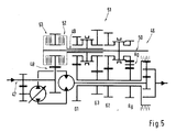
- the embodiment of a power split transmission 46 shown in FIG. 5 has a drive shaft 47, which is connected via a spur gear 48 to a first gear shaft 49 and a second gear shaft 50 of a Doppellkupplungsgetriebes 51 in operative connection.
- the dual clutch transmission 51 includes a first clutch 52 and a second clutch 53 that cooperate with the first transmission shaft 49 and the second transmission shaft 50, respectively.
Landscapes
- Engineering & Computer Science (AREA)
- General Engineering & Computer Science (AREA)
- Mechanical Engineering (AREA)
- Structure Of Transmissions (AREA)
- Arrangement Of Transmissions (AREA)
- Control Of Transmission Device (AREA)
- Transmission Devices (AREA)
Abstract
Description
- Die Erfindung bezieht sich auf ein Leistungsverzweigungsgetriebe für Kraftfahrzeuge nach dem Oberbegriff des Patentanspruchs 1.
- Es ist ein hydromechanisches Getriebe bekannt, US 3,979,972, das nach Art eines Leistungsverzeigungsgetriebes ausgebildet ist und eine mit einer Brennkraftmaschine verbundene Eingangswelle und eine Ausgangswelle umfasst. Dabei sind in einem ersten Zweig zwischen Eingangswelle und Ausgangswelle Kupplungen und Planetengetriebe vorgesehen sind, wogegen in einem zweiten Zweig ein hydrostatischer Antrieb arbeitet, der mit Stirnradgetrieben in Wirkverbindung steht und zwei hintereinander liegende Pumpmotoren aufweist.
- In der DE 199 54 894 A1 wird ein Leistungsverzweigungsgetriebe behandelt, das für Traktoren, rad- und kettengetriebene Arbeitsmaschinen und Nutzkraftwagen geeignet ist. Das Leistungsverzweigungsgetriebe besitzt einen mechanischen Zweig, einen hydrostatischen Zweig und ein oder mehrere Planetengetriebe, über die der mechanische Leistungsanteil und der hydrostatische Leistungsanteil wieder zusammengeführt werden.
- Aus der DE 101 28 853 A1 geht ein Kraftfahrzeug hervor, das einen Antriebsstrang mit einer Antriebseinheit, ein Getriebe und eine Kupplungseinrichtung zur Momentenübertragung zwischen der Antriebseinheit und dem Getriebe aufweist. Die Kupplungseinrichtung ist als Mehrfach-Kupplungseinrichtung, insbesondere Doppel-Kupplungseinrichtung, mit einer ersten Getriebeeingangswelle zugeordneten ersten Kupplungsanordnung und einer zweiten Getriebeeingangswelle zugeordneten zweiten Kupplungsanordnung ausgeführt.
- Gemäß der DE 101 28 853 A1 ist in ein Kraftfahrzeug ein Antriebsstrang mit einer Brennkraftmaschine eingebaut, die mit einem Doppelkupplungsgetriebe oder Lastschaltgetriebe zusammenwirkt. Zwischen Brennkraftmaschine und vorstehendem Getriebe ist eine Doppelkupplung vorgesehen, von der aus sich eine Eingangswelle zu besagtem Getriebe erstreckt. An einer Vorgelegewelle des Getriebes ist eine Ausgangswelle vorgesehen, die Räder einer Hinterachse antreibt.
- Es ist Aufgabe der Erfindung ein hochwirksames Lastschaltgetriebe für Kraftfahrzeuge zu schaffen, das vielfältige Anwendungsmöglichkeiten bietet und sich durch einfachen konstruktiven Getriebeaufbau auszeichnet.
- Diese Aufgabe wird erfindungsgemäß durch die Merkmale des Patentanspruchs 1 gelöst. Weitere, die Erfindung ausgestaltende Merkmale sind in den Unteransprüchen bzw. Anspruch 20 enthalten, der ein Verfahren zum Betrieb eines Lastschaltgetriebes unter Schutz stellt.
- Die mit der Erfindung hauptsächlich erzielten Vorteile sind darin zu sehen, dass ein stufenlos arbeitendes leicht herstellbares Leistungsverzweigungsgetriebe konzipiert ist, das mit Zugkraft- unterbrechungsfreier Veränderung der Getriebe-Übersetzung von maximaler Geschwindigkeit bei Rückwärtsfahrt bis zur maximalen Geschwindigkeit bei Vorwärtsfahrt arbeitet, wobei es möglich ist aus dem Stillstand anzufahren. Dabei ist genaues Positionieren und Rangieren des Kraftfahrzeugs durch den Steuerantrieb, vorzugsweise die Hydrostateinrichtung sichergestellt. Auch kann die Größe des Hydrostateinrichtung primär durch die erforderlichen Zugkräfte und den zulässigen Differenzdruck der Hydrostateinrichtung bestimmt werden. Dank der Übersetzungen im Summierplanetengetriebe besteht die Möglichkeit das Verdrängungsvolumen im Konstantmotor der Hydrostateinrichtung relativ klein zu halten. Darüber hinaus wird ein vorzüglicher Getriebe Wirkungsgrad erzielt, und zwar durch geringe hydrostatische Leistungsanteile, insbesondere bei höheren Gängen und höheren Geschwindigkeiten. Darstellbar sind ferner erforderliche Getriebespreizungen mit beliebiger Anzahl von mechanischen Übersetzungsstufen. Schließlich ist in Verbindung mit der Hydrosteinrichtung auch noch eine Retarderfunktion verwirklichbar. Darüber hinaus ist das Leistungsverzweigungsgetriebe für Arbeitsmaschinen - Traktoren, Baumaschinen -, Handlingfahrzeugen - Telehandler, Stapler - und Fahrzeuge für Stop and Go Betrieb - Stadtbusse, Zustellfahrzeuge, Kommunalfahrzeuge - geeignet. Und schließlich kann besagtes Getriebe bei Personenkraftwagen und Nutzfahrzeugen eingesetzt werden, wo besondere Anforderungen bezüglich Fahr- und Bedienkomfort bestehen.
- In der Zeichnung werden Ausführungsbeispiele der Erfindung gezeigt, die nachstehend näher beschrieben sind.
- Es zeigen
- Fig. 1 einen schematischen Längsschnitt durch eine erste Ausführungsform eines Leistungsverzweigungsgetriebes,
- Fig. 2 ein Geschwindigkeitsdiagramm für das Leistungsverzweigungsgetriebe nach Fig. 1.
- Fig. 3 eine Ansicht entsprechend Fig. 1 einer zweiten Ausführungsform eines Leistungsverzweigungsgetriebes,
- Fig. 4 ein Geschwindigkeitsdiagramm für das Leistungsverzeigungsgetriebe nach Fig. 3,
- Fig. 5 eine Ansicht entsprechend Fig. 1 einer dritten Ausführungsform eines Leistungsverzweigungsgetriebes.
- Ein nicht näher dargestelltes Kraftfahrzeug, das durch eine Arbeitsmaschine - Traktor, Baumaschine -, ein Handlingfahrzeug - Telehandler, Stapler oder ein bspw. im Stop and Go Betrieb wirkendes Fahrzeug - Stadtbus, Zustellfahrzeug oder Kommunalfahrzeug - weist ein Leistungsverzweigungsgetriebe 1 mit einer von einer Brennkraftmaschine angetrieben Eingangswelle 2 auf. Das Leistungsverzweigungsgetriebe 1 ist mit mehreren Zweigen ZI, ZII und ZIII ausgestattet, wovon der erster Zweig I ein vier Gänge G1, G2, G3 und G4 umfassendes Lastschaltgetriebe 3 besitzt - Fig. 1 -. Der zweite Zweig II ist als Steuereinrichtung 4 ausgebildet, die unter Vermittlung einer den dritten Zweig III bildenden als Summierplanetengetriebe 5 ausgebildeten Getriebeeinheit mit einer Abtriebswelle 6 zusammenarbeitet.
- Die Steuereinrichtung 4 ist in der Weise ausgebildet, dass beim Anfahrvorgang des Kraftfahrzeugs einerseits die Drehrichtung der Abtriebswelle 6 für Vorwärtsfahrt Rückwärtsfahrt veränderbar ist. Andererseits lässt sich beim Anfahrvorgang und geschalteten Gängen - G1, G2, G3 und G4 - die Abtriebswelle 6 stufenlos verstellen. Die Steuereinrichtung 4 wird durch eine Hydrostateinrichtung 7 gebildet, wobei auch denkbar ist für die Steuereinrichtung 4 einen Elektromotor zu verwenden.
- Die Hydrostateinrichtung 7 besitzt eine eine Stelleinrichtung Se aufweisende Verstellpumpe 8 mit und einen Konstantmotor 9 (bei definierten Anforderungen kann der Konstantmotor auch ein Verstellmotor sein) ; letztere können zu einer kompakten und einfach zu montierenden Baueinheit 10 zusammengefasst sein. Die Verstellpumpe 8 wird von einem zwei Zahnräder 11 und 12 umfassenden Stirnradgetriebe 13 angetrieben, das mit der Eingangswelle 2 zusammenarbeitet .Dabei ist Zahnrad 11 mit der Eingangswelle 2 und Zahnrad 12 mit der einer ersten Welle 14 der Verstellpumpe 8 verbunden
- Der Konstantmotor 9 der Hydrostateinrichtung 7 treibt über eine zweite Welle 15 ein Sonnenrad 16 des drei Wellen umfassenden Summierplanetengetriebes 5 an. Ein Hohlrad 17 des Summierplanetengetriebes 5 wirkt mit einer lastschaltbaren Hohlradkupplung 18 zusammen, die an einem Gehäuse 19 befestigt ist. Das Hohlrad 17 ist mit einer Vorgelegewelle 20 des nach Art eines Doppelkupplungsgetriebes 21 ausgebildeten Lastschaltgetriebes 3 verbunden, welche Vorgelegewelle 20 Zahnräder 22, 23, 24 und 25 für die Gänge G1, G2, G3 und G4 trägt. Die Vorgelegewelle 20 ist als Hohlwelle 26 ausgeführt in der die zweite Welle 15, die sich zwischen Konstantmotor 9 und Sonnenrad 16 des Summierplanetengetriebes 5 erstreckt, verläuft.
- Die Eingangswelle 2 des Leistungsverzweigungsgetriebes 1 wirkt mittels einer ersten Schaltkupplung 27 und einer zweiten Schaltkupplung 28 des Doppelkupplungsgetriebes 21 zusammen. Hiervon ist die erste lastschaltbare Schaltkupplung 27 mit einer ersten Getriebewelle 29 und die zweite lastschaltbare Schaltkupplung 28 mit einer zweiten Getriebewelle 30 gekoppelt. Zur konstruktiven Vereinfachung ist die erste Getriebewelle 29 als Hohlwelle 31 gestaltet, die die zweite Getriebewelle 30 zumindest abschnittsweise umgibt. Auf der ersten Getriebewelle 29 und der zweiten Getriebewelle 30 sind Losräder 32, 33, 34 und 35 gelagert, wobei auf der ersten Getriebewelle 29 die Losräder 32 und 33 für die Gänge G1 und G3 gelagert sind; auf der zweiten Getriebewelle 30 die Losräder 34 und 35 für die Gänge G2 und G4. Zwischen den Losrädern 32 und 33 bzw. den Losrädern 34 und 35 sind Gleichlaufeinrichtungen 36 und 37 vorgesehen, die bei Zuschaltung der Gänge G1, G2, G3 und G4 wirksam werden. Die Gleichlaufeinrichtungen 36 und 37 können durch entsprechend ausgeführte Schaltkupplungen ersetzt werden.
- Beim Anlassvorgang der auf das Leistungsverzeigungsgetriebes 1 einwirkenden und mit Konstantdrehzahl arbeitender Brennkraftmaschine sind die erste Schaltkupplung 27 und die zweite Schaltkupplung 28 des Doppelkupplungsgetriebes 21 geöffnet; ebenso die Hohlradkupplung 18. Über das Stirnradgetriebe 13 wird die Verstellpumpe 8 der Hydrostateinrichtung 7 entsprechend der Drehzahl der Brennkraftmaschine angetrieben. Die Stelleinrichtung Se der Verstellpumpe 8 ist auf einen Schwenkwinkel mit der Kennzeichnung N (=0) gestellt; es erfolgt keine Förderung von Hydraulikmedium zum Konstantmotor 9. Die zweite Welle 15 des Konstantmotors 9 steht still bzw. weist Drehzahl 0 auf. Durch Schließen der Hohlradkupplung 18 wird das Hohlrad 17 am Summierplanetengetriebe 5 mit dem Gehäuse 19 verbunden und der Kraftfluss zwischen Brennkraftmaschine und den Rädern des Kraftfahrzeugs geschlossen. Dabei wird die Drehzahl und die Drehrichtung des Abtriebswelle 6 allein durch die Drehzahl und Drehrichtung des Sonnenrads 16 des Summierplanetengetriebes 5 bestimmt. Unter dem Einfluss der Veränderung des geförderten Ölvolumens der Verstellpumpe 8 durch Verstellung des Schwenkwinkels der Stelleinrichtung Se wird der Konstantmotor 9 mit Hydraulkmedium versorgt, welcher Konstantmotor 9 das Sonnenrad 16 antreibt. Aus dem Stillstand des Kraftfahrzeugs - Ausgangsgröße des Anfahrvorgangs - wird besagtes Kraftfahrzeug rein hydrostatisch angetrieben. Aufgrund der Hydrostateinrichtung 7 besteht die Möglichkeit das Kraftfahrzeug in beide Fahrtrichtungen - Vorwärtsfahrt und Rückwärtsfahrt - in Abhängigkeit der gewählten Übersetzungsverhältnisse des Summierplanetengetriebes 5 und der Drehzahlauslegung der Hydrostateinrichtung 7 zu betreiben.
- Nach dem Anfahrvorgang über die Hydrostateinrichtung 7 erfolgt ein Umschaltvorgang in den ersten Gang G1, wobei über die Gleichlaufeinrichtung 36 das Losrad 32 mit der ersten Getriebewelle 29 drehfest verbunden wird. In diesem Betriebszustand wird die Hohlradkupplung 19 geöffnet und die erste Schaltkupplung 27 wird überlappend geschlossen. Dadurch wird das Hohlrad 17 des Summierplanetengetriebes 5 mit der ersten Getriebewelle 29 verbunden und eine definierte Drehzahl erreicht. Während dieses Umschaltvorgangs wird durch anpassende Verstellung des Schwenkwinkels der Stelleinrichtung Se der Verstellpumpe 8 die Drehzahl und die Drehrichtung des Konstantmotors 9 permanent an die Drehzahländerung des Hohlrads 17 angepasst, und zwar mit dem Ergebnis dass nach Beendigung des Umschaltvorgangs eine vergleichbare Getriebe- Gesamt-Übersetzung wie beim Antrieb über die Hydrostateinrichtun 7 vorliegt. In diesem Betriebszustand dreht sich das Sonnenrad 16 in Gegenrichtung zum Hohlrad 17. Hierbei ist erwähnenswert, dass durch Veränderung der Drehzahl des Sonnenrads 16 von Drehung entgegen der Drehrichtung des Hohlrads 17 und in gleicher Richtung des Hohlrads 16, und zwar jeweils bis zur maximalen Drehzahl die Übersetzung des Lastschaltgetriebes 1 stufenlos eingestellt werden kann.
- Nach erreichen der maximalen Geschwindigkeit im erste Gang G1 dreht das Hohlrad 17 entsprechend der im Doppelkupplungsgetriebe 21 gewählten Ubersetzungsstufe und das Sonnenrad 16 dreht in gleicher Richtung wie das Hohlrad 17 mit entsprechend hoher Drehzahl, und es erfolgt der Umschaltvorgang in den nächst höheren Gang mit folgendem Ablauf:
- Gleichlaufbeginn des nächsten Gangs - G2, G3, G4 - durch Betätigung der Gleichlaufeinrichtungen 36 und 37 an einer der lastfreien ersten oder zweiten Getriebewellen 29 oder 30;
- Schalten von einer der Getriebewellen - 29 oder 30 - auf die andere Getriebewelle - 29 oder 30 - durch überlappendes Öffnen und Schließen der Schaltkupplungen - 27 oder 28 - und gleichzeitiger Anpassung der Drehzahl des Konstantmotors 9, damit am Ende des Umschaltvorgangs wiederum ungefähr dieselbe Übersetzung wie vor dem Umschaltvorgang vorliegt;
- Nachdem der Umschaltvorgang vollzogen ist, erfolgt die Veränderung des Getriebe-Übersetzungsverhältnisses durch Veränderung der Drehzahl des Konstantmotors 9.
- Das Schalten etwaiger weiterer höherer Gänge bzw. das Schalten niederer Gänge erfolgt analog.
- In Fig. 2 ist ein Geschwindigkeitsschaubild des Leistungsverzweigungsgetriebes 1 dargestellt, wobei auf der Abszisse 38 die Geschwindigkeit in km/h und auf der Ordinate 39 die Funktion des Hydrostatantriebs 7 alleine bzw. bei geschalteten Gängen G1, G2, G3 und G4 aufgetragen sind. Danach ist beim Anfahrvorgang des Kraftfahrzeugs die Hydrostateinrichtung 7 für Vorwärtsfahrt und Rückwärtsfahrt m Bereich von 0 km/h bis jeweils ca. 8 km/h allein stufenlos wirksam - Horizontaler Balken BI -. Darüber hinaus arbeitet die Hydrostateinrichtung 7 in den Gängen G1, G2, G3 und G4 in Geschwindigkeitsbereichen gemäß den horizontalen Balken BII, III, BIV und BV d.h.: G1 von 2 bis 16 km/h, G2 von 12 bis 26 km/h, G3 von 22 bis 36 km/h und G4 von 34 bis 48 km/h.
- Nach Fig. 3 ist ein Leistungsverzweigungsgetriebe 40 prinzipiell wie das Leistungsverzweigungsgetriebe 1 gemäß Fig. 1 aufgebaut. Allerdings ist das Leistungsverzweigungsgetriebe 40 mit drei Gängen G1, G2 und G3 und einem mechanischen Rückwärtsgang Rg versehen, der zwischen einer zweiten Getriebewelle 41 und einer Vorgelegewelle 42 eines Doppelkupplungsgetriebes 43 angeordnet ist; eine Hydrostateinrichtung ist mit 44 und eine Abtriebswelle mit 45 bezeichnet. Aus dem Schaubild gemäß Fig. 4, das ähnlich dem Schaubild in Fig. 2 ist, geht hervor, dass im zugeschalteten Rückwärtsgang Rg mittels Hydrostateinrichtung 44 Geschwindigkeiten von 8 bis 20 km/h erzielbar sind - Balken BI -. Bei reinem Betrieb mit Hydrostatantrieb 45, der durch den Balken BII dargestellt ist, werden beim Anfahrvorgang Geschwindigkeiten von 0 bis 8 km/h, und zwar in Vorwärtsfahrt und Rückwärtsfahrt erreicht. Die Geschwindigkeitsbereiche für die Gänge G1, G2 und G3 werden durch die Balken BIII, BIV und BV verdeutlicht.
- Die in Fig. 5 gezeigte Ausführungsform eines Leistungsverzweigungsgetriebes 46 weist eine Antriebswelle 47 auf , die über ein Stirnradgetriebe 48 mit einer ersten Getriebewelle 49 und einer zweiten Getriebewelle 50 eines Doppellkupplungsgetriebes 51 in Wirkverbindung steht. Schließlich umfasst das Doppellkupplungsgetriebe 51 eine erste Schaltkupplung 52 und eine zweite Schaltkupplung 53, die mit der ersten Getriebewelle 49 bzw. der zweiten Getriebewelle 50 zusammenarbeiten.
Claims (20)
- Leistungsverzweigungsgetriebe für Kraftfahrzeuge mit einer Brennkraftmaschine, die eine Eingangswelle des Leistungsverzeigungsgetriebes antreibt, welches Leistungsverzweigungsgetriebe mehrere wenigstens ein Lastschaltgetriebe mit einer Anzahl von Gängen umfassende Zweige und eine Abtriebsswelle aufweist, dadurch gekennzeichnet, dass zumindest einer der Zweige (ZI, ZII oder ZIII) mit einer Steuereinrichtung (4) versehen ist, mit der beim Anfahrvorgang des Kraftfahrzeugs die Drehrichtung der Abtriebswelle (6) veränderbar ist, wobei beim Anfahrvorgang und geschalteten Gängen des mit der Eingangswelle (2) verbundenen Lastschaltgetriebes (3) über die Steuereinrichtung (4) die Drehzahl der Abtriebswelle (6) stufenlos beeinflussbar ist.
- Leistungsverzweigungsgetriebe nach Anspruch 1, dadurch gekennzeichnet, dass das Lastschaltgetriebe (3) einen ersten Zweig (ZI) und die Steuereinrichtung (4) einen zweiten Zweig (ZII) bildet, welche Steuereinrichtung (4) mit einem dritten ein Summierungsplanetengetriebe (5) umfassenden Zweig (ZIII) zusammenarbeitet.
- Leistungsverzeigungsgetriebe nach Anspruch 2, dadurch gekennzeichnet, dass die Steuereinrichtung (4) durch eine Hydrostateinrichtung (7; 44) gebildet wird.
- Leistungsverzweigungsgetriebe nach Anspruch 2, dadurch gekennzeichnet, dass die Steuereinrichtung (4) durch einen Elektroantrieb gebildet wird.
- Leistungsverzweigungsgetriebe nach Anspruch 3, dadurch gekennzeichnet, dass die Hydrostateinrichtung (7; 44) eine Verstellpumpe (8) und einen Konstantmotor (9) besitzt.
- Leistungsverzweigungsgetriebe nach Anspruch 5, dadurch gekennzeichnet, dass die Verstellpumpe (8) und der Konstantmotor (9) der Hydrostateinrichtung (7; 44) zu einer Baueinheit (10) zusammengefasst sind.
- Leistungsverzweigungsgetriebe nach Anspruch 6, dadurch gekennzeichnet, dass die Verstellpumpe (8) der Hydrostateinrichtung (7) über ein Stirnradgetriebe (13) mit der Eingangswelle (2) zusammenarbeitet.
- Leistungsverzweigungsgetriebe nach den Ansprüchen 2 und 6, dadurch gekennzeichnet, dass der Konstantmotor (9) der Hydrostateinrichtung (7) über eine zweite Welle (15) ein Sonnenrad (16) des Summierplanetengetriebes (5) antreibt.
- Leistungsverzweigungsgetriebe nach den Ansprüchen 2 und 8, dadurch gekennzeichnet, dass das Summierplanetengetriebe (5) drei Wellen umfasst.
- Leistungsverzeigungsgetriebe nach den Ansprüchen 2 und 8, dadurch gekennzeichnet, dass ein Hohlrad (17) des Summierplanetengetriebes (5) mit einer schaltbaren Hohlradkupplung (18) zusammenarbeitet.
- Leistungsverzeigungsgetriebe nach Anspruch 10, dadurch gekennzeichnet, dass das Hohlrad (17) des Summierplanetengetriebes (5) mit einer Zahnräder (22, 23, 25 und 25) tragenden Vorgelegewelle (20) des Lastschaltgetriebes (3) verbunden ist.
- Leistungsverzeigungsgetriebe nach den Ansprüchen 1, 2 und 11, dadurch gekennzeichnet, dass das Lastschaltgetriebe (3) nach Art eines Doppelkupplungsgetriebes (21) ausgebildet ist.
- Leistungsverzeigungsgetriebe nach den Ansprüchen 8 und 11, dadurch gekennzeichnet, dass die Vorgelegewelle (20) des Lastschaltgetriebes (3) durch eine Hohlwelle (26) gebildet wird, in der zweite Welle (15) zwischen Konstantmotor (9) und Sonnenrad (16) verläuft.
- Leistungsverzweigungsgetriebe nach den Ansprüchen 1 und 12, dadurch gekennzeichnet, dass die Eingangswelle (2) mit einer ersten Schaltkupplung (27) und einer zweiten Schaltkupplung (28) verbunden ist, wovon die erste Schaltkupplung (27) mit einer ersten Getriebewelle (29) und die zweite Schaltkupplung (28) mit einer zweiten Getriebewelle (30) gekoppelt ist, auf welchen ersten und zweiten Getriebewellen (29 und 30) Losräder (32, 33, 33 und 34) gelagert sind.
- Leistungsverzweigungsgetriebe nach Anspruch 14, dadurch gekennzeichnet, dass die erste Getriebewelle (29) als Hohlwelle (31) ausgeführt ist, die die zweite Getriebewelle (30) umgibt.
- Leistungsverzweigungsgetriebe nach Anspruch 14, dadurch gekennzeichnet, dass die ersten und zweiten Getriebewellen (29 und 30) mit Gleichlaufeinrichtungen (36 und 37) für die die Losräder (32 bis 35) versehen sind.
- Leistungsverzweigungsgetriebe nach Anspruch 14, dadurch gekennzeichnet, dass die ersten und die zweiten Getriebewellen (29 und 30) mit lastschaltbaren Kupplungen für die Losräder (32 bis 35) versehen sind.
- Leistungsverzweigungsgetriebe nach den 1, 2 und 12, dadurch gekennzeichnet, dass zwischen wenigstens der zweiten Getriebewelle (41) und der Vorgelegewelle (42) eine Rückwärtsgang (Rg) vorgesehen ist, mit dem die Drehrichtung der Vorgelegewelle (42) umkehrbar ist.
- Leistungsverzweigungsgetriebe nach den Ansprüchen 1 und 12 , dadurch gekennzeichnet, dass das Doppelkupplungsgetriebe (43) unter Vermittlung eines Stirnradgetriebes (43) mit der Antriebswelle (47) zusammenwirkt.
- Verfahren zum Betrieb eines Leistungsverzweigungsgetriebes für Kraftfahrzeuge mit einer Brennkraftmaschine, die eine Eingangswelle des Leistungsverzeigungsgetriebes antreibt, welches Leistungsverzweigungsgetriebe mehrere wenigstens ein Lastschaltgetriebe mit einer Anzahl von Gängen umfassende Zweige und eine Abtriebswelle aufweist, dadurch gekennzeichnet, dass zumindest einer der Zweige (ZI, ZII oder ZIII) das Leistungsverzweigungsgetriebe (1) in der Weise steuert, dass beim Anfahrvorgang des Kraftfahrzeugs die Drehrichtung der Abtriebswelle (6) veränderbar ist, wobei beim Anfahrvorgang und geschalteten Gängen (G1, G2, G3 und G4) des mit der Eingangswelle (2) verbundenen Lastschaltgetriebes (3) die Drehzahl der Abtriebswelle (6) stufenlos beeinflussbar ist.
Applications Claiming Priority (1)
| Application Number | Priority Date | Filing Date | Title |
|---|---|---|---|
| ATA1360/2004A AT414345B (de) | 2004-08-10 | 2004-08-10 | Leistungsverzweigungsgetriebe für kraftfahrzeuge |
Publications (3)
| Publication Number | Publication Date |
|---|---|
| EP1626206A2 true EP1626206A2 (de) | 2006-02-15 |
| EP1626206A3 EP1626206A3 (de) | 2006-12-27 |
| EP1626206B1 EP1626206B1 (de) | 2010-10-27 |
Family
ID=35134417
Family Applications (1)
| Application Number | Title | Priority Date | Filing Date |
|---|---|---|---|
| EP05016035A Expired - Lifetime EP1626206B1 (de) | 2004-08-10 | 2005-07-23 | Leistungsverzweigungsgetriebe für Kraftfahrzeuge |
Country Status (5)
| Country | Link |
|---|---|
| US (1) | US7361111B2 (de) |
| EP (1) | EP1626206B1 (de) |
| JP (1) | JP2006052853A (de) |
| AT (2) | AT414345B (de) |
| DE (2) | DE202005021249U1 (de) |
Cited By (10)
| Publication number | Priority date | Publication date | Assignee | Title |
|---|---|---|---|---|
| DE102007017176A1 (de) * | 2007-04-12 | 2008-10-16 | Zf Friedrichshafen Ag | Hydrostatisch-mechanisches Leistungsverzweigungsgetriebe |
| DE102008015276A1 (de) | 2008-03-20 | 2009-09-24 | Linde Material Handling Gmbh | Leistungsverzweigungsgetriebe |
| DE102008047619A1 (de) | 2008-09-17 | 2010-04-15 | Linde Material Handling Gmbh | Leistungsverzweigungsgetriebe |
| CH700104A1 (de) * | 2008-12-12 | 2010-06-15 | Pitorqa Gmbh | Stufenloses Fahr- und Anfahrgetriebe. |
| WO2011000472A1 (de) * | 2009-07-01 | 2011-01-06 | Robert Bosch Gmbh | Antriebssystem und verfahren zum wechseln von fahrbereichen des antriebssystems |
| EP2426376A2 (de) | 2010-09-02 | 2012-03-07 | Linde Material Handling GmbH | Fahrantrieb mit einem Antriebsmotor und einer Getriebeeinrichtung mit Schaltgetriebe und Variator |
| AT512975A1 (de) * | 2012-03-27 | 2013-12-15 | Reformwerke Bauer & Co Ges M B H | Hydromechanisches Synchrongetriebe |
| WO2014095317A1 (de) * | 2012-12-17 | 2014-06-26 | Linde Hydraulics Gmbh & Co. Kg | Leistungsverzweigungsgetriebe mit verschiedenen betriebszuständen |
| DE102013208201B4 (de) * | 2013-05-06 | 2016-03-10 | Zf Friedrichshafen Ag | Lastschaltgetriebe eines Kraftfahrzeugs und Verfahren zur Schaltsteuerung eines Lastschaltgetriebes |
| EP3754226A1 (de) * | 2019-06-19 | 2020-12-23 | Deere & Company | Lastschaltgetriebe |
Families Citing this family (28)
| Publication number | Priority date | Publication date | Assignee | Title |
|---|---|---|---|---|
| US7873457B2 (en) * | 2006-04-26 | 2011-01-18 | Magna Steyr Fahrzeugtechnik Ag & Co Kg | Clutch control system for power transfer unit in four-wheel drive vehicle |
| US7611433B2 (en) * | 2006-05-05 | 2009-11-03 | Magna Powertrain Usa, Inc. | Dual clutch hybrid powershift transmission |
| JP4910550B2 (ja) * | 2006-08-03 | 2012-04-04 | トヨタ自動車株式会社 | 変速機の変速比制御装置 |
| US8235853B2 (en) * | 2006-10-18 | 2012-08-07 | Magna Powertrain Inc. | Hybrid transmissions with planetary gearsets |
| JP5028559B2 (ja) * | 2007-01-23 | 2012-09-19 | 株式会社 神崎高級工機製作所 | 作業車用変速機構 |
| US8313406B2 (en) * | 2007-04-06 | 2012-11-20 | Borgwarner Inc. | Dual clutch transmission |
| DE102007059321A1 (de) * | 2007-12-07 | 2009-06-10 | Hytrac Gmbh | Leistungsverzweigungsgetriebe |
| DE102008000646A1 (de) * | 2008-03-13 | 2009-09-17 | Zf Friedrichshafen Ag | Anordnung zum Schalten von zumindest zwei Losrädern |
| DE102008021010B4 (de) | 2008-04-25 | 2010-02-25 | Lohmann & Stolterfoht Gmbh | Leistungsverzweigungsgetriebe |
| JP5124371B2 (ja) * | 2008-07-03 | 2013-01-23 | ザウアーダンフォス・ダイキン株式会社 | 変速装置 |
| GB0910242D0 (en) * | 2009-06-15 | 2009-07-29 | Bamford Excavators Ltd | Hybrid transmission |
| KR101145624B1 (ko) | 2009-11-23 | 2012-05-15 | 현대자동차주식회사 | 토크 분기형 자동변속기 |
| DE102010029865B4 (de) * | 2010-06-09 | 2023-01-12 | Zf Friedrichshafen Ag | Stufenloses Leistungsverzweigungsgetriebe |
| EP2466168A1 (de) | 2010-12-16 | 2012-06-20 | VDS Getriebe GmbH | Einrichtung zur Aufteilung der Antriebsleistung |
| DE102012205823A1 (de) | 2012-04-11 | 2013-10-17 | Zf Friedrichshafen Ag | Antriebsvorrichtung eines Fahrzeugs und Verfahren zu dessen Betrieb |
| DE102012205825A1 (de) * | 2012-04-11 | 2013-10-17 | Zf Friedrichshafen Ag | Anfahr- und Retarderelement sowie Verfahren zum Betrieb eines Anfahr- und Retarderelements |
| DE102012108857B4 (de) * | 2012-09-20 | 2022-01-13 | Linde Hydraulics Gmbh & Co. Kg | Hydrostatische Startereinrichtung eines Verbrennungsmotors |
| JP6170719B2 (ja) * | 2013-04-26 | 2017-07-26 | 株式会社小松製作所 | ホイールローダ |
| DE102014220126B4 (de) | 2014-10-06 | 2022-12-01 | Schaeffler Technologies AG & Co. KG | Hybridkupplung für eine Doppelgetriebeeinheit eines Kraftfahrzeugs und Verfahren zum verlustarmen Übertragen eines Drehmoments mittels der Hybridkupplung |
| DE102015221554B4 (de) | 2015-11-03 | 2020-03-26 | Audi Ag | Getriebe und Verfahren zum Betreiben eines solchen |
| CN105240481A (zh) * | 2015-11-18 | 2016-01-13 | 山东农业大学 | 一种大功率拖拉机液压机械无级变速器 |
| KR101779129B1 (ko) | 2016-05-17 | 2017-09-18 | (주)스마텍 | 지게차용 무단변속기 |
| US9874279B1 (en) | 2016-10-11 | 2018-01-23 | Cnh Industrial America Llc | System and method for operating a continuously variable transmission of a work vehicle in a hydrostatic bypass mode |
| US12072008B2 (en) | 2018-10-19 | 2024-08-27 | Kanzaki Kokyukoki Mfg. Co., Ltd. | Transmission structure and working vehicle |
| EP3715671B1 (de) | 2018-10-19 | 2023-12-06 | Kanzaki Kokyukoki Mfg. Co., Ltd. | Getriebestruktur und arbeitsfahrzeug |
| KR102070395B1 (ko) * | 2018-12-28 | 2020-01-28 | 대구가톨릭대학교산학협력단 | 전기차용 3단 변속기 |
| US11971092B2 (en) * | 2022-03-07 | 2024-04-30 | Dana Italia S.R.L. | Hydromechanical transmission and control method |
| CN115056648B (zh) * | 2022-07-06 | 2024-07-19 | 潍柴动力股份有限公司 | 传动系统及具有其的车辆 |
Citations (13)
| Publication number | Priority date | Publication date | Assignee | Title |
|---|---|---|---|---|
| USRE27307E (en) | 1969-02-27 | 1972-03-14 | Extended range hydraulic transmission | |
| US3918325A (en) | 1974-01-21 | 1975-11-11 | Clark Equipment Co | Extended range dual-path transmission |
| US3979972A (en) | 1974-02-06 | 1976-09-14 | Toyota Jidosha Kogyo Kabushiki Kaisha | Hydromechanical transmission |
| USRE33126E (en) | 1985-10-18 | 1989-12-12 | Gear assisted continuously variable transmission | |
| EP0564003A1 (de) | 1987-05-12 | 1993-10-06 | Jarchow, Friedrich, Prof. Dr.-Ing. | Stufenlos wirkendes hydrostatisch-mechanisches Lastschaltgetriebe |
| DE19905447A1 (de) | 1998-02-09 | 1999-12-30 | Michael Meyerle | Stufenloses Getriebe mit Leistungsverzweigung |
| DE19954894A1 (de) | 1999-05-25 | 2000-12-21 | Liebherr Markus | Leistungsverzweigungsgetriebe |
| DE19950696A1 (de) | 1999-10-21 | 2001-04-26 | Volkswagen Ag | Doppelkupplungsgetriebe und Verfahren zur Steuerung eines automatisierten Doppelkupplungsgetriebes |
| DE10021760A1 (de) | 2000-05-04 | 2001-11-08 | Zahnradfabrik Friedrichshafen | Leistungsverzweigtes stufenloses Getriebe |
| US6361463B1 (en) | 1999-05-17 | 2002-03-26 | Kanzaki Kokyukoki Mfg. Co., Ltd. | Drive transmission for vehicles |
| DE10128853A1 (de) | 2001-06-15 | 2002-12-19 | Zf Sachs Ag | Kraftfahrzeug und Verfahren zum Betrieb des Fahrzeugs, insbesondere zum Freischaukeln oder/und Rangieren |
| US20030060318A1 (en) | 2001-09-27 | 2003-03-27 | Jatco Ltd | Torque split infinitely variable transmission |
| DE10248400A1 (de) | 2002-10-17 | 2004-04-29 | Zf Friedrichshafen Ag | Leistungsverzweigtes stufenloses Automatgetriebe |
Family Cites Families (15)
| Publication number | Priority date | Publication date | Assignee | Title |
|---|---|---|---|---|
| US2962915A (en) * | 1954-08-18 | 1960-12-06 | Reiners Walter | Mechanical power converter of variable transmission ratio |
| US3132533A (en) * | 1960-11-18 | 1964-05-12 | Ford Motor Co | Infinitely variable, geared hydrostatic power transmission mechanism |
| US3212358A (en) * | 1962-01-16 | 1965-10-19 | Lalio George M De | Continuously variable power transmission |
| US3306129A (en) * | 1965-04-12 | 1967-02-28 | Lalio George M De | Extended range hydraulic transmission |
| US3580107A (en) * | 1968-10-21 | 1971-05-25 | Urs Systems Corp | Transmission |
| US3988949A (en) * | 1974-06-12 | 1976-11-02 | Orshansky Transmission Corporation | Split-torque power transmission |
| DE2724965A1 (de) * | 1977-06-02 | 1978-12-07 | Sundstrand Corp | Lastschaltgetriebe |
| DE3624989A1 (de) * | 1986-07-24 | 1988-02-04 | Man Nutzfahrzeuge Gmbh | Getriebe fuer kraftfahrzeuge |
| ES2024874A6 (es) * | 1990-06-20 | 1992-03-01 | Aragonesa Equip Automoviles Sa | Cambio de velocidad continuo. |
| DE4104170C2 (de) * | 1991-02-12 | 1994-09-29 | Stroemungsmaschinen Gmbh | Hydrodynamisch-mechanisches Lastschaltgetriebe in Vorgelegebauweise |
| US5890981A (en) * | 1996-11-25 | 1999-04-06 | Caterpillar Inc. | Hydromechanical transmission having three planetaries and five members |
| US5931758A (en) * | 1998-04-08 | 1999-08-03 | General Dynamics Land Systems, Inc. | Simplified multi-range hydromechanical transmission for vehicles |
| US6203463B1 (en) * | 1999-12-16 | 2001-03-20 | Caterpillar Inc. | Transmission with variable ratio utilizing three planetaries, five members, a variable speed pump, and a variable speed motor and associated method for operatively connecting components associated therewith |
| DE10358114A1 (de) * | 2002-12-23 | 2004-07-01 | Luk Lamellen Und Kupplungsbau Beteiligungs Kg | Getriebe mit stufenlos verstellbarer Übersetzung, mit oder ohne Leistungsverzweigung sowie mit und ohne E-Maschine |
| US7082850B2 (en) * | 2003-12-30 | 2006-08-01 | Eaton Corporation | Hybrid powertrain system |
-
2004
- 2004-08-10 AT ATA1360/2004A patent/AT414345B/de not_active IP Right Cessation
-
2005
- 2005-07-23 DE DE202005021249U patent/DE202005021249U1/de not_active Expired - Lifetime
- 2005-07-23 AT AT05016035T patent/ATE485985T1/de active
- 2005-07-23 DE DE502005010436T patent/DE502005010436D1/de not_active Expired - Lifetime
- 2005-07-23 EP EP05016035A patent/EP1626206B1/de not_active Expired - Lifetime
- 2005-08-09 US US11/199,179 patent/US7361111B2/en not_active Expired - Fee Related
- 2005-08-10 JP JP2005232667A patent/JP2006052853A/ja active Pending
Patent Citations (13)
| Publication number | Priority date | Publication date | Assignee | Title |
|---|---|---|---|---|
| USRE27307E (en) | 1969-02-27 | 1972-03-14 | Extended range hydraulic transmission | |
| US3918325A (en) | 1974-01-21 | 1975-11-11 | Clark Equipment Co | Extended range dual-path transmission |
| US3979972A (en) | 1974-02-06 | 1976-09-14 | Toyota Jidosha Kogyo Kabushiki Kaisha | Hydromechanical transmission |
| USRE33126E (en) | 1985-10-18 | 1989-12-12 | Gear assisted continuously variable transmission | |
| EP0564003A1 (de) | 1987-05-12 | 1993-10-06 | Jarchow, Friedrich, Prof. Dr.-Ing. | Stufenlos wirkendes hydrostatisch-mechanisches Lastschaltgetriebe |
| DE19905447A1 (de) | 1998-02-09 | 1999-12-30 | Michael Meyerle | Stufenloses Getriebe mit Leistungsverzweigung |
| US6361463B1 (en) | 1999-05-17 | 2002-03-26 | Kanzaki Kokyukoki Mfg. Co., Ltd. | Drive transmission for vehicles |
| DE19954894A1 (de) | 1999-05-25 | 2000-12-21 | Liebherr Markus | Leistungsverzweigungsgetriebe |
| DE19950696A1 (de) | 1999-10-21 | 2001-04-26 | Volkswagen Ag | Doppelkupplungsgetriebe und Verfahren zur Steuerung eines automatisierten Doppelkupplungsgetriebes |
| DE10021760A1 (de) | 2000-05-04 | 2001-11-08 | Zahnradfabrik Friedrichshafen | Leistungsverzweigtes stufenloses Getriebe |
| DE10128853A1 (de) | 2001-06-15 | 2002-12-19 | Zf Sachs Ag | Kraftfahrzeug und Verfahren zum Betrieb des Fahrzeugs, insbesondere zum Freischaukeln oder/und Rangieren |
| US20030060318A1 (en) | 2001-09-27 | 2003-03-27 | Jatco Ltd | Torque split infinitely variable transmission |
| DE10248400A1 (de) | 2002-10-17 | 2004-04-29 | Zf Friedrichshafen Ag | Leistungsverzweigtes stufenloses Automatgetriebe |
Cited By (16)
| Publication number | Priority date | Publication date | Assignee | Title |
|---|---|---|---|---|
| DE102007017176A1 (de) * | 2007-04-12 | 2008-10-16 | Zf Friedrichshafen Ag | Hydrostatisch-mechanisches Leistungsverzweigungsgetriebe |
| DE102008015276A1 (de) | 2008-03-20 | 2009-09-24 | Linde Material Handling Gmbh | Leistungsverzweigungsgetriebe |
| DE102008047619A1 (de) | 2008-09-17 | 2010-04-15 | Linde Material Handling Gmbh | Leistungsverzweigungsgetriebe |
| CH700104A1 (de) * | 2008-12-12 | 2010-06-15 | Pitorqa Gmbh | Stufenloses Fahr- und Anfahrgetriebe. |
| WO2010066059A2 (de) | 2008-12-12 | 2010-06-17 | Pitorqa Gmbh | Hybridfähiges anfahr- und fahrgetriebe |
| WO2010066059A3 (de) * | 2008-12-12 | 2010-09-23 | Pitorqa Gmbh | Hybridfähiges anfahr- und fahrgetriebe |
| US8882623B2 (en) | 2009-07-01 | 2014-11-11 | Robert Bosch Gmbh | Drive system and method for changing driving ranges of the drive system |
| WO2011000472A1 (de) * | 2009-07-01 | 2011-01-06 | Robert Bosch Gmbh | Antriebssystem und verfahren zum wechseln von fahrbereichen des antriebssystems |
| EP2426376A2 (de) | 2010-09-02 | 2012-03-07 | Linde Material Handling GmbH | Fahrantrieb mit einem Antriebsmotor und einer Getriebeeinrichtung mit Schaltgetriebe und Variator |
| DE102010036142A1 (de) | 2010-09-02 | 2012-03-08 | Linde Material Handling Gmbh | Fahrantrieb mit einem Antriebsmotor und einer Getriebeeinrichtung mit Schaltgetriebe und Variator |
| AT512975A1 (de) * | 2012-03-27 | 2013-12-15 | Reformwerke Bauer & Co Ges M B H | Hydromechanisches Synchrongetriebe |
| AT512975B1 (de) * | 2012-03-27 | 2014-04-15 | Reformwerke Bauer & Co Ges M B H | Hydromechanisches Synchrongetriebe |
| WO2014095317A1 (de) * | 2012-12-17 | 2014-06-26 | Linde Hydraulics Gmbh & Co. Kg | Leistungsverzweigungsgetriebe mit verschiedenen betriebszuständen |
| DE102013208201B4 (de) * | 2013-05-06 | 2016-03-10 | Zf Friedrichshafen Ag | Lastschaltgetriebe eines Kraftfahrzeugs und Verfahren zur Schaltsteuerung eines Lastschaltgetriebes |
| EP3754226A1 (de) * | 2019-06-19 | 2020-12-23 | Deere & Company | Lastschaltgetriebe |
| US11261944B2 (en) | 2019-06-19 | 2022-03-01 | Deere & Company | Powershift transmission |
Also Published As
| Publication number | Publication date |
|---|---|
| JP2006052853A (ja) | 2006-02-23 |
| AT414345B (de) | 2013-08-15 |
| DE502005010436D1 (de) | 2010-12-09 |
| ATA13602004A (de) | 2006-01-15 |
| US20060032321A1 (en) | 2006-02-16 |
| ATE485985T1 (de) | 2010-11-15 |
| DE202005021249U1 (de) | 2007-07-19 |
| EP1626206B1 (de) | 2010-10-27 |
| EP1626206A3 (de) | 2006-12-27 |
| US7361111B2 (en) | 2008-04-22 |
Similar Documents
| Publication | Publication Date | Title |
|---|---|---|
| AT414345B (de) | Leistungsverzweigungsgetriebe für kraftfahrzeuge | |
| EP1877681B9 (de) | Getriebe mit im direktgang abkoppelbarer vorgelegewelle | |
| EP0482039B1 (de) | Stufenlos verstellbare antriebseinheit an kraftfahrzeugen | |
| EP2207985B1 (de) | Getriebevorrichtung mit einem variator | |
| EP0081696B1 (de) | Hydrostatischmechanisches Stellkoppelgetriebe mit eingangsseitiger Leistungsverzweigung | |
| DE2633090C2 (de) | Hydrostatisch-mechanisches Getriebe mit Leistungsverzweigung für Kraftfahrzeuge | |
| DE3726080C2 (de) | ||
| WO1998034051A1 (de) | Reibradgetriebe | |
| DE4140865A1 (de) | Stufenlos einstellbares getriebe | |
| WO1989009899A1 (fr) | Boite de vitesses hydrostatique-mecanique a derivation de puissance | |
| EP0911546B1 (de) | Hydrostatisch-mechanischer Fahrantrieb | |
| EP2034221A2 (de) | Triebwerk für ein Kraftfahrzeug | |
| EP2914875A1 (de) | Doppelkupplungsgetriebe | |
| EP0818643B1 (de) | Hydrostatisch-mechanisch leistungsverzweigtes Lastschaltgetriebe | |
| DE4024063A1 (de) | Antriebsanordnung fuer ein nebenaggregat von brennkraftmaschinen in kraftfahrzeugen, insbesondere fuer eine pumpe | |
| WO2021185643A1 (de) | Leistungsverzweigtes stufenloses getriebe | |
| DE3903876C1 (en) | Transmission with a continuously variable action, a starting clutch and gears for hydrostatic-mechanical operation or hydrostatic operation | |
| EP2428700B1 (de) | Getriebevorrichtung mit wenigstens einem Variator | |
| EP0868618B1 (de) | Verfahren zum steuern eines hydrostatisch-mechanischen leistungsverzweigungsgetriebes bei unbestimmten getriebestellungen | |
| DE3836017C2 (de) | ||
| DE102020201690B3 (de) | Leistungsverzweigtes stufenloses Getriebe | |
| DE2601113B2 (de) | Fahr- und Lenkgetriebe für Raupenfahrzeuge | |
| DE2831824C2 (de) | Hydrostatisch-mechanisches Getriebe mit Leistungsverzweigung für Kraftfahrzeuge | |
| DE102020201775B3 (de) | Leistungsverzweigtes stufenloses Getriebe | |
| DE102023202276B3 (de) | Antriebsstrang für ein Kraftfahrzeug |
Legal Events
| Date | Code | Title | Description |
|---|---|---|---|
| PUAI | Public reference made under article 153(3) epc to a published international application that has entered the european phase |
Free format text: ORIGINAL CODE: 0009012 |
|
| AK | Designated contracting states |
Kind code of ref document: A2 Designated state(s): AT BE BG CH CY CZ DE DK EE ES FI FR GB GR HU IE IS IT LI LT LU LV MC NL PL PT RO SE SI SK TR |
|
| AX | Request for extension of the european patent |
Extension state: AL BA HR MK YU |
|
| PUAL | Search report despatched |
Free format text: ORIGINAL CODE: 0009013 |
|
| AK | Designated contracting states |
Kind code of ref document: A3 Designated state(s): AT BE BG CH CY CZ DE DK EE ES FI FR GB GR HU IE IS IT LI LT LU LV MC NL PL PT RO SE SI SK TR |
|
| AX | Request for extension of the european patent |
Extension state: AL BA HR MK YU |
|
| RIC1 | Information provided on ipc code assigned before grant |
Ipc: F16H 47/04 20060101ALI20061121BHEP Ipc: B60W 10/10 20060101AFI20061121BHEP Ipc: F16H 3/72 20060101ALI20061121BHEP |
|
| RAP1 | Party data changed (applicant data changed or rights of an application transferred) |
Owner name: HOFER FORSCHUNGS- UND ENTWICKLUNGS GMBH & CO KG |
|
| 17P | Request for examination filed |
Effective date: 20070118 |
|
| 17Q | First examination report despatched |
Effective date: 20070216 |
|
| AKX | Designation fees paid |
Designated state(s): AT BE BG CH CY CZ DE DK EE ES FI FR GB GR HU IE IS IT LI LT LU LV MC NL PL PT RO SE SI SK TR |
|
| GRAP | Despatch of communication of intention to grant a patent |
Free format text: ORIGINAL CODE: EPIDOSNIGR1 |
|
| GRAS | Grant fee paid |
Free format text: ORIGINAL CODE: EPIDOSNIGR3 |
|
| RAP1 | Party data changed (applicant data changed or rights of an application transferred) |
Owner name: HOFER FORSCHUNGS- UND ENTWICKLUNGS GMBH & CO KG |
|
| GRAA | (expected) grant |
Free format text: ORIGINAL CODE: 0009210 |
|
| RAP1 | Party data changed (applicant data changed or rights of an application transferred) |
Owner name: HOFER FORSCHUNGS- UND ENTWICKLUNGS GMBH |
|
| AK | Designated contracting states |
Kind code of ref document: B1 Designated state(s): AT BE BG CH CY CZ DE DK EE ES FI FR GB GR HU IE IS IT LI LT LU LV MC NL PL PT RO SE SI SK TR |
|
| REG | Reference to a national code |
Ref country code: GB Ref legal event code: FG4D Free format text: NOT ENGLISH |
|
| REG | Reference to a national code |
Ref country code: CH Ref legal event code: EP |
|
| REG | Reference to a national code |
Ref country code: IE Ref legal event code: FG4D Free format text: LANGUAGE OF EP DOCUMENT: GERMAN |
|
| REF | Corresponds to: |
Ref document number: 502005010436 Country of ref document: DE Date of ref document: 20101209 Kind code of ref document: P |
|
| REG | Reference to a national code |
Ref country code: NL Ref legal event code: VDEP Effective date: 20101027 |
|
| LTIE | Lt: invalidation of european patent or patent extension |
Effective date: 20101027 |
|
| PG25 | Lapsed in a contracting state [announced via postgrant information from national office to epo] |
Ref country code: LT Free format text: LAPSE BECAUSE OF FAILURE TO SUBMIT A TRANSLATION OF THE DESCRIPTION OR TO PAY THE FEE WITHIN THE PRESCRIBED TIME-LIMIT Effective date: 20101027 |
|
| REG | Reference to a national code |
Ref country code: IE Ref legal event code: FD4D |
|
| PG25 | Lapsed in a contracting state [announced via postgrant information from national office to epo] |
Ref country code: SI Free format text: LAPSE BECAUSE OF FAILURE TO SUBMIT A TRANSLATION OF THE DESCRIPTION OR TO PAY THE FEE WITHIN THE PRESCRIBED TIME-LIMIT Effective date: 20101027 Ref country code: NL Free format text: LAPSE BECAUSE OF FAILURE TO SUBMIT A TRANSLATION OF THE DESCRIPTION OR TO PAY THE FEE WITHIN THE PRESCRIBED TIME-LIMIT Effective date: 20101027 Ref country code: FI Free format text: LAPSE BECAUSE OF FAILURE TO SUBMIT A TRANSLATION OF THE DESCRIPTION OR TO PAY THE FEE WITHIN THE PRESCRIBED TIME-LIMIT Effective date: 20101027 Ref country code: PT Free format text: LAPSE BECAUSE OF FAILURE TO SUBMIT A TRANSLATION OF THE DESCRIPTION OR TO PAY THE FEE WITHIN THE PRESCRIBED TIME-LIMIT Effective date: 20110228 Ref country code: LV Free format text: LAPSE BECAUSE OF FAILURE TO SUBMIT A TRANSLATION OF THE DESCRIPTION OR TO PAY THE FEE WITHIN THE PRESCRIBED TIME-LIMIT Effective date: 20101027 Ref country code: BG Free format text: LAPSE BECAUSE OF FAILURE TO SUBMIT A TRANSLATION OF THE DESCRIPTION OR TO PAY THE FEE WITHIN THE PRESCRIBED TIME-LIMIT Effective date: 20110127 Ref country code: IS Free format text: LAPSE BECAUSE OF FAILURE TO SUBMIT A TRANSLATION OF THE DESCRIPTION OR TO PAY THE FEE WITHIN THE PRESCRIBED TIME-LIMIT Effective date: 20110227 Ref country code: SE Free format text: LAPSE BECAUSE OF FAILURE TO SUBMIT A TRANSLATION OF THE DESCRIPTION OR TO PAY THE FEE WITHIN THE PRESCRIBED TIME-LIMIT Effective date: 20101027 |
|
| PG25 | Lapsed in a contracting state [announced via postgrant information from national office to epo] |
Ref country code: GR Free format text: LAPSE BECAUSE OF FAILURE TO SUBMIT A TRANSLATION OF THE DESCRIPTION OR TO PAY THE FEE WITHIN THE PRESCRIBED TIME-LIMIT Effective date: 20110128 |
|
| PG25 | Lapsed in a contracting state [announced via postgrant information from national office to epo] |
Ref country code: EE Free format text: LAPSE BECAUSE OF FAILURE TO SUBMIT A TRANSLATION OF THE DESCRIPTION OR TO PAY THE FEE WITHIN THE PRESCRIBED TIME-LIMIT Effective date: 20101027 Ref country code: CZ Free format text: LAPSE BECAUSE OF FAILURE TO SUBMIT A TRANSLATION OF THE DESCRIPTION OR TO PAY THE FEE WITHIN THE PRESCRIBED TIME-LIMIT Effective date: 20101027 Ref country code: ES Free format text: LAPSE BECAUSE OF FAILURE TO SUBMIT A TRANSLATION OF THE DESCRIPTION OR TO PAY THE FEE WITHIN THE PRESCRIBED TIME-LIMIT Effective date: 20110207 Ref country code: IE Free format text: LAPSE BECAUSE OF FAILURE TO SUBMIT A TRANSLATION OF THE DESCRIPTION OR TO PAY THE FEE WITHIN THE PRESCRIBED TIME-LIMIT Effective date: 20101027 |
|
| PG25 | Lapsed in a contracting state [announced via postgrant information from national office to epo] |
Ref country code: SK Free format text: LAPSE BECAUSE OF FAILURE TO SUBMIT A TRANSLATION OF THE DESCRIPTION OR TO PAY THE FEE WITHIN THE PRESCRIBED TIME-LIMIT Effective date: 20101027 Ref country code: RO Free format text: LAPSE BECAUSE OF FAILURE TO SUBMIT A TRANSLATION OF THE DESCRIPTION OR TO PAY THE FEE WITHIN THE PRESCRIBED TIME-LIMIT Effective date: 20101027 Ref country code: DK Free format text: LAPSE BECAUSE OF FAILURE TO SUBMIT A TRANSLATION OF THE DESCRIPTION OR TO PAY THE FEE WITHIN THE PRESCRIBED TIME-LIMIT Effective date: 20101027 Ref country code: PL Free format text: LAPSE BECAUSE OF FAILURE TO SUBMIT A TRANSLATION OF THE DESCRIPTION OR TO PAY THE FEE WITHIN THE PRESCRIBED TIME-LIMIT Effective date: 20101027 |
|
| PLBE | No opposition filed within time limit |
Free format text: ORIGINAL CODE: 0009261 |
|
| STAA | Information on the status of an ep patent application or granted ep patent |
Free format text: STATUS: NO OPPOSITION FILED WITHIN TIME LIMIT |
|
| 26N | No opposition filed |
Effective date: 20110728 |
|
| REG | Reference to a national code |
Ref country code: DE Ref legal event code: R097 Ref document number: 502005010436 Country of ref document: DE Effective date: 20110728 |
|
| PG25 | Lapsed in a contracting state [announced via postgrant information from national office to epo] |
Ref country code: IT Free format text: LAPSE BECAUSE OF FAILURE TO SUBMIT A TRANSLATION OF THE DESCRIPTION OR TO PAY THE FEE WITHIN THE PRESCRIBED TIME-LIMIT Effective date: 20101027 |
|
| BERE | Be: lapsed |
Owner name: HOFER FORSCHUNGS- UND ENTWICKLUNGS GMBH Effective date: 20110731 |
|
| PG25 | Lapsed in a contracting state [announced via postgrant information from national office to epo] |
Ref country code: MC Free format text: LAPSE BECAUSE OF NON-PAYMENT OF DUE FEES Effective date: 20110731 |
|
| REG | Reference to a national code |
Ref country code: CH Ref legal event code: PL |
|
| PG25 | Lapsed in a contracting state [announced via postgrant information from national office to epo] |
Ref country code: CH Free format text: LAPSE BECAUSE OF NON-PAYMENT OF DUE FEES Effective date: 20110731 Ref country code: BE Free format text: LAPSE BECAUSE OF NON-PAYMENT OF DUE FEES Effective date: 20110731 Ref country code: LI Free format text: LAPSE BECAUSE OF NON-PAYMENT OF DUE FEES Effective date: 20110731 |
|
| PG25 | Lapsed in a contracting state [announced via postgrant information from national office to epo] |
Ref country code: CY Free format text: LAPSE BECAUSE OF EXPIRATION OF PROTECTION Effective date: 20101027 Ref country code: LU Free format text: LAPSE BECAUSE OF NON-PAYMENT OF DUE FEES Effective date: 20110723 |
|
| PG25 | Lapsed in a contracting state [announced via postgrant information from national office to epo] |
Ref country code: TR Free format text: LAPSE BECAUSE OF FAILURE TO SUBMIT A TRANSLATION OF THE DESCRIPTION OR TO PAY THE FEE WITHIN THE PRESCRIBED TIME-LIMIT Effective date: 20101027 |
|
| PG25 | Lapsed in a contracting state [announced via postgrant information from national office to epo] |
Ref country code: HU Free format text: LAPSE BECAUSE OF FAILURE TO SUBMIT A TRANSLATION OF THE DESCRIPTION OR TO PAY THE FEE WITHIN THE PRESCRIBED TIME-LIMIT Effective date: 20101027 |
|
| PGFP | Annual fee paid to national office [announced via postgrant information from national office to epo] |
Ref country code: AT Payment date: 20130730 Year of fee payment: 9 |
|
| PGFP | Annual fee paid to national office [announced via postgrant information from national office to epo] |
Ref country code: FR Payment date: 20130730 Year of fee payment: 9 |
|
| PGFP | Annual fee paid to national office [announced via postgrant information from national office to epo] |
Ref country code: DE Payment date: 20140718 Year of fee payment: 10 |
|
| PGFP | Annual fee paid to national office [announced via postgrant information from national office to epo] |
Ref country code: GB Payment date: 20140721 Year of fee payment: 10 |
|
| REG | Reference to a national code |
Ref country code: AT Ref legal event code: MM01 Ref document number: 485985 Country of ref document: AT Kind code of ref document: T Effective date: 20140723 |
|
| REG | Reference to a national code |
Ref country code: FR Ref legal event code: ST Effective date: 20150331 |
|
| PG25 | Lapsed in a contracting state [announced via postgrant information from national office to epo] |
Ref country code: FR Free format text: LAPSE BECAUSE OF NON-PAYMENT OF DUE FEES Effective date: 20140731 Ref country code: AT Free format text: LAPSE BECAUSE OF NON-PAYMENT OF DUE FEES Effective date: 20140723 |
|
| REG | Reference to a national code |
Ref country code: DE Ref legal event code: R119 Ref document number: 502005010436 Country of ref document: DE |
|
| GBPC | Gb: european patent ceased through non-payment of renewal fee |
Effective date: 20150723 |
|
| PG25 | Lapsed in a contracting state [announced via postgrant information from national office to epo] |
Ref country code: GB Free format text: LAPSE BECAUSE OF NON-PAYMENT OF DUE FEES Effective date: 20150723 Ref country code: DE Free format text: LAPSE BECAUSE OF NON-PAYMENT OF DUE FEES Effective date: 20160202 |