EP1627584A1 - Warenpräsentationsbehälter, insbesondere Kühltheke - Google Patents
Warenpräsentationsbehälter, insbesondere Kühltheke Download PDFInfo
- Publication number
- EP1627584A1 EP1627584A1 EP05011053A EP05011053A EP1627584A1 EP 1627584 A1 EP1627584 A1 EP 1627584A1 EP 05011053 A EP05011053 A EP 05011053A EP 05011053 A EP05011053 A EP 05011053A EP 1627584 A1 EP1627584 A1 EP 1627584A1
- Authority
- EP
- European Patent Office
- Prior art keywords
- goods
- housing
- container according
- display container
- leg
- Prior art date
- Legal status (The legal status is an assumption and is not a legal conclusion. Google has not performed a legal analysis and makes no representation as to the accuracy of the status listed.)
- Granted
Links
- 238000001816 cooling Methods 0.000 claims description 21
- 239000004033 plastic Substances 0.000 claims description 7
- 229920003023 plastic Polymers 0.000 claims description 7
- 238000005286 illumination Methods 0.000 claims description 6
- 229920003229 poly(methyl methacrylate) Polymers 0.000 claims description 5
- 239000004926 polymethyl methacrylate Substances 0.000 claims description 5
- 238000000576 coating method Methods 0.000 claims description 4
- 239000011248 coating agent Substances 0.000 claims description 3
- 230000017525 heat dissipation Effects 0.000 description 3
- 238000006243 chemical reaction Methods 0.000 description 2
- 230000000694 effects Effects 0.000 description 2
- 230000005855 radiation Effects 0.000 description 2
- 230000000284 resting effect Effects 0.000 description 2
- 230000001154 acute effect Effects 0.000 description 1
- 238000009833 condensation Methods 0.000 description 1
- 230000005494 condensation Effects 0.000 description 1
- 230000008878 coupling Effects 0.000 description 1
- 238000010168 coupling process Methods 0.000 description 1
- 238000005859 coupling reaction Methods 0.000 description 1
- 230000003247 decreasing effect Effects 0.000 description 1
- 238000005265 energy consumption Methods 0.000 description 1
- 238000010438 heat treatment Methods 0.000 description 1
- 239000002184 metal Substances 0.000 description 1
- 229910052754 neon Inorganic materials 0.000 description 1
- GKAOGPIIYCISHV-UHFFFAOYSA-N neon atom Chemical compound [Ne] GKAOGPIIYCISHV-UHFFFAOYSA-N 0.000 description 1
- 230000001376 precipitating effect Effects 0.000 description 1
- 239000012815 thermoplastic material Substances 0.000 description 1
- 238000010792 warming Methods 0.000 description 1
Images

Classifications
-
- A—HUMAN NECESSITIES
- A47—FURNITURE; DOMESTIC ARTICLES OR APPLIANCES; COFFEE MILLS; SPICE MILLS; SUCTION CLEANERS IN GENERAL
- A47F—SPECIAL FURNITURE, FITTINGS, OR ACCESSORIES FOR SHOPS, STOREHOUSES, BARS, RESTAURANTS OR THE LIKE; PAYING COUNTERS
- A47F3/00—Show cases or show cabinets
- A47F3/001—Devices for lighting, humidifying, heating, ventilation
-
- A—HUMAN NECESSITIES
- A47—FURNITURE; DOMESTIC ARTICLES OR APPLIANCES; COFFEE MILLS; SPICE MILLS; SUCTION CLEANERS IN GENERAL
- A47F—SPECIAL FURNITURE, FITTINGS, OR ACCESSORIES FOR SHOPS, STOREHOUSES, BARS, RESTAURANTS OR THE LIKE; PAYING COUNTERS
- A47F3/00—Show cases or show cabinets
- A47F3/04—Show cases or show cabinets air-conditioned, refrigerated
- A47F3/0439—Cases or cabinets of the open type
Definitions
- the invention relates to a goods presentation container, in particular a refrigerated display, with a housing and a lighting device and a cooling device, wherein the lighting device is arranged in the region of a removal opening for goods, and wherein the lighting device has a lamp housing with arranged therein bulbs and front-side transparent cover and rear retaining legs.
- Such goods presentation containers or refrigerated counters are generally used for the presentation of goods and the sale of goods to be cooled and are used both in self-service shops and in customer service in shops such as butchers or the like.
- the goods presentation container or the refrigerated display generally has a cooling trough, which is covered by a shelf for goods display.
- a cooling unit is arranged together with a fan, which provides for the generation of a merchandise display overflowing air circulation and ultimately the cooling of the presented goods.
- the invention aims to provide a total remedy.
- the invention is based on the technical problem of further developing a goods presentation container of the embodiment described above so that a lighting device predestined for the illustrated application is made available, in particular existing lighting devices having to be improved in terms of their light emission and heat dissipation.
- a generic product presentation container is characterized in that the one support leg of the usually two retaining legs of the lamp housing front side bulbs and back - outside of the lamp housing - carries a power supply device for the light source.
- the invention is based on the recognition that the illumination device has virtually two heat sources, namely, on the one hand, the light source and, on the other hand, the power supply device for the light source that is necessarily required for the power or energy supply.
- this lamp is, for example, a fluorescent tube, an LED strip, etc., wherein said power supply device is arranged in any case outside of the lamp housing in rear attachment to the one holding leg.
- the luminaire housing is thermally coupled to the housing of the goods presentation container. Because this ensures the cool air generated by the mandatory cooling device not only ensure that the goods located on the bottom of the goods or goods display are cooled, but also the housing of the goods presentation container experiences a total of cooling. As a result, heat generated in the luminaire housing by the luminous means located there alone can be dissipated primarily by direct heat conduction or convection to the housing. Because this ensures the luminaire housing, which is thermally coupled to the (cooled) housing of the goods presentation container. As a result, it is first of all achieved that temperatures which are too high in the immediate vicinity of the luminous means are avoided, as can be observed in the prior art.
- the invention achieves this in detail in that the main heat source - the power supply device - is placed outside the luminaire housing. Heat can not accumulate in the luminaire housing, because fluorescent tubes, LED strips etc. hardly generate heat loss as a light source.
- the power supply device is free, outside of the lamp housing, so that they directly from the through the housing of the Goods presentation container flowing cooling air is reached, so that the heat is dissipated.
- the holding leg, to which the power supply device is fastened ensures that a heat flow takes place towards the cooled housing of the goods presentation container.
- the power supply device by the selected arrangement as the main heat source also has the greatest distance of the illumination device of the goods.
- the front-side transparent cover may be made as a plastic disk of preferably PMMA (polymethyl methacrylate) with or without coating.
- PMMA polymethyl methacrylate
- polymethyl methacrylate is a thermoplastic material which can be made crystal-clear and has proved to be extremely weather-resistant and is generally used for lenses and lenses. Due to this fact also explains its use in the context of the invention.
- the front cover can also be colored. Likewise, other plastics or even more plastics can be used in the sense of a sandwich structure.
- both holding legs are usually arranged at right angles to obtuse to each other in L-shape.
- both retaining legs form a structural unit, which is produced in a train as corresponding L-shaped bent sheet metal.
- the respective bends on both holding legs ensure that the transparent cover or plastic disk is held in place.
- For at least one holding leg acts with the associated fold as a spring leg, so that the transparent cover can be opened and closed at the front to possibly replace the light source.
- the one holding leg is designed as a support leg, while the other holding leg takes over the function of a mounting leg. It ensures (worry) one or both, primarily the support legs, for the thermal coupling of the lamp housing with the housing of the goods presentation container, because it is connected directly to the housing. This can be done by a simple screw, rivet or plug connection.
- the attachment leg may be connected to the housing in order to achieve an even more effective direct heat dissipation from the lamp housing to the housing of the goods presentation container.
- a further factor contributing to this is the fact that both holding gifts are metallic.
- the attachment leg usually carries the front side of the bulb and the back of a power supply device for the bulb.
- this power supply device includes, for example, a voltage conversion unit, a rectification unit, a starting device, etc.
- the power supply device includes at least one dimmer with the aid of which the electrical power supplied to the illuminant can be adjusted.
- the light source which is preferably a fluorescent tube
- this is usually above 20 ° C.
- a temperature sensor which is arranged in the interior of the lamp housing. Depending on whether the temperature prevailing in the interior of the luminaire housing and optimal for the particular lamp used is reached or not, the dimmer ensures in the sense of a closed Control that at too high a temperature reduces the power and increases too low.
- the dimmer which of course can also be operated externally, allows the light source to be operated in the optimum temperature range in which maximum conversion efficiency is achieved. That is, depending on the temperature of the lamp changes the ratio of injected electrical energy to the light intensity obtained and reaches a maximum at the specified temperatures, which involves a particularly low energy consumption and incidentally ensures that the bulb reaches high lifetimes.
- the lighting device is mounted concealed behind a panel so as not to be perceived directly by a customer.
- This panel is usually found on the front and top of the discharge opening for the goods, so that they are irradiated from above.
- the provided in comparison to the housing or a ceiling provided above the panel or another product shelf obliquely arranged plastic disc ensures that the lamp regularly radial light leaving the desired oblique deflection and fanning learns, so that the resting on the goods floor goods Seen perfectly illuminated over its entire width.
- the retaining legs may be equipped with reflective coatings on their inner side facing the luminaire housing in order to reflect back the radiation emitted "behind" in comparison to the goods.
- a goods presentation container which relies on an optimized lighting device.
- This is characterized by the fact that recourse is made to an existing light source can, which is quasi enclosed by the thermally coupled to the housing of the goods display container luminaire housing.
- the fastening limb and / or the support limb are each connected to the housing so that an immediate heat flow can take place.
- the luminaire housing laterally completely or at least partially open, so that the cooling air brought into circulation by the cooling device can enter laterally and pass through it, so that the cooling effect is increased again.
- the front transparent cover of the lamp housing ensures on the one hand for the protection of the lamp arranged behind it and this on the other hand thermally isolated from the refrigerated storage for goods, so that the previously described and possibly negative effects of a commodity heating no longer occur.
- the main benefits are the main benefits.
- a goods presentation container which is designed as a refrigerated counter. As part of the presentation, the goods presentation container not restrictive via a cooling trough 1, which is covered by a goods display 2 and a goods floor 2. In addition, there are 2 more goods bottoms 2 'above the goods floor.
- a cooling device 3 in the form of a cooling unit with fan for generating a the goods display or the goods bottoms 2, 2 'overflowing air circulation.
- individual goods to be cooled 4 are indicated, which can be removed via respective removal openings 5 by a customer from the goods presentation container.
- a lighting device 6 is realized in order to set the goods 4 presented on the respective goods display or the goods floor 2, 2 'in the right light.
- the illumination device 6 is a luminaire housing 7 with a luminous means 8 arranged therein.
- the luminous means 8 is designed as a neon-based fluorescent tube.
- existing goods presentation container can be retrofitted without luminaire housing 7 and only with bulbs 8 according to the luminaire housing 7.
- the invention also includes a light source 8 based on LEDs.
- the luminaire housing 7 is formed according to the illustration of FIG. 3 in cross-section substantially triangular with front-side transparent cover 7a and rear retaining legs 7b and 7c.
- the holding leg 7b assumes the function of a carrying leg 7b, while the holding leg 7c is designed as a fastening leg 7c.
- the mounting leg 7c is used to hold or recording the bulb 8 and an associated power supply device 9. It is the Illuminant 8 connected to the front side of the mounting leg 7c, while the mounting leg 7c rear side carries the power supply device 9. In this way, the power supply device 9 is arranged outside of the lamp housing 7, while the lighting means 8 is located in its interior.
- Both holding legs 7b, 7c, that is, both the support leg 7b and the mounting leg 7c are connected in the context of the embodiment of the housing 1 of the goods presentation container.
- the front-side transparent cover 7a is formed as a plastic disk made of PMMA with optionally coating.
- a spring holder for the transparent cover 7a is provided in each case provided on the two retaining legs 7b and 7c end integrally formed folds 11 that insofar a spring holder for the transparent cover 7a is provided. Consequently, the transparent cover 7a can be removed from the folds 11 at the front in order to be able to exchange the luminous means 8.
- the transparent cover 7a is latched behind by the folds 11.
- the holding legs 7b, 7c are made in one piece and arranged at right angles to each other at an obtuse angle in L-shape.
- the support leg 7b has a greater length than the mounting leg 7c, so that as a result of this circumstance and the almost rectangular arrangement of the two retaining legs 7b, 7c to each other the transparent cover 7a compared to the bottom 2 'an acute angle ⁇ of about 20 ° to 50 °, preferably 30 ° to 40 °, includes.
- the white light radiation emanating from the illuminant 8 is slightly deflected and fanned out by the transparent cover 7a, so that the goods 4 resting on the merchandise display or the goods bottoms 2, 2 'are optimally illuminated over the entire length of the respective product bottom 2, 2' ,
- the power supply device 9 - outside of the light housing 7 - includes a dimmer. With the help of this dimmer, the electric power supplied to the lamp 8 can be adjusted, as already described above.
Landscapes
- Physics & Mathematics (AREA)
- Thermal Sciences (AREA)
- Devices That Are Associated With Refrigeration Equipment (AREA)
- Freezers Or Refrigerated Showcases (AREA)
- Pharmaceuticals Containing Other Organic And Inorganic Compounds (AREA)
- Cold Air Circulating Systems And Constructional Details In Refrigerators (AREA)
Abstract
Description
- Die Erfindung betrifft einen Warenpräsentationsbehälter, insbesondere eine Kühltheke, mit einem Gehäuse sowie einer Beleuchtungseinrichtung und einer Kühleinrichtung, wobei die Beleuchtungseinrichtung im Bereich einer Entnahmeöffnung für Waren angeordnet ist, und wobei die Beleuchtungseinrichtung ein Leuchtengehäuse mit darin angeordnetem Leuchtmittel sowie frontseitiger Transparentabdeckung und rückseitigen Halteschenkeln aufweist.
- Solche Warenpräsentationsbehälter bzw. Kühltheken werden allgemein für die Warenpräsentation und den Abverkauf von zu kühlenden Waren eingesetzt und kommen sowohl in Selbstbedienungsgeschäften als auch bei der Kundenbedienung in Ladengeschäften wie Fleischereien oder dergleichen zum Einsatz. Dabei verfügt der Warenpräsentationsbehälter bzw. die Kühltheke allgemein über eine Kühlwanne, die von einem Warenboden zur Warenauslage abgedeckt wird. In der Kühlwanne ist ein Kühlaggregat zusammen mit einem Lüfter angeordnet, welcher für die Erzeugung einer die Warenauslage überströmenden Luftzirkulation und letztendlich die Kühlung der präsentierten Waren sorgt.
- Bei derartigen Warenpräsentationsbehältern bzw. Kühltheken, wie sie im Rahmen der DE 93 18 421 U1 beschrieben werden, besteht ein ständiges Problem darin, dass die Beleuchtungseinrichtung, bei welcher es sich zumeist um eine Leuchtstoffröhre handelt, Wärme entwickelt. Gleichzeitig sollen die von der Beleuchtungseinrichtung hervorgehobenen Waren gekühlt werden. Das führt zwangsläufig zu Energieverlusten. Aus diesem Grund schlägt die eingangs bereits genannte DE 93 18 421 U1 eine Luftführungswand für Kühlluft vor, wobei der Beleuchtungskörper an oder hinter dieser Luftführungswand angeordnet ist. Auf diese Weise will man eine leichte Erwärmung der Luftführungswand dazu nutzen, dass sich dort kein Kondenswasser der herangeführten feuchten Kühlluft niederschlagen kann.
- Dennoch besteht unverändert das Problem, dass in der Nähe der Beleuchtungseinrichtung befindliche Ware antauen kann. Hinzu kommt, dass die meistens eingesetzten Leuchtstoffröhren bei einer Kühlung nicht mehr im optimalen Bereich ihrer maximalen Emission arbeiten, sondern ihr Wirkungsgrad und die abgestrahlten Leuchtstärke mit abnehmender Temperatur sinken. Die Beleuchtungsverhältnisse sind folglich nicht so, wie man dies normalerweise bei einer Leuchtstoffröhre der eingesetzten Kennung ohne Kühlung erwarten würde.
- Im Ergebnis werden also in der Nähe der Leuchtstoffröhre platzierte Waren möglicherweise nur noch unzureichend gekühlt und tritt gegebenenfalls sogar schädliche Kondensatbildung auf. Außerdem ist die Beleuchtung mit den Leuchtstoffröhren nicht optimal. Hier will die Erfindung insgesamt Abhilfe schaffen.
- Der Erfindung liegt das technische Problem zugrunde, einen Warenpräsentationsbehälter der eingangs beschriebenen Ausführungsform so weiter zu entwickeln, dass eine für den dargestellten Anwendungsfall prädestinierte Beleuchtungseinrichtung zur Verfügung gestellt wird, wobei insbesondere bestehende Beleuchtungseinrichtungen im Hinblick auf ihre Lichtemission sowie die Wärmeabfuhr zu verbessern sind.
- Zur Lösung dieser technischen Problemstellung ist ein gattungsgemäßer Warenpräsentationsbehälter erfindungsgemäß dadurch gekennzeichnet, dass der eine Halteschenkel der zumeist zwei Halteschenkel des Leuchtengehäuses frontseitig Leuchtmittel und rückseitig - außerhalb des Leuchtengehäuses - eine Stromversorgungseinrichtung für das Leuchtmittel trägt.
- Hierbei geht die Erfindung von der Erkenntnis aus, dass die Beleuchtungseinrichtung praktisch zwei Wärmequellen aufweist, nämlich einerseits das Leuchtmittel und andererseits die zur Strom- bzw. Energieversorgung notwendigerweise erforderliche Stromversorgungseinrichtung für das Leuchtmittel. Tatsächlich handelt es sich bei diesem Leuchtmittel beispielsweise um eine Leuchtstoffröhre, eine LED-Leiste usw., wobei die besagte Stromversorgungseinrichtung in jedem Fall außerhalb des Leuchtengehäuses in rückseitiger Anbringung an dem einen Halteschenkel angeordnet ist.
- Dabei hat es sich ergänzend als vorteilhaft erwiesen, wenn das Leuchtengehäuse thermisch mit dem Gehäuse des Warenpräsentationsbehälters gekoppelt ist. Denn hierdurch sorgt die von der obligatorischen Kühleinrichtung erzeugte kühle Luft nicht nur dafür, dass die auf dem Warenboden bzw. der Warenauslage befindlichen Waren gekühlt werden, sondern zusätzlich das Gehäuse des Warenpräsentationsbehälters insgesamt eine Kühlung erfährt. Dadurch kann im Leuchtengehäuse durch das dort einzig befindliche Leuchtmittel erzeugte Wärme primär durch direkte Wärmeleitung bzw. Konvektion an das Gehäuse abgegeben werden. Denn hierfür sorgt das Leuchtengehäuse, welches thermisch mit dem (gekühlten) Gehäuse des Warenpräsentationsbehälters gekoppelt ist. Dadurch wird zunächst einmal erreicht, dass zu hohe Temperaturen in unmittelbarer Nähe des Leuchtmittels vermieden werden, wie sie im Stand der Technik zu beobachten sind.
- Das erreicht die Erfindung im Detail dadurch, dass die Hauptwärmequelle - die Stromversorgungseinrichtung - außerhalb des Leuchtengehäuses platziert wird. Im Leuchtengehäuse kann sich Wärme also nicht aufstauen, weil Leuchtstoffröhren, LED-Leisten etc. als Leuchtmittel kaum Verlustwärme erzeugen. Dagegen liegt die Stromversorgungseinrichtung frei, und zwar außerhalb des Leuchtengehäuses, so dass sie unmittelbar von der durch das Gehäuse des Warenpräsentationsbehälters strömende Kühlluft erreicht wird, so dass die Wärme abgeführt wird. Gleichzeitig sorgt der Halteschenkel, an dem die Stromversorgungseinrichtung befestigt ist, dafür, dass ein Wärmefluss hin zum gekühlten Gehäuse des Warenpräsentationsbehälters stattfindet. Hinzu kommt, dass die Stromversorgungseinrichtung durch die gewählte Anordnung als Hauptwärmequelle auch den größten Abstand der Beleuchtungseinrichtung von den Waren aufweist.
- Dabei empfiehlt es sich, das Leuchtengehäuse im Querschnitt im Wesentlichen dreieckförmig mit der frontseitigen Transparentabdeckung und den rückseitigen Halteschenkeln auszugestalten. Die frontseitige Transparentabdeckung mag als Kunststoffscheibe aus vorzugsweise PMMA (Polymethylmetacrylat) mit oder ohne Beschichtung gefertigt sein. Bei Polymethylmetacrylat handelt es sich bekanntermaßen um einen thermoplastischen Kunststoff, welcher glasklar ausgeführt werden kann und sich als äußerst witterungsbeständig erwiesen hat und für Streuscheiben sowie Linsen allgemein eingesetzt wird. Aufgrund dieser Tatsache erklärt sich auch seine Verwendung im Rahmen der Erfindung. Selbstverständlich lässt sich die frontseitige Transparentabdeckung auch farbig gestalten. Ebenso können andere Kunststoffe oder sogar mehrere Kunststoffe im Sinne einer Sandwich-Struktur Verwendung finden.
- Die beiden Halteschenkel sind in der Regel rechtwinklig bis stumpfwinklig zueinander in L-Form angeordnet. Meistens bilden beide Halteschenkel eine Baueinheit, die in einem Zug als entsprechend L-förmig abgekantetes Blech hergestellt wird. Dabei sorgen jeweilige Abkantungen an beiden Halteschenkeln dafür, dass die Transparentabdeckung bzw. Kunststoffscheibe rastend gehalten wird. Denn wenigstens ein Halteschenkel fungiert mit der zugehörigen Abkantung als Federschenkel, so dass die Transparentabdeckung frontseitig geöffnet und geschlossen werden kann, um eventuell das Leuchtmittel auszutauschen.
- Der eine Halteschenkel ist als Tragschenkel ausgeführt, während der andere Halteschenkel die Funktion eines Befestigungsschenkels übernimmt. Dabei sorgt (sorgen) einer oder beide, primär der Tragschenkel, für die thermische Kopplung des Leuchtengehäuses mit dem Gehäuse des Warenpräsentationsbehälters, weil er unmittelbar an das Gehäuse angeschlossen ist. Das kann durch eine simple Schraub-, Niet- oder Steckverbindung erfolgen.
- Ergänzend oder alternativ mag auch der Befestigungsschenkel an das Gehäuse angeschlossen sein, um eine noch wirksamere direkte Wärmeabfuhr vom Leuchtengehäuse auf das Gehäuse des Warenpräsentationsbehälters zu erreichen. Hierzu trägt ergänzend der umstand bei, dass beide Halteschenken metallisch ausgeführt sind.
- Der Befestigungsschenkel trägt in der Regel frontseitig das Leuchtmittel und rückseitig eine Stromversorgungseinrichtung für das Leuchtmittel. Diese Stromversorgungseinrichtung beinhaltet je nach Ausführungsform des Leuchtmittels beispielsweise eine Spannungswandlungseinheit, eine Gleichrichtungseinheit, eine Starteinrichtung etc.. Obligatorisch beinhaltet die Stromversorgungseinrichtung wenigstens einen Dimmer, mit dessen Hilfe die dem Leuchtmittel zugeführte elektrische Leistung eingestellt werden kann.
- Das ist insofern von besonderer Bedeutung, um das Leuchtmittel, bei dem es sich vorzugsweise um eine Leuchtstoffröhre handelt, im optimalen Temperaturbereich betreiben zu können. Dieser liegt bei Leuchtstoffröhren zumeist oberhalb von 20 °C. Dabei ist es denkbar, den Dimmer insofern mit einem Temperatursensor zu koppeln, der im Inneren des Leuchtengehäuses angeordnet ist. Je nach dem, ob die im Inneren des Leuchtengehäuses vorherrschende und für das jeweils eingesetzte Leuchtmittel optimale Temperatur erreicht wird oder nicht, sorgt der Dimmer im Sinne einer geschlossenen Regelung dafür, dass bei zu hoher Temperatur die Leistung verringert und bei zu niedriger erhöht wird.
- Jedenfalls ermöglicht der Dimmer, welcher sich selbstverständlich auch extern bedienen lässt, dass das Leuchtmittel im optimalen Temperaturbereich betrieben werden kann, in welchem eine maximale Konversionseffizienz erreicht wird. Das heißt, je nach Temperatur des Leuchtmittels ändert sich das Verhältnis von eingespeister elektrischer Energie zur hieraus gewonnen Lichtstärke und erreicht bei den angegebenen Temperaturen ein Maximum, was einen besonders geringen Energieverbrauch nach sich zieht und im Übrigen dafür sorgt, dass das Leuchtmittel hohe Lebensdauern erreicht.
- Zumeist ist die Beleuchtungseinrichtung insgesamt verdeckt hinter einer Blende angebracht, um von einem Kunden nicht unmittelbar wahrgenommen zu werden. Diese Blende findet sich in der Regel front- und kopfseitig der Entnahmeöffnung für die Waren, so dass diese von oben her bestrahlt werden. In diesem Zusammenhang sorgt die im Vergleich zum Gehäuse bzw. einer oberhalb der Blende vorgesehenen Decke bzw. eines weiteren Warenbodens schräg angeordnete Kunststoffscheibe dafür, dass das das Leuchtmittel regelmäßig radial verlassende Licht die gewünschte Schrägablenkung und Auffächerung erfährt, so dass die auf dem Warenboden aufliegenden Waren über dessen gesamte Breite gesehen einwandfrei ausgeleuchtet werden. Ergänzend mögen die Halteschenkel auf ihrer dem Leuchtengehäuse zugewandten Innenseite mit reflektierenden Beschichtungen ausgerüstet sein, um die im Vergleich zu den Waren nach "hinten" ausgesandte Strahlung zurückzureflektieren.
- Im Ergebnis wird ein Warenpräsentationsbehälter zur Verfügung gestellt, der auf eine optimierte Beleuchtungseinrichtung zurückgreift. Diese zeichnet sich dadurch aus, dass auf ein bestehendes Leuchtmittel zurückgegriffen werden kann, welches durch das thermisch mit dem Gehäuse des Warenpräsentationsbehälters gekoppelte Leuchtengehäuse quasi eingehaust wird. Um die im Inneren des Leuchtengehäuses zwangsläufig entstehende Wärme des Leuchtmittels abführen zu können, sind der Befestigungsschenkel und/oder der Tragschenkel jeweils an das Gehäuse angeschlossen, so dass ein unmittelbarer Wärmestrom stattfinden kann. Gleichzeitig ist es möglich und denkbar, das Leuchtengehäuse seitlich ganz oder zumindest teilweise offen zu gestalten, so dass die durch die Kühleinrichtung in Zirkulation gebrachte Kühlluft seitlich eintreten und hindurchstreichen kann, so dass der Kühleffekt nochmals erhöht wird.
- Die frontseitige Transparentabdeckung des Leuchtengehäuses sorgt einerseits für den Schutz des dahinter angeordneten Leuchtmittels und isoliert dieses andererseits thermisch von dem gekühlten Aufbewahrungsort für die Waren, so dass die zuvor beschriebenen und unter Umständen negativen Effekte einer Warenerwärmung nicht mehr auftreten. Hierin sind die wesentlichen Vorteile zu sehen.
- Im Folgenden wird die Erfindung anhand einer lediglich ein Ausführungsbeispiel darstellenden Zeichnung näher erläutert; es zeigen:
- Fig. 1
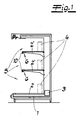
- den erfindungsgemäßen Warenpräsentationsbehälter schematisch mit der Beleuchtungseinrichtung,
- Fig. 2
- die Beleuchtungseinrichtung perspektivisch und
- Fig. 3
- einen Schnitt durch die Beleuchtungseinrichtung nach Fig. 2.
- In den Figuren ist ein Warenpräsentationsbehälter gezeigt, welcher als Kühltheke ausgeführt ist. Im Rahmen der Darstellung verfügt der Warenpräsentationsbehälter nicht einschränkend über eine Kühlwanne 1, die von einer Warenauslage 2 bzw. einem Warenboden 2 abgedeckt wird. Darüber hinaus finden sich oberhalb des Warenbodens 2 weitere Warenböden 2'.
- In oder an der Kühlwanne ist eine Kühleinrichtung 3 in Gestalt eines Kühlaggregates mit Lüfter zur Erzeugung einer die Warenauslage bzw. die Warenböden 2, 2' überströmenden Luftzirkulation. Auf den Warenböden 2, 2', sind einzelne zu kühlende Waren 4 angedeutet, die über jeweilige Entnahmeöffnungen 5 von einem Kunden aus dem Warenpräsentationsbehälter entnommen werden können. Im Bereich der jeweiligen Entnahmeöffnung 5, und zwar kopfseitig dieser Entnahmeöffnung 5, ist eine Beleuchtungseinrichtung 6 realisiert, um die auf der jeweiligen Warenauslage bzw. den Warenboden 2, 2' präsentierten Waren 4 ins rechte Licht zu setzen.
- Bei der Beleuchtungseinrichtung 6 handelt es sich im Rahmen der Erfindung um ein Leuchtengehäuse 7 mit darin angeordnetem Leuchtmittel 8. Das Leuchtmittel 8 ist als Leuchtstoffröhre auf Neonbasis ausgeführt. Dadurch können bestehende Warenpräsentationsbehälter ohne Leuchtengehäuse 7 und nur mit Leuchtmittel 8 entsprechend mit dem Leuchtengehäuse 7 nachgerüstet werden. Selbstverständlich wird von der Erfindung auch ein Leuchtmittel 8 auf LED-Basis umfasst.
- Das Leuchtengehäuse 7 ist gemäß der Darstellung nach Fig. 3 im Querschnitt im Wesentlichen dreieckförmig mit frontseitiger Transparentabdeckung 7a und rückseitigen Halteschenkeln 7b und 7c ausgebildet. Der Halteschenkel 7b übernimmt die Funktion eines Tragschenkels 7b, während der Halteschenkel 7c als Befestigungsschenkel 7c ausgeführt ist.
- Der Befestigungsschenkel 7c dient zur Halterung bzw. Aufnahme des Leuchtmittels 8 sowie einer zugehörigen Stromversorgungseinrichtung 9. Dabei ist das Leuchtmittel 8 frontseitig an den Befestigungsschenkel 7c angeschlossen, während der Befestigungsschenkel 7c rückseitig die Stromversorgungseinrichtung 9 trägt. Auf diese Weise ist die Stromversorgungseinrichtung 9 außerhalb des Leuchtengehäuses 7 angeordnet, während sich das Leuchtmittel 8 in seinem Inneren befindet. Beide Halteschenkel 7b, 7c, das heißt sowohl der Tragschenkel 7b als auch der Befestigungsschenkel 7c sind im Rahmen des Ausführungsbeispiels an das Gehäuse 1 des Warenpräsentationsbehälters angeschlossen.
- Im Detail ist dies so realisiert, dass der Tragschenkel 7b mit einem oberhalb des Warenbodens 2 angeordneten weiteren Warenboden 2' verbunden ist, während der Befestigungsschenkel 7c an eine frontseitige Blende 10 angeschlossen ist. Dadurch wird etwaige im Leuchtengehäuse 7 erzeugte Wärme unmittelbar durch Konvektion einerseits über den Tragschenkel 7b an den Warenboden 2' abgeleitet und andererseits über den Befestigungsschenkel 7c an die Blende 10 respektive ebenfalls den Warenboden 2'.
- Die frontseitige Transparentabdeckung 7a ist als Kunststoffscheibe aus PMMA mit gegebenenfalls Beschichtung ausgebildet. Dabei sorgen jeweils an die beiden Halteschenkel 7b und 7c endseitig angeformte Abkantungen 11 dafür, dass insofern eine Federhalterung für die Transparentabdeckung 7a zur Verfügung gestellt wird. Die Transparentabdeckung 7a lässt sich folglich nach vorne hin von den Abkantungen 11 entfernen, um das Leuchtmittel 8 austauschen zu können. Zur erneuten Befestigung der Transparentabdeckung 7a wird die Transparentabdeckung 7a rastend von den Abkantungen 11 hintergriffen.
- Die Halteschenkel 7b, 7c sind einteilig ausgeführt und rechtwinklig bis stumpfwinklig zueinander in L-Form angeordnet. Dabei verfügt der Tragschenkel 7b über eine größere Länge als der Befestigungsschenkel 7c, so dass als Folge dieses Umstandes und der nahezu rechtwinkligen Anordnung der beiden Halteschenkel 7b, 7c zueinander die Transparentabdeckung 7a im Vergleich zu dem Boden 2' einen spitzen Winkel α von ca. 20° bis 50°, vorzugsweise 30° bis 40°, einschließt.
- Auf diese Weise wird die vom Leuchtmittel 8 ausgehende Weißlichtstrahlung seitens der Transparentabdeckung 7a geringfügig abgelenkt und aufgefächert, so dass die auf der Warenauslage bzw. den Warenböden 2, 2' aufliegenden Waren 4 optimal über die gesamte Länge des jeweiligen Warenbodens 2, 2' ausgeleuchtet werden.
- Um die Wärmeabfuhr aus dem Leuchtengehäuse 7 noch weiter zu steigern, ist dieses seitlich offen gestaltet, so dass Kühlluft entsprechend der in Fig. 2 angedeuteten Pfeilrichtung durch das Leuchtengehäuse 7 hindurchströmen kann. Das stellt jedoch nur eine Option dar. Von besonderer Bedeutung ist noch der Umstand, dass die Stromversorgungseinrichtung 9 - außerhalb des Leuchtengehäuses 7 - einen Dimmer beinhaltet. Mit Hilfe dieses Dimmers lässt sich die dem Leuchtmittel 8 zugeführte elektrische Leistung einstellen, und zwar so wie dies eingangs bereits beschrieben worden ist.
Claims (10)
- Warenpräsentationsbehälter, insbesondere Kühltheke, mit einem Gehäuse (1) sowie einer Beleuchtungseinrichtung (6) und einer Kühleinrichtung (3), wobei die Beleuchtungseinrichtung (6) im Bereich einer Entnahmeöffnung (5) für Waren angeordnet ist, und wobei die Beleuchtungseinrichtung (6) ein Leuchtengehäuse (7) mit darin angeordnetem Leuchtmittel (8) sowie frontseitiger Transparentabdeckung (7a) und rückseitigen Halteschenkeln (7b, 7c) aufweist, dadurch gekennzeichnet, dass der eine Halteschenkel (7c) frontseitig das Leuchtmittel (8) und rückseitig eine Stromversorgungseinrichtung (9) für das Leuchtmittel (8) trägt.
- Warenpräsentationsbehälter nach Anspruch 1, dadurch gekennzeichnet, dass das Leuchtengehäuse (7) thermisch mit dem Gehäuse (1) gekoppelt ist.
- Warenpräsentationsbehälter nach Anspruch 1 oder 2, dadurch gekennzeichnet, dass das Leuchtengehäuse (7) im Querschnitt im Wesentlichen dreieckförmig mit der frontseitigen Transparentabdeckung (7a) und den rückseitigen Halteschenkeln (7b, 7c) ausgebildet ist.
- Warenpräsentationsbehälter nach Anspruch 3, dadurch gekennzeichnet, dass die Transparentabdeckung (7a) als Kunststoffscheibe aus vorzugsweise PMMA, gegebenenfalls mit Beschichtung, ausgeführt ist.
- Warenpräsentationsbehälter nach einem der Ansprüche 1 bis 4, dadurch gekennzeichnet, dass die Halteschenkel (7b, 7c) rechtwinklig bis stumpfwinklig in L-Form zueinander angeordnet sind.
- Warenpräsentationsbehälter nach einem der Ansprüche 1 bis 5, dadurch gekennzeichnet, dass der eine Halteschenkel (7c) als Befestigungsschenkel (7c) und der andere Halteschenkel (7b) als Tragschenkel (7b) ausgebildet ist.
- Warenpräsentationsbehälter nach Anspruch 6, dadurch gekennzeichnet, dass der Tragschenkel (7b) an das Gehäuse (1) angeschlossen ist.
- Warenpräsentationsbehälter nach einem der Ansprüche 1 bis 7, dadurch gekennzeichnet, dass der Befestigungsschenkel (7c) an das Gehäuse (1) angeschlossen ist.
- Warenpräsentationsbehälter nach Anspruch 1 bis 8, dadurch gekennzeichnet, dass die Stromversorgungseinrichtung (9) wenigstens einen Dimmer beinhaltet, um die dem Leuchtmittel (8) zugeführte elektrische Leistung einstellen zu können.
- Warenpräsentationsbehälter nach einem der Ansprüche 1 bis 9, dadurch gekennzeichnet, dass die Beleuchtungseinrichtung (6) verdeckt hinter einer Blende (10) angebracht ist.
Applications Claiming Priority (1)
| Application Number | Priority Date | Filing Date | Title |
|---|---|---|---|
| DE102004040120A DE102004040120A1 (de) | 2004-08-18 | 2004-08-18 | Warenpräsentationsbehälter, insbesondere Kühltheke |
Publications (2)
| Publication Number | Publication Date |
|---|---|
| EP1627584A1 true EP1627584A1 (de) | 2006-02-22 |
| EP1627584B1 EP1627584B1 (de) | 2011-04-20 |
Family
ID=34936798
Family Applications (1)
| Application Number | Title | Priority Date | Filing Date |
|---|---|---|---|
| EP05011053A Expired - Lifetime EP1627584B1 (de) | 2004-08-18 | 2005-05-21 | Warenpräsentationsbehälter, insbesondere Kühltheke |
Country Status (4)
| Country | Link |
|---|---|
| EP (1) | EP1627584B1 (de) |
| AT (1) | ATE505981T1 (de) |
| AU (1) | AU2005203136B2 (de) |
| DE (2) | DE102004040120A1 (de) |
Cited By (5)
| Publication number | Priority date | Publication date | Assignee | Title |
|---|---|---|---|---|
| EP1922958A1 (de) | 2006-11-16 | 2008-05-21 | Aldi Einkauf GmbH & Co.oHG | Aggregat aus Warenpräsentationsmöbel und Kühleinrichtung |
| EP1961341A1 (de) * | 2007-02-26 | 2008-08-27 | Sanyo Electric Co., Ltd. | Schaukasten |
| DE102007053545A1 (de) * | 2007-11-07 | 2009-04-09 | Schott Ag | Kühlgerät mit LED-Beleuchtung |
| EP2218362A1 (de) | 2009-02-16 | 2010-08-18 | Aldi Einkauf GmbH & Co. oHG | Warenpräsentationsbehälter |
| EP2092862A3 (de) * | 2008-02-19 | 2012-10-10 | Sanyo Electric Co., Ltd. | Schaukasten |
Citations (4)
| Publication number | Priority date | Publication date | Assignee | Title |
|---|---|---|---|---|
| US2308726A (en) | 1940-12-24 | 1943-01-19 | Seeger Refrigerator Co | Two-way lighting device for refrigerators |
| US4977754A (en) * | 1990-05-01 | 1990-12-18 | Specialty Equipment Companies, Inc. | Next-to-be-purchased cold beverage merchandiser |
| JPH03159612A (ja) | 1989-11-17 | 1991-07-09 | Sanyo Electric Co Ltd | 棚装置 |
| DE9318421U1 (de) | 1993-12-02 | 1994-10-13 | akf - Allgemeine Kühlmöbelbau GmbH & Co. KG, 86165 Augsburg | Verkaufstheke |
Family Cites Families (1)
| Publication number | Priority date | Publication date | Assignee | Title |
|---|---|---|---|---|
| AU628709B2 (en) * | 1990-02-06 | 1992-09-17 | John Walter Ferguson | Illuminated cabinets |
-
2004
- 2004-08-18 DE DE102004040120A patent/DE102004040120A1/de not_active Withdrawn
-
2005
- 2005-05-21 EP EP05011053A patent/EP1627584B1/de not_active Expired - Lifetime
- 2005-05-21 AT AT05011053T patent/ATE505981T1/de active
- 2005-05-21 DE DE502005011267T patent/DE502005011267D1/de not_active Expired - Lifetime
- 2005-07-19 AU AU2005203136A patent/AU2005203136B2/en not_active Ceased
Patent Citations (4)
| Publication number | Priority date | Publication date | Assignee | Title |
|---|---|---|---|---|
| US2308726A (en) | 1940-12-24 | 1943-01-19 | Seeger Refrigerator Co | Two-way lighting device for refrigerators |
| JPH03159612A (ja) | 1989-11-17 | 1991-07-09 | Sanyo Electric Co Ltd | 棚装置 |
| US4977754A (en) * | 1990-05-01 | 1990-12-18 | Specialty Equipment Companies, Inc. | Next-to-be-purchased cold beverage merchandiser |
| DE9318421U1 (de) | 1993-12-02 | 1994-10-13 | akf - Allgemeine Kühlmöbelbau GmbH & Co. KG, 86165 Augsburg | Verkaufstheke |
Cited By (6)
| Publication number | Priority date | Publication date | Assignee | Title |
|---|---|---|---|---|
| EP1922958A1 (de) | 2006-11-16 | 2008-05-21 | Aldi Einkauf GmbH & Co.oHG | Aggregat aus Warenpräsentationsmöbel und Kühleinrichtung |
| EP1961341A1 (de) * | 2007-02-26 | 2008-08-27 | Sanyo Electric Co., Ltd. | Schaukasten |
| US7726831B2 (en) | 2007-02-26 | 2010-06-01 | Sanyo Electric Co., Ltd. | Showcase |
| DE102007053545A1 (de) * | 2007-11-07 | 2009-04-09 | Schott Ag | Kühlgerät mit LED-Beleuchtung |
| EP2092862A3 (de) * | 2008-02-19 | 2012-10-10 | Sanyo Electric Co., Ltd. | Schaukasten |
| EP2218362A1 (de) | 2009-02-16 | 2010-08-18 | Aldi Einkauf GmbH & Co. oHG | Warenpräsentationsbehälter |
Also Published As
| Publication number | Publication date |
|---|---|
| DE102004040120A1 (de) | 2006-02-23 |
| AU2005203136B2 (en) | 2011-06-30 |
| ATE505981T1 (de) | 2011-05-15 |
| AU2005203136A1 (en) | 2006-03-09 |
| DE502005011267D1 (de) | 2011-06-01 |
| EP1627584B1 (de) | 2011-04-20 |
Similar Documents
| Publication | Publication Date | Title |
|---|---|---|
| EP2251588B1 (de) | Lampe für hausgerät sowie hausgerät, insbesondere zum zubereiten von lebensmitteln, mit einer lampe | |
| US9615676B2 (en) | Product display case or hot plate display case having an edge-mounted LED array for illuminating a light pipe for illuminating the interior portion of the product display case or hot plate display case, and/or an edge mounted LED array for illuminating a glass shelf within the product display case or hot plate display case | |
| EP2421414B1 (de) | Led-beleuchtung für gekühlte verkaufsmöbel | |
| EP2092860A2 (de) | Schaukasten | |
| DE102007053545A1 (de) | Kühlgerät mit LED-Beleuchtung | |
| EP2602553B1 (de) | Haushaltsgerätetür mit Beleuchtungseinrichtung | |
| EP1627584B1 (de) | Warenpräsentationsbehälter, insbesondere Kühltheke | |
| EP0446692A1 (de) | Beleuchtungsvorrichtung mit Lichtleitern, insbesondere für Kühlräume und explosionsgeschützte Räume | |
| DE102014203530B4 (de) | Beleuchtungsvorrichtung zum Ausleuchten eines Garraums eines Gargeräts sowie Gargerät mit einer Beleuchtungsvorrichtung | |
| DE102007021574A1 (de) | Haushaltskältegerät | |
| DE102014203531A1 (de) | Gargerät mit einer spezifischen Kühlung einer Beleuchtungsvorrichtung | |
| DE102012207851B4 (de) | Dunstabzugshaube mit Beleuchtungseinheit | |
| EP1627583B1 (de) | Warenpräsentationsbehälter, insbesondere Kühltheke | |
| DE102018002685A1 (de) | Ablageboden mit Beleuchtungsfunktion für ein Haushalts-Kühlgerät | |
| DE102007004702A1 (de) | Fahrzeugleuchte mit einer Betauungsschutzeinrichtung | |
| DE202008003928U1 (de) | Licht-Wärme-Strahler | |
| EP1956325A2 (de) | Kühl- und/oder Gefriergerät | |
| DE102011001113B4 (de) | Leuchte | |
| EP2251590A1 (de) | Verfahren zum Austausch einer Leuchtstoffröhre sowie Reflektor zur Durchführung dieses Verfahrens | |
| EP3861892A1 (de) | Leuchte zum ausleuchten von regalmöbeln und regalmöbel mit einer leuchte | |
| EP2708838A2 (de) | Beleuchtungskonzept für Kühlmöbel | |
| EP2300761A1 (de) | Tiefkühlmöbel | |
| DE10311876A1 (de) | Regalvorsatzleuchte | |
| US20250064227A1 (en) | Accessory bracket and display cabinet | |
| DE102010063747A1 (de) | Dunstabzugshaube mit Leuchtmodul |
Legal Events
| Date | Code | Title | Description |
|---|---|---|---|
| PUAI | Public reference made under article 153(3) epc to a published international application that has entered the european phase |
Free format text: ORIGINAL CODE: 0009012 |
|
| AK | Designated contracting states |
Kind code of ref document: A1 Designated state(s): AT BE BG CH CY CZ DE DK EE ES FI FR GB GR HU IE IS IT LI LT LU MC NL PL PT RO SE SI SK TR |
|
| AX | Request for extension of the european patent |
Extension state: AL BA HR LV MK YU |
|
| 17P | Request for examination filed |
Effective date: 20060623 |
|
| AKX | Designation fees paid |
Designated state(s): AT BE BG CH CY CZ DE DK EE ES FI FR GB GR HU IE IS IT LI LT LU MC NL PL PT RO SE SI SK TR |
|
| AXX | Extension fees paid |
Extension state: HR Payment date: 20060623 |
|
| 17Q | First examination report despatched |
Effective date: 20070725 |
|
| GRAP | Despatch of communication of intention to grant a patent |
Free format text: ORIGINAL CODE: EPIDOSNIGR1 |
|
| GRAS | Grant fee paid |
Free format text: ORIGINAL CODE: EPIDOSNIGR3 |
|
| GRAA | (expected) grant |
Free format text: ORIGINAL CODE: 0009210 |
|
| AK | Designated contracting states |
Kind code of ref document: B1 Designated state(s): AT BE BG CH CY CZ DE DK EE ES FI FR GB GR HU IE IS IT LI LT LU MC NL PL PT RO SE SI SK TR |
|
| AX | Request for extension of the european patent |
Extension state: HR |
|
| REG | Reference to a national code |
Ref country code: GB Ref legal event code: FG4D Free format text: NOT ENGLISH |
|
| REG | Reference to a national code |
Ref country code: CH Ref legal event code: EP |
|
| REG | Reference to a national code |
Ref country code: IE Ref legal event code: FG4D Free format text: LANGUAGE OF EP DOCUMENT: GERMAN |
|
| REF | Corresponds to: |
Ref document number: 502005011267 Country of ref document: DE Date of ref document: 20110601 Kind code of ref document: P |
|
| REG | Reference to a national code |
Ref country code: DE Ref legal event code: R096 Ref document number: 502005011267 Country of ref document: DE Effective date: 20110601 |
|
| REG | Reference to a national code |
Ref country code: NL Ref legal event code: VDEP Effective date: 20110420 |
|
| LTIE | Lt: invalidation of european patent or patent extension |
Effective date: 20110420 |
|
| PG25 | Lapsed in a contracting state [announced via postgrant information from national office to epo] |
Ref country code: SE Free format text: LAPSE BECAUSE OF FAILURE TO SUBMIT A TRANSLATION OF THE DESCRIPTION OR TO PAY THE FEE WITHIN THE PRESCRIBED TIME-LIMIT Effective date: 20110420 Ref country code: PT Free format text: LAPSE BECAUSE OF FAILURE TO SUBMIT A TRANSLATION OF THE DESCRIPTION OR TO PAY THE FEE WITHIN THE PRESCRIBED TIME-LIMIT Effective date: 20110822 Ref country code: LT Free format text: LAPSE BECAUSE OF FAILURE TO SUBMIT A TRANSLATION OF THE DESCRIPTION OR TO PAY THE FEE WITHIN THE PRESCRIBED TIME-LIMIT Effective date: 20110420 |
|
| REG | Reference to a national code |
Ref country code: IE Ref legal event code: FD4D |
|
| BERE | Be: lapsed |
Owner name: ALDI EINKAUF G.M.B.H. & CO. OHG Effective date: 20110531 |
|
| PG25 | Lapsed in a contracting state [announced via postgrant information from national office to epo] |
Ref country code: ES Free format text: LAPSE BECAUSE OF FAILURE TO SUBMIT A TRANSLATION OF THE DESCRIPTION OR TO PAY THE FEE WITHIN THE PRESCRIBED TIME-LIMIT Effective date: 20110731 Ref country code: SI Free format text: LAPSE BECAUSE OF FAILURE TO SUBMIT A TRANSLATION OF THE DESCRIPTION OR TO PAY THE FEE WITHIN THE PRESCRIBED TIME-LIMIT Effective date: 20110420 Ref country code: CY Free format text: LAPSE BECAUSE OF FAILURE TO SUBMIT A TRANSLATION OF THE DESCRIPTION OR TO PAY THE FEE WITHIN THE PRESCRIBED TIME-LIMIT Effective date: 20110420 Ref country code: IS Free format text: LAPSE BECAUSE OF FAILURE TO SUBMIT A TRANSLATION OF THE DESCRIPTION OR TO PAY THE FEE WITHIN THE PRESCRIBED TIME-LIMIT Effective date: 20110820 Ref country code: FI Free format text: LAPSE BECAUSE OF FAILURE TO SUBMIT A TRANSLATION OF THE DESCRIPTION OR TO PAY THE FEE WITHIN THE PRESCRIBED TIME-LIMIT Effective date: 20110420 Ref country code: GR Free format text: LAPSE BECAUSE OF FAILURE TO SUBMIT A TRANSLATION OF THE DESCRIPTION OR TO PAY THE FEE WITHIN THE PRESCRIBED TIME-LIMIT Effective date: 20110721 |
|
| PG25 | Lapsed in a contracting state [announced via postgrant information from national office to epo] |
Ref country code: NL Free format text: LAPSE BECAUSE OF FAILURE TO SUBMIT A TRANSLATION OF THE DESCRIPTION OR TO PAY THE FEE WITHIN THE PRESCRIBED TIME-LIMIT Effective date: 20110420 Ref country code: MC Free format text: LAPSE BECAUSE OF NON-PAYMENT OF DUE FEES Effective date: 20110531 |
|
| REG | Reference to a national code |
Ref country code: CH Ref legal event code: PL |
|
| PG25 | Lapsed in a contracting state [announced via postgrant information from national office to epo] |
Ref country code: IE Free format text: LAPSE BECAUSE OF FAILURE TO SUBMIT A TRANSLATION OF THE DESCRIPTION OR TO PAY THE FEE WITHIN THE PRESCRIBED TIME-LIMIT Effective date: 20110420 Ref country code: CH Free format text: LAPSE BECAUSE OF NON-PAYMENT OF DUE FEES Effective date: 20110531 Ref country code: LI Free format text: LAPSE BECAUSE OF NON-PAYMENT OF DUE FEES Effective date: 20110531 Ref country code: CZ Free format text: LAPSE BECAUSE OF FAILURE TO SUBMIT A TRANSLATION OF THE DESCRIPTION OR TO PAY THE FEE WITHIN THE PRESCRIBED TIME-LIMIT Effective date: 20110420 Ref country code: EE Free format text: LAPSE BECAUSE OF FAILURE TO SUBMIT A TRANSLATION OF THE DESCRIPTION OR TO PAY THE FEE WITHIN THE PRESCRIBED TIME-LIMIT Effective date: 20110420 |
|
| PLBE | No opposition filed within time limit |
Free format text: ORIGINAL CODE: 0009261 |
|
| STAA | Information on the status of an ep patent application or granted ep patent |
Free format text: STATUS: NO OPPOSITION FILED WITHIN TIME LIMIT |
|
| PG25 | Lapsed in a contracting state [announced via postgrant information from national office to epo] |
Ref country code: RO Free format text: LAPSE BECAUSE OF FAILURE TO SUBMIT A TRANSLATION OF THE DESCRIPTION OR TO PAY THE FEE WITHIN THE PRESCRIBED TIME-LIMIT Effective date: 20110420 Ref country code: DK Free format text: LAPSE BECAUSE OF FAILURE TO SUBMIT A TRANSLATION OF THE DESCRIPTION OR TO PAY THE FEE WITHIN THE PRESCRIBED TIME-LIMIT Effective date: 20110420 Ref country code: PL Free format text: LAPSE BECAUSE OF FAILURE TO SUBMIT A TRANSLATION OF THE DESCRIPTION OR TO PAY THE FEE WITHIN THE PRESCRIBED TIME-LIMIT Effective date: 20110420 Ref country code: SK Free format text: LAPSE BECAUSE OF FAILURE TO SUBMIT A TRANSLATION OF THE DESCRIPTION OR TO PAY THE FEE WITHIN THE PRESCRIBED TIME-LIMIT Effective date: 20110420 |
|
| REG | Reference to a national code |
Ref country code: FR Ref legal event code: ST Effective date: 20120217 |
|
| 26N | No opposition filed |
Effective date: 20120123 |
|
| GBPC | Gb: european patent ceased through non-payment of renewal fee |
Effective date: 20110720 |
|
| PG25 | Lapsed in a contracting state [announced via postgrant information from national office to epo] |
Ref country code: BE Free format text: LAPSE BECAUSE OF NON-PAYMENT OF DUE FEES Effective date: 20110531 |
|
| PG25 | Lapsed in a contracting state [announced via postgrant information from national office to epo] |
Ref country code: FR Free format text: LAPSE BECAUSE OF NON-PAYMENT OF DUE FEES Effective date: 20110620 |
|
| REG | Reference to a national code |
Ref country code: DE Ref legal event code: R097 Ref document number: 502005011267 Country of ref document: DE Effective date: 20120123 |
|
| PG25 | Lapsed in a contracting state [announced via postgrant information from national office to epo] |
Ref country code: IT Free format text: LAPSE BECAUSE OF FAILURE TO SUBMIT A TRANSLATION OF THE DESCRIPTION OR TO PAY THE FEE WITHIN THE PRESCRIBED TIME-LIMIT Effective date: 20110420 |
|
| PG25 | Lapsed in a contracting state [announced via postgrant information from national office to epo] |
Ref country code: GB Free format text: LAPSE BECAUSE OF NON-PAYMENT OF DUE FEES Effective date: 20110720 |
|
| REG | Reference to a national code |
Ref country code: AT Ref legal event code: MM01 Ref document number: 505981 Country of ref document: AT Kind code of ref document: T Effective date: 20110521 |
|
| PG25 | Lapsed in a contracting state [announced via postgrant information from national office to epo] |
Ref country code: LU Free format text: LAPSE BECAUSE OF NON-PAYMENT OF DUE FEES Effective date: 20110521 |
|
| PG25 | Lapsed in a contracting state [announced via postgrant information from national office to epo] |
Ref country code: BG Free format text: LAPSE BECAUSE OF FAILURE TO SUBMIT A TRANSLATION OF THE DESCRIPTION OR TO PAY THE FEE WITHIN THE PRESCRIBED TIME-LIMIT Effective date: 20110720 |
|
| PG25 | Lapsed in a contracting state [announced via postgrant information from national office to epo] |
Ref country code: TR Free format text: LAPSE BECAUSE OF FAILURE TO SUBMIT A TRANSLATION OF THE DESCRIPTION OR TO PAY THE FEE WITHIN THE PRESCRIBED TIME-LIMIT Effective date: 20110420 |
|
| PG25 | Lapsed in a contracting state [announced via postgrant information from national office to epo] |
Ref country code: HU Free format text: LAPSE BECAUSE OF FAILURE TO SUBMIT A TRANSLATION OF THE DESCRIPTION OR TO PAY THE FEE WITHIN THE PRESCRIBED TIME-LIMIT Effective date: 20110420 |
|
| PG25 | Lapsed in a contracting state [announced via postgrant information from national office to epo] |
Ref country code: AT Free format text: LAPSE BECAUSE OF NON-PAYMENT OF DUE FEES Effective date: 20110521 |
|
| REG | Reference to a national code |
Ref country code: DE Ref legal event code: R082 Ref document number: 502005011267 Country of ref document: DE Representative=s name: ANDREJEWSKI HONKE PATENT- UND RECHTSANWAELTE P, DE Ref country code: DE Ref legal event code: R081 Ref document number: 502005011267 Country of ref document: DE Owner name: ALDI SUED DIENSTLEISTUNGS-GMBH & CO. OHG, DE Free format text: FORMER OWNER: ALDI EINKAUF GMBH & CO. OHG, 45476 MUELHEIM, DE Ref country code: DE Ref legal event code: R082 Ref document number: 502005011267 Country of ref document: DE Representative=s name: ANDREJEWSKI - HONKE PATENT- UND RECHTSANWAELTE, DE |
|
| PGFP | Annual fee paid to national office [announced via postgrant information from national office to epo] |
Ref country code: DE Payment date: 20180511 Year of fee payment: 14 |
|
| REG | Reference to a national code |
Ref country code: DE Ref legal event code: R119 Ref document number: 502005011267 Country of ref document: DE |
|
| PG25 | Lapsed in a contracting state [announced via postgrant information from national office to epo] |
Ref country code: DE Free format text: LAPSE BECAUSE OF NON-PAYMENT OF DUE FEES Effective date: 20191203 |