EP1627812A2 - An engine mounting assembly - Google Patents
An engine mounting assembly Download PDFInfo
- Publication number
- EP1627812A2 EP1627812A2 EP05254597A EP05254597A EP1627812A2 EP 1627812 A2 EP1627812 A2 EP 1627812A2 EP 05254597 A EP05254597 A EP 05254597A EP 05254597 A EP05254597 A EP 05254597A EP 1627812 A2 EP1627812 A2 EP 1627812A2
- Authority
- EP
- European Patent Office
- Prior art keywords
- engine
- mounting assembly
- assembly according
- assembly
- load absorbing
- Prior art date
- Legal status (The legal status is an assumption and is not a legal conclusion. Google has not performed a legal analysis and makes no representation as to the accuracy of the status listed.)
- Granted
Links
- 230000003019 stabilising effect Effects 0.000 claims abstract description 19
- 230000000712 assembly Effects 0.000 claims description 15
- 238000000429 assembly Methods 0.000 claims description 15
- 239000007789 gas Substances 0.000 description 10
- 238000000034 method Methods 0.000 description 2
- 230000001141 propulsive effect Effects 0.000 description 2
- 241001669573 Galeorhinus galeus Species 0.000 description 1
- 230000000694 effects Effects 0.000 description 1
- 238000012423 maintenance Methods 0.000 description 1
- 238000012986 modification Methods 0.000 description 1
- 230000004048 modification Effects 0.000 description 1
Images


Classifications
-
- B—PERFORMING OPERATIONS; TRANSPORTING
- B64—AIRCRAFT; AVIATION; COSMONAUTICS
- B64D—EQUIPMENT FOR FITTING IN OR TO AIRCRAFT; FLIGHT SUITS; PARACHUTES; ARRANGEMENT OR MOUNTING OF POWER PLANTS OR PROPULSION TRANSMISSIONS IN AIRCRAFT
- B64D27/00—Arrangement or mounting of power plants in aircraft; Aircraft characterised by the type or position of power plants
- B64D27/02—Aircraft characterised by the type or position of power plants
- B64D27/16—Aircraft characterised by the type or position of power plants of jet type
- B64D27/20—Aircraft characterised by the type or position of power plants of jet type within, or attached to, fuselages
-
- B—PERFORMING OPERATIONS; TRANSPORTING
- B64—AIRCRAFT; AVIATION; COSMONAUTICS
- B64D—EQUIPMENT FOR FITTING IN OR TO AIRCRAFT; FLIGHT SUITS; PARACHUTES; ARRANGEMENT OR MOUNTING OF POWER PLANTS OR PROPULSION TRANSMISSIONS IN AIRCRAFT
- B64D27/00—Arrangement or mounting of power plants in aircraft; Aircraft characterised by the type or position of power plants
- B64D27/40—Arrangements for mounting power plants in aircraft
- B64D27/402—Arrangements for mounting power plants in aircraft comprising box like supporting frames, e.g. pylons or arrangements for embracing the power plant
-
- B—PERFORMING OPERATIONS; TRANSPORTING
- B64—AIRCRAFT; AVIATION; COSMONAUTICS
- B64D—EQUIPMENT FOR FITTING IN OR TO AIRCRAFT; FLIGHT SUITS; PARACHUTES; ARRANGEMENT OR MOUNTING OF POWER PLANTS OR PROPULSION TRANSMISSIONS IN AIRCRAFT
- B64D27/00—Arrangement or mounting of power plants in aircraft; Aircraft characterised by the type or position of power plants
- B64D27/40—Arrangements for mounting power plants in aircraft
- B64D27/404—Suspension arrangements specially adapted for supporting vertical loads
-
- F—MECHANICAL ENGINEERING; LIGHTING; HEATING; WEAPONS; BLASTING
- F02—COMBUSTION ENGINES; HOT-GAS OR COMBUSTION-PRODUCT ENGINE PLANTS
- F02C—GAS-TURBINE PLANTS; AIR INTAKES FOR JET-PROPULSION PLANTS; CONTROLLING FUEL SUPPLY IN AIR-BREATHING JET-PROPULSION PLANTS
- F02C7/00—Features, components parts, details or accessories, not provided for in, or of interest apart form groups F02C1/00 - F02C6/00; Air intakes for jet-propulsion plants
- F02C7/20—Mounting or supporting of plant; Accommodating heat expansion or creep
-
- F—MECHANICAL ENGINEERING; LIGHTING; HEATING; WEAPONS; BLASTING
- F02—COMBUSTION ENGINES; HOT-GAS OR COMBUSTION-PRODUCT ENGINE PLANTS
- F02C—GAS-TURBINE PLANTS; AIR INTAKES FOR JET-PROPULSION PLANTS; CONTROLLING FUEL SUPPLY IN AIR-BREATHING JET-PROPULSION PLANTS
- F02C7/00—Features, components parts, details or accessories, not provided for in, or of interest apart form groups F02C1/00 - F02C6/00; Air intakes for jet-propulsion plants
- F02C7/32—Arrangement, mounting, or driving, of auxiliaries
-
- Y—GENERAL TAGGING OF NEW TECHNOLOGICAL DEVELOPMENTS; GENERAL TAGGING OF CROSS-SECTIONAL TECHNOLOGIES SPANNING OVER SEVERAL SECTIONS OF THE IPC; TECHNICAL SUBJECTS COVERED BY FORMER USPC CROSS-REFERENCE ART COLLECTIONS [XRACs] AND DIGESTS
- Y02—TECHNOLOGIES OR APPLICATIONS FOR MITIGATION OR ADAPTATION AGAINST CLIMATE CHANGE
- Y02T—CLIMATE CHANGE MITIGATION TECHNOLOGIES RELATED TO TRANSPORTATION
- Y02T50/00—Aeronautics or air transport
- Y02T50/60—Efficient propulsion technologies, e.g. for aircraft
Definitions
- This invention relates to engine mounting assemblies. More particularly but not exclusively, the invention relates to engine mounting assemblies for gas turbine engines.
- a gas turbine engine can be mounted onto an aircraft.
- One way is by the use of an integrated mount and pylon concept which requires a three node frame at the rear of the engine.
- an open framed structure is provided and the engine is cantilevered forward from a bulkhead on the aircraft.
- a third method is the use of a structural by-pass duct and rear mount ring.
- an engine mounting assembly for an engine comprising a plurality of carrying arrangements, each carrying arrangement comprising a rear load absorbing assembly mountable on the engine, each rear load absorbing assembly providing a rear mounting point for an engine carrier, and each carrying arrangement further comprising first and second stabilising members extending forwardly from the said rear mounting point of the rear load absorbing assembly to first and second spaced forward mounting points for an engine carrier.
- each carrying arrangement comprises a frame.
- the engine is preferably a gas turbine engine.
- each rear load absorbing assembly comprises a plurality of rear members.
- the rear members may be coupled to each other to provide a load absorbing configuration.
- the coupled rear members may comprise an A-frame.
- the rear load absorbing assembly comprises a pair of rear members configured to form an A-frame.
- Each rear member preferably comprises a rear strut.
- The, or each, rear mounting point may be provided at the apex of the, or each, aforesaid A-frame.
- The, or each, A-frame may lean axially of the engine. In one embodiment, such axial leaning can be viewed from the side or the top.
- the plurality of carrying arrangements are arranged adjacent each other, conveniently circumferentially around the engine.
- at least one stabilising member of each carrying arrangement is coupled to a stabilising member of one of the adjacent carrying arrangements, to provide one of said forward mounting points.
- each stabilising member of each carrying arrangement is coupled to a stabilising member of adjacent carrying arrangements to provide said forward mounting points.
- each stabilising member comprises a stabilising strut.
- each rear load absorbing assembly may be mountable on the engine core casing.
- Each forward mounting point may be provided at the fan case of the engine.
- the engine mounting assembly may further include a front mount beam to which the carrier can be connected.
- the front mount beam may extend between two adjacent forward mounting points.
- the engine mounting assembly may comprise up to eight rear load absorbing assemblies.
- the engine mounting assembly comprises no less than three rear load absorbing assemblies.
- the engine mounting assembly comprises four rear load absorbing assemblies.
- the rear load absorbing assemblies are preferably substantially equispaced around the engine.
- the rear load absorbing assemblies are provided substantially at top dead centre and/or bottom dead centre and/or on the horizontal centre line left of the engine and/or on the horizontal centre line at the right of the engine.
- the engine mounting assembly may comprise up to eight forward mounting points.
- the engine mounting assembly comprises no less than three forward mounting points.
- the engine mounting assembly comprises four forward mounting points. Forward mounting points are preferably substantially equispaced around the engine.
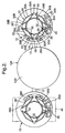
- FIG. 1 there is shown a gas turbine engine 10 attached to a carrier in the form of a pylon 12, the pylon 12 being used to mount the engine on an aircraft 12A.
- the gas turbine engine 10 is a standard gas turbine engine comprising a fan (not shown) for providing propulsive thrust.
- the engine also includes compressors (not shown), a combustor assembly, and turbines. Air from the fan is split into two flows. A first outer annular flow for providing the propulsive thrust, and a second inner annular flow which passes through the compressors, combustor assembly and turbines.
- the fan is surrounded by a fan casing 14, and the compressors, combustor assembly and turbines are surrounded by a core casing 16.
- an engine mounting assembly 20 is provided.
- the engine mounting assembly 20 comprises a plurality of carrying arrangements 22.
- Each carrying arrangement 22 comprises a rear load absorbing assembly 24 for absorbing thrust, lateral and vertical loads on the engine.
- Each load absorbing assembly 24, provides a rear mounting point 26.
- the rear load absorbing assemblies 24 are circumferentially arranged around the engine towards the rear thereof and are mounted to the core casing 16.
- Each carrying arrangement 22 is in the form of a frame and comprises first and second forwardly extending stabilising struts 28A, 28B which extend forwardly from the rear mounting points 26 to the fan casing 14.
- the stabilising strut 28A on one of the carrying arrangements 22 is connected to the stabilising strut 28B of the adjacent carrying arrangement 22 at the fan casing to provide a plurality of forward mounting points 29.
- the preferred embodiment provides the advantages that the thrust loads are spread from the rear mounting points 26, via the first and second forwardly extending stabilising struts to the forward mounting points 29. This minimises local loading and distortion of the fan case.
- the forward mounting points 29 combine to absorb roll, lateral and vertical loads on the engine. In combination with the rear mounting points 26, the engine is thus mounted in a statically determinate manner.
- Each of the rear load absorbing assemblies 24 comprises first and second rear struts 30A, 30B extending outwardly from each other to the core casing 16 to provide an A-frame arrangement 32.
- first and second rear struts 30A, 30B span the engine fan stream flow and are aerodynamically shaped to minimise losses.
- a front beam mount 34 is provided which connects to the fan casing 14, which, in turn, is connected to the forward mounting points 29
- the pylon 12 extends rearwardly of the engine 10 to be connected to one of the rear mounting points 26 in line therewith.
- FIG. 2 there is shown a pair of the engines 10 mounted opposite each other about the fuselage 12B of the aircraft 12A by respective pylons 12.
- FIG. 3 there is shown an engine 10 which is mounted under the wing of an aircraft.
- the engine 10 in Fig.3 comprises all the same features as shown in Figs. 1 and 2, and these have been designated with the same reference numeral.
- the engine 10 shown in Fig. 3 is mounted to the underside of the wing 38 in the same way that the engines 10 are mounted to the fuselage 12B of the aircraft 12A in Figs. 1 and 2.
- the engine 10 is shown connected to the mounting points at the tope dead centre of the engine 10.
- FIG. 4 there is shown an engine 10 mounted over the wing 38 in the same way as the engine 10 is mounted under the wing 38 in Fig. 3, and to the fuselage in Figs. 1 and 2.
- the engine 10 is shown connected to the mounting points at bottom dead centre of the engine 10.
- FIG. 5 there is shown another way in which the engine 10 can be mounted over a wing, this time at the front mounting point 26 at the respective right and left hand sides of the engine 10).
- a pylon 112 extends from the front beam mount and the rear mounting point 26 downwardly to the wing 38. This embodiment has the advantage that it avoids a clash in the amount of space available for the front mountbeam 34 and the gearbox.
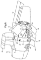
- Fig.6 shows a drawing similar to Fig. 1, but in which the engine 10 is provided with an aerodynamic nacelle fairing or pod 40, surrounding an engine core 41.
- the nacelle 40 comprises a fixed part 43 and a pair of diametrically opposed thrust reverser doors 44.
- the nacelle 40 is shown with cowl doors 42 open to provide access to the internals of the engine.
- the thrust reverser doors 44 are shown in an open condition, i.e. the position in which they are in during thrust reversal to slow down the aircraft on landing.
- the thrust reverser doors 44 are also shown in the open condition in broken lines in Figs. 2, 3, 4 and 5.
- the thrust reverser doors 44 are movable from a closed position to an open position. In the closed position, the thrust reverser doors lie substantially flush with the fixed part 43 of the nacelle 40, and allow the thrust gases from the engine 10 to be directed rearwardly of the engine 10, thereby driving the aeroplane in a forward direction.
- each of the thrust reverser doors 44 lie in the path of the thrust gases, thereby directing the thrust gases forwardly of the engine 10 to slow down the aeroplane, for example after landing.
- the thrust reverser doors 44 are arranged over the engine core 41. This provides the advantages in the preferred embodiment of allowing access to the engine core 41, for example for maintenance purposes.
- the number of carrying arrangements, 22 can be up to eight or as few as three.
- the loud carrying members could be integrated with, or separate to, the nacelle components.
Landscapes
- Engineering & Computer Science (AREA)
- Chemical & Material Sciences (AREA)
- Combustion & Propulsion (AREA)
- Aviation & Aerospace Engineering (AREA)
- Mechanical Engineering (AREA)
- General Engineering & Computer Science (AREA)
- Structures Of Non-Positive Displacement Pumps (AREA)
- Filling Or Discharging Of Gas Storage Vessels (AREA)
Abstract
Description
- This invention relates to engine mounting assemblies. More particularly but not exclusively, the invention relates to engine mounting assemblies for gas turbine engines.
- There are several ways in which a gas turbine engine can be mounted onto an aircraft. One way is by the use of an integrated mount and pylon concept which requires a three node frame at the rear of the engine. In another method, an open framed structure is provided and the engine is cantilevered forward from a bulkhead on the aircraft. A third method is the use of a structural by-pass duct and rear mount ring.
- According to one aspect of this invention, there is provided an engine mounting assembly for an engine, said engine mounting assembly comprising a plurality of carrying arrangements, each carrying arrangement comprising a rear load absorbing assembly mountable on the engine, each rear load absorbing assembly providing a rear mounting point for an engine carrier, and each carrying arrangement further comprising first and second stabilising members extending forwardly from the said rear mounting point of the rear load absorbing assembly to first and second spaced forward mounting points for an engine carrier.
- Preferably, the spaced forward mounting points are circumferentially spaced from each other. Conveniently, each carrying arrangement comprises a frame.
- The engine is preferably a gas turbine engine.
- Preferably, each rear load absorbing assembly comprises a plurality of rear members. The rear members may be coupled to each other to provide a load absorbing configuration. The coupled rear members may comprise an A-frame. Preferably, the rear load absorbing assembly comprises a pair of rear members configured to form an A-frame. Each rear member preferably comprises a rear strut.
- The, or each, rear mounting point may be provided at the apex of the, or each, aforesaid A-frame. The, or each, A-frame may lean axially of the engine. In one embodiment, such axial leaning can be viewed from the side or the top.
- Conveniently, the plurality of carrying arrangements are arranged adjacent each other, conveniently circumferentially around the engine. In one embodiment, at least one stabilising member of each carrying arrangement is coupled to a stabilising member of one of the adjacent carrying arrangements, to provide one of said forward mounting points. Preferably, each stabilising member of each carrying arrangement is coupled to a stabilising member of adjacent carrying arrangements to provide said forward mounting points. Preferably, each stabilising member comprises a stabilising strut.
- Preferably each rear load absorbing assembly may be mountable on the engine core casing. Each forward mounting point may be provided at the fan case of the engine.
- The engine mounting assembly may further include a front mount beam to which the carrier can be connected. The front mount beam may extend between two adjacent forward mounting points.
- The engine mounting assembly may comprise up to eight rear load absorbing assemblies. Preferably, the engine mounting assembly comprises no less than three rear load absorbing assemblies. In the preferred embodiment, the engine mounting assembly comprises four rear load absorbing assemblies. The rear load absorbing assemblies are preferably substantially equispaced around the engine.
- Preferably, the rear load absorbing assemblies are provided substantially at top dead centre and/or bottom dead centre and/or on the horizontal centre line left of the engine and/or on the horizontal centre line at the right of the engine.
- The engine mounting assembly may comprise up to eight forward mounting points. Preferably, the engine mounting assembly comprises no less than three forward mounting points. In the preferred embodiment, the engine mounting assembly comprises four forward mounting points. Forward mounting points are preferably substantially equispaced around the engine.
- An embodiment of the invention will now be described by way of example only, with reference to the accompanying drawings, in which:
- Fig. 1 is a perspective view of a gas turbine engine mounted to an aircraft by a pylon, in which the outer casing of the engine has been removed.
- Fig. 2 is a schematic rear view showing engines attached to the fuselage of an aircraft with an engine mounting assembly;
- Fig. 3 is a rear view of an engine attached under the wing of an aircraft using an engine mounting assembly
- Fig. 4 is a rear view of an engine attached over the wing of an aircraft using an engine mounting assembly;
- Fig. 5 is a rear view of two engines mounted over a wing using an alternative arrangement to that shown in Fig. 4.
- Fig. 6 is a diagrammatic side view showing an engine attached to a pylon in which the fan cowl doors and the thrust reverser are open.
- Referring to Fig. 1, there is shown a
gas turbine engine 10 attached to a carrier in the form of apylon 12, thepylon 12 being used to mount the engine on anaircraft 12A. - The
gas turbine engine 10 is a standard gas turbine engine comprising a fan (not shown) for providing propulsive thrust. The engine also includes compressors (not shown), a combustor assembly, and turbines. Air from the fan is split into two flows. A first outer annular flow for providing the propulsive thrust, and a second inner annular flow which passes through the compressors, combustor assembly and turbines. The fan is surrounded by afan casing 14, and the compressors, combustor assembly and turbines are surrounded by acore casing 16. - In order to mount the
engine 10 to thepylon 12, and thereby to the aircraft, anengine mounting assembly 20 is provided. Theengine mounting assembly 20 comprises a plurality ofcarrying arrangements 22. Eachcarrying arrangement 22 comprises a rearload absorbing assembly 24 for absorbing thrust, lateral and vertical loads on the engine. Eachload absorbing assembly 24, provides arear mounting point 26. As can be seen, the rearload absorbing assemblies 24 are circumferentially arranged around the engine towards the rear thereof and are mounted to thecore casing 16. - Each
carrying arrangement 22 is in the form of a frame and comprises first and second forwardly extending stabilisingstruts rear mounting points 26 to thefan casing 14. As can be seen, the stabilisingstrut 28A on one of thecarrying arrangements 22 is connected to the stabilisingstrut 28B of theadjacent carrying arrangement 22 at the fan casing to provide a plurality offorward mounting points 29. - The preferred embodiment provides the advantages that the thrust loads are spread from the
rear mounting points 26, via the first and second forwardly extending stabilising struts to theforward mounting points 29. This minimises local loading and distortion of the fan case. In addition, theforward mounting points 29 combine to absorb roll, lateral and vertical loads on the engine. In combination with therear mounting points 26, the engine is thus mounted in a statically determinate manner. - Each of the rear
load absorbing assemblies 24 comprises first and secondrear struts core casing 16 to provide anA-frame arrangement 32. - In the preferred embodiment, the first and second
rear struts - In order to secure the
engine 10 to thepylon 12, afront beam mount 34 is provided which connects to thefan casing 14, which, in turn, is connected to theforward mounting points 29 - The
pylon 12 extends rearwardly of theengine 10 to be connected to one of therear mounting points 26 in line therewith. - Referring to Fig. 2, there is shown a pair of the
engines 10 mounted opposite each other about thefuselage 12B of theaircraft 12A byrespective pylons 12. - There is thus described a preferred embodiment of an engine mounting assembly, which is less expensive and of lighter weight then prior art engine mounting assemblies.
- Referring to Fig. 3 there is shown an
engine 10 which is mounted under the wing of an aircraft. Theengine 10 in Fig.3 comprises all the same features as shown in Figs. 1 and 2, and these have been designated with the same reference numeral. - In effect, the
engine 10 shown in Fig. 3 is mounted to the underside of thewing 38 in the same way that theengines 10 are mounted to thefuselage 12B of theaircraft 12A in Figs. 1 and 2. In Fig. 3 theengine 10 is shown connected to the mounting points at the tope dead centre of theengine 10. - Similarly, in Fig. 4, there is shown an
engine 10 mounted over thewing 38 in the same way as theengine 10 is mounted under thewing 38 in Fig. 3, and to the fuselage in Figs. 1 and 2. In Fig. 4, theengine 10 is shown connected to the mounting points at bottom dead centre of theengine 10. - Referring to Fig. 5, there is shown another way in which the
engine 10 can be mounted over a wing, this time at thefront mounting point 26 at the respective right and left hand sides of the engine 10). - The embodiment shown in Fig. 5, a
pylon 112 extends from the front beam mount and therear mounting point 26 downwardly to thewing 38. This embodiment has the advantage that it avoids a clash in the amount of space available for thefront mountbeam 34 and the gearbox. - Fig.6 shows a drawing similar to Fig. 1, but in which the
engine 10 is provided with an aerodynamic nacelle fairing orpod 40, surrounding anengine core 41. In Fig. 6, thenacelle 40 comprises afixed part 43 and a pair of diametrically opposedthrust reverser doors 44. Thenacelle 40 is shown withcowl doors 42 open to provide access to the internals of the engine. Also, thethrust reverser doors 44 are shown in an open condition, i.e. the position in which they are in during thrust reversal to slow down the aircraft on landing. Thethrust reverser doors 44 are also shown in the open condition in broken lines in Figs. 2, 3, 4 and 5. Thethrust reverser doors 44 are movable from a closed position to an open position. In the closed position, the thrust reverser doors lie substantially flush with the fixedpart 43 of thenacelle 40, and allow the thrust gases from theengine 10 to be directed rearwardly of theengine 10, thereby driving the aeroplane in a forward direction. - In the open position, as shown in Fig. 6 the ??? at least part of each of the thrust reverser doors 44lie in the path of the thrust gases, thereby directing the thrust gases forwardly of the
engine 10 to slow down the aeroplane, for example after landing. - As can be seen from Fig. 6 the
thrust reverser doors 44 are arranged over theengine core 41. This provides the advantages in the preferred embodiment of allowing access to theengine core 41, for example for maintenance purposes. - Various modifications can be made without departing from the scope of the invention. For example, the number of carrying arrangements, 22 can be up to eight or as few as three. Also, the loud carrying members could be integrated with, or separate to, the nacelle components.
- Whilst endeavouring in the foregoing specification to draw attention to those features of the invention believed to be of particular importance it should be understood that the Applicant claims protection in respect of any patentable feature or combination of features hereinbefore referred to and/or shown in the drawings whether or not particular emphasis has been placed thereon.
Claims (33)
- An engine mounting assembly according to an engine mounting assembly (20) for an engine, said engine mounting assembly comprising a plurality of carrying arrangements (22), characterised in that each carrying arrangement comprises a rear load absorbing assembly (24) mountable on the engine, each rear load absorbing assembly providing a rear mounting point (26) for an engine carrier (12), and each carrying arrangement further comprising first and second stabilising members (28A, 28B) extending forwardly from the said rear mounting point of the rear load absorbing assembly to first and second spaced forward mounting points (29) for an engine carrier.
- An engine mounting assembly according to claim 1 characterised in that each carrying arrangement (22) comprises a frame.
- An engine mounting assembly according to claim 1 or 2 characterised in that the spaced forward mounting points (29) are circumferentially spaced from one another.
- An engine mounting assembly according to claim 1, 2 or 3 characterised in that each rear load absorbing assembly comprises a plurality of rear members, the rear members being coupled to each other to provide a load absorbing configuration.
- An engine mounting assembly according to claim 4 characterised in that the rear load absorbing assembly comprises a pair of rear members configured to form an A-frame (32).
- An engine mounting assembly according to claim 5 characterised in that the, or each, rear mounting point (26) is provided at the apex of the, or each respective, A-frame (32).
- An engine mounting assembly according to claim 6 characterised in that the, or each, A-frame (32) leans axially of the engine.
- An engine mounting assembly according to claim 6 characterised in that the, or each, rear member comprises a rear strut.
- An engine mounting assembly according to any preceding claim characterised in that the plurality of carrying arrangements (22) are arranged adjacent each other, conveniently circumferentially around the engine, at least one stabilising member (28A, 28B) of each carrying arrangement being coupled to a stabilising member of one of the adjacent carrying arrangements, to provide one of said forward mounting points.
- An engine mounting assembly according to claim 8 characterised in that each stabilising member (28A, 28B) of each carrying arrangement (22) is coupled to a stabilising member (28A, 28B) of adjacent carrying arrangements (22) to provide said forward mounting points (29).
- An engine mounting assembly according to any preceding claim characterised in that each rear load absorbing assembly (24) is mountable on the engine core casing (16), and each forward mounting point (29) is provided at the fan case (14) of the engine.
- An engine mounting assembly according to any preceding claim characterised in that the engine mounting assembly (20) further includes a front mount beam (34) to which the carrier (12) can be connected, the front mount beam (34) extending between two adjacent forward mounting points (29).
- An engine mounting assembly according to any preceding claim characterised in that the engine mounting assembly (20) comprises up to eight rear load absorbing assemblies (24) and no less than three rear load absorbing assemblies (24).
- An engine mounting assembly (20) according to claim 13 characterised in that the engine mounting assembly comprises four rear load absorbing assemblies (24).
- An engine mounting assembly according to any preceding claim characterised in that the rear load absorbing assemblies (24) are substantially equispaced around the engine.
- An engine mounting assembly according to any preceding claim characterised in that the rear load absorbing assemblies (24) are provided substantially at top dead centre and/or bottom dead centre and/or on the horizontal centre line left of the engine and/or on the horizontal centre line at the right of the engine.
- An engine mounting assembly according to any preceding claim characterised in that the engine mounting assembly (20) comprises up to eight forward mounting points (29), and no less than three forward mounting points.
- An engine mounting assembly (20) according to claim 17 characterised in that the engine mounting assembly comprises four forward mounting points (29).
- An engine mounting assembly according to any preceding claim characterised in that the forward mounting points (29) are substantially equispaced around the engine.
- An engine mounting assembly according to any preceding claim characterised in that each stabilising member comprises a stabilising strut.
- An engine assembly comprising an engine and an engine mounting assembly as claimed in any preceding claim.
- An engine assembly according to Claim 21 characterised in that the engine comprises a gas turbine engine.
- An aircraft comprising an engine assembly as claimed in Claim 21 or 22 and an engine carrier for mounting the engine assembly to the aircraft.
- An aircraft according to Claim 23 characterised in that the engine carrier comprises a pylon.
- An aircraft according to Claim 23 or 24 characterised in that the engine assembly is mounted to the aircraft over an aircraft structure.
- An aircraft according to Claim 23 or 24 characterised in that the engine assembly is mounted to the aircraft under.
- An aircraft according to Claim 25 or 26 characterised in that that aircraft structure is a wing.
- An aircraft according to Claim 23 or 24 characterised in that the engine assembly is mounted laterally to the body of the aircraft.
- A nacelle arrangement (40) for a gas turbine engine having an engine core (41), the nacelle arrangement being constructed to surround the engine core (41), and comprising a fixed part (43) which can be fixedly mounted on the engine, and at least one thrust reverser door (44) on the fixed part, the, or each thrust reverser door being movable from a closed position, to allow, in use, thrust from the engine to be directed rearwardly of the engine, to an open position to cause, in use.
- A nacelle arrangement according to Claim 29 characterised by comprising first and second thrust reverser doors (44) arranged substantially opposite each other on the fixed part (43).
- A nacelle arrangement according to Claim 29 or 30 chracterised in that the, or each, thrust reverser door is arranged over the engine core, substantially concentrically therewith.
- A gas turbine engine (10) comprising an engine core (41) and nacelle arrangement (40) surrounding the engine core (410, characterised in that the nacelle arrangement is as claimed in any of claims 29 to 31.
- An engine assembly comprising a gas turbine engine according to Claim 32 and an engine mounting assembly according to any of claims 1 to 20.
Applications Claiming Priority (1)
| Application Number | Priority Date | Filing Date | Title |
|---|---|---|---|
| GBGB0418454.5A GB0418454D0 (en) | 2004-08-19 | 2004-08-19 | An engine mounting assembly |
Publications (3)
| Publication Number | Publication Date |
|---|---|
| EP1627812A2 true EP1627812A2 (en) | 2006-02-22 |
| EP1627812A3 EP1627812A3 (en) | 2009-03-18 |
| EP1627812B1 EP1627812B1 (en) | 2011-03-02 |
Family
ID=33042273
Family Applications (1)
| Application Number | Title | Priority Date | Filing Date |
|---|---|---|---|
| EP05254597A Ceased EP1627812B1 (en) | 2004-08-19 | 2005-07-22 | An engine mounting assembly |
Country Status (4)
| Country | Link |
|---|---|
| US (1) | US7806363B2 (en) |
| EP (1) | EP1627812B1 (en) |
| DE (1) | DE602005026613D1 (en) |
| GB (1) | GB0418454D0 (en) |
Cited By (10)
| Publication number | Priority date | Publication date | Assignee | Title |
|---|---|---|---|---|
| GB2434836B (en) * | 2006-02-04 | 2008-12-10 | Rolls Royce Plc | Mounting system for use in mounting a gas turbine engine |
| FR2926536A1 (en) * | 2008-01-23 | 2009-07-24 | Snecma Sa | ATTACHING A PROPULSIVE SYSTEM TO A STRUCTURE ELEMENT OF AN AIRCRAFT |
| EP1921007A3 (en) * | 2006-11-10 | 2010-01-06 | Rolls-Royce plc | A turbine engine mounting arrangement |
| US8438859B2 (en) | 2008-01-08 | 2013-05-14 | Rolls-Royce North American Technologies, Inc. | Integrated bypass engine structure |
| US8444085B2 (en) | 2010-10-14 | 2013-05-21 | Rolls-Royce Plc | Support structure |
| EP2330036A3 (en) * | 2009-11-27 | 2013-06-05 | Rohr, Inc. | Fan cowl support for a turbofan engine |
| EP2332834A3 (en) * | 2009-12-11 | 2013-06-05 | Rolls-Royce Deutschland Ltd & Co KG | Device for mounting a turbojet engine on a support structure |
| EP2818667A3 (en) * | 2013-06-18 | 2015-02-18 | Rolls-Royce Deutschland Ltd & Co KG | An accessory mounting for a gas turbine engine |
| FR3012845A1 (en) * | 2013-11-07 | 2015-05-08 | Snecma | TURBOMACHINE EQUIPPED WITH MEANS FOR RECOVERING THE THROTTLE EFFORTS OF ITS ENGINE |
| US9416734B2 (en) | 2011-12-21 | 2016-08-16 | Rolls-Royce Deutschland Ltd & Co Kg | Accessory mounting for a gas turbine |
Families Citing this family (54)
| Publication number | Priority date | Publication date | Assignee | Title |
|---|---|---|---|---|
| FR2903076B1 (en) * | 2006-06-30 | 2009-05-29 | Aircelle Sa | STRUCTURING LUGGAGE |
| FR2905975B1 (en) * | 2006-09-20 | 2008-12-05 | Snecma Sa | BLOWER DRIVE FOR A TURBOMACHINE. |
| FR2909974B1 (en) * | 2006-12-13 | 2009-02-06 | Aircelle Sa | NACELLE FOR TURBOJET DOUBLE FLOW |
| FR2928180B1 (en) * | 2008-02-28 | 2010-04-02 | Airbus France | AIRCRAFT ENGINE ASSEMBLY COMPRISING AN ANNULAR EFFORTS TRANSFER STRUCTURE SURROUNDING THE CENTRAL HOUSING OF A TURBOJET ENGINE. |
| US20140174056A1 (en) * | 2008-06-02 | 2014-06-26 | United Technologies Corporation | Gas turbine engine with low stage count low pressure turbine |
| FR2938236B1 (en) * | 2008-11-13 | 2011-04-15 | Aircelle Sa | NACELLE FOR TURBOREACTOR |
| US8272595B2 (en) * | 2009-11-27 | 2012-09-25 | Rohr, Inc. | Fan cowl support for a turbofan engine |
| GB201004473D0 (en) * | 2010-03-17 | 2010-05-05 | Trysome Ltd | Lightweight engine mounting |
| FR2964415B1 (en) * | 2010-09-08 | 2015-11-13 | Snecma | HYPERSTATIC MOTOR SUSPENSION TRELLIS |
| FR2970463B1 (en) | 2011-01-17 | 2013-02-15 | Airbus Operations Sas | LIGHTING DEVICE WITH IMPROVED MECHANICAL STRENGTH. |
| DE102011013076A1 (en) | 2011-03-04 | 2012-09-06 | Rolls-Royce Deutschland Ltd & Co Kg | Jet engine device with a bypass duct |
| DE102011077502A1 (en) | 2011-06-14 | 2012-12-20 | Rolls-Royce Deutschland Ltd & Co Kg | Device for connecting inner wall and outer wall of bypass filter channel of turbojet engine unit, has two wall-like supporting elements, which are partially arranged in assembled state in direction of fluid flow in bypass filter channel |
| WO2014109785A1 (en) * | 2013-01-14 | 2014-07-17 | United Technologies Corporation | Below wing reverse core gas turbine engine with thrust reverser |
| US10144524B2 (en) * | 2013-06-14 | 2018-12-04 | Rohr, Inc. | Assembly for mounting a turbine engine to a pylon |
| GB201311072D0 (en) * | 2013-06-21 | 2013-08-07 | Rolls Royce Deutschland & Co Kg | An accessory mounting for a gas turbine engine |
| WO2015065525A1 (en) | 2013-10-29 | 2015-05-07 | United Technologies Corporation | Oil tank mount arrangement on a geared turbofan engine |
| FR3014841B1 (en) | 2013-12-17 | 2017-12-08 | Airbus Operations Sas | AIRCRAFT ASSEMBLY COMPRISING A PART ATTACHED ENGINE BODY MADE OF A SINGLE PIECE WITH AN INNER RIB OF A RIGIDIFICATION OF A HOUSING MAT SUBSTATION |
| FR3014840B1 (en) | 2013-12-17 | 2017-10-13 | Airbus Operations Sas | AIRCRAFT ASSEMBLY COMPRISING A MOTOR ATTACHING BODY EQUIPPED WITH AT LEAST ONE MANILITY SUPPORT BRACKET PENETRATING IN THE HOUSING OF THE ATTACHING MAT |
| FR3015431B1 (en) | 2013-12-19 | 2017-12-15 | Airbus Operations Sas | PRIMARY STRUCTURE OF REINFORCED ATTACHING MAT. |
| FR3015433B1 (en) * | 2013-12-23 | 2016-02-12 | Airbus Operations Sas | AIRCRAFT ASSEMBLY COMPRISING AN INTEGRATED PLATFORM LOADING MACHINE AND REAR PARTLY FUSELING AGENCY |
| GB201418396D0 (en) * | 2014-10-17 | 2014-12-03 | Rolls Royce Plc | Gas turbine engine support structures |
| US10000293B2 (en) | 2015-01-23 | 2018-06-19 | General Electric Company | Gas-electric propulsion system for an aircraft |
| US9815560B2 (en) | 2015-09-21 | 2017-11-14 | General Electric Company | AFT engine nacelle shape for an aircraft |
| US9884687B2 (en) | 2015-09-21 | 2018-02-06 | General Electric Company | Non-axis symmetric aft engine |
| US9957055B2 (en) | 2015-09-21 | 2018-05-01 | General Electric Company | Aft engine for an aircraft |
| US9821917B2 (en) | 2015-09-21 | 2017-11-21 | General Electric Company | Aft engine for an aircraft |
| US9637217B2 (en) | 2015-09-21 | 2017-05-02 | General Electric Company | Aircraft having an aft engine |
| US10017270B2 (en) | 2015-10-09 | 2018-07-10 | General Electric Company | Aft engine for an aircraft |
| US9764848B1 (en) | 2016-03-07 | 2017-09-19 | General Electric Company | Propulsion system for an aircraft |
| US10392119B2 (en) | 2016-04-11 | 2019-08-27 | General Electric Company | Electric propulsion engine for an aircraft |
| US10252810B2 (en) | 2016-04-19 | 2019-04-09 | General Electric Company | Propulsion engine for an aircraft |
| US10392120B2 (en) | 2016-04-19 | 2019-08-27 | General Electric Company | Propulsion engine for an aircraft |
| US10800539B2 (en) * | 2016-08-19 | 2020-10-13 | General Electric Company | Propulsion engine for an aircraft |
| US10676205B2 (en) | 2016-08-19 | 2020-06-09 | General Electric Company | Propulsion engine for an aircraft |
| US11105340B2 (en) | 2016-08-19 | 2021-08-31 | General Electric Company | Thermal management system for an electric propulsion engine |
| US10308366B2 (en) | 2016-08-22 | 2019-06-04 | General Electric Company | Embedded electric machine |
| US10071811B2 (en) | 2016-08-22 | 2018-09-11 | General Electric Company | Embedded electric machine |
| US10487839B2 (en) | 2016-08-22 | 2019-11-26 | General Electric Company | Embedded electric machine |
| US10093428B2 (en) | 2016-08-22 | 2018-10-09 | General Electric Company | Electric propulsion system |
| US11149578B2 (en) | 2017-02-10 | 2021-10-19 | General Electric Company | Propulsion system for an aircraft |
| US10822103B2 (en) | 2017-02-10 | 2020-11-03 | General Electric Company | Propulsor assembly for an aircraft |
| US10793281B2 (en) | 2017-02-10 | 2020-10-06 | General Electric Company | Propulsion system for an aircraft |
| US10137981B2 (en) | 2017-03-31 | 2018-11-27 | General Electric Company | Electric propulsion system for an aircraft |
| US10762726B2 (en) | 2017-06-13 | 2020-09-01 | General Electric Company | Hybrid-electric propulsion system for an aircraft |
| US10723471B2 (en) | 2017-06-14 | 2020-07-28 | General Electric Company | Method and system for mounting an aircraft engine |
| US20190032518A1 (en) * | 2017-07-28 | 2019-01-31 | United Technologies Corporation | Adapter ring for above-wing mounting of below-wing engine |
| US10814993B2 (en) | 2017-08-21 | 2020-10-27 | Raytheon Technologies Corporation | Inlet cowl deflection limiting strut |
| US11156128B2 (en) | 2018-08-22 | 2021-10-26 | General Electric Company | Embedded electric machine |
| US11097849B2 (en) | 2018-09-10 | 2021-08-24 | General Electric Company | Aircraft having an aft engine |
| US20200180771A1 (en) | 2018-12-06 | 2020-06-11 | General Electric Company | Thermal Management System for an Aircraft Including an Electric Propulsion Engine |
| FR3110547B1 (en) * | 2020-05-20 | 2022-04-22 | Safran Nacelles | Nacelle for very high bypass ratio propulsion system, including a removable and structural forward internal structure |
| US12149154B2 (en) | 2021-07-22 | 2024-11-19 | General Electric Company | Electric machine having a hybrid insulative-conductive manifold |
| EP4488181A1 (en) * | 2023-07-06 | 2025-01-08 | Airbus Operations (S.A.S.) | Propulsion system for an aircraft comprising a turbojet, a pylon and engine attachment |
| FR3166887A1 (en) * | 2024-09-30 | 2026-04-03 | Airbus Operations | Aircraft propulsion system comprising a load-bearing structure interposed between an engine and a primary mast structure |
Citations (1)
| Publication number | Priority date | Publication date | Assignee | Title |
|---|---|---|---|---|
| US5746391A (en) | 1995-04-13 | 1998-05-05 | Rolls-Royce Plc | Mounting for coupling a turbofan gas turbine engine to an aircraft structure |
Family Cites Families (18)
| Publication number | Priority date | Publication date | Assignee | Title |
|---|---|---|---|---|
| GB612272A (en) | 1946-05-22 | 1948-11-10 | Bristol Aeroplane Co Ltd | Improvements in or relating to mountings for gas-turbine power plants for aircraft |
| GB1516980A (en) * | 1974-12-24 | 1978-07-05 | Rolls Royce | Mounting ducted fan gas turbine engines on aircraft |
| GB2010969A (en) * | 1977-12-22 | 1979-07-04 | Rolls Royce | Mounting for Gas Turbine Jet Propulsion Engine |
| US4458863A (en) * | 1980-03-10 | 1984-07-10 | The Boeing Company | Strut supported inlet |
| US4603821A (en) * | 1983-12-30 | 1986-08-05 | The Boeing Company | System for mounting a jet engine |
| US5181676A (en) * | 1992-01-06 | 1993-01-26 | Lair Jean Pierre | Thrust reverser integrating a variable exhaust area nozzle |
| US5452575A (en) * | 1993-09-07 | 1995-09-26 | General Electric Company | Aircraft gas turbine engine thrust mount |
| US5524847A (en) * | 1993-09-07 | 1996-06-11 | United Technologies Corporation | Nacelle and mounting arrangement for an aircraft engine |
| US5443229A (en) * | 1993-12-13 | 1995-08-22 | General Electric Company | Aircraft gas turbine engine sideways mount |
| US5826823A (en) * | 1996-02-07 | 1998-10-27 | Rohr, Inc. | Actuator and safety lock system for pivoting door thrust reverser for aircraft jet engine |
| EP0852290A1 (en) * | 1996-12-19 | 1998-07-08 | SOCIETE DE CONSTRUCTION DES AVIONS HUREL-DUBOIS (société anonyme) | Thrust reverser for high bypass fan engine |
| DE19713365C1 (en) | 1997-04-01 | 1998-10-22 | Deutsch Zentr Luft & Raumfahrt | Engine suspension, in particular for propeller aircraft, with a rod assembly for fastening an engine |
| US5873547A (en) * | 1997-05-20 | 1999-02-23 | The Boeing Company | Aircraft engine thrust mount |
| US6126110A (en) * | 1997-12-22 | 2000-10-03 | Mcdonnell Douglas Corporation | Horizontally opposed trunnion forward engine mount system supported beneath a wing pylon |
| JP2000118500A (en) * | 1998-10-19 | 2000-04-25 | Honda Motor Co Ltd | Aircraft wave drag reduction method |
| US6401448B1 (en) * | 2000-08-31 | 2002-06-11 | General Electric Company | System for mounting aircraft engines |
| FR2830516B1 (en) * | 2001-10-04 | 2004-01-02 | Snecma Moteurs | SUSPENSION OF TURBOJET |
| FR2867156B1 (en) * | 2004-03-04 | 2006-06-02 | Airbus France | MOUNTING SYSTEM INTERFERRED BETWEEN AN AIRCRAFT ENGINE AND A RIGID STRUCTURE OF A FIXED HINGING MACHINE UNDER A VESSEL OF THAT AIRCRAFT. |
-
2004
- 2004-08-19 GB GBGB0418454.5A patent/GB0418454D0/en not_active Ceased
-
2005
- 2005-07-22 EP EP05254597A patent/EP1627812B1/en not_active Ceased
- 2005-07-22 DE DE602005026613T patent/DE602005026613D1/en not_active Expired - Lifetime
- 2005-07-25 US US11/187,943 patent/US7806363B2/en not_active Expired - Lifetime
Patent Citations (1)
| Publication number | Priority date | Publication date | Assignee | Title |
|---|---|---|---|---|
| US5746391A (en) | 1995-04-13 | 1998-05-05 | Rolls-Royce Plc | Mounting for coupling a turbofan gas turbine engine to an aircraft structure |
Cited By (19)
| Publication number | Priority date | Publication date | Assignee | Title |
|---|---|---|---|---|
| GB2434836B (en) * | 2006-02-04 | 2008-12-10 | Rolls Royce Plc | Mounting system for use in mounting a gas turbine engine |
| EP1921007A3 (en) * | 2006-11-10 | 2010-01-06 | Rolls-Royce plc | A turbine engine mounting arrangement |
| US7845158B2 (en) | 2006-11-10 | 2010-12-07 | Rolls-Royce Plc | Turbine engine mounting arrangement |
| US8438859B2 (en) | 2008-01-08 | 2013-05-14 | Rolls-Royce North American Technologies, Inc. | Integrated bypass engine structure |
| FR2926536A1 (en) * | 2008-01-23 | 2009-07-24 | Snecma Sa | ATTACHING A PROPULSIVE SYSTEM TO A STRUCTURE ELEMENT OF AN AIRCRAFT |
| EP2082960A1 (en) * | 2008-01-23 | 2009-07-29 | Snecma | Attachment of a propulsion system to an aircraft structural element |
| US8827203B2 (en) | 2008-01-23 | 2014-09-09 | Snecma | Connecting a propulsion system to a structural element of an aircraft |
| RU2483002C2 (en) * | 2008-01-23 | 2013-05-27 | Снекма | Aircraft power plant attachment to aircraft structural element |
| EP2330036A3 (en) * | 2009-11-27 | 2013-06-05 | Rohr, Inc. | Fan cowl support for a turbofan engine |
| EP2332834A3 (en) * | 2009-12-11 | 2013-06-05 | Rolls-Royce Deutschland Ltd & Co KG | Device for mounting a turbojet engine on a support structure |
| US8561940B2 (en) | 2009-12-11 | 2013-10-22 | Rolls-Royce Deutschland Ltd & Co Kg | Arrangement for the suspension of a jet engine to a supporting structure |
| US8444085B2 (en) | 2010-10-14 | 2013-05-21 | Rolls-Royce Plc | Support structure |
| US9416734B2 (en) | 2011-12-21 | 2016-08-16 | Rolls-Royce Deutschland Ltd & Co Kg | Accessory mounting for a gas turbine |
| EP2818667A3 (en) * | 2013-06-18 | 2015-02-18 | Rolls-Royce Deutschland Ltd & Co KG | An accessory mounting for a gas turbine engine |
| US9562477B2 (en) | 2013-06-18 | 2017-02-07 | Rolls-Royce Deutschland Ltd & Co Kg | Accessory mounting for a gas turbine engine |
| FR3012845A1 (en) * | 2013-11-07 | 2015-05-08 | Snecma | TURBOMACHINE EQUIPPED WITH MEANS FOR RECOVERING THE THROTTLE EFFORTS OF ITS ENGINE |
| WO2015067906A1 (en) * | 2013-11-07 | 2015-05-14 | Snecma | Turbine engine provided with means for absorbing stresses from the thrust of the engine thereof |
| CN105793543A (en) * | 2013-11-07 | 2016-07-20 | 斯奈克玛 | A turbine engine equipped with means for absorbing thrust from its engine |
| US10287984B2 (en) | 2013-11-07 | 2019-05-14 | Safran Aircraft Engines | Turbine engine provided with means for absorbing stresses from the thrust of the engine thereof |
Also Published As
| Publication number | Publication date |
|---|---|
| EP1627812B1 (en) | 2011-03-02 |
| DE602005026613D1 (en) | 2011-04-14 |
| US20060038066A1 (en) | 2006-02-23 |
| EP1627812A3 (en) | 2009-03-18 |
| US7806363B2 (en) | 2010-10-05 |
| GB0418454D0 (en) | 2004-09-22 |
Similar Documents
| Publication | Publication Date | Title |
|---|---|---|
| US7806363B2 (en) | Engine mounting assembly | |
| US11866183B2 (en) | Aircraft with an offset nacelle aligned with the wake of the wing | |
| US8727269B2 (en) | System and method for mounting an aircraft engine | |
| US8739552B2 (en) | Structural nacelle | |
| US5497961A (en) | Gas turbine engine nacelle assembly | |
| US10494113B2 (en) | Aircraft engine assembly, comprising an engine attachment device equipped with structural movable cowls connected to the central box | |
| US8523516B2 (en) | Bypass turbojet engine nacelle | |
| CN102102588B (en) | One-piece housing assembly | |
| CA2657397C (en) | Aircraft engine assembly comprising a fan cowl-supporting cradle mounted on two separate elements | |
| US20040035098A1 (en) | Engine arrangement | |
| CN105000187B (en) | Component and aircraft for aircraft | |
| US9714627B2 (en) | Mounting of aircraft propulsion system outer sleeve and inner structure to pylon with distinct hinges | |
| US10562639B2 (en) | Aircraft engine assembly, comprising an attachment device for the engine equipped with a structural cover attached on a central box | |
| CN102470926B (en) | Assembly for an aircraft comprising a turbomachine attachment strut of which the means for attachment to the wing are arranged in a T shape | |
| RU2492117C2 (en) | Turbojet fastener assembly | |
| US3352114A (en) | Mounting means for separately supporting a gas turbine engine and a jet pipe in an engine pod | |
| US11396366B2 (en) | Active laminar flow control structural plenums fastened | |
| US10759541B2 (en) | Nacelle bifurcation with leading edge structure | |
| US20150361828A1 (en) | Engine mounting system | |
| US20150121896A1 (en) | Reverse core flow engine mounting arrangement | |
| US10093429B2 (en) | Latch beam deflection support |
Legal Events
| Date | Code | Title | Description |
|---|---|---|---|
| PUAI | Public reference made under article 153(3) epc to a published international application that has entered the european phase |
Free format text: ORIGINAL CODE: 0009012 |
|
| AK | Designated contracting states |
Kind code of ref document: A2 Designated state(s): AT BE BG CH CY CZ DE DK EE ES FI FR GB GR HU IE IS IT LI LT LU LV MC NL PL PT RO SE SI SK TR |
|
| AX | Request for extension of the european patent |
Extension state: AL BA HR MK YU |
|
| 17P | Request for examination filed |
Effective date: 20081209 |
|
| PUAL | Search report despatched |
Free format text: ORIGINAL CODE: 0009013 |
|
| AK | Designated contracting states |
Kind code of ref document: A3 Designated state(s): AT BE BG CH CY CZ DE DK EE ES FI FR GB GR HU IE IS IT LI LT LU LV MC NL PL PT RO SE SI SK TR |
|
| AX | Request for extension of the european patent |
Extension state: AL BA HR MK YU |
|
| 17Q | First examination report despatched |
Effective date: 20090603 |
|
| AKX | Designation fees paid |
Designated state(s): DE FR GB |
|
| GRAP | Despatch of communication of intention to grant a patent |
Free format text: ORIGINAL CODE: EPIDOSNIGR1 |
|
| GRAS | Grant fee paid |
Free format text: ORIGINAL CODE: EPIDOSNIGR3 |
|
| GRAA | (expected) grant |
Free format text: ORIGINAL CODE: 0009210 |
|
| AK | Designated contracting states |
Kind code of ref document: B1 Designated state(s): DE FR GB |
|
| REG | Reference to a national code |
Ref country code: GB Ref legal event code: FG4D |
|
| REF | Corresponds to: |
Ref document number: 602005026613 Country of ref document: DE Date of ref document: 20110414 Kind code of ref document: P |
|
| REG | Reference to a national code |
Ref country code: DE Ref legal event code: R096 Ref document number: 602005026613 Country of ref document: DE Effective date: 20110414 |
|
| PLBE | No opposition filed within time limit |
Free format text: ORIGINAL CODE: 0009261 |
|
| STAA | Information on the status of an ep patent application or granted ep patent |
Free format text: STATUS: NO OPPOSITION FILED WITHIN TIME LIMIT |
|
| 26N | No opposition filed |
Effective date: 20111205 |
|
| REG | Reference to a national code |
Ref country code: DE Ref legal event code: R097 Ref document number: 602005026613 Country of ref document: DE Effective date: 20111205 |
|
| REG | Reference to a national code |
Ref country code: FR Ref legal event code: PLFP Year of fee payment: 11 |
|
| REG | Reference to a national code |
Ref country code: FR Ref legal event code: PLFP Year of fee payment: 12 |
|
| REG | Reference to a national code |
Ref country code: FR Ref legal event code: PLFP Year of fee payment: 13 |
|
| REG | Reference to a national code |
Ref country code: FR Ref legal event code: PLFP Year of fee payment: 14 |
|
| PGFP | Annual fee paid to national office [announced via postgrant information from national office to epo] |
Ref country code: FR Payment date: 20190726 Year of fee payment: 15 Ref country code: DE Payment date: 20190729 Year of fee payment: 15 |
|
| PGFP | Annual fee paid to national office [announced via postgrant information from national office to epo] |
Ref country code: GB Payment date: 20190729 Year of fee payment: 15 |
|
| REG | Reference to a national code |
Ref country code: DE Ref legal event code: R119 Ref document number: 602005026613 Country of ref document: DE |
|
| GBPC | Gb: european patent ceased through non-payment of renewal fee |
Effective date: 20200722 |
|
| PG25 | Lapsed in a contracting state [announced via postgrant information from national office to epo] |
Ref country code: GB Free format text: LAPSE BECAUSE OF NON-PAYMENT OF DUE FEES Effective date: 20200722 Ref country code: FR Free format text: LAPSE BECAUSE OF NON-PAYMENT OF DUE FEES Effective date: 20200731 |
|
| PG25 | Lapsed in a contracting state [announced via postgrant information from national office to epo] |
Ref country code: DE Free format text: LAPSE BECAUSE OF NON-PAYMENT OF DUE FEES Effective date: 20210202 |