EP1628122A1 - Scharfstellverfahren mit verschiedenen Zielradvorrichtungsdistanzen - Google Patents
Scharfstellverfahren mit verschiedenen Zielradvorrichtungsdistanzen Download PDFInfo
- Publication number
- EP1628122A1 EP1628122A1 EP04368058A EP04368058A EP1628122A1 EP 1628122 A1 EP1628122 A1 EP 1628122A1 EP 04368058 A EP04368058 A EP 04368058A EP 04368058 A EP04368058 A EP 04368058A EP 1628122 A1 EP1628122 A1 EP 1628122A1
- Authority
- EP
- European Patent Office
- Prior art keywords
- target
- focus
- mut
- holder
- distance
- Prior art date
- Legal status (The legal status is an assumption and is not a legal conclusion. Google has not performed a legal analysis and makes no representation as to the accuracy of the status listed.)
- Withdrawn
Links
Images


Classifications
-
- H—ELECTRICITY
- H04—ELECTRIC COMMUNICATION TECHNIQUE
- H04N—PICTORIAL COMMUNICATION, e.g. TELEVISION
- H04N17/00—Diagnosis, testing or measuring for television systems or their details
- H04N17/002—Diagnosis, testing or measuring for television systems or their details for television cameras
-
- H—ELECTRICITY
- H04—ELECTRIC COMMUNICATION TECHNIQUE
- H04N—PICTORIAL COMMUNICATION, e.g. TELEVISION
- H04N23/00—Cameras or camera modules comprising electronic image sensors; Control thereof
- H04N23/57—Mechanical or electrical details of cameras or camera modules specially adapted for being embedded in other devices
Definitions
- the present invention is related to focusing a digital camera under test, and in particularly focusing miniature digital camera modules during a focus and test operation using targets located in target wheels.
- the digital camera is becoming a ubiquitous device. Not only are digital cameras replacing the traditional film camera, digital camera devices are being used in many other applications, such as small electronic devices, such as PDA (personal data assistant) and cellular phones. With the explosion of cellular phones, the ability to take a picture and then send that picture to another individual using a second cellular phone comes the need to produce inexpensive digital camera modules and efficiently test these modules in large quantities. This is further complicated by the many different module configurations that are emerging as a result of the many different application requirements, including fixed focus, manual focus and automatic focus as well as physical size. Some of these modules are very small and others have signal leads in the form of a flex filmstrip.
- the testing time for digital camera module which can have mega-pixel capability, has traditionally been a relatively long process (approximately sixty seconds for a module with 0.3 mega pixels) to insure the integrity and picture quality of the camera.
- Quality testing at a low cost has become the utmost of importance. This necessitates a testing capability that is fast and insures the integrity and specification of the digital camera module while testing a large quantity of modules.
- serial number 10/417,316 dated 4/16/03 is related to miniature cameras and their manufacturing methods that are used as built-in modules in hand held consumer electronics devices such as mobile phones and PDA's.
- serial number 10/434,743 dated 5/18/03 a test system is described for digital camera modules used as built-in modules for consumer electronics, which performs electrical tests, adjustment of focus and sealing of the lens barrel with glue.
- US 20040032496A1 (Eberstein et al.) is directed to a method of camera calibration and quality testing;
- EP 1389878A1 (Bednarz et al.) is directed to a method of camera calibration and testing camera quality;
- US 20040027456A1 (pierce) directed to the use of calibration targets;
- EP 1382194A1 (Baer) is directed to dark current subtraction;
- JP 2003259126 (Keisuke) is directed to removing noise of an image;
- US 20030146976A1 (Liu) is directed to a digital camera system enabling remote monitoring;
- JP 2003219436 (Fuminori) is directed to adjustment of a pixel shift camera;
- US 2003142374 (Silverstein) is directed to calibrating output of an image output device;
- JP 2003179949 (Hidetoshi) is directed to a luminance level inspection apparatus;
- JP 2003157425 (Veh
- the field lens focuses the light from the targets onto the lens of the MUT, and a stepper motor adjusts the distance of the field lens from the MUT.
- Another stepper motor adjusts a focus unit in contact with a lens cap of the MUT to focus the digital camera module under test.
- a visual verification is made to insure that the best possible focus adjustment of the MUT can be made.
- the best possible focus is somewhat subjective and is preferably done with the customer of the tested MUT.
- the settings of the stepper motors are stored in the tester and used to test untested digital camera modules.
- FIG. 1 is a plan view of a test system 10 used to test miniature digital camera modules.
- the test system contains a test handler 11 and a tester 12.
- the tester 12 controls the handler 11 to move, select, focus and test the digital camera modules.
- a metal tray 14 is loaded with untested digital camera modules 15 at the tray in area 20 and moved by a conveyor 21 to an alignment mark 16 near a robot 17.
- the robot 17 selects a first module from the tray 14 and places the module into a test fixture 18a of a first test station 13a.
- the module is clamped in place and electrical contact is made to the I/O leads of the module.
- the module is then positioned under an optics system (shown in FIG. 2) contained within the first test station 13a.
- the focus and testing is then commenced on the first digital camera module under test (MUT) 19a.
- MUT digital camera module under test
- FIG. 2 shows an isometric view of a portion of a test station 13a and 13b (FIG. 1).
- Two target wheels 40 and 41 each containing six target holders 42 are positioned such that one target holder 42 in each target wheel is aligned with the optical centerline 46 of the optics system of the test station.
- a field lens 43 that is above a focusing unit 44 that makes physical contact with the lens cap 49 of a digital camera module under test 51 to adjust the focus of the digital camera module.
- a light source 45 is located above the top target wheel 40.
- a test fixture 50 is shown with a digital camera module 51 that has not been clamped in place by the clamping elements 55 that are actuated by the clamp control unit 56.
- stepper motors 76 are used to rotate the target wheels 40 and 41 in order to center the target holders 42 within the optical centerline 46 of the test station. Since there are six target holders 42 in each target wheel 40 and 41, the stepper motors 76 rotate the target wheels in sixty-degree increments. Stepper motors 77 and 78 control the position of the target wheels 40 and 41 above the MUT.
- the distance Y1 between the light source 45 and the diffuser 70 and the upper target wheel 40 is typically about 100mm, which is not critical.
- the distance Y2 between the two target wheels 40 and 41 is critical and has a typical distance of approximately 150mm that is adjusted to within approximately 1 mm.
- the distance Y3 is critical and is adjusted by stepper motor 79 such that the field lens is very close to the lower target wheel to within approximately 1mm.
- the distance Y4 between the field lens 43 and the lens cap 49 of the MUT 51 is not critical and is in the range of approximately 30-50mm.
- the field lens is used to focus the image of the targets onto the lens opening in the lens cap 49 of the MUT 50.
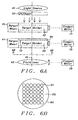
- FIG. 4B shows the image of the focus target 80 as seen by the MUT 51.
- the focus target consists of light areas (holes) 81 and dark areas (no-holes) 82.
- the preferred hole shape is circular; however, other shapes such as rectangular, hexagonal, octagonal, oval, etc., can be used.
- the holes 81 are relatively large for the far distance target 80 as compared to targets that are located closer to the MUT 51.
- the hole pattern shown in FIG. 4B is for illustrative purposes and is does not necessarily represent the hole pattern in the actual focus target.
- the focus stepper 44 (FIG. 3) adjusts the lens cap 49 until a maximum brightness is attained of the focus target image that is captured by the MUT 51. The point at which maximum brightness is obtained is approximately the best focus adjustment of the lens cap 49 for the far distance target.
- FIG. 5A is shown an intermediate focus target 85 located in an lower target position 73 of a target holder 42 of the upper target wheel 40.
- the target wheel is adjusted along the optical axis 46 by the stepper motor 77 to provide an intermediate focus target for the MUT 51 (FIG. 3).
- the field lens 43 is then adjusted by the stepper motor 79 to focus an image of the target 85 onto the lens opening on the lens cap 49 (FIG. 3).
- the adjustment setting of the stepper motors 77 and 79 are then recorder for use in the focusing of a MUT using the focus target 85.
- FIG. 5B shows the image of the focus target 85 as seen by the MUT 51.
- the focus target consists of light areas (holes) 86 and dark areas (no-holes) 82.
- the preferred hole shape is circular; however, other shapes such as rectangular, hexagonal, octagonal, oval, etc., can be used.
- the holes 86 are relatively smaller than the holes 81 on the far distance target 80 (FIG. 4A and 4B).
- the hole pattern shown in FIG. 5B is for illustrative purposes and is does not necessarily represent the hole pattern in the actual focus target.
- the focus stepper 44 (FIG. 3) adjusts the lens cap 49 until a maximum brightness is attained of the focus target image that is captured by the MUT 51. The point at which maximum brightness is obtained is approximately the best focus adjustment of the lens cap 49 for the intermediate distance target 85.
- FIG. 8B shows the image of the combination of focus targets 100 and 101 as seen by the MUT 51.
- the focus targets consists of light areas (holes) 81 and 96 and dark areas (no-holes) 82.
- the preferred hole shape is circular; however, other shapes such as rectangular, hexagonal, octagonal, oval, etc., can be used.
- the holes 96 of the close target 101 are smaller than the holes 81 on the farthest target 100.
- the hole pattern shown in FIG. 8B is for illustrative purposes and does not necessarily represent the hole pattern in the actual focus target.
- the focus stepper 44 (FIG. 3) adjusts the lens cap 49 until a maximum brightness is attained of the focus target image that is captured by the MUT 51.
- FIG. 9A a combination of a farthest focus target 105, two intermediate targets 106 and 107, and a closest target 108.
- Each of the targets 105, 106, 107 and 108 occupy a quarter of a target holder 42 is such a way that allows the four targets 105, 106, 107 and 108 to be viewed simultaneously by a MUT 51 (FIG. 3) as shown in FIG. 9B.
- the farthest focus target 105 is located in an upper target position 72 of a target holder 42 of the upper target wheel 40.
- the farthest focus target 105 occupies one quarter of the target position 72 of the upper target wheel 40 while the first intermediate target 106 occupies one quarter of the target position 73 of the upper target wheel.
- the second intermediate focus target 107 occupies one quarter of the target position 72 in the lower target wheel while and the closest focus target 108 occupies one quarter of the target position 73 of the lower target wheel 41.
- the target wheel 40 is adjusted along the optical axis 46 by the stepper motor 77 to provide a setting for the farthest focus target 105 from the MUT 51 (FIG. 3) and the target wheel 41 is adjusted along the optical axis 46 by the stepper motor 78 to provide a setting for the closest focus target 108 from the MUT 51.
- the field lens is then adjusted by the stepper motor 79 to focus a combination image of the targets 105, 106, 107 and 108 onto the lens opening on the lens cap 49 (FIG. 3).
- the adjustment setting of the stepper motors 77, 78 and 79 are then recorder for use in the focusing of a MUT using the combination of focus targets 105, 106, 107 and 108.
- FIG. 9B shows the image of the combination of focus targets 105, 106, 107 and 108 as seen by the MUT 51.
- the focus target consists of light areas (holes) 81, 86, 91 and 96 and dark areas (no-holes) 82.
- the preferred hole shape is circular; however, other shapes such as rectangular, hexagonal, octagonal, oval, etc., can be used.
- the holes 96 of the closest target 108 are the smallest followed by the second intermediate target 107 having the next smallest holes.
- the holes in the first intermediate target 106 are larger than the holes in the second intermediate target 107 while the holes in the farthest target 105 are the largest.
- the hole pattern shown in FIG. 8B is for illustrative purposes and does not necessarily represent the hole pattern in the actual focus target.
- the focus stepper 44 (FIG. 3) adjusts the lens cap 49 until a maximum brightness is attained of the focus target image that is captured by the MUT 51.
- the lens cap In focusing a MUT the lens cap is adjusted for a maximum contrast in the image between dark 82 and light areas 81, 86, 91 and 96 and also the sharpness of the transition between the dark and light areas.
- the brightness in LUX/lumen of the light areas 81, 86, 91 and 96 is measured and compared to an expected calculated value.
- An alternative approach is using a FFT (Fast Fourier Transform) that looks at frequency bins and the highest frequencies.
- the primary focus of a MUT uses the far targets 108 and close targets 105. If the image produced by the MUT for the far 108 and close target areas is within acceptable focus limits, then the MUT is considered to be in focus. It should be noted that the tester knows which area of the image represents represent the far 108, first intermediate 107, second intermediate 106 and close 105 target areas, and is easily able to operate on the respective areas to determine an acceptable focus.
- a light for illuminating the target is selected 121 and a test fixture containing the PFM is aligned with an optical centerline122.
- a target is selected 124 by rotating the target wheel until the target holder containing the focus target is over an optical centerline.
- the distance of the target wheel 125 from the PFM is adjusted using a stepper motor.
- the field lens is then adjusted 126 to focus the target onto the lens opening in the lens cap of the PFM.
- the stepper motors adjust the distance of the target wheel and the field lens until a maximum brightness of the image of the focus target is obtained by the PFM.
- the focus setup is then verified 127 by manual inspection.
- FIG. 11 is a flow diagram of a method for focusing a digital camera module under test (MUT).
- MUT digital camera module under test
- a light source is selected 140 to illuminate the focus targets.
- the focus target, or a combination of focus targets, that are to be used to focus the MUT are selected 141.
- the stepper motors 76 are used to position the selected target, or combination of targets, over the optical centerline of the test station by rotating the target wheels.
- a focus target, as shown in FIG. 4A through FIG. 7A, or a combination of focus targets, as shown in FIG. 8A and FIG. 9A, are selected by the rotational position of the target wheels.
- an untested MUT is loaded into a test fixture 143 from a transport tray14 (FIG. 1) containing digital camera modules.
- the test fixture is then aligned with an optical centerline of the test station 144.
- the MUT is focused 145 using a stepper motor driven focusing unit 44 (FIG. 3) that physically contacts the lens cap of the MUT and turns the lens cap to adjust the focus of the MUT.
- the lens cap is adjusted for a maximum contrast in the image between dark and light areas of the target as well as the sharpness of the transition between the dark and light areas.
- An alternative approach for determining a best focus is using a FFT (Fast Fourier Transform) to analyze frequency content and the highest frequencies of the FFT of a focus image of the MUT. If the MUT is found not to be able to be focused 146, the particular MUT is returned the transport tray. The inability to focus a MUT comprises a mechanical problem with the lens holder, dirt inside the MUT and a defect of the lens of the MUT. If the MUT can be focused 147, the MUT is then tested 148 and is unloaded from the test fixture to the transport tray upon completion of test 149. If there are additional untested digital camera modules on the transport tray 150, the focus and test procedure is repeated 140 through 150.
- FFT Fast Fourier Transform
- the transport tray 14 is moved to a tray out area 22 (FIG. 1) and the focus adjustment made on the digital camera modules during the focus procedure is permanently fixed 152 by use of glue or other mechanically fixing methods that permanently connect the lens cap to the body of the digital camera module and prevent the turning of the lens cap relative to the body of the module.
Landscapes
- Engineering & Computer Science (AREA)
- Multimedia (AREA)
- Signal Processing (AREA)
- Health & Medical Sciences (AREA)
- Biomedical Technology (AREA)
- General Health & Medical Sciences (AREA)
- Automatic Focus Adjustment (AREA)
- Investigating Materials By The Use Of Optical Means Adapted For Particular Applications (AREA)
- Lens Barrels (AREA)
Priority Applications (2)
| Application Number | Priority Date | Filing Date | Title |
|---|---|---|---|
| EP04368058A EP1628122A1 (de) | 2004-08-17 | 2004-08-17 | Scharfstellverfahren mit verschiedenen Zielradvorrichtungsdistanzen |
| US10/929,300 US7248347B2 (en) | 2004-08-17 | 2004-08-30 | Focus processing with the distance of different target wheels |
Applications Claiming Priority (1)
| Application Number | Priority Date | Filing Date | Title |
|---|---|---|---|
| EP04368058A EP1628122A1 (de) | 2004-08-17 | 2004-08-17 | Scharfstellverfahren mit verschiedenen Zielradvorrichtungsdistanzen |
Publications (1)
| Publication Number | Publication Date |
|---|---|
| EP1628122A1 true EP1628122A1 (de) | 2006-02-22 |
Family
ID=34931809
Family Applications (1)
| Application Number | Title | Priority Date | Filing Date |
|---|---|---|---|
| EP04368058A Withdrawn EP1628122A1 (de) | 2004-08-17 | 2004-08-17 | Scharfstellverfahren mit verschiedenen Zielradvorrichtungsdistanzen |
Country Status (2)
| Country | Link |
|---|---|
| US (1) | US7248347B2 (de) |
| EP (1) | EP1628122A1 (de) |
Cited By (4)
| Publication number | Priority date | Publication date | Assignee | Title |
|---|---|---|---|---|
| GB2426813A (en) * | 2005-06-02 | 2006-12-06 | Hi Key Ltd | A method and apparatus for testing the focus, alignment and field of view angle of a lens of a camera |
| US8305446B2 (en) * | 2006-07-07 | 2012-11-06 | Panasonic Corporation | Dome type monitor camera device |
| EP2941633A4 (de) * | 2013-01-04 | 2016-12-07 | Meso Scale Technologies Llc | Assay-vorrichtungen, -verfahren und -reagenzien |
| CN113452991A (zh) * | 2021-08-31 | 2021-09-28 | 南昌龙旗信息技术有限公司 | 镜头对焦状态确定方法、装置、设备及存储介质 |
Families Citing this family (10)
| Publication number | Priority date | Publication date | Assignee | Title |
|---|---|---|---|---|
| EP1628494A1 (de) * | 2004-08-17 | 2006-02-22 | Dialog Semiconductor GmbH | Intelligente Lichtquelle mit Synchronisation mit einer Digitalkamera |
| EP1628493A1 (de) * | 2004-08-17 | 2006-02-22 | Dialog Semiconductor GmbH | Handhabungssystem für Kamera |
| EP1648181A1 (de) | 2004-10-12 | 2006-04-19 | Dialog Semiconductor GmbH | Einzelbildabspeichervorrichtung |
| US20080169277A1 (en) * | 2007-01-16 | 2008-07-17 | Illinois Tool Works Inc. | Lighted welding torch |
| US8773539B2 (en) * | 2009-11-10 | 2014-07-08 | Ismedia Co., Ltd. | Camera module test and focus controlling apparatus |
| US8947537B2 (en) * | 2013-02-25 | 2015-02-03 | Teradyne, Inc. | Rotatable camera module testing system |
| US10955429B1 (en) * | 2017-12-06 | 2021-03-23 | National Technology & Engineering Solutions Of Sandia, Llc | Inspection workcell |
| US11012684B2 (en) * | 2018-12-19 | 2021-05-18 | Magna Electronics Inc. | Vehicular camera testing using a slanted or staggered target |
| US11491924B2 (en) * | 2020-09-22 | 2022-11-08 | Magna Electronics Inc. | Vehicular camera test system using true and simulated targets to determine camera defocus |
| US12503051B2 (en) | 2022-03-29 | 2025-12-23 | Magna Electronics Inc. | Vehicular camera focus test system using light collimator in controlled test chamber |
Citations (7)
| Publication number | Priority date | Publication date | Assignee | Title |
|---|---|---|---|---|
| EP0819927A2 (de) * | 1996-06-21 | 1998-01-21 | dSam Limited | Optischer Testapparat für ein optisches System |
| US6195159B1 (en) * | 1998-12-30 | 2001-02-27 | Agfa Corporation | Lens testing system |
| JP2002345001A (ja) * | 2001-05-21 | 2002-11-29 | Sharp Corp | オートフォーカス機能付きビデオカメラのピント判定装置及びピント判定方法 |
| US6512587B1 (en) * | 2000-10-27 | 2003-01-28 | Eastman Kodak Company | Measurement method and apparatus of an external digital camera imager assembly |
| US20030112360A1 (en) * | 2001-12-19 | 2003-06-19 | Fang-Yu Liao | Testing device for automatic exposure function of digital camera |
| EP1348996A1 (de) * | 2002-03-28 | 2003-10-01 | Eastman Kodak Company | System und Verfahren zur Kalibrierung einer Bildaufnahmevorrichtung |
| JP2004226462A (ja) * | 2003-01-20 | 2004-08-12 | Dainippon Printing Co Ltd | カメラのフォーカス調整方法および装置 |
Family Cites Families (25)
| Publication number | Priority date | Publication date | Assignee | Title |
|---|---|---|---|---|
| US4298944A (en) * | 1979-06-22 | 1981-11-03 | Siemens Gammasonics, Inc. | Distortion correction method and apparatus for scintillation cameras |
| US4612666A (en) * | 1984-07-05 | 1986-09-16 | The United States Of America As Represented By The Secretary Of The Navy | Automatic pattern recognition apparatus |
| EP0679932B1 (de) | 1988-08-01 | 2001-11-14 | Asahi Kogaku Kogyo Kabushiki Kaisha | ylektronisch gesteuerte Kamera |
| JP2841301B2 (ja) * | 1989-04-28 | 1998-12-24 | 池上通信機株式会社 | カラーテレビカメラの色補正装置 |
| JP2900425B2 (ja) | 1989-09-13 | 1999-06-02 | 富士通株式会社 | 画質検査装置 |
| US5649258A (en) * | 1995-12-08 | 1997-07-15 | Eastman Kodak Company | Apparatus for actuating and testing a camera |
| US6201600B1 (en) * | 1997-12-19 | 2001-03-13 | Northrop Grumman Corporation | Method and apparatus for the automatic inspection of optically transmissive objects having a lens portion |
| US6219443B1 (en) * | 1998-08-11 | 2001-04-17 | Agilent Technologies, Inc. | Method and apparatus for inspecting a display using a relatively low-resolution camera |
| JP4419265B2 (ja) | 2000-04-06 | 2010-02-24 | ソニー株式会社 | カメラの性能評価システム及びカメラの性能評価方法 |
| JP4423770B2 (ja) | 2000-08-31 | 2010-03-03 | ソニー株式会社 | カメラ特性評価用筐体、カメラ特性評価方法およびカメラ特性評価装置 |
| JP3585166B2 (ja) | 2001-01-29 | 2004-11-04 | シャープ株式会社 | カメラモジュールの画像検査装置およびカメラモジュールの画像検査方法 |
| JP2002290994A (ja) | 2001-03-26 | 2002-10-04 | Sharp Corp | 小型カメラモジュールの異物検査方法およびその異物検査装置 |
| US6714241B2 (en) | 2001-04-25 | 2004-03-30 | Hewlett-Packard Development Company, L.P. | Efficient dark current subtraction in an image sensor |
| US6798450B2 (en) | 2001-06-08 | 2004-09-28 | Hewlett-Packard Development Company, L.P. | Apparatus and method for reducing smear in digital images captured using frame-transfer CCD sensor |
| US20020191973A1 (en) | 2001-06-13 | 2002-12-19 | Hofer Gregory V. | Method and apparatus for focus error reduction in a camera |
| FI113132B (fi) | 2001-06-28 | 2004-02-27 | Nokia Corp | Menetelmä ja laite kuvanparannukseen |
| US6822657B2 (en) | 2001-08-10 | 2004-11-23 | Agilent Technologies, Inc. | Method and apparatus for improving image quality in digital cameras |
| JP3709362B2 (ja) | 2001-09-20 | 2005-10-26 | Necアクセステクニカ株式会社 | ディジタルカメラ装置 |
| JP2003179949A (ja) | 2001-12-12 | 2003-06-27 | Sharp Corp | 輝度レベル検査装置 |
| JP2003219436A (ja) | 2002-01-23 | 2003-07-31 | Fuminori Suzuki | 画素シフトカメラの調整のための装置と測定方法 |
| US7133148B2 (en) | 2002-01-25 | 2006-11-07 | Hewlett-Packard Development Company, L.P. | Digital camera for image device calibration |
| US20030146976A1 (en) | 2002-02-01 | 2003-08-07 | Tai-Li Liu | Digital camera system enabling remote monitoring |
| JP3902487B2 (ja) | 2002-03-01 | 2007-04-04 | ソニー株式会社 | 画像処理装置および方法、記録媒体、並びにプログラム |
| US7248284B2 (en) | 2002-08-12 | 2007-07-24 | Edward Alan Pierce | Calibration targets for digital cameras and methods of using same |
| US7068302B2 (en) | 2002-08-15 | 2006-06-27 | Ford Global Technologies, Llc | Method for camera calibration and quality testing |
-
2004
- 2004-08-17 EP EP04368058A patent/EP1628122A1/de not_active Withdrawn
- 2004-08-30 US US10/929,300 patent/US7248347B2/en not_active Expired - Fee Related
Patent Citations (7)
| Publication number | Priority date | Publication date | Assignee | Title |
|---|---|---|---|---|
| EP0819927A2 (de) * | 1996-06-21 | 1998-01-21 | dSam Limited | Optischer Testapparat für ein optisches System |
| US6195159B1 (en) * | 1998-12-30 | 2001-02-27 | Agfa Corporation | Lens testing system |
| US6512587B1 (en) * | 2000-10-27 | 2003-01-28 | Eastman Kodak Company | Measurement method and apparatus of an external digital camera imager assembly |
| JP2002345001A (ja) * | 2001-05-21 | 2002-11-29 | Sharp Corp | オートフォーカス機能付きビデオカメラのピント判定装置及びピント判定方法 |
| US20030112360A1 (en) * | 2001-12-19 | 2003-06-19 | Fang-Yu Liao | Testing device for automatic exposure function of digital camera |
| EP1348996A1 (de) * | 2002-03-28 | 2003-10-01 | Eastman Kodak Company | System und Verfahren zur Kalibrierung einer Bildaufnahmevorrichtung |
| JP2004226462A (ja) * | 2003-01-20 | 2004-08-12 | Dainippon Printing Co Ltd | カメラのフォーカス調整方法および装置 |
Non-Patent Citations (2)
| Title |
|---|
| PATENT ABSTRACTS OF JAPAN vol. 2003, no. 03 5 May 2003 (2003-05-05) * |
| PATENT ABSTRACTS OF JAPAN vol. 2003, no. 12 5 December 2003 (2003-12-05) * |
Cited By (6)
| Publication number | Priority date | Publication date | Assignee | Title |
|---|---|---|---|---|
| GB2426813A (en) * | 2005-06-02 | 2006-12-06 | Hi Key Ltd | A method and apparatus for testing the focus, alignment and field of view angle of a lens of a camera |
| US8305446B2 (en) * | 2006-07-07 | 2012-11-06 | Panasonic Corporation | Dome type monitor camera device |
| EP2941633A4 (de) * | 2013-01-04 | 2016-12-07 | Meso Scale Technologies Llc | Assay-vorrichtungen, -verfahren und -reagenzien |
| EP4345460A3 (de) * | 2013-01-04 | 2024-06-26 | Meso Scale Technologies, LLC. | Testvorrichtungen, verfahren und reagenzien |
| CN113452991A (zh) * | 2021-08-31 | 2021-09-28 | 南昌龙旗信息技术有限公司 | 镜头对焦状态确定方法、装置、设备及存储介质 |
| CN113452991B (zh) * | 2021-08-31 | 2021-11-23 | 南昌龙旗信息技术有限公司 | 镜头对焦状态确定方法、装置、设备及存储介质 |
Also Published As
| Publication number | Publication date |
|---|---|
| US20060038976A1 (en) | 2006-02-23 |
| US7248347B2 (en) | 2007-07-24 |
Similar Documents
| Publication | Publication Date | Title |
|---|---|---|
| US7812858B2 (en) | Camera handling system | |
| US7486309B2 (en) | Digital camera module test system | |
| US7248347B2 (en) | Focus processing with the distance of different target wheels | |
| US7403229B2 (en) | Testing of miniaturized digital camera modules with electrical and/or optical zoom functions | |
| US7158170B2 (en) | Test system for camera modules | |
| KR100622965B1 (ko) | 촬상 소자 시험 방법 및 장치 | |
| KR100709991B1 (ko) | 카메라 모듈 검사 장치 | |
| US20120229652A1 (en) | Camera module test and focus controlling apparatus | |
| US8068182B2 (en) | Multiple frame grabber | |
| US6760096B2 (en) | Lens-evaluating method and lens-evaluating apparatus | |
| US7525593B2 (en) | Position detection apparatus, position detection method, testing apparatus, and camera module manufacturing apparatus | |
| KR101640555B1 (ko) | 카메라 검사 장치 | |
| KR101863878B1 (ko) | 카메라 모듈 검사 장비 | |
| CN108540793B (zh) | 摄像模块的定位调校系统 | |
| KR101058603B1 (ko) | 이물 검사 방법 | |
| KR100878955B1 (ko) | 카메라모듈 이물검사장치 및 검사방법 | |
| KR102057118B1 (ko) | 다중 카메라를 이용한 카메라모듈의 외관 검사 장치 | |
| JP2007103787A (ja) | 固体撮像素子の検査装置 | |
| KR20220167911A (ko) | 배율 가변 기능을 갖는 칩 온 필름 검사장치 | |
| KR101923634B1 (ko) | 카메라 모듈 검사 장비 | |
| KR102045009B1 (ko) | 카메라 모듈 검사장치 | |
| TWI919783B (zh) | 圖像處理裝置以及圖像處理方法 | |
| TW202542483A (zh) | 圖像處理裝置以及圖像處理方法 |
Legal Events
| Date | Code | Title | Description |
|---|---|---|---|
| PUAI | Public reference made under article 153(3) epc to a published international application that has entered the european phase |
Free format text: ORIGINAL CODE: 0009012 |
|
| AK | Designated contracting states |
Kind code of ref document: A1 Designated state(s): AT BE BG CH CY CZ DE DK EE ES FI FR GB GR HU IE IT LI LU MC NL PL PT RO SE SI SK TR |
|
| AX | Request for extension of the european patent |
Extension state: AL HR LT LV MK |
|
| AKX | Designation fees paid | ||
| REG | Reference to a national code |
Ref country code: DE Ref legal event code: 8566 |
|
| STAA | Information on the status of an ep patent application or granted ep patent |
Free format text: STATUS: THE APPLICATION IS DEEMED TO BE WITHDRAWN |
|
| 18D | Application deemed to be withdrawn |
Effective date: 20060823 |