EP1630363B1 - Méthode pour déterminer la phase d'un arbre à cames dans un moteur à combustion interne - Google Patents
Méthode pour déterminer la phase d'un arbre à cames dans un moteur à combustion interne Download PDFInfo
- Publication number
- EP1630363B1 EP1630363B1 EP05016634A EP05016634A EP1630363B1 EP 1630363 B1 EP1630363 B1 EP 1630363B1 EP 05016634 A EP05016634 A EP 05016634A EP 05016634 A EP05016634 A EP 05016634A EP 1630363 B1 EP1630363 B1 EP 1630363B1
- Authority
- EP
- European Patent Office
- Prior art keywords
- value
- values
- angular speed
- rotational angle
- adjustment shaft
- Prior art date
- Legal status (The legal status is an assumption and is not a legal conclusion. Google has not performed a legal analysis and makes no representation as to the accuracy of the status listed.)
- Expired - Lifetime
Links
Images


Classifications
-
- F—MECHANICAL ENGINEERING; LIGHTING; HEATING; WEAPONS; BLASTING
- F01—MACHINES OR ENGINES IN GENERAL; ENGINE PLANTS IN GENERAL; STEAM ENGINES
- F01L—CYCLICALLY OPERATING VALVES FOR MACHINES OR ENGINES
- F01L1/00—Valve-gear or valve arrangements, e.g. lift-valve gear
- F01L1/34—Valve-gear or valve arrangements, e.g. lift-valve gear characterised by the provision of means for changing the timing of the valves without changing the duration of opening and without affecting the magnitude of the valve lift
- F01L1/344—Valve-gear or valve arrangements, e.g. lift-valve gear characterised by the provision of means for changing the timing of the valves without changing the duration of opening and without affecting the magnitude of the valve lift changing the angular relationship between crankshaft and camshaft, e.g. using helicoidal gear
-
- F—MECHANICAL ENGINEERING; LIGHTING; HEATING; WEAPONS; BLASTING
- F02—COMBUSTION ENGINES; HOT-GAS OR COMBUSTION-PRODUCT ENGINE PLANTS
- F02D—CONTROLLING COMBUSTION ENGINES
- F02D45/00—Electrical control not provided for in groups F02D41/00 - F02D43/00
-
- F—MECHANICAL ENGINEERING; LIGHTING; HEATING; WEAPONS; BLASTING
- F01—MACHINES OR ENGINES IN GENERAL; ENGINE PLANTS IN GENERAL; STEAM ENGINES
- F01L—CYCLICALLY OPERATING VALVES FOR MACHINES OR ENGINES
- F01L1/00—Valve-gear or valve arrangements, e.g. lift-valve gear
- F01L1/34—Valve-gear or valve arrangements, e.g. lift-valve gear characterised by the provision of means for changing the timing of the valves without changing the duration of opening and without affecting the magnitude of the valve lift
-
- Y—GENERAL TAGGING OF NEW TECHNOLOGICAL DEVELOPMENTS; GENERAL TAGGING OF CROSS-SECTIONAL TECHNOLOGIES SPANNING OVER SEVERAL SECTIONS OF THE IPC; TECHNICAL SUBJECTS COVERED BY FORMER USPC CROSS-REFERENCE ART COLLECTIONS [XRACs] AND DIGESTS
- Y10—TECHNICAL SUBJECTS COVERED BY FORMER USPC
- Y10T—TECHNICAL SUBJECTS COVERED BY FORMER US CLASSIFICATION
- Y10T29/00—Metal working
- Y10T29/49—Method of mechanical manufacture
- Y10T29/49002—Electrical device making
- Y10T29/49105—Switch making
Definitions
- the invention relates to a method for determining the rotational angle position of the camshaft of a reciprocating internal combustion engine relative to the crankshaft, wherein the crankshaft via a variable speed drive with the camshaft is in drive connection, which is designed as a three-shaft gear with a crankshaft fixed drive shaft, a camshaft fixed output shaft and an adjusting that is in driving connection with an adjusting motor, wherein for at least one crankshaft measuring time a measured value for the crankshaft rotation angle is detected, wherein for at least two Verstellwellen measuring times each measured value for the Verstellwellenen loftwinkel digitally detected, wherein for at least one reference time, the crankshaft and Verstellwellen-measuring times is based on at least one crankshaft rotation angle measurement, at least one Verstellwellenen loftwinkel measured value and a transmission characteristic of the three-shaft transmission, a value for the Dr ehwinkellage the camshaft is determined relative to the crankshaft.
- an epicyclic gear is provided as adjusting, with the drive shaft rotatably connected to a camshaft rotatably mounted relative to the camshaft gear, which is in driving connection via a drive chain with a crankshaft gear.
- An output shaft of the variable speed drive is in drive connection with the camshaft and an adjusting shaft with an adjusting motor.
- the drive shaft is stationary, there is a gear ratio predetermined by the adjusting gear between the adjusting shaft and the output shaft, the so-called stationary gear ratio.
- the rotational angle of the crankshaft and the adjusting shaft are first measured by means of inductive sensors and then using the known stationary gear ratio, an actual value signal for the phase angle of the camshaft is determined relative to the crankshaft.
- an interrupt is triggered in a microprocessor-based electronic control unit, in which the measured value for the Verstellwellenen loftwinkel is read into a control device and compared with a provided setpoint signal.
- the control device controls the EC motor in such a way that the deviation is reduced.
- This object is achieved by extrapolating from at least two Verstellwellenenairwinkel measured values, the time difference between the Verstellwellen-measuring times and the time interval between the last Verstellwellen-measuring time and the reference time for the angle of rotation, which has the adjusting shaft at the reference time, and that the value for the rotational angular position is determined on the basis of the estimated value, the at least one crankshaft rotational angle measured value and the transmission characteristic.
- the accuracy of the values for the phase angle is increased by the fact that the angle by which the adjusting shaft has rotated further between the last adjusting shaft measuring time and the respective current reference time is estimated and taken into account in the determination of the values for the phase position ,
- the inventive method thus enables a high precision in the determination of the phase position and a low power consumption of the adjusting motor.
- a value for the angular velocity of the adjusting shaft is determined at least for the respectively last adjusting shaft measuring time, wherein the estimated value for the rotational angle which the adjusting shaft has at the reference time consists of the last adjusting shaft rotational angle measured value, the time difference between the Reference time and the last Verstellwellen measuring time and the angular velocity value is determined.
- the Verstellwellenenburnwinkel measured value at the reference time is thus determined by linear interpolation from the last Verstellwellenenburnwinkel measured value using the angular velocity value.
- the angular velocity value can be calculated from the angular difference of the last two measured angular velocity values and the time difference between the measuring instants associated with these angular velocity values.
- the adjusting motor is an EC motor having a stator with a winding and a rotatably connected to the adjusting rotor, are arranged on the circumferentially offset from each other, magnetized in opposite directions magnetized magnet segments, the tolerances with respect to their positioning and / or their dimensions, wherein the position of the magnet segments relative to the stator is detected for detecting the Verstellwellenenburnwinkel measured values and / or the angular velocity values, wherein at least one correction value for compensating the influence of at least one tolerance on the Verstellwellenenburnwinkel measured values detected and wherein the Verstellwellenenburnwinkel measured values and / or the angular velocity values are corrected by means of the correction value.
- This embodiment is based on the finding that, in the case of a multiple passing movement of a magnetic segment of the rotor on a stationary magnetic sensor, the position measurement signal detected with the aid of the magnetic sensor always corresponds to the same magnet each time the magnetic sensor passes , Having error caused by the tolerance of the magnet segment.
- This error is determined by measurement or otherwise, to then determine a correction value with which the Verstellwellenen loftwinkel measured values are corrected at a later time when the relevant magnetic segment passes the magnetic field sensor again.
- a measurement inaccuracy caused by a tolerance of a magnet segment can be easily corrected in the speed signal. It is even possible to carry out this correction online at the currently measured speed value without a time delay occurring between the corrected speed value and the uncorrected speed value.
- the position of the magnetic segments is detected with the aid of a measuring device which has a plurality of magnetic field sensors on the stator, which are offset from one another in the circumferential direction of the stator in such a way that a number of magnetic segment sensor pulses are produced per revolution of the rotor relative to the stator. Combinations are traversed, and if for each of these magnetic segment sensor combinations each determines a correction value, stored and used to correct the Verstellwellen loftwinkel measured values and / or the angular velocity values. The phase angle of the camshaft relative to the crankshaft can then be adjusted with even greater precision.
- the number of magnetic segment-sensor combinations preferably corresponds to the product of the number of magnetic field sensors and the number of magnetic poles of the rotor.
- the rotor is rotated relative to the stator in such a way that a number of magnetic segment sensor combinations are traversed, with the aid of the measuring device detecting first uncorrected adjustment shaft rotation angle measurement values and / or angular velocity values for these magnetic segment sensor combinations
- reference values for the Verstellwellenenburnwinkel and / or the angular velocity are detected, which has a greater accuracy than that of the first Verstellwellenenburnwinkel measured values or angular velocity values, wherein using the first uncorrected Verstellwellenenburnwinkel measured values or angular velocity values, the correction values are determined as correction factors wherein the magnetic segment-sensor combinations assigned to the first uncorrected adjustment shaft rotation angle measurement values or angular velocity values again pass through and in this case with the aid of the measurement device second e uncorrected Verstellwellenen loftwinkel measured values or angular velocity values are detected, and wherein these values are corrected using the previously determined correction factors.
- the correction values are thus determined in the form of correction factors, which makes it possible to correct the measurement errors caused by the tolerances of the magnet segment at different rotational speeds.
- the reference signal may be a measurement signal that is detected, for example, in the manufacture of the EC motor by means of an additional position measuring device.
- the reference signal may also be a speed and / or an integrated acceleration signal of a shaft coupled to the EC motor.
- the reference values are formed by smoothing the first uncorrected adjustment shaft rotation angle measurement values or angular velocity values by filtering. As a result, an additional sensor for measuring the reference signal can be saved.
- the rotor is rotated relative to the stator such that the individual magnet segment sensor combinations occur at least twice, if a correction factor for the adjustment shaft rotation angle measurement values or angular velocity values is determined for the individual magnet segment sensor combinations if an average value is formed in each case from the correction factors determined for the individual magnet segment-sensor combinations, and if the mean values thus obtained are stored as new correction factors and the adjustment shaft rotation angle measurement values or angular velocity values when the magnet segment sensor combinations are re-run using the these correction factors are corrected.
- the individual magnetic segment sensor combinations are preferred to run through as often as possible, which is easily possible with an EC motor for an electronic camshaft adjustment, since this constantly rotates during operation of the internal combustion engine.
- the mean value is formed in each case as the arithmetic mean value. All the correction factors used for averaging enter into the mean value with the same weight.
- a mean moving average is formed in each case, preferably in such a way that the weight with which the correction factors enter the mean value decreases with increasing age of the correction factors. New correction factors are therefore taken more into account in the mean value than correction factors which are assigned to a date that lies further back. Should an error occur which leads to a situation where a magnetic segment / sensor combination is not recognized and thus the correction factors already determined are assigned to the wrong magnet segments, the incorrect correction factor assignment only has a short-term effect on the correction of the rotational speed signal, i. the wrong correction factors are "forgotten” relatively quickly.
- the Time T depends on the speed and decreases with increasing speed (event-controlled system).
- the assignment of the correction factors to the magnet segments can be restored if, for example, it should have been changed unintentionally due to a disturbance of the measurement signal.
- the already determined correction factors can be used even after the occurrence of the fault.
- an identifier on the rotor of the EC motor which allows an absolute measurement of the position of the rotor relative to the stator can be saved.
- the method can also be used after the EC motor has been switched back on to associate correction factors, which were determined during an earlier switch-on phase of the EC motor and stored in a non-volatile memory, with those magnet segment-sensor combinations for which they were determined during the earlier switch-on phase.
- correction factors can also be determined under ideal conditions in the manufacture of the EC motor, preferably in an end stage of production.
- the fluctuation ranges of the uncorrected angular velocity values and the corrected angular velocity values are each determined in a time window and compared with one another, wherein in the event that the fluctuation range of the corrected angular velocity values is greater than that of the uncorrected angular velocity values, the correction factors are newly determined and / or the assignment of the correction factors to the magnetic segment sensor combinations is restored. It is assumed that, in the event that the fluctuation of the corrected angular velocity values is greater than that of the uncorrected angular velocity values, an error has occurred in the assignment of the correction factors to the individual magnet segment-sensor combinations, for example by EMC irradiation. To correct this error, the correction factors can be reset to the value 1 and then re-adapted or the original assignment is restored, for example by cyclically interchanging the correction factors.
- the correction factors are limited to a predetermined value range, which is preferably between 0.8 and 1.2.
- a predetermined value range which is preferably between 0.8 and 1.2.
- a moment of inertia for the mass moment of inertia of the rotor is determined, wherein a current signal I is detected by a respective current value l (k) is determined for the individual Verstellwellen measuring times for the electric current in the winding, wherein for the individual angular velocity values ⁇ (k) are respectively determined from an angular velocity value ⁇ k (k-1) associated with a previous displacement wave measurement time, the current signal I and the moment of inertia value an estimated value ⁇ s (k) for the angular velocity value ⁇ (k), this estimated value ⁇ s (k) is assigned a tolerance band in which the estimated value ⁇ s (k) is included, and wherein in the case that the angular velocity value w (k) is outside the tolerance band, the angular velocity value w (k) by one within the Tolerance band located angular velocity value ⁇ k (k) is replaced.
- angular velocity values w (k) which lie outside the tolerance band and which are therefore not plausible are limited to the tolerance band, the limit values for the tolerance band being determined dynamically.
- fluctuations in the angular velocity values can be easily smoothed without there being any appreciable time delay between the smoothed angular velocity signal and the measured angular velocity signal.
- J is the mass moment of inertia of the rotor, w the rotor speed, K t a constant of the electric machine, I the winding current and t the time.
- the width ⁇ ⁇ limit of the tolerance band is preferably selected to be significantly smaller than the fluctuation range of the rotational speed measured values w (k) in order to achieve a noticeable reduction in the fluctuation of the angular velocity values.
- the rotor is loaded with a load torque, wherein a load torque signal M L is provided for the load torque, and wherein the estimated value ⁇ s (k) is in each case from the angular velocity value ⁇ k (k-1) assigned to the earlier sampling instant.
- the current signal I, the load torque signal M L and the moment of inertia value is determined.
- the voltage applied to the winding electrical voltage is detected, wherein the current values l (k) indirectly from the voltage, the impedance of the winding, the optionally corrected speed measurement w (k) and an engine constant K e is determined.
- R A is the ohmic resistance of the winding
- L A is the inductance of the winding
- K e is the motor constant of the EC motor.
- the method is preferably used in EC motors, in which the winding current is adjusted by pulse width modulation of an electrical voltage applied to the winding.
- the width and / or position of the tolerance band is selected as a function of the angular velocity value ⁇ k (k-1) assigned to the previous adjustment shaft measuring time and is preferably reduced with increasing angular velocity and / or increased with decreasing angular velocity. If there is an average value for the load torque of the camshaft, the accuracy of which depends on the rotational speed, the speed dependency of the accuracy in determining the width of the tolerance band can be taken into account.
- the width and / or position of the tolerance band is selected as a function of the current signal I and preferably increased with increasing current and / or reduced with decreasing current. It is assumed that in a large winding current of the rotor is usually accelerated so that the speed increases accordingly.
- the width and / or position of the tolerance band is thus adapted to the expected due to the energization of the winding speed changes of the rotor.
- the current signal I may be smoothed by filtering, in particular by moving averaging, and when the estimated values ⁇ s (k) for the angular velocity values w (k) are determined with the aid of the filtered current signal l.
- crankshaft rotation angle measurement values in each case at least two crankshaft rotation angle measurement values, the time difference between the crankshaft rotation angle measurement times assigned to these measurement values and the time interval between the last crankshaft measurement time and the reference time, an estimated value for the angle of rotation which the crankshaft has at the reference time , extrapolated, wherein the time difference between the reference time and the last crankshaft measuring time is determined, and wherein the estimated value of the crankshaft rotation angle measured value at the last crankshaft measuring time, the time difference and the angular speed value is determined.
- An adjusting device for adjusting the angle of rotation or phase of the camshaft 11 of a reciprocating internal combustion engine relative to the crankshaft 12 has an adjusting 13, which is designed as a three-shaft gear with a crankshaft fixed drive shaft, a camshaft fixed output shaft and a standing with the rotor of an adjusting motor in drive connection adjusting shaft ,
- a measured value for the crankshaft rotation angle is detected at each crankshaft measuring time.
- a measured value for the Verstellwellenenburnwinkel is measured at Verstellwellen-measuring times. From the measured value for the crankshaft rotation angle and the adjustment shaft rotation angle, a value for the phase position is determined with the aid of a known stationary gear ratio of the three-shaft transmission.
- an inductive sensor 15 is provided for measuring the crankshaft rotation angle, which detects the tooth flanks of a gear rim 16 consisting of a magnetically conductive material arranged on the crankshaft 12.
- a gear rim 16 consisting of a magnetically conductive material arranged on the crankshaft 12.
- One of the tooth gaps or teeth of the toothed rim 16 has a greater width than the other tooth gaps or teeth and serves as a reference mark.
- the measured value for the crankshaft rotation angle is set to a starting value. Thereafter, the measured value is tracked until the reference mark is passed by the sensor 15 each time a tooth flank is detected.
- the tracking of the measured value for the crankshaft angle takes place with the aid of a control device in whose operating program an interrupt is triggered in each case when a tooth flank is detected.
- the crankshaft rotation angle is therefore measured digitally.
- an EC motor 14 which has a rotor, on the circumference of a series of magnet sections alternately magnetized in opposite directions is arranged, which has an air gap with teeth of a stator interact magnetically. The teeth are wound with a winding, which is energized via a drive device.
- the position of the magnet segments relative to the stator and thus the Verstellwellenenburnwinkel is detected by means of a measuring device 17 having a plurality of magnetic field sensors A, B, C, which are arranged offset to one another in the circumferential direction of the stator to each other, that per revolution of the rotor a number is traversed by magnetic segment sensor combinations.
- a Hall sensor 18 is provided, which cooperates with a arranged on the camshaft 11 trigger 19. If the Hall sensor 18 detects an edge of the trigger wheel 19, an interrupt is triggered in the operating program of the control unit, in which the crankshaft rotation angle and the Verstellwellenenburnwinkel be cached. This interrupt will also be referred to as a camshaft interrupt below.
- the camshaft-triggered absolute angle ⁇ Abs and the relative displacement angle ⁇ Rel are currently calculated at the actual displacement angle ⁇ .
- a signal currently representing the current displacement angle ⁇ is present at an actual value input of a control circuit provided for controlling the phase position.
- the angular position ⁇ Rel of the camshaft 11 relative to the crankshaft 12 is calculated from the time-synchronous changes (controller sampling) of the angle counter of rotor ⁇ Em and crankshaft ⁇ KW relative to the reference values for camshaft triggering via the transmission fundamental equation of the three-shaft transmission:
- n kw 0
- the angles of the crankshaft ⁇ KW, TrigNW and the EC motor rotor or the adjusting shaft ⁇ Em, TrigNW are stored at the time of the camshaft trigger .
- an interrupt is then initiated in the operating program of the control device, in which the rotational angle position ⁇ Rel is calculated with the aid of the intermediately stored angles ⁇ KW, TrigNW and ( ⁇ Em, TrigNW .
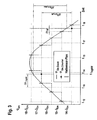
- the resolution of the relative angular position ⁇ Rel results from an uncertainty analysis of the individual components of Eq. (1.1).
- the crankshaft rotation angle has, for example, an uncertainty of -0 to + 0.2 °.
- the uncertainty band at positive speed
- TrigNW - 0 + 8:57
- the digitization of the Verstellwellenen loftwinkels causes a kind of beating between the times at which the cyclic interrupt occurs, and the times at which the magnetic segment sensor combinations change.
- the EC motor 14 rotates exactly twice as fast as the crankshaft 12.
- the times at which the cyclic interrupt occurs differ from the times at which the magnetic segment-sensor combinations alternate.
- nine changes occur The magnetic segment-sensor combinations within eight interrupt cycles, ie per interrupt cycle, the electric motor covers an angle of (9/8) * 8.57 °.
- an extrapolation of in each case at least two adjustment shaft rotation angle measurement values is an estimated value for the angle of rotation which the adjustment shaft has at reference point which lies after the adjustment shaft measurement times.
- the points in time at which the camshaft interrupts occur and, on the other hand, the points in time at which the cyclic interrupts are triggered are selected as reference times.
- TrigNW N TrigNW ⁇ ⁇ em + ⁇ ⁇ t TrigNW ⁇ ⁇ em .
- TrigNW ⁇ em . ti N ti ⁇ ⁇ em + ⁇ ⁇ t i ⁇ ⁇ em . ti
- TrigNW N ti - N TrigNW ⁇ ⁇ em + ⁇ ⁇ t i ⁇ ⁇ em . ti - ⁇ ⁇ t TrigNW ⁇ ⁇ em .
- This method is very simple, but can give very variable values, since the times ⁇ t Hall between the changes of the magnetic segment-sensor combination can be very irregular even at constant speed due to manufacturing tolerances. Basically, in order to improve the result, it is possible to average over several adjustment shaft angular values. It should be noted, however, that the mean value can only be calculated with a time delay so that when the EC motor 14 accelerates, this error is included in the extrapolation. In the ECU interrupt, the current speed ⁇ Em of the EC motor 14 is also calculated for the control of the phase angle.
- the rotor has eight magnet segments 1..8, which are offset in a grid of 45 ° in the circumferential direction of a support member 9 to which the magnet segments are fixed 1..8, to each other.
- the magnet segments 1..8 each form a magnetic pole on the circumference of the rotor, resulting in a total of a number of p pole pairs over the circumference.
- the magnetization On the ring formed by the magnet segments 1..8, the magnetization thus changes direction 8 times per revolution.
- the mechanical angle ⁇ between mutually corresponding points of adjacent magnet segments 1. 8 can thus deviate from the nominal value 180 ° / p (in this case 45 °).
- the direction of rotation of the runner is in Fig. 4 indicated by the arrow Pf.
- the output signal of the magnetic field sensor A changes in each case during a rotation of the rotor by the angle ⁇ .
- a resolution of the rotor angle of rotation of ⁇ could thus be achieved.
- the sensors A, B, C are arranged offset from one another on the circumference of the rotor. The offset is chosen such that the position measurement signal detected with the aid of the sensors A, B, C has a resolution of 180 ° / (p ⁇ m).
- FIG. 5 is a portion of the composed of the output signals A ', B', C 'of the sensors A, B, C Verstellwellenenfitskysignals for a clockwise rotation in the direction of the arrow Pf shown.
- the output signal A ' is assigned to the magnetic field sensor A, the output signal B' to the magnetic field sensor B, etc.
- the output signals A ', B', C ' are digital signals which can assume the logic values 1 or 0. In this case, the value 1 occurs when the respective sensor A, B, C is opposite to a north pole forming magnetic segment 1..8.
- the Verstellwellenen loftwinkelsignal composed of the output signals A ', B' and C ' is transmitted for evaluation to the control unit, which is connected to the magnetic field sensors A, B, C. Only the output signals A ', B' and C 'are known to the control unit, but not which magnetic segments 1. 8 are being moved past the sensors A, B, C.
- Fig. 5 It can be seen that always one of the magnet segment sensor combinations is currently active. In Fig. 5 From left to right, these are the magnet segment sensor combinations (1,6,3), (1,6,4), (1,7,4), (2,7,4), (2,7,5 ), (2,8,5), etc. This sequence of magnetic segment-sensor combinations is repeated after 2 ⁇ p magnetic segments 1..8 have passed a magnetic field sensor A, B, C, ie after a mechanical full rotation.
- the total rotation angle of the rotor is determined. Starting from a start value, the total angle is incremented with each change.
- the speed signal ⁇ measured , i determined in this way is subject to errors which, for example, lead to a jump in the speed signal at a constant actual rotational speed of the rotor.
- the magnetic segment sensor combinations of 1 to 2 * m * p are numbered consecutively, so that the count, hereinafter referred to as "index i", starts up and then jumps to 1 upon reaching 2 * m * p ,
- the index i is set to a starting value, e.g. to the value 1.
- a correction factor F Adap [i] is now determined, which is assigned to the corresponding magnet segment 1..8 via the index i.
- This correction factor F Adap [i] corresponds to the ratio between the rotational speed value ⁇ Mess, i , which is determined by means of the adjustment shaft rotation angle signal for the ith magnet segment-sensor combination was determined, and a reference rotational speed ⁇ Ref , which is assumed to have a greater accuracy than the rotational speed value ⁇ Mess, i .
- the correction factors F Adap [i] are stored in a data memory of the control unit.
- the correction factors F Adap [i] are determined in a learning process. At the start of the learning process, all correction factors F Adap [i] are set to the value 1, ie the corrected rotational speed ⁇ Korr, i initially corresponds to the measured rotational speed ⁇ Mess, i . During the learning process, the correction factors F Adap [i] are limited to a value range between 0.8 and 1.2 in order to limit the amount of error in the event of an incorrect adaptation, which in practice can not be completely ruled out.
- a key point in the adaptation is the accuracy with which the actual speed is approximated. In the embodiment described above, this approximation is achieved by filtering the measured speed. But it is also possible to filter the already corrected speeds. If another measuring signal is available, from which the actual speed can be concluded, then this can also be used.
- the 2 * p * m learned correction factors are written to a nonvolatile data memory of the controller. Since, at the beginning of the adaptation, the index i is set to a randomly selected starting value for a magnet segment-sensor combination which was just accidentally active, and this magnet segment-sensor combination is initially unknown after the controller is switched on again, the assignment of the correction factors be checked to the magnetic segment sensor combinations and corrected in the determination of a faulty assignment, so that the correction factors can be used after restarting the controller.
- the quality of the adaptation is monitored by repeatedly comparing the fluctuation range of the uncorrected and the corrected rotational speed over a specific time window. If the corrected speed fluctuates more than the uncorrected speed, an erroneous assignment is concluded. The assignment is then either restored or the correction factors are set to 1.
- the number sequence of the 2 ⁇ p ⁇ m correction factors represents a type of characteristic signature. If you adapt a new set of correction factors, they must have a very similar sequence of numbers, but the new sequence of numbers may be shifted from the previous sequence of numbers. To restore the assignment, the old sequence of numbers is therefore cyclically shifted 2 ⁇ p ⁇ m times and compared to the previous sequence of numbers after each shift step. In the case of the interchange combination in which the greatest correspondence between the old and the previous number sequence occurs, it is assumed that the numerical values of the old sequence of numbers are correctly assigned to the magnetic segment-sensor combinations. With this assignment, the correction of the speed signal and / or the further adaptation is then carried out.
- the corrected speed is calculated either with the factor 1 or with the previously adapted correction factors.
Landscapes
- Engineering & Computer Science (AREA)
- Mechanical Engineering (AREA)
- General Engineering & Computer Science (AREA)
- Chemical & Material Sciences (AREA)
- Combustion & Propulsion (AREA)
- Measurement Of Length, Angles, Or The Like Using Electric Or Magnetic Means (AREA)
- Control Of Motors That Do Not Use Commutators (AREA)
- Combined Controls Of Internal Combustion Engines (AREA)
- Valve-Gear Or Valve Arrangements (AREA)
- Output Control And Ontrol Of Special Type Engine (AREA)
- Length Measuring Devices With Unspecified Measuring Means (AREA)
- Transmission And Conversion Of Sensor Element Output (AREA)
Claims (24)
- Procédé pour déterminer la position d'angle de rotation de l'arbre à cames (11) d'un moteur à combustion interne à piston alternatif par rapport au vilebrequin (12), le vilebrequin (12) étant en liaison d'entraînement avec l'arbre à cames (11) par l'intermédiaire d'une boîte ajustable, qui est conçue sous la forme d'une boîte à trois arbres avec un arbre primaire stationnaire sur le vilebrequin, un arbre de sortie stationnaire sur l'arbre à cames et un arbre d'ajustage, qui est en liaison d'entraînement avec un moteur d'ajustage, pour au moins un moment de mesure sur le vilebrequin, une valeur mesurée pour l'angle de rotation du vilebrequin étant détectée, pour au moins deux moments de mesure sur l'arbre d'ajustage, chaque fois une valeur mesurée pour l'angle de rotation de l'arbre d'ajustage étant détectée de façon numérique, pour au moins un moment de référence, qui est postérieur aux moments de mesure sur le vilebrequin et sur l'arbre d'ajustage, à l'aide d'au moins une valeur mesurée pour l'angle de rotation du vilebrequin, d'au moins une valeur mesurée pour l'angle de rotation de l'arbre d'ajustage et d'une valeur caractéristique de la boîte à trois arbres, une valeur étant déterminée pour la position d'angle de rotation de l'arbre à cames (11) par rapport au vilebrequin (12), caractérisé en ce que, à partir d'au moins deux valeurs mesurées pour l'angle de rotation de l'arbre d'ajustage, de la différence de temps entre les moments de mesure sur l'arbre d'ajustage et de l'intervalle de temps entre le dernier moment de mesure sur l'arbre d'ajustage et le moment de référence, une valeur estimative est extrapolée pour l'angle de rotation que l'arbre d'ajustage présente au moment de référence, et en ce que, à l'aide de la valeur estimative, de l'au moins une valeur mesurée pour l'angle de rotation du vilebrequin et de la valeur caractéristique de la boîte, la valeur pour la position d'angle de rotation est déterminée.
- Procédé selon la revendication 1, caractérisé en ce qu'au moins pour le dernier moment de mesure respectif sur l'arbre d'ajustage, une valeur est déterminée pour la vitesse angulaire de l'arbre d'ajustage et en ce que la valeur estimative pour l'angle de rotation que l'arbre d'ajustage présente au moment de référence est déterminée à partir de la dernière valeur mesurée pour l'angle de rotation de l'arbre d'ajustage, de la différence de temps entre le moment de référence et le dernier moment de mesure sur l'arbre d'ajustage, ainsi que de la valeur de vitesse angulaire.
- Procédé selon la revendication 1 ou 2, caractérisé en ce que le moteur d'ajustage est un moteur EC (14) qui dispose d'un stator avec un enroulement et avec un induit relié de façon solidaire en rotation avec l'arbre d'ajustage, sur lequel en direction périphérique sont disposés des segments d'aimants (1 ... 8) déportés les uns par rapport aux autres, aimantés en alternance dans des directions mutuellement opposées, qui présentent des tolérances au niveau de leur positionnement et/ou de leurs dimensions, en ce que pour la détection des valeurs mesurées pour l'angle de rotation de l'arbre d'ajustage et/ou des valeurs de vitesse angulaire, la position des segments d'aimants (1 ..8) par rapport au stator est détectée, en ce qu'au moins une valeur de correction pour la compensation de l'influence d'au moins une tolérance sur les valeurs mesurées pour l'angle de rotation de l'arbre d'ajustage est détectée et en ce que les valeurs mesurées pour l'angle de rotation de l'arbre d'ajustage et/ou les valeurs de vitesse angulaire sont corrigées à l'aide de la valeur de correction.
- Procédé selon l'une quelconque des revendications 1 à 3, caractérisé en ce que la position des segments d'aimants (1..8) est détectée à l'aide d'un dispositif de mesure (17) qui, sur le stator comporte plusieurs capteurs de champ magnétique, qui sont disposés en étant déportés les uns par rapport aux autres dans la direction périphérique du stator de sorte que, pour chaque rotation de l'induit par rapport au stator, un nombre de combinaisons de segment d'aimant/capteur est passé, et en ce que pour chacune desdites combinaisons de segment d'aimant/capteur on détermine, on mémorise et on utilise pour la correction des valeurs mesurées pour l'angle de rotation de l'arbre d'ajustage et/ou pour les valeurs de vitesse angulaire chaque fois une valeur de correction.
- Procédé selon l'une quelconque des revendications 1 à 4, caractérisé en ce que, l'induit se tourne par rapport au stator de sorte qu'un nombre de combinaisons segment d'aimant/capteur soit passé, en ce qu'à l'aide du dispositif de mesure (17) des premières valeurs mesurées pour l'angle de rotation de l'arbre d'ajustage et/ou des valeurs de vitesse angulaire non corrigées sont détectées pour lesdites combinaisons de segment d'aimant/capteur, en ce que en supplément, des valeurs de référence pour l'angle de rotation de l'arbre d'ajustage et/ou pour la vitesse angulaire sont détectées, qui font preuve d'une plus grande précision que les premières valeurs mesurées pour l'angle de rotation de l'arbre d'ajustage ou valeurs de vitesse angulaire un corrigées, en ce qu'à l'aide des premières valeurs mesurées pour l'angle de rotation de l'arbre d'ajustage ou des valeurs de vitesse angulaire non corrigées, les valeurs de correction sont déterminées en tant que coefficients de correction, en ce que les combinaisons de segment d'aimant/capteur associées aux premières valeurs mesurées pour l'angle de rotation de l'arbre d'ajustage, ou valeurs de vitesse angulaire non corrigées sont passées une fois encore et à cet effet, à l'aide du dispositif de mesure (17) des deuxièmes valeurs mesurées pour l'angle de rotation de l'arbre d'ajustage ou valeurs de vitesse angulaire non corrigées sont détectées et en ce que lesdites valeurs sont corrigées à l'aide des coefficients de correction précédemment déterminés.
- Procédé selon l'une quelconque des revendications 1 à 5, caractérisé en ce que les valeurs de référence sont créées en ce qu'on lisse par filtrage les premières valeurs mesurées pour l'angle de rotation de l'arbre d'ajustage ou valeurs de vitesse angulaire non corrigées.
- Procédé selon l'une quelconque des revendications 1 à 6, caractérisé en ce que l'induit se tourne par rapport au stator de sorte que les combinaisons individuelles segment d'aimant/capteur se présentent au moins deux fois, en ce qu'à cet effet, pour les combinaisons individuelles segment d'aimant/capteur chaque fois un coefficient de correction est déterminé pour les valeurs mesurées pour l'angle de rotation de l'arbre d'ajustage, respectivement pour les valeurs de vitesse angulaire, en ce qu'à partir des coefficients de correction déterminés pour les combinaisons individuelles segment d'aimant/capteur, une valeur moyenne est chaque fois formée, et en ce que les valeurs moyennes ainsi obtenues sont mémorisées en tant que nouveaux coefficients de correction, et en ce que les valeurs mesurées pour l'angle de rotation de l'arbre d'ajustage ou les valeurs de vitesse angulaire sont corrigées à l'aide desdits coefficients de correction, lors d'un nouveau passage des combinaisons segment d'aimant/capteur.
- Procédé selon l'une quelconque des revendications 1 à 7, caractérisé en ce que chaque fois la valeur arithmétique moyenne est formée en tant que valeur moyenne.
- Procédé selon l'une quelconque des revendications 1 à 8, caractérisé en ce qu'en tant que valeur moyenne, il est formé chaque fois une valeur moyenne mobile, de préférence de sorte que le poids, avec lequel les coefficients de correction se répercutent sur la valeur moyenne décroisse au fur et à mesure de l'avancement en ancienneté des coefficients de correction.
- Procédé selon l'une quelconque des revendications 1 à 9, caractérisé en ce que les valeurs moyennes mobiles FNouv[i(t-T)] pour les combinaisons individuelles segment d'aimant/capteur sont déterminées de façon cyclique selon la formule FNouv [i(t-T)] = λFAnc [i(t-T)] + (1-λ) F[i(t-T)], i étant un indice identifiant la combinaison respective segment d'aimant/capteur, t étant le temps, T étant une temporisation entre la vitesse angulaire réelle et les valeurs mesurées pour la vitesse angulaire, FAnc[i(t-T)] étant la valeur moyenne déterminée sur l'indice i lors du dernier calcul de la valeur moyenne et λ étant un coefficient d'oubli, qui est supérieur à zéro et inférieur à 1 et qui se situe de préférence dans l'intervalle entre 0,7 et 0,9.
- Procédé selon l'une quelconque des revendications 1 à 12, caractérisé en ce quea) l'induit se tourne par rapport au stator et les coefficients de correction sont déterminés et mémorisés pour les combinaisons individuelles segment d'aimant/capteur,b) en ce qu'ensuite, les combinaisons correspondantes segment d'aimant/capteur sont passées une nouvelle fois, un jeu de nouveaux coefficients de correction étant déterminé,c) en ce que les coefficients de correction de l'ancien jeu de coefficients de correction sont cycliquement échangés contre ceux du nouveau jeu de coefficients de correction et en ce que les jeux de coefficients de correction sont ensuite comparés entre eux,d) en ce que l'étape c) se répète jusqu'à ce que toutes les combinaisons de permutation de l'ancien jeu de coefficients de correction aient été comparées avec le nouveau jeu de coefficients de correction,e) en ce que la combinaison de permutation, présentant une concordance maximum avec le nouveau jeu de coefficients de correction est déterminée,f) et en ce que les valeurs de vitesse angulaire sont corrigées avec la structure des valeurs de correction de l'ancien jeu de coefficients de correction qui est affectée à cette combinaison de permutation.
- Procédé selon la revendication 11, caractérisé en ce qu'à partir des coefficients de correction de l'ancien jeu de coefficients de correction et du nouveau jeu de coefficients de correction, respectivement mutuellement affectés lors de la combinaison de permutations au cours de laquelle il se produit une concordance maximale entre les jeux de coefficients de correction, il est calculé chaque fois une valeur moyenne qui est mémorisée en tant que nouveau coefficient de correction et en ce qu'avec le jeu de coefficients de correction obtenu par ledit calcul de la valeur moyenne, les valeurs de vitesse angulaire sont corrigées.
- Procédé selon l'une quelconque des revendications 1 à 12, caractérisé en ce que,a) l'induit se tourne par rapport au stator de sorte que toutes les combinaisons segment d'aimant/capteur soient passées au moins une fois,b) en ce qu'à cet effet, un signal de mesure de position des capteurs de champ magnétique est généré de sorte que, par rotation du moteur EC (14) pour chaque paire de pôles de l'induit, chaque fois un nombre d'états de signaux de mesure est passé,c) en ce qu'un premier jeu de données, avec un nombre de combinaisons de valeurs correspondant au nombre de combinaisons segment d'aimant/capteur, consistant chacune en au moins un coefficient de correction pour la combinaison segment d'aimant/capteur concernée et un état de signal de mesure correspondant à cette dernière est déterminé et mémorisé,d) en ce qu'ensuite, les combinaisons correspondantes segment d'aimant/capteur sont passées une nouvelle fois, un nouveau, deuxième jeu de données avec des combinaisons de valeurs étant déterminé et mémorisé,e) en ce que, lors d'un écart entre les états des signaux de mesure du premier et du deuxième jeu de données, les combinaisons de valeurs du premier jeu de données sont déplacées cycliquement par rapport à celles du deuxième jeu de données, de sorte que les états de signaux de mesure des jeux de données concordent,f) en ce qu'ensuite, les coefficients de correction chaque fois mutuellement affectés des jeux de données sont comparés entre eux,g) en ce que les coefficients de correction d'un jeu de données sont échangés cycliquement d'un nombre d'étapes correspondant au double du nombre des capteurs de champ magnétique par rapport aux coefficients de correction de l'autre jeu de données et ensuite les coefficients de correction respectivement affectés les uns aux autres des jeux de données sont comparés entre eux,h) en ce que l'étape g) se répète le cas échéant, jusqu'à ce que toutes les combinaisons de permutations aient été traitées,i) en ce qu'une combinaison de permutations est déterminée, avec laquelle il se présente une concordance maximale entre les coefficients de correction des jeux de données,j) et en ce que les valeurs de vitesse angulaire sont corrigées avec la structure des valeurs de correction du premier jeu de données qui est affectée à cette combinaison de permutations.
- Procédé selon la revendication 13, caractérisé en ce qu'à partir des coefficients de correction du premier et du deuxième jeu de données respectivement mutuellement affectés lors de la combinaison de permutations, au cours de laquelle il se produit une concordance maximale entre les coefficients de correction des jeux de données, il est calculé chaque fois une valeur moyenne qui est mémorisée en tant que nouveau coefficient de correction, et en ce que les valeurs de vitesse angulaire sont corrigées avec le jeu de coefficients de correction obtenu par ce calcul de la valeur moyenne.
- Procédé selon l'une quelconque des revendications 1 à 14, caractérisé en ce que les amplitudes de variation des valeurs de vitesse angulaire non corrigées et des valeurs de vitesse angulaire corrigées sont déterminées dans une fenêtre de temps et comparées les unes aux autres, et en ce que dans le cas où l'amplitude de variation des valeurs de vitesse angulaire corrigées est supérieure à celle des valeurs de vitesse angulaire non corrigées, les coefficients de correction sont redéterminés et/ou l'affection des coefficients de correction aux combinaisons segment d'aimant/capteur est réétablie.
- Procédé selon l'une quelconque des revendications 1 à 15, caractérisé en ce que les coefficients de correction sont limités à une plage de valeurs prédéfinie, qui est comprise de préférence entre 0,8 et 1,2.
- Procédé selon l'une quelconque des revendications 1 à 16, caractérisé en ce qu'une valeur de moment d'inertie pour le moment d'inertie des masses de l'induit est déterminée, en ce qu'un signal électrique I est déterminé, en ce que pour les moments de mesure individuels sur l'arbre d'ajustage, chaque fois une valeur de courant I(k) est déterminée pour le courant électrique dans l'enroulement, en ce que pour les valeurs individuelles de vitesse angulaire ω(k), chaque fois à partir d'une valeur de vitesse angulaire ωk(k-1), affectée à un moment de mesure ultérieur sur l'arbre d'ajustage, du signal électrique I et de la valeur du moment d'inertie une valeur estimative ws(k) est déterminée pour la valeur de vitesse angulaire ω(k), en ce qu'il est affecté à cette valeur estimative ωs(k) une bande de tolérances dans laquelle la valeur estimative ws (k) est comprise, et en ce que dans le cas où la valeur de vitesse angulaire ω(k) se situe hors de la bande de tolérances, la valeur de vitesse angulaire ω(k) est remplacée par une valeur de vitesse angulaire ωk(k) située dans la bande de tolérances.
- Procédé selon l'une quelconque des revendications 1 à 17, caractérisé en ce que l'induit est contraint par un couple résistant, en ce que, pour le couple résistant, il est mis à disposition un signal de couple résistant ML et en ce que la valeur estimative ωs(k) est déterminée chaque fois à partir de la valeur de vitesse angulaire ωk(k-1) affectée à l'ancien moment de balayage, à partir du signal électrique I, à partir du signal de couple résistant ML et à partir de la valeur du moment d'inertie.
- Procédé selon l'une quelconque des revendications 1 à 18, caractérisé en ce que la tension électrique appliquée sur l'enroulement est détectée et en ce que les valeurs de courant I(k) sont déterminées indirectement à partir de la tension, de l'impédance de l'enroulement, des valeurs de vitesse angulaire ωk(k) corrigées le cas échéant et d'une constante du moteur.
- Procédé selon l'une quelconque des revendications 1 à 19, caractérisé en ce que la bande de tolérances est limitée par des valeurs marginales, et en ce que les valeurs de vitesse angulaire ω(k), qui se situent hors de la bande de tolérances, sont corrigées à la valeur marginale de la bande de tolérances la plus proche de celles-ci.
- Procédé selon l'une quelconque des revendications 1 à 20, caractérisé en ce que la largeur et/ou la position de la bande de tolérance sont choisies en fonction de la valeur de vitesse angulaire ωk(k-1) affectée à l'ancien moment de mesure sur l'arbre d'ajustage et en ce qu'elles sont de préférence réduites au fur et à mesure que la vitesse angulaire augmente et/ou augmentées au fur et à mesure que la vitesse angulaire se réduit.
- Procédé selon l'une quelconque des revendications 1 à 21, caractérisé en ce que la largeur et/ou la position de la bande de tolérances sont choisies en fonction du signal électrique I et en ce qu'elles sont de préférence augmentées au fur et à mesure de l'augmentation du courant et/ou réduites au fur et à mesure de la réduction du courant.
- Procédé selon l'une quelconque des revendications 1 à 22, caractérisé en ce que le signal électrique I est lissé par filtrage, notamment par un calcul de valeurs moyennes mobiles, et en ce que les valeurs estimatives ωs(k) pour les valeurs de vitesse angulaire ω(k) sont déterminées à l'aide du signal électrique I filtré.
- Procédé selon l'une quelconque des revendications 1 à 23, caractérisé en ce que respectivement à partir d'au moins deux valeurs mesurées pour l'angle de rotation du vilebrequin, à partir de la différence de temps entre les moments de mesure de l'intervalle de rotation du vilebrequin affectés auxdites valeurs mesurées, ainsi qu'à partir de l'écart de temps entre le dernier moment de mesure sur le vilebrequin et le point de référence, une valeur estimative pour l'angle de rotation, que présente le vilebrequin (12) au moment de référence, est extrapolée, en ce que la différence de temps entre le moment de référence et le dernier moment de mesure sur le vilebrequin est déterminée et en ce que la valeur estimative est définie à partir de la valeur mesurée pour l'angle de rotation du vilebrequin au dernier moment de mesure sur le vilebrequin, à partir de la différence de temps et de la valeur de vitesse angulaire.
Applications Claiming Priority (1)
| Application Number | Priority Date | Filing Date | Title |
|---|---|---|---|
| DE102004041712 | 2004-08-28 |
Publications (2)
| Publication Number | Publication Date |
|---|---|
| EP1630363A1 EP1630363A1 (fr) | 2006-03-01 |
| EP1630363B1 true EP1630363B1 (fr) | 2008-04-09 |
Family
ID=34937928
Family Applications (1)
| Application Number | Title | Priority Date | Filing Date |
|---|---|---|---|
| EP05016634A Expired - Lifetime EP1630363B1 (fr) | 2004-08-28 | 2005-07-30 | Méthode pour déterminer la phase d'un arbre à cames dans un moteur à combustion interne |
Country Status (7)
| Country | Link |
|---|---|
| US (1) | US7254991B2 (fr) |
| EP (1) | EP1630363B1 (fr) |
| JP (1) | JP2006064704A (fr) |
| KR (1) | KR101256661B1 (fr) |
| AT (1) | ATE391836T1 (fr) |
| DE (1) | DE502005003618D1 (fr) |
| ES (1) | ES2305959T3 (fr) |
Families Citing this family (30)
| Publication number | Priority date | Publication date | Assignee | Title |
|---|---|---|---|---|
| DE102006017232A1 (de) * | 2006-04-12 | 2007-10-25 | Schaeffler Kg | Synchronisationsvorrichtung für einen Motor |
| US7814780B2 (en) * | 2007-04-09 | 2010-10-19 | Bg Soflex Llc | Engine position tracking for internal combustion engines |
| DE102007060604A1 (de) * | 2007-12-13 | 2009-06-18 | Continental Teves Ag & Co. Ohg | Magnetfeld-Sensorelement |
| US7775090B1 (en) * | 2008-03-27 | 2010-08-17 | Honda Motor Co., Ltd. | Inductively coupleable pulse generator plate detector and method of pulse generator plate detection |
| KR100957198B1 (ko) * | 2008-05-29 | 2010-05-11 | 한양대학교 산학협력단 | 구동축의 회전각 측정 시스템 |
| DE102008039007A1 (de) | 2008-08-21 | 2010-02-25 | Schaeffler Kg | Verfahren zur Verstellung einer Kurbelwelle eines Verbrennungsmotors, Nockenwellenverstellsystem und Verbrennungsmotor mit verstellbarer Kurbelwelle |
| US8096271B2 (en) * | 2009-06-01 | 2012-01-17 | GM Global Technology Operations LLC | System and method for determining a camshaft position in a variable valve timing engine |
| JP4803286B2 (ja) * | 2009-07-31 | 2011-10-26 | 株式会社デンソー | 車両の走行用モータ制御装置 |
| US8487563B2 (en) * | 2009-11-27 | 2013-07-16 | Denso Corporation | Drive motor control apparatus for vehicle, motor control system, method for correcting rotation angle of motor, program for performing the same, rotation detecting apparatus |
| FR2967770B1 (fr) * | 2010-11-18 | 2012-12-07 | Continental Automotive France | Capteur de mesure de position angulaire et procede de compensation de mesure |
| TWI500907B (zh) * | 2011-01-07 | 2015-09-21 | Oriental Motor Co Ltd | 多圈旋轉絕對旋轉角之檢測裝置及該旋轉角之檢測方法 |
| JP5545769B2 (ja) | 2011-07-12 | 2014-07-09 | オリエンタルモーター株式会社 | アブソリュート変位量を算出する装置及びその方法 |
| JP5420624B2 (ja) | 2011-11-14 | 2014-02-19 | オリエンタルモーター株式会社 | 多回転アブソリュート回転角検出装置及びアブソリュート回転角を検出する方法 |
| JP5532066B2 (ja) | 2012-03-07 | 2014-06-25 | 株式会社デンソー | エンジンの位相角検出装置 |
| US9046447B2 (en) * | 2012-12-27 | 2015-06-02 | Hyundai Motor Company | Crank angle detection apparatus |
| DE102013106818A1 (de) * | 2013-06-28 | 2014-12-31 | Valeo Systèmes d'Essuyage | Verfahren zur Berechnung des Drehwinkels einer Welle, Verwendung eines Verfahrens und Scheibenwischermotor |
| US10132654B2 (en) * | 2013-07-10 | 2018-11-20 | Infineon Technologies Ag | Error compensation in an angle sensor |
| GB201312484D0 (en) | 2013-07-12 | 2013-08-28 | Trw Ltd | Rotary encoder |
| WO2015010669A1 (fr) * | 2013-07-23 | 2015-01-29 | BALLUF GmbH | Procédé de linéarisation dynamique de signaux de capteur d'un système de mesure de longueur de bande magnétique |
| DE102013221767A1 (de) * | 2013-10-25 | 2015-04-30 | Robert Bosch Gmbh | Verfahren, Vorrichtung und System zum Betreiben einer rotierenden elektrischen Maschine |
| DE102014206715A1 (de) * | 2014-04-08 | 2015-10-08 | Zf Friedrichshafen Ag | Verfahren und Vorrichtung zur Lagebestimmung eines Maschinenteils, Regelverfahren zum Regeln eines Betriebs einer elektrischen Maschine und elektrische Maschine |
| US9494488B2 (en) | 2014-07-22 | 2016-11-15 | GM Global Technology Operations LLC | Method and apparatus to determine rotational position of a phaser in a variable phasing system |
| KR101755831B1 (ko) * | 2015-08-28 | 2017-07-10 | 현대자동차주식회사 | 모터 제어 방법 |
| JP2017219024A (ja) * | 2016-06-03 | 2017-12-14 | ナブテスコ株式会社 | 検出装置及び始動装置 |
| CN107461228B (zh) * | 2017-06-22 | 2019-09-13 | 中车大连机车车辆有限公司 | 大功率柴油机凸轮轴相位调整方法 |
| US10913449B2 (en) * | 2017-11-09 | 2021-02-09 | Robert Bosch Gmbh | Vehicle electronic stability control system including back-up wheel speed detection |
| FR3086387B1 (fr) | 2018-09-24 | 2020-08-28 | Continental Automotive France | Procede de determination de la position d'un vilebrequin de vehicule automobile |
| DE102019118689A1 (de) | 2019-07-10 | 2021-01-14 | Schaeffler Technologies AG & Co. KG | Verbrennungsmotor und Verfahren zum Betrieb eines elektromechanischen Nockenwellenverstellers |
| CN114464478B (zh) * | 2022-02-17 | 2024-04-09 | 东莞市万将机电设备有限公司 | 一种微动开关自动组装机中的转盘装置 |
| EP4375621B1 (fr) * | 2022-11-25 | 2024-10-09 | Sick Ag | Dispositif et procédé de détermination de position, de longueur ou d'angle |
Family Cites Families (19)
| Publication number | Priority date | Publication date | Assignee | Title |
|---|---|---|---|---|
| FR2136933B1 (fr) | 1971-05-10 | 1975-06-06 | Westinghouse Freins & Signaux | |
| US5548995A (en) * | 1993-11-22 | 1996-08-27 | Ford Motor Company | Method and apparatus for detecting the angular position of a variable position camshaft |
| JP3696261B2 (ja) * | 1993-11-29 | 2005-09-14 | 株式会社デンソー | 気筒判別機能を有するバルブタイミング制御装置 |
| JPH09317490A (ja) * | 1996-05-24 | 1997-12-09 | Toyota Motor Corp | 内燃機関のギアトレイン |
| US5715780A (en) * | 1996-10-21 | 1998-02-10 | General Motors Corporation | Cam phaser position detection |
| JP3985305B2 (ja) | 1997-10-07 | 2007-10-03 | マツダ株式会社 | 回転位相制御装置 |
| DE20311033U1 (de) | 2003-07-17 | 2004-11-25 | Cooper Cameron Corp., Houston | Pumpvorrichtung |
| US20020092499A1 (en) * | 2001-01-12 | 2002-07-18 | Kargilis John S. | Detonation sensing of crankshaft position |
| DE10204196B4 (de) * | 2002-02-01 | 2011-07-07 | Robert Bosch GmbH, 70469 | Verfahren zum Ermitteln der Kurbelwellenstellung einer Brennkraftmaschine |
| JP3789848B2 (ja) * | 2002-05-02 | 2006-06-28 | 三菱電機株式会社 | 内燃機関のバルブタイミング制御装置 |
| DE10228147B3 (de) * | 2002-06-24 | 2004-01-22 | Siemens Ag | Verfahren zum Bestimmen der Start-Winkelposition einer Brennkraftmaschine |
| DE10251347A1 (de) * | 2002-07-11 | 2004-03-11 | Ina-Schaeffler Kg | Regelstruktur für den Verstellmotor eines elektrischen Nockenwellenverstellers |
| DE10236506A1 (de) * | 2002-08-09 | 2004-02-19 | Aft Atlas Fahrzeugtechnik Gmbh | Steuereinrichtung zum Verstellen des Drehwinkels einer Nockenwelle |
| DE10315317B4 (de) * | 2002-09-13 | 2017-06-22 | Schaeffler Technologies AG & Co. KG | Verfahren zum Betrieb einer Phasenverstellvorrichtung und Phasenverstellvorrichtung zur Durchführung des Verfahrens |
| EP1537299A1 (fr) * | 2002-09-13 | 2005-06-08 | AFT Atlas Fahrzeugtechnik GmbH | Dispositif de decalage de phase p |
| JP4244774B2 (ja) * | 2002-11-29 | 2009-03-25 | 株式会社デンソー | 車両制御システム |
| DE10344773B3 (de) * | 2003-09-26 | 2005-05-25 | Siemens Ag | Verfahren und Vorrichtung zum Ermitteln einer Phasenlage zwischen einer Kurbelwelle und einer Nockenwelle einer Brennkraftmaschine |
| DE102004006337A1 (de) * | 2004-02-10 | 2005-08-25 | Robert Bosch Gmbh | Vorrichtung und Verfahren zur Winkelverstellung einer Kurbelwelle |
| DE102004015038A1 (de) * | 2004-03-26 | 2005-10-13 | Robert Bosch Gmbh | Extrapolationsverfahren für die Drehwinkelstellung |
-
2005
- 2005-07-30 EP EP05016634A patent/EP1630363B1/fr not_active Expired - Lifetime
- 2005-07-30 ES ES05016634T patent/ES2305959T3/es not_active Expired - Lifetime
- 2005-07-30 AT AT05016634T patent/ATE391836T1/de not_active IP Right Cessation
- 2005-07-30 DE DE502005003618T patent/DE502005003618D1/de not_active Expired - Lifetime
- 2005-08-23 KR KR1020050077051A patent/KR101256661B1/ko not_active Expired - Lifetime
- 2005-08-26 US US11/213,003 patent/US7254991B2/en not_active Expired - Lifetime
- 2005-08-29 JP JP2005248401A patent/JP2006064704A/ja active Pending
Also Published As
| Publication number | Publication date |
|---|---|
| KR101256661B1 (ko) | 2013-04-19 |
| DE502005003618D1 (de) | 2008-05-21 |
| JP2006064704A (ja) | 2006-03-09 |
| ATE391836T1 (de) | 2008-04-15 |
| US20060042074A1 (en) | 2006-03-02 |
| KR20060050551A (ko) | 2006-05-19 |
| EP1630363A1 (fr) | 2006-03-01 |
| ES2305959T3 (es) | 2008-11-01 |
| US7254991B2 (en) | 2007-08-14 |
Similar Documents
| Publication | Publication Date | Title |
|---|---|---|
| EP1630363B1 (fr) | Méthode pour déterminer la phase d'un arbre à cames dans un moteur à combustion interne | |
| DE69603643T2 (de) | Positionsgeber | |
| EP1087232B1 (fr) | Procédé pour la mesure d'une information fréquentielle, en particulier l'information de vitesse de rotation, et dispositif pour l'exécution d'un tel procédé | |
| DE102021212470A1 (de) | Steer-by-wire-Lenkung für ein Kraftfahrzeug | |
| EP1797287B1 (fr) | Procede pour regler la position angulaire de rotation de l'arbre a cames d'un moteur a combustion interne a piston alternatif, par rapport au vilebrequin | |
| EP1194687B1 (fr) | Procede de correction d'une erreur angulaire d'un capteur d'angle absolu | |
| DE19609872C2 (de) | Vorrichtung zur Steuerung des Betriebs einer Brennkraftmaschine | |
| DE10105693C2 (de) | Hochauflösender Inkrementalpositionssensor mit Impulsschaltstrategie | |
| DE102010003526B4 (de) | Vorrichtung und Verfahren zur Verarbeitung von Signalen, die eine Winkelstellung einer Welle eines Motors repräsentieren | |
| EP0683309A1 (fr) | Procédé de commande de moteur à combustion interne en mode d'urgence | |
| EP3080555A1 (fr) | Dispositif et procédé de mesure d'un paramètre de rotor | |
| DE19609857C2 (de) | Verbrennungsmotor-Steuergerät | |
| DE102005035881A1 (de) | Verfahren zum Bestimmen der Drehwinkellage der Nockenwelle einer Hubkolben-Verbrennungsmaschine relativ zur Kurbelwelle | |
| EP1596493B1 (fr) | Procédé de mesure de la vitesse d'un moteur à commutation électronique | |
| DE102005019515B4 (de) | Verfahren zum Messen der Drehzahl eines EC-Motors | |
| EP1792057B1 (fr) | Procede pour determiner une position sur un moteur a commutation electronique | |
| WO1999054697A2 (fr) | Dispositif pour detecter le couple agissant sur un arbre | |
| DE102004050999A1 (de) | EC-Motor und Verfahren zum Betreiben eines solchen | |
| DE102006017146B4 (de) | Verfahren zur Bestimmung der Drehzahl eines EC-Motors | |
| DE19802109C2 (de) | Verfahren zur Adaption von mechanischen Toleranzen bei der Zeitmessung an sich drehenden Wellen | |
| WO2004102123A1 (fr) | Capteur de mesure d'une longueur ou d'un angle | |
| DE10151678B4 (de) | Verfahren zur Ermittlung einer aktuellen Motordrehzahl | |
| DE10218641B4 (de) | Motordrehzahl-Bestimmung | |
| EP1612923A1 (fr) | Procédé pour mesurer la vitesse d'une machine électrique | |
| DE102005028842B4 (de) | Verfahren zum Messen der Drehzahl einer elektrischen Maschine |
Legal Events
| Date | Code | Title | Description |
|---|---|---|---|
| PUAI | Public reference made under article 153(3) epc to a published international application that has entered the european phase |
Free format text: ORIGINAL CODE: 0009012 |
|
| AK | Designated contracting states |
Kind code of ref document: A1 Designated state(s): AT BE BG CH CY CZ DE DK EE ES FI FR GB GR HU IE IS IT LI LT LU LV MC NL PL PT RO SE SI SK TR |
|
| AX | Request for extension of the european patent |
Extension state: AL BA HR MK YU |
|
| 17P | Request for examination filed |
Effective date: 20060901 |
|
| AKX | Designation fees paid |
Designated state(s): AT BE BG CH CY CZ DE DK EE ES FI FR GB GR HU IE IS IT LI LT LU LV MC NL PL PT RO SE SI SK TR |
|
| GRAP | Despatch of communication of intention to grant a patent |
Free format text: ORIGINAL CODE: EPIDOSNIGR1 |
|
| GRAS | Grant fee paid |
Free format text: ORIGINAL CODE: EPIDOSNIGR3 |
|
| GRAA | (expected) grant |
Free format text: ORIGINAL CODE: 0009210 |
|
| AK | Designated contracting states |
Kind code of ref document: B1 Designated state(s): AT BE BG CH CY CZ DE DK EE ES FI FR GB GR HU IE IS IT LI LT LU LV MC NL PL PT RO SE SI SK TR |
|
| REG | Reference to a national code |
Ref country code: GB Ref legal event code: FG4D Free format text: NOT ENGLISH |
|
| REG | Reference to a national code |
Ref country code: CH Ref legal event code: EP |
|
| REG | Reference to a national code |
Ref country code: IE Ref legal event code: FG4D Free format text: LANGUAGE OF EP DOCUMENT: GERMAN |
|
| REF | Corresponds to: |
Ref document number: 502005003618 Country of ref document: DE Date of ref document: 20080521 Kind code of ref document: P |
|
| REG | Reference to a national code |
Ref country code: RO Ref legal event code: EPE |
|
| REG | Reference to a national code |
Ref country code: SE Ref legal event code: TRGR |
|
| PG25 | Lapsed in a contracting state [announced via postgrant information from national office to epo] |
Ref country code: SI Free format text: LAPSE BECAUSE OF FAILURE TO SUBMIT A TRANSLATION OF THE DESCRIPTION OR TO PAY THE FEE WITHIN THE PRESCRIBED TIME-LIMIT Effective date: 20080409 |
|
| NLV1 | Nl: lapsed or annulled due to failure to fulfill the requirements of art. 29p and 29m of the patents act | ||
| PG25 | Lapsed in a contracting state [announced via postgrant information from national office to epo] |
Ref country code: FI Free format text: LAPSE BECAUSE OF FAILURE TO SUBMIT A TRANSLATION OF THE DESCRIPTION OR TO PAY THE FEE WITHIN THE PRESCRIBED TIME-LIMIT Effective date: 20080409 Ref country code: BG Free format text: LAPSE BECAUSE OF FAILURE TO SUBMIT A TRANSLATION OF THE DESCRIPTION OR TO PAY THE FEE WITHIN THE PRESCRIBED TIME-LIMIT Effective date: 20080709 Ref country code: PT Free format text: LAPSE BECAUSE OF FAILURE TO SUBMIT A TRANSLATION OF THE DESCRIPTION OR TO PAY THE FEE WITHIN THE PRESCRIBED TIME-LIMIT Effective date: 20080910 Ref country code: NL Free format text: LAPSE BECAUSE OF FAILURE TO SUBMIT A TRANSLATION OF THE DESCRIPTION OR TO PAY THE FEE WITHIN THE PRESCRIBED TIME-LIMIT Effective date: 20080409 |
|
| REG | Reference to a national code |
Ref country code: ES Ref legal event code: FG2A Ref document number: 2305959 Country of ref document: ES Kind code of ref document: T3 |
|
| PG25 | Lapsed in a contracting state [announced via postgrant information from national office to epo] |
Ref country code: LV Free format text: LAPSE BECAUSE OF FAILURE TO SUBMIT A TRANSLATION OF THE DESCRIPTION OR TO PAY THE FEE WITHIN THE PRESCRIBED TIME-LIMIT Effective date: 20080409 Ref country code: PL Free format text: LAPSE BECAUSE OF FAILURE TO SUBMIT A TRANSLATION OF THE DESCRIPTION OR TO PAY THE FEE WITHIN THE PRESCRIBED TIME-LIMIT Effective date: 20080409 |
|
| REG | Reference to a national code |
Ref country code: HU Ref legal event code: AG4A Ref document number: E003685 Country of ref document: HU |
|
| REG | Reference to a national code |
Ref country code: IE Ref legal event code: FD4D |
|
| PG25 | Lapsed in a contracting state [announced via postgrant information from national office to epo] |
Ref country code: IS Free format text: LAPSE BECAUSE OF FAILURE TO SUBMIT A TRANSLATION OF THE DESCRIPTION OR TO PAY THE FEE WITHIN THE PRESCRIBED TIME-LIMIT Effective date: 20080809 |
|
| EN | Fr: translation not filed | ||
| PG25 | Lapsed in a contracting state [announced via postgrant information from national office to epo] |
Ref country code: DK Free format text: LAPSE BECAUSE OF FAILURE TO SUBMIT A TRANSLATION OF THE DESCRIPTION OR TO PAY THE FEE WITHIN THE PRESCRIBED TIME-LIMIT Effective date: 20080409 Ref country code: IE Free format text: LAPSE BECAUSE OF FAILURE TO SUBMIT A TRANSLATION OF THE DESCRIPTION OR TO PAY THE FEE WITHIN THE PRESCRIBED TIME-LIMIT Effective date: 20080409 Ref country code: LT Free format text: LAPSE BECAUSE OF FAILURE TO SUBMIT A TRANSLATION OF THE DESCRIPTION OR TO PAY THE FEE WITHIN THE PRESCRIBED TIME-LIMIT Effective date: 20080409 Ref country code: CZ Free format text: LAPSE BECAUSE OF FAILURE TO SUBMIT A TRANSLATION OF THE DESCRIPTION OR TO PAY THE FEE WITHIN THE PRESCRIBED TIME-LIMIT Effective date: 20080409 |
|
| PLBE | No opposition filed within time limit |
Free format text: ORIGINAL CODE: 0009261 |
|
| STAA | Information on the status of an ep patent application or granted ep patent |
Free format text: STATUS: NO OPPOSITION FILED WITHIN TIME LIMIT |
|
| PG25 | Lapsed in a contracting state [announced via postgrant information from national office to epo] |
Ref country code: SK Free format text: LAPSE BECAUSE OF FAILURE TO SUBMIT A TRANSLATION OF THE DESCRIPTION OR TO PAY THE FEE WITHIN THE PRESCRIBED TIME-LIMIT Effective date: 20080409 |
|
| ET | Fr: translation filed | ||
| REG | Reference to a national code |
Ref country code: FR Ref legal event code: EERR Free format text: CORRECTION DE BOPI 09/05 - BREVETS EUROPEENS DONT LA TRADUCTION N A PAS ETE REMISE A L INPI. IL Y A LIEU DE SUPPRIMER : LA MENTION DE LA NON-REMISE. LA REMISE DE LA TRADUCTION EST PUBLIEE DANS LE PRESENT BOPI. |
|
| 26N | No opposition filed |
Effective date: 20090112 |
|
| PG25 | Lapsed in a contracting state [announced via postgrant information from national office to epo] |
Ref country code: MC Free format text: LAPSE BECAUSE OF NON-PAYMENT OF DUE FEES Effective date: 20080731 |
|
| PG25 | Lapsed in a contracting state [announced via postgrant information from national office to epo] |
Ref country code: EE Free format text: LAPSE BECAUSE OF FAILURE TO SUBMIT A TRANSLATION OF THE DESCRIPTION OR TO PAY THE FEE WITHIN THE PRESCRIBED TIME-LIMIT Effective date: 20080409 |
|
| PG25 | Lapsed in a contracting state [announced via postgrant information from national office to epo] |
Ref country code: CY Free format text: LAPSE BECAUSE OF FAILURE TO SUBMIT A TRANSLATION OF THE DESCRIPTION OR TO PAY THE FEE WITHIN THE PRESCRIBED TIME-LIMIT Effective date: 20080409 |
|
| PG25 | Lapsed in a contracting state [announced via postgrant information from national office to epo] |
Ref country code: AT Free format text: LAPSE BECAUSE OF NON-PAYMENT OF DUE FEES Effective date: 20080730 |
|
| REG | Reference to a national code |
Ref country code: CH Ref legal event code: PL |
|
| PG25 | Lapsed in a contracting state [announced via postgrant information from national office to epo] |
Ref country code: LI Free format text: LAPSE BECAUSE OF NON-PAYMENT OF DUE FEES Effective date: 20090731 Ref country code: CH Free format text: LAPSE BECAUSE OF NON-PAYMENT OF DUE FEES Effective date: 20090731 |
|
| PG25 | Lapsed in a contracting state [announced via postgrant information from national office to epo] |
Ref country code: LU Free format text: LAPSE BECAUSE OF NON-PAYMENT OF DUE FEES Effective date: 20080730 Ref country code: BE Free format text: LAPSE BECAUSE OF NON-PAYMENT OF DUE FEES Effective date: 20080731 |
|
| PG25 | Lapsed in a contracting state [announced via postgrant information from national office to epo] |
Ref country code: TR Free format text: LAPSE BECAUSE OF FAILURE TO SUBMIT A TRANSLATION OF THE DESCRIPTION OR TO PAY THE FEE WITHIN THE PRESCRIBED TIME-LIMIT Effective date: 20080409 |
|
| PG25 | Lapsed in a contracting state [announced via postgrant information from national office to epo] |
Ref country code: GR Free format text: LAPSE BECAUSE OF FAILURE TO SUBMIT A TRANSLATION OF THE DESCRIPTION OR TO PAY THE FEE WITHIN THE PRESCRIBED TIME-LIMIT Effective date: 20080710 |
|
| REG | Reference to a national code |
Ref country code: DE Ref legal event code: R081 Ref document number: 502005003618 Country of ref document: DE Owner name: SCHAEFFLER TECHNOLOGIES AG & CO. KG, DE Free format text: FORMER OWNER: SCHAEFFLER TECHNOLOGIES GMBH & CO. KG, 91074 HERZOGENAURACH, DE Effective date: 20120828 Ref country code: DE Ref legal event code: R081 Ref document number: 502005003618 Country of ref document: DE Owner name: SCHAEFFLER TECHNOLOGIES GMBH & CO. KG, DE Free format text: FORMER OWNER: SCHAEFFLER TECHNOLOGIES GMBH & CO. KG, 91074 HERZOGENAURACH, DE Effective date: 20120828 |
|
| REG | Reference to a national code |
Ref country code: DE Ref legal event code: R081 Ref document number: 502005003618 Country of ref document: DE Owner name: SCHAEFFLER TECHNOLOGIES GMBH & CO. KG, DE Free format text: FORMER OWNER: SCHAEFFLER TECHNOLOGIES AG & CO. KG, 91074 HERZOGENAURACH, DE Effective date: 20140218 Ref country code: DE Ref legal event code: R081 Ref document number: 502005003618 Country of ref document: DE Owner name: SCHAEFFLER TECHNOLOGIES AG & CO. KG, DE Free format text: FORMER OWNER: SCHAEFFLER TECHNOLOGIES AG & CO. KG, 91074 HERZOGENAURACH, DE Effective date: 20140218 |
|
| REG | Reference to a national code |
Ref country code: HU Ref legal event code: GB9C Owner name: SCHAEFFLER TECHNOLOGIES GMBH & CO. KG, DE Free format text: FORMER OWNER(S): LUK LAMELLEN UND KUPPLUNGSBAU BETEILIGUNGS KG, DE Ref country code: HU Ref legal event code: FH1C Free format text: FORMER REPRESENTATIVE(S): MESZAROSNE DONUSZ KATALIN, S.B.G. & K. SZABADALMI UEGYVIVOEI IRODA, HU Representative=s name: SBGK SZABADALMI UEGYVIVOEI IRODA, HU |
|
| REG | Reference to a national code |
Ref country code: DE Ref legal event code: R081 Ref document number: 502005003618 Country of ref document: DE Owner name: SCHAEFFLER TECHNOLOGIES AG & CO. KG, DE Free format text: FORMER OWNER: SCHAEFFLER TECHNOLOGIES GMBH & CO. KG, 91074 HERZOGENAURACH, DE Effective date: 20150213 |
|
| REG | Reference to a national code |
Ref country code: HU Ref legal event code: FH1C Free format text: FORMER REPRESENTATIVE(S): SBGK SZABADALMI UEGYVIVOEI IRODA, HU Representative=s name: SBGK SZABADALMI UEGYVIVOEI IRODA, HU Ref country code: HU Ref legal event code: GB9C Owner name: SCHAEFFLER TECHNOLOGIES AG & CO. KG, DE Free format text: FORMER OWNER(S): LUK LAMELLEN UND KUPPLUNGSBAU BETEILIGUNGS KG, DE; SCHAEFFLER TECHNOLOGIES GMBH & CO. KG, DE |
|
| REG | Reference to a national code |
Ref country code: ES Ref legal event code: PC2A Owner name: SCHAEFFLER TECHNOLOGIES AG & CO.KG Effective date: 20150625 |
|
| REG | Reference to a national code |
Ref country code: FR Ref legal event code: PLFP Year of fee payment: 11 |
|
| REG | Reference to a national code |
Ref country code: GB Ref legal event code: 732E Free format text: REGISTERED BETWEEN 20151022 AND 20151028 |
|
| REG | Reference to a national code |
Ref country code: FR Ref legal event code: PLFP Year of fee payment: 12 |
|
| REG | Reference to a national code |
Ref country code: FR Ref legal event code: PLFP Year of fee payment: 13 |
|
| REG | Reference to a national code |
Ref country code: FR Ref legal event code: PLFP Year of fee payment: 14 |
|
| REG | Reference to a national code |
Ref country code: GB Ref legal event code: 732E Free format text: REGISTERED BETWEEN 20200220 AND 20200226 |
|
| P01 | Opt-out of the competence of the unified patent court (upc) registered |
Effective date: 20230522 |
|
| PGFP | Annual fee paid to national office [announced via postgrant information from national office to epo] |
Ref country code: DE Payment date: 20240918 Year of fee payment: 20 |
|
| PGFP | Annual fee paid to national office [announced via postgrant information from national office to epo] |
Ref country code: GB Payment date: 20240722 Year of fee payment: 20 |
|
| PGFP | Annual fee paid to national office [announced via postgrant information from national office to epo] |
Ref country code: FR Payment date: 20240729 Year of fee payment: 20 |
|
| PGFP | Annual fee paid to national office [announced via postgrant information from national office to epo] |
Ref country code: ES Payment date: 20240828 Year of fee payment: 20 |
|
| PGFP | Annual fee paid to national office [announced via postgrant information from national office to epo] |
Ref country code: HU Payment date: 20240723 Year of fee payment: 20 |
|
| PGFP | Annual fee paid to national office [announced via postgrant information from national office to epo] |
Ref country code: RO Payment date: 20240724 Year of fee payment: 20 Ref country code: SE Payment date: 20240719 Year of fee payment: 20 Ref country code: IT Payment date: 20240725 Year of fee payment: 20 |
|
| REG | Reference to a national code |
Ref country code: DE Ref legal event code: R071 Ref document number: 502005003618 Country of ref document: DE |
|
| REG | Reference to a national code |
Ref country code: ES Ref legal event code: FD2A Effective date: 20250806 |
|
| REG | Reference to a national code |
Ref country code: GB Ref legal event code: PE20 Expiry date: 20250729 |
|
| REG | Reference to a national code |
Ref country code: SE Ref legal event code: EUG |
|
| PG25 | Lapsed in a contracting state [announced via postgrant information from national office to epo] |
Ref country code: ES Free format text: LAPSE BECAUSE OF EXPIRATION OF PROTECTION Effective date: 20250731 |