EP1637304A1 - Mold-attaching/detaching device in tire-vulcanizing machine - Google Patents
Mold-attaching/detaching device in tire-vulcanizing machine Download PDFInfo
- Publication number
- EP1637304A1 EP1637304A1 EP04729544A EP04729544A EP1637304A1 EP 1637304 A1 EP1637304 A1 EP 1637304A1 EP 04729544 A EP04729544 A EP 04729544A EP 04729544 A EP04729544 A EP 04729544A EP 1637304 A1 EP1637304 A1 EP 1637304A1
- Authority
- EP
- European Patent Office
- Prior art keywords
- locking
- mold
- top plate
- unlocking means
- bottom plate
- Prior art date
- Legal status (The legal status is an assumption and is not a legal conclusion. Google has not performed a legal analysis and makes no representation as to the accuracy of the status listed.)
- Granted
Links
Images




Classifications
-
- B—PERFORMING OPERATIONS; TRANSPORTING
- B29—WORKING OF PLASTICS; WORKING OF SUBSTANCES IN A PLASTIC STATE IN GENERAL
- B29C—SHAPING OR JOINING OF PLASTICS; SHAPING OF MATERIAL IN A PLASTIC STATE, NOT OTHERWISE PROVIDED FOR; AFTER-TREATMENT OF THE SHAPED PRODUCTS, e.g. REPAIRING
- B29C35/00—Heating, cooling or curing, e.g. crosslinking or vulcanising; Apparatus therefor
- B29C35/02—Heating or curing, e.g. crosslinking or vulcanizing during moulding, e.g. in a mould
-
- B—PERFORMING OPERATIONS; TRANSPORTING
- B29—WORKING OF PLASTICS; WORKING OF SUBSTANCES IN A PLASTIC STATE IN GENERAL
- B29D—PRODUCING PARTICULAR ARTICLES FROM PLASTICS OR FROM SUBSTANCES IN A PLASTIC STATE
- B29D30/00—Producing pneumatic or solid tyres or parts thereof
- B29D30/06—Pneumatic tyres or parts thereof (e.g. produced by casting, moulding, compression moulding, injection moulding, centrifugal casting)
- B29D30/0601—Vulcanising tyres; Vulcanising presses for tyres
- B29D30/0606—Vulcanising moulds not integral with vulcanising presses
- B29D30/0629—Vulcanising moulds not integral with vulcanising presses with radially movable sectors
-
- B—PERFORMING OPERATIONS; TRANSPORTING
- B29—WORKING OF PLASTICS; WORKING OF SUBSTANCES IN A PLASTIC STATE IN GENERAL
- B29D—PRODUCING PARTICULAR ARTICLES FROM PLASTICS OR FROM SUBSTANCES IN A PLASTIC STATE
- B29D30/00—Producing pneumatic or solid tyres or parts thereof
- B29D30/06—Pneumatic tyres or parts thereof (e.g. produced by casting, moulding, compression moulding, injection moulding, centrifugal casting)
-
- B—PERFORMING OPERATIONS; TRANSPORTING
- B29—WORKING OF PLASTICS; WORKING OF SUBSTANCES IN A PLASTIC STATE IN GENERAL
- B29C—SHAPING OR JOINING OF PLASTICS; SHAPING OF MATERIAL IN A PLASTIC STATE, NOT OTHERWISE PROVIDED FOR; AFTER-TREATMENT OF THE SHAPED PRODUCTS, e.g. REPAIRING
- B29C33/00—Moulds or cores; Details thereof or accessories therefor
- B29C33/30—Mounting, exchanging or centering
-
- B—PERFORMING OPERATIONS; TRANSPORTING
- B29—WORKING OF PLASTICS; WORKING OF SUBSTANCES IN A PLASTIC STATE IN GENERAL
- B29C—SHAPING OR JOINING OF PLASTICS; SHAPING OF MATERIAL IN A PLASTIC STATE, NOT OTHERWISE PROVIDED FOR; AFTER-TREATMENT OF THE SHAPED PRODUCTS, e.g. REPAIRING
- B29C33/00—Moulds or cores; Details thereof or accessories therefor
- B29C33/30—Mounting, exchanging or centering
- B29C33/305—Mounting of moulds or mould support plates
-
- B—PERFORMING OPERATIONS; TRANSPORTING
- B29—WORKING OF PLASTICS; WORKING OF SUBSTANCES IN A PLASTIC STATE IN GENERAL
- B29D—PRODUCING PARTICULAR ARTICLES FROM PLASTICS OR FROM SUBSTANCES IN A PLASTIC STATE
- B29D30/00—Producing pneumatic or solid tyres or parts thereof
- B29D30/06—Pneumatic tyres or parts thereof (e.g. produced by casting, moulding, compression moulding, injection moulding, centrifugal casting)
- B29D30/0601—Vulcanising tyres; Vulcanising presses for tyres
- B29D30/065—Tyre-vulcanising presses with two or more moulds, e.g. stacked upon each other
- B29D2030/0653—Exchanging moulds in the presses
Definitions
- the present invention relates to a mold attaching/detaching apparatus in a tire vulcanizer.
- the main stream of a mold in a tire vulcanizer is shifting from a two-piece mold that is vertically divided into two pieces, to a segmental mold.
- This segmental mold includes an upper container plate, a lower container plate, and a plurality of divided segments expanding and contracting in radial directions.
- An expansion/contraction device for expanding and contracting the segments of the segmental mold is provided to a top plate. These segments are adapted to expand and contract due to an expanding/contracting operation of the expansion/contraction device and the inner structure of the segmental mold.
- the mold in a tire vulcanizer needs to be replaced in accordance with the size of a tire to be produced.
- locking/unlocking means is provided between the expansion/contraction device and the upper container plate of the segmental mold.
- locking/unlocking means provided between the expansion/contraction device and the upper container plate of the segmental mold for example, locking/unlocking means using a bayonet mechanism as disclosed in Japanese Examined Patent Application Publication No. 5-62046, has hitherto been known.
- the locking/unlocking means using this bayonet mechanism includes a bayonet lock provided to the upper container plate and a bayonet claw provided to the expansion/contraction device, and has a configuration in which the bayonet claw is engaged with and disengaged from the bayonet lock.
- the locking/unlocking means using the bayonet mechanism needs to rotate its bayonet claw provided to the expansion/contraction device to engage with and disengage from the bayonet lock.
- the function of the expansion/contraction device is to expand and contract the segments of the segmental mold by expanding/contracting operations thereof, and hence, the expansion/contraction device has only to have a structure allowing expanding/contracting operations.
- the conventional locking/unlocking means is required to incorporate a rotational mechanism for rotating the bayonet claw into the expansion/contraction device.
- the present invention has been made for solving the above-described conventional problem.
- the object of the present invention is to provide a mold attaching/detaching apparatus in a tire vulcanizer, having locking/unlocking means configured to perform an engagement and disengagement by utilizing a relative movement between the top plate and bottom plate of the tire vulcanizer in a horizontal direction, and thereby capable of being inexpensively constructed by simplifying the structure and operation of the locking/unlocking means.
- the present invention provides a mold attaching/detaching apparatus (Claim 1) in a tire vulcanizer.
- the tire vulcanizer includes a top plate and a bottom plate relatively moving in a horizontal direction, and relatively moving in a vertical direction at a vulcanizing position; a segmental mold that includes an upper container plate, a lower container plate, and a plurality of divided segments expanding and contracting in radial directions, and that is replaceably placed on the bottom plate; an expansion/contraction device mounted to the top plate, and expanding and contracting,the segments of the segmental mold; a locking/unlocking means provided between the expansion/contraction device and the upper container plate; and the segmental mold being held between the top plate and the bottom plate to perform vulcanization at the vulcanizing position, and opened and closed while expanding and contracting the segments by raising and lowering the top plate and operating an expansion/contraction device, in an engaged state of the locking/unlocking means.
- the locking/unlocking means is configured so as to perform an engagement in a state where the center of the top plate and the center of the bottom plate coincide with each other at a vulcanizing position by the relative movement between the top plate and the bottom plate in a horizontal direction, and so as to perform disengagement at an offset position shifted from the vulcanizing position in the horizontal direction.
- the mold attaching/detaching apparatus (Claim 2) in a tire vulcanizer is arranged so that the locking/unlocking means is configured so as to include a locking piece provided to the expansion/contraction device and a receiving piece provided to an upper mold of the segmental mold, and so as to horizontally move to below the receiving piece to be engaged with the receiving piece, at the vulcanizing position, and horizontally move from below the receiving piece to be disengaged from the receiving piece, at the offset position.
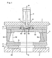
- Fig. 1 is a schematic sectional view showing a mold attaching/detaching apparatus in a tire vulcanizer, according to the embodiment.
- Fig. 2 is a sectional view taken along a line A-A in Fig. 1.
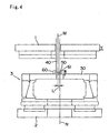
- Figs. 3 to 6 are each an explanatory view of an operation of a locking/unlocking means provided in the mold attaching/detaching apparatus.
- numeral 1 denotes a top plate
- 2 denotes a bottom plate.
- These top plate 1 and bottom plate 2 are supported so as to relatively move in a horizontal direction, and relatively move in a vertical direction at a vulcanizing position M.
- the top plate 1 is mounted to a main body cylinder (not shown), and at the vulcanizing position M, vertically moves up and down between an ascent position X (the position in Fig. 3) separated from a segmental mold 3, an opening position Y (the position in Figs. 4 and 5) for opening the segmental mold 3, and a closing position Z (the position in Fig. 6) for closing the segmental mold 3.
- the bottom plate 2 is mounted on a carriage (not shown), and with the segmental mold 3 placed thereon, the bottom plate 2 laterally move between the vulcanizing position M (the position in Figs. 5 and 6); an offset position N (the position in Figs. 3 and 4), which is horizontally shifted by a small distance L from the vulcanizing position M so as to be located immediately in front of the vulcanizing position M; and a mold replacement position (not shown).
- an upper platen 11 is provided, with an upper heat insulating plate 10 therebetween.
- a lower platen 21 is provided, with a lower heat insulating plate 20 therebetween, and has an annular pressurizing cylinder 22 incorporated therein.
- the segmental mold 3 includes an upper container plate 30 having an upper side-wall mold (not shown) mounted on the bottom surface thereof; a lower container plate 31 having a lower side-wall mold (not shown) mounted on the top surface thereof, and a plurality of divided segments 32 having a tread mold (not shown) mounted on the inner surface thereof, and expanding and contracting in radial directions.
- a container ring 33 having a tapered inner surface is fixed on the outer peripheral surface of the upper container plate 30 so as to slide with respect to the container ring 33 and upper container plate 30.
- the segments 32 perform expanding/contracting operations with an expansion/contraction device 4 mounted to the top plate 1.
- a fluid pressure cylinder (hydraulic cylinder) is used as the expansion/contraction device 4.
- the segmental mold 3 needs to be replaced in accordance with the size of a tire to be produced.
- locking/unlocking means is provided between the expansion/contraction device 4 and the upper container plate 30.
- the locking/unlocking means is constituted of a locking piece 50 formed at the front end of the cylinder rod 40 of the expansion/contraction device 4 so as to jut out outward along the circumference, and a receiving piece 61 formed in a receiving block 60 mounted to the upper container plate 30.
- the receiving block 60 has a long slotted hole 62 formed in the moving direction of the bottom plate 2, and the receiving piece 61 is formed at the upper edge on one side of the slotted hole 62 so as to jut out inward semi-arcuately.
- the locking piece 50 is formed so as to be engaged with the receiving piece 61, at the vulcanizing position M, and so as to be disengaged from the receiving piece 61, at the offset position N.
- the top plate 1 moves down to the opening position Y together with the liquid pressure cylinder serving as the expansion/contraction device 4.
- the front end of the cylinder rod 40 is inserted into the slotted hole 62 of the receiving block 60.
- the locking piece 50 and receiving piece 61 which serve as the locking/unlocking means, are not yet engaged with each other.
- the bottom plate 2 moves from the offset position N to the vulcanizing position M, and thereby the center of the top plate 1 and the center of the bottom plate 2 coincide with each other at the vulcanizing position M.
- the locking piece 50 horizontally moves to below the receiving piece 61 and is engaged with the receiving piece 61.
- the locking/unlocking means is formed so that a slight gap occurs between the locking piece 50 and receiving piece 61 in a mutual engaged state.
- the top plate 1 is lowered to the closing position Z, and the top plate 1 and upper container plate 30 are connected with fastening means such as bolts, thus completing connecting work for the mold.
- the vulcanization of a tire is performed in a state where, at the vulcanizing position M, the top plate 1 connected with the upper container plate 30 moves down from the opening position Y to the closing position Z, and the segmental mold 3 is held between the top plate 1 and bottom plate 2.
- a bladder (not shown) expanding and contracting under the supply/discharge of a heating fluid, and the bladder expanded by the supply of the heated fluid is pressed against the inner surface of a raw tire set inside the segmental mold 3, and heating is performed by the upper platen 11 and lower platen 21, whereby the vulcanization molding is performed.
- the insertion/withdrawal of the tire in/from the segmental mold 3 is performed by opening and closing the segmental mold 3 while expanding and contracting the segment 32, by raising and lowering the top plate 1 between the opening position Y and closing position Z, as well as expanding and contracting the expansion/contraction device 4, in a mutual engaged state between the locking piece 50 and receiving piece 61, which serve as the locking/unlocking means.
- the top plate and bottom plate can relatively move in the horizontal direction and that they can relatively move in the vertical direction at the vulcanizing position.
- the top plate may be caused to move in the horizontal direction
- the bottom plate may be caused to move up and down.
- expansion/contraction device a fluid pressure cylinder or motor-operated cylinder is usually employed.
- the expansion/contraction device is not limited to such a cylinder, but may include any one performing an expanding/contracting operation.
- the engaging means is not limited to a locking piece and receiving piece as in the embodiment, but may include any ones that are configured so as to be engaged with each other in a state where the top plate and bottom plate coincide with each other at the vulcanizing position, and so as to be disengaged from each other at the offset position where the top plate or bottom plate is shifted from the vulcanizing position in the horizontal direction.
- the mold attaching/detaching apparatus in a tire vulcanizer has locking/unlocking means that performs engagement and disengagement utilizing the relative movement between the top plate and bottom plate of the tire vulcanizer. Therefore, there is no need to incorporate a rotational mechanism into the expanding/contracting device, unlike the conventional locking/unlocking means using a bayonet mechanism. This simplifies the structure and operation of the locking/unlocking means, and produces an effect of allowing an inexpensive construction.
Landscapes
- Engineering & Computer Science (AREA)
- Mechanical Engineering (AREA)
- Physics & Mathematics (AREA)
- Health & Medical Sciences (AREA)
- Oral & Maxillofacial Surgery (AREA)
- Thermal Sciences (AREA)
- Moulds For Moulding Plastics Or The Like (AREA)
- Heating, Cooling, Or Curing Plastics Or The Like In General (AREA)
Abstract
Description
- The present invention relates to a mold attaching/detaching apparatus in a tire vulcanizer.
- With the trend of tire width toward smaller size, the main stream of a mold in a tire vulcanizer is shifting from a two-piece mold that is vertically divided into two pieces, to a segmental mold.
- This segmental mold includes an upper container plate, a lower container plate, and a plurality of divided segments expanding and contracting in radial directions.
- An expansion/contraction device for expanding and contracting the segments of the segmental mold is provided to a top plate. These segments are adapted to expand and contract due to an expanding/contracting operation of the expansion/contraction device and the inner structure of the segmental mold.
- The mold in a tire vulcanizer needs to be replaced in accordance with the size of a tire to be produced. For this purpose, locking/unlocking means is provided between the expansion/contraction device and the upper container plate of the segmental mold.
- As locking/unlocking means provided between the expansion/contraction device and the upper container plate of the segmental mold, for example, locking/unlocking means using a bayonet mechanism as disclosed in Japanese Examined Patent Application Publication No. 5-62046, has hitherto been known.
- The locking/unlocking means using this bayonet mechanism includes a bayonet lock provided to the upper container plate and a bayonet claw provided to the expansion/contraction device, and has a configuration in which the bayonet claw is engaged with and disengaged from the bayonet lock.
- However, as before, the locking/unlocking means using the bayonet mechanism needs to rotate its bayonet claw provided to the expansion/contraction device to engage with and disengage from the bayonet lock.
- Originally, the function of the expansion/contraction device is to expand and contract the segments of the segmental mold by expanding/contracting operations thereof, and hence, the expansion/contraction device has only to have a structure allowing expanding/contracting operations. However, the conventional locking/unlocking means is required to incorporate a rotational mechanism for rotating the bayonet claw into the expansion/contraction device.
- In the arrangement incorporating the locking/unlocking means into the expansion/contraction device thereof as described above, a problem has occurred in that the structure thereof becomes complicated correspondingly, as well as the locking/unlocking operation also becomes complicated since the locking/unlocking entails a rotational operation.
- The present invention has been made for solving the above-described conventional problem. The object of the present invention is to provide a mold attaching/detaching apparatus in a tire vulcanizer, having locking/unlocking means configured to perform an engagement and disengagement by utilizing a relative movement between the top plate and bottom plate of the tire vulcanizer in a horizontal direction, and thereby capable of being inexpensively constructed by simplifying the structure and operation of the locking/unlocking means.
- To solve the above-described problems, the present invention provides a mold attaching/detaching apparatus (Claim 1) in a tire vulcanizer. Herein, the tire vulcanizer includes a top plate and a bottom plate relatively moving in a horizontal direction, and relatively moving in a vertical direction at a vulcanizing position; a segmental mold that includes an upper container plate, a lower container plate, and a plurality of divided segments expanding and contracting in radial directions, and that is replaceably placed on the bottom plate; an expansion/contraction device mounted to the top plate, and expanding and contracting,the segments of the segmental mold; a locking/unlocking means provided between the expansion/contraction device and the upper container plate; and the segmental mold being held between the top plate and the bottom plate to perform vulcanization at the vulcanizing position, and opened and closed while expanding and contracting the segments by raising and lowering the top plate and operating an expansion/contraction device, in an engaged state of the locking/unlocking means. Herein, the locking/unlocking means is configured so as to perform an engagement in a state where the center of the top plate and the center of the bottom plate coincide with each other at a vulcanizing position by the relative movement between the top plate and the bottom plate in a horizontal direction, and so as to perform disengagement at an offset position shifted from the vulcanizing position in the horizontal direction.
- Also, in the mold attaching/detaching apparatus in a tire vulcanizer, set forth in Claim 1, the mold attaching/detaching apparatus (Claim 2) in a tire vulcanizer is arranged so that the locking/unlocking means is configured so as to include a locking piece provided to the expansion/contraction device and a receiving piece provided to an upper mold of the segmental mold, and so as to horizontally move to below the receiving piece to be engaged with the receiving piece, at the vulcanizing position, and horizontally move from below the receiving piece to be disengaged from the receiving piece, at the offset position.
-
- Fig. 1 is a schematic sectional view showing an embodiment of a mold attaching/detaching apparatus in a tire vulcanizer.
- Fig. 2 is a sectional view taken along a line A-A in Fig. 1.
- Fig. 3 is an explanatory view of an operation of a locking/unlocking means provided in the mold attaching/detaching apparatus.
- Fig. 4 is an explanatory view of an operation of the locking/unlocking means provided in the mold attaching/detaching apparatus.
- Fig. 5 is an explanatory view of an operation of the locking/unlocking means provided in the mold attaching/detaching apparatus.
- Fig. 6 is an explanatory view of an operation of the locking/unlocking means provided in the mold attaching/detaching apparatus.
- Hereinafter, an embodiment according to the present invention will be described with respect to the drawings. The specific construction of the present invention is not limited by the embodiment described below.
- Fig. 1 is a schematic sectional view showing a mold attaching/detaching apparatus in a tire vulcanizer, according to the embodiment. Fig. 2 is a sectional view taken along a line A-A in Fig. 1. Figs. 3 to 6 are each an explanatory view of an operation of a locking/unlocking means provided in the mold attaching/detaching apparatus.
- In these figures, numeral 1 denotes a top plate, 2 denotes a bottom plate. These top plate 1 and
bottom plate 2 are supported so as to relatively move in a horizontal direction, and relatively move in a vertical direction at a vulcanizing position M. - In this embodiment, the top plate 1 is mounted to a main body cylinder (not shown), and at the vulcanizing position M, vertically moves up and down between an ascent position X (the position in Fig. 3) separated from a
segmental mold 3, an opening position Y (the position in Figs. 4 and 5) for opening thesegmental mold 3, and a closing position Z (the position in Fig. 6) for closing thesegmental mold 3. - The
bottom plate 2 is mounted on a carriage (not shown), and with thesegmental mold 3 placed thereon, thebottom plate 2 laterally move between the vulcanizing position M (the position in Figs. 5 and 6); an offset position N (the position in Figs. 3 and 4), which is horizontally shifted by a small distance L from the vulcanizing position M so as to be located immediately in front of the vulcanizing position M; and a mold replacement position (not shown). - On the undersurface of the top plate 1, an upper platen 11 is provided, with an upper
heat insulating plate 10 therebetween. On the top surface of thebottom surface 2, alower platen 21 is provided, with a lowerheat insulating plate 20 therebetween, and has an annular pressurizingcylinder 22 incorporated therein. - The
segmental mold 3 includes anupper container plate 30 having an upper side-wall mold (not shown) mounted on the bottom surface thereof; alower container plate 31 having a lower side-wall mold (not shown) mounted on the top surface thereof, and a plurality ofdivided segments 32 having a tread mold (not shown) mounted on the inner surface thereof, and expanding and contracting in radial directions. - On the outer peripheral surface of the
upper container plate 30, acontainer ring 33 having a tapered inner surface is fixed. Thesegments 32 are supported on theupper container plate 30 so as to slide with respect to thecontainer ring 33 andupper container plate 30. - The
segments 32 perform expanding/contracting operations with an expansion/contraction device 4 mounted to the top plate 1. In this embodiment, a fluid pressure cylinder (hydraulic cylinder) is used as the expansion/contraction device 4. - With a
cylinder rod 40 of the expansion/contraction device 4 engaged with theupper container plate 30, thesegments 32 opens and closes due to expanding/contracting operations of thecylinder rod 40 and the inner structure of the segmental mold 3 (detailed descriptions are omitted). - The
segmental mold 3 needs to be replaced in accordance with the size of a tire to be produced. For this purpose, locking/unlocking means is provided between the expansion/contraction device 4 and theupper container plate 30. - The locking/unlocking means is constituted of a
locking piece 50 formed at the front end of thecylinder rod 40 of the expansion/contraction device 4 so as to jut out outward along the circumference, and areceiving piece 61 formed in areceiving block 60 mounted to theupper container plate 30. - The
receiving block 60 has a longslotted hole 62 formed in the moving direction of thebottom plate 2, and thereceiving piece 61 is formed at the upper edge on one side of theslotted hole 62 so as to jut out inward semi-arcuately. Thelocking piece 50 is formed so as to be engaged with thereceiving piece 61, at the vulcanizing position M, and so as to be disengaged from thereceiving piece 61, at the offset position N. - Specifically, when a new replaced
segmental mold 3 is connected to the tire vulcanizer, in a state where the top plate 1 is located at the ascent position as shown in Fig. 3, thebottom plate 2 on which thesegmental mold 3 is placed moves from the mold replacement position to the offset position N. - Next, as shown in Fig. 4, the top plate 1 moves down to the opening position Y together with the liquid pressure cylinder serving as the expansion/
contraction device 4. At this time, the front end of thecylinder rod 40 is inserted into theslotted hole 62 of thereceiving block 60. In this state, however, thelocking piece 50 and receivingpiece 61, which serve as the locking/unlocking means, are not yet engaged with each other. - Then, as shown in Fig. 5, the
bottom plate 2 moves from the offset position N to the vulcanizing position M, and thereby the center of the top plate 1 and the center of thebottom plate 2 coincide with each other at the vulcanizing position M. By this movement, in theslotted hole 62, thelocking piece 50 horizontally moves to below thereceiving piece 61 and is engaged with thereceiving piece 61. - Herein, the locking/unlocking means is formed so that a slight gap occurs between the
locking piece 50 and receivingpiece 61 in a mutual engaged state. - Even though there occurs a gap between the
locking piece 50 and receivingpiece 61 in this way, it does not interfere with operations of the expansion/contraction device 4. The provision of this gap enables thelocking piece 50 to smoothly perform a horizontal movement between the offset position N and vulcanizing position M. - After the liquid pressure cylinder serving as the expansion/
contraction device 4 and theupper container plate 30 of thesegmental mold 3 have been connected with each other in this manner, as shown in Fig. 6, the top plate 1 is lowered to the closing position Z, and the top plate 1 andupper container plate 30 are connected with fastening means such as bolts, thus completing connecting work for the mold. - When replacing the mold, in order to release the connection between the
segmental mold 3 and tire vulcanizer, the reverse operations (Fig. 6 → Fig. 3) of the foregoing is to be performed. - The vulcanization of a tire is performed in a state where, at the vulcanizing position M, the top plate 1 connected with the
upper container plate 30 moves down from the opening position Y to the closing position Z, and thesegmental mold 3 is held between the top plate 1 andbottom plate 2. In this situation, inside thesegmental mold 3, there is provided a bladder (not shown) expanding and contracting under the supply/discharge of a heating fluid, and the bladder expanded by the supply of the heated fluid is pressed against the inner surface of a raw tire set inside thesegmental mold 3, and heating is performed by the upper platen 11 andlower platen 21, whereby the vulcanization molding is performed. - The insertion/withdrawal of the tire in/from the
segmental mold 3 is performed by opening and closing thesegmental mold 3 while expanding and contracting thesegment 32, by raising and lowering the top plate 1 between the opening position Y and closing position Z, as well as expanding and contracting the expansion/contraction device 4, in a mutual engaged state between thelocking piece 50 and receivingpiece 61, which serve as the locking/unlocking means. - In the present invention, it is essential only that the top plate and bottom plate can relatively move in the horizontal direction and that they can relatively move in the vertical direction at the vulcanizing position. Hence, contrary to the above-described embodiment, the top plate may be caused to move in the horizontal direction, and the bottom plate may be caused to move up and down.
- As the expansion/contraction device, a fluid pressure cylinder or motor-operated cylinder is usually employed. However, the expansion/contraction device is not limited to such a cylinder, but may include any one performing an expanding/contracting operation.
- Also, the engaging means is not limited to a locking piece and receiving piece as in the embodiment, but may include any ones that are configured so as to be engaged with each other in a state where the top plate and bottom plate coincide with each other at the vulcanizing position, and so as to be disengaged from each other at the offset position where the top plate or bottom plate is shifted from the vulcanizing position in the horizontal direction. Industrial Applicability
- As described above, the mold attaching/detaching apparatus in a tire vulcanizer, according to the present invention has locking/unlocking means that performs engagement and disengagement utilizing the relative movement between the top plate and bottom plate of the tire vulcanizer. Therefore, there is no need to incorporate a rotational mechanism into the expanding/contracting device, unlike the conventional locking/unlocking means using a bayonet mechanism. This simplifies the structure and operation of the locking/unlocking means, and produces an effect of allowing an inexpensive construction.
Claims (2)
- A mold attaching/detaching apparatus in a tire vulcanizer, the tire vulcanizer comprising:a top plate and a bottom plate relatively moving in a horizontal direction, and relatively moving in a vertical direction at a vulcanizing position;a segmental mold that includes an upper container plate, a lower container plate, and a plurality of divided segments expanding and contracting in radial directions, and that is replaceably placed on the bottom plate;an expansion/contraction device mounted to the top plate, and expanding and contracting the segments of the segmental mold;a locking/unlocking means provided between the expansion/contraction device and the upper container plate; andthe segmental mold being held between the top plate and the bottom plate to perform vulcanization at the vulcanizing position, and opened and closed while expanding and contracting the segments by raising and lowering the top plate and operating the expansion/contraction device, in an engaged state of the locking/unlocking means,wherein the locking/unlocking means is configured so as to perform an engagement in a state where the center of the top plate and the center of the bottom plate coincide with each other at the vulcanizing position by the relative movement between the top plate and the bottom plate in a horizontal direction, and so as to perform disengagement at an offset position where the top plate or the bottom plate is shifted from the vulcanizing position in the horizontal direction.
- The mold attaching/detaching apparatus according to Claim 1, wherein the locking/unlocking means comprising:a locking piece provided in the expansion/contraction device; anda receiving piece provided to an upper mold of the segmental mold,wherein the locking/unlocking means is configured so as to horizontally move to below the receiving piece to be engaged with the receiving piece, at the vulcanizing position, and so as to horizontally move from below the receiving piece to be disengaged from the receiving piece, at the offset position.
Applications Claiming Priority (2)
| Application Number | Priority Date | Filing Date | Title |
|---|---|---|---|
| JP2003121408A JP4291612B2 (en) | 2003-04-25 | 2003-04-25 | Mold attaching / detaching device for tire vulcanizer |
| PCT/JP2004/006040 WO2004101250A1 (en) | 2003-04-25 | 2004-04-26 | Mold-attaching/detaching device in tire-vulcanizing machine |
Publications (3)
| Publication Number | Publication Date |
|---|---|
| EP1637304A1 true EP1637304A1 (en) | 2006-03-22 |
| EP1637304A4 EP1637304A4 (en) | 2007-05-30 |
| EP1637304B1 EP1637304B1 (en) | 2008-12-10 |
Family
ID=33447087
Family Applications (1)
| Application Number | Title | Priority Date | Filing Date |
|---|---|---|---|
| EP04729544A Expired - Lifetime EP1637304B1 (en) | 2003-04-25 | 2004-04-26 | Mold-attaching/detaching device in tire-vulcanizing machine |
Country Status (7)
| Country | Link |
|---|---|
| US (1) | US7371060B2 (en) |
| EP (1) | EP1637304B1 (en) |
| JP (1) | JP4291612B2 (en) |
| KR (1) | KR100674346B1 (en) |
| CN (1) | CN100496935C (en) |
| DE (1) | DE602004018314D1 (en) |
| WO (1) | WO2004101250A1 (en) |
Cited By (2)
| Publication number | Priority date | Publication date | Assignee | Title |
|---|---|---|---|---|
| WO2009109184A2 (en) | 2008-03-04 | 2009-09-11 | Harburg-Freudenberger Maschinenbau Gmbh | Method and device for mounting forms |
| FR2951401A1 (en) * | 2009-10-20 | 2011-04-22 | Michelin Soc Tech | VULCANIZATION PRESS |
Families Citing this family (7)
| Publication number | Priority date | Publication date | Assignee | Title |
|---|---|---|---|---|
| FR2966075B1 (en) * | 2010-10-19 | 2012-12-14 | Michelin Soc Tech | DEVICE FOR VULCANIZING A TIRE COMPRISING AN INTERNAL RECOVERY ENCLOSURE |
| KR101329215B1 (en) * | 2011-12-16 | 2013-11-14 | 한국타이어 주식회사 | Tire vulcanizing container |
| JP5705762B2 (en) | 2012-02-03 | 2015-04-22 | 三菱重工マシナリーテクノロジー株式会社 | Tire vulcanizer and tire vulcanizer |
| US9346228B2 (en) * | 2014-07-09 | 2016-05-24 | Mcneil & Nrm, Inc. | Segmented mold operator |
| CN105563713B (en) * | 2016-02-26 | 2017-12-19 | 浙江荣升机械有限公司 | A kind of upper die shoe plate guider for tyre vulcanizer |
| DE112016007514B4 (en) | 2016-12-12 | 2022-01-27 | Rocky-Ichimaru Co., Ltd. | Heat insulation plate, heat insulation structure for tire vulcanizer and vulcanization method for green tire |
| CN116330541B (en) * | 2023-04-28 | 2026-02-10 | 舟山尚轮科技有限公司 | A quick mold changing device and method for use on a hydraulic vulcanizing machine |
Family Cites Families (9)
| Publication number | Priority date | Publication date | Assignee | Title |
|---|---|---|---|---|
| JPS56118019U (en) | 1980-02-09 | 1981-09-09 | ||
| IT1176523B (en) * | 1984-08-01 | 1987-08-18 | Pirelli | IMPROVEMENTS IN THE VULCANIZATION PRESSES |
| JPH069796Y2 (en) | 1988-06-09 | 1994-03-16 | 三菱電線工業株式会社 | Mold equipment |
| JPH0625314Y2 (en) | 1989-12-08 | 1994-07-06 | 株式会社松田製作所 | Mold attaching / detaching device in injection molding machine |
| JPH0629815U (en) | 1992-09-25 | 1994-04-19 | 株式会社神戸製鋼所 | Mold clamp device for tire vulcanizer |
| JPH0847928A (en) * | 1994-06-03 | 1996-02-20 | Mitsubishi Heavy Ind Ltd | Split mold device for vulcanization of tire |
| EP0712704A3 (en) * | 1994-11-16 | 1996-11-13 | Mitsubishi Heavy Ind Ltd | Tire vulcanizing mold assembly |
| JP4007714B2 (en) | 1998-04-17 | 2007-11-14 | 株式会社ブリヂストン | Tire vulcanizing apparatus and mold changing method thereof |
| US6292993B1 (en) * | 1998-04-17 | 2001-09-25 | Bridgestone Corporation | Vulcanizing machine with segmented mold |
-
2003
- 2003-04-25 JP JP2003121408A patent/JP4291612B2/en not_active Expired - Fee Related
-
2004
- 2004-04-26 KR KR1020057019686A patent/KR100674346B1/en not_active Expired - Lifetime
- 2004-04-26 US US10/554,465 patent/US7371060B2/en not_active Expired - Lifetime
- 2004-04-26 CN CNB2004800104749A patent/CN100496935C/en not_active Expired - Fee Related
- 2004-04-26 WO PCT/JP2004/006040 patent/WO2004101250A1/en not_active Ceased
- 2004-04-26 EP EP04729544A patent/EP1637304B1/en not_active Expired - Lifetime
- 2004-04-26 DE DE602004018314T patent/DE602004018314D1/en not_active Expired - Fee Related
Cited By (7)
| Publication number | Priority date | Publication date | Assignee | Title |
|---|---|---|---|---|
| WO2009109184A2 (en) | 2008-03-04 | 2009-09-11 | Harburg-Freudenberger Maschinenbau Gmbh | Method and device for mounting forms |
| WO2009109184A3 (en) * | 2008-03-04 | 2009-11-12 | Harburg-Freudenberger Maschinenbau Gmbh | Method and device for mounting forms |
| FR2951401A1 (en) * | 2009-10-20 | 2011-04-22 | Michelin Soc Tech | VULCANIZATION PRESS |
| WO2011048131A1 (en) * | 2009-10-20 | 2011-04-28 | Societe De Technologie Michelin | Vulcanizing press |
| CN102712151A (en) * | 2009-10-20 | 2012-10-03 | 米其林企业总公司 | Pressurized vulcanizer |
| US8500430B2 (en) | 2009-10-20 | 2013-08-06 | Compagnie Generale Des Etablissements Michelin | Vulcanizing press |
| CN102712151B (en) * | 2009-10-20 | 2014-09-03 | 米其林企业总公司 | Pressurized vulcanizer |
Also Published As
| Publication number | Publication date |
|---|---|
| US20070009624A1 (en) | 2007-01-11 |
| CN1832837A (en) | 2006-09-13 |
| US7371060B2 (en) | 2008-05-13 |
| CN100496935C (en) | 2009-06-10 |
| EP1637304B1 (en) | 2008-12-10 |
| DE602004018314D1 (en) | 2009-01-22 |
| JP4291612B2 (en) | 2009-07-08 |
| WO2004101250A1 (en) | 2004-11-25 |
| KR20060003018A (en) | 2006-01-09 |
| EP1637304A4 (en) | 2007-05-30 |
| JP2004345086A (en) | 2004-12-09 |
| KR100674346B1 (en) | 2007-01-24 |
Similar Documents
| Publication | Publication Date | Title |
|---|---|---|
| US7371060B2 (en) | Mold-attaching/detaching device in tire-vulcanizing machine | |
| EP1923190B1 (en) | Tire vulcanizing apparatus | |
| US5165939A (en) | Vulcanization press having two molds operated separately from each other, in particular for vehicle tires | |
| CN109529434B (en) | But quick replacement's sewage filter screen | |
| JPH02107408A (en) | Standing well post type central mechanism for tire press | |
| JPH059133Y2 (en) | ||
| JPH05131453A (en) | Centering mechanism, of tire vulcanizing machine | |
| CN109689321B (en) | Tire vulcanizing device | |
| JP4134137B2 (en) | Tire vulcanizer | |
| JP4134138B2 (en) | Tire vulcanizer | |
| JP4191352B2 (en) | Container for tire mold | |
| US6273698B1 (en) | Tire vulcanizing system | |
| KR20080038257A (en) | Tire vulcanizer | |
| JP3354752B2 (en) | Tire vulcanizing mold assembly | |
| US5690970A (en) | Split mold opening/closing device for a tire vulcanizer | |
| JP3085833B2 (en) | Tire vulcanizing mold | |
| JPH0562046B2 (en) | ||
| CN102717456A (en) | Integrally heating huge radial wire cord off-the-road tire vulcanizing machine | |
| CN103862596A (en) | Novel nondestructive segmental mould for radial retractable tire | |
| CN203726675U (en) | Novel radial opening and closing tyre lossless segment mould | |
| CN113439015B (en) | Mold container device and tire vulcanizing machine | |
| KR20120060557A (en) | Vulcanizing apparatus for vehicle tire | |
| JPS63288719A (en) | Tire unloading device of tire vulcanizer | |
| CN107901461A (en) | Vulcanized tyre cooler and cooling means | |
| JP2001322126A (en) | Central mechanism of tire vulcanizing machine |
Legal Events
| Date | Code | Title | Description |
|---|---|---|---|
| PUAI | Public reference made under article 153(3) epc to a published international application that has entered the european phase |
Free format text: ORIGINAL CODE: 0009012 |
|
| 17P | Request for examination filed |
Effective date: 20051025 |
|
| AK | Designated contracting states |
Kind code of ref document: A1 Designated state(s): DE FR IT TR |
|
| DAX | Request for extension of the european patent (deleted) | ||
| RBV | Designated contracting states (corrected) |
Designated state(s): DE FR IT TR |
|
| A4 | Supplementary search report drawn up and despatched |
Effective date: 20070504 |
|
| 17Q | First examination report despatched |
Effective date: 20071004 |
|
| GRAP | Despatch of communication of intention to grant a patent |
Free format text: ORIGINAL CODE: EPIDOSNIGR1 |
|
| GRAS | Grant fee paid |
Free format text: ORIGINAL CODE: EPIDOSNIGR3 |
|
| GRAA | (expected) grant |
Free format text: ORIGINAL CODE: 0009210 |
|
| AK | Designated contracting states |
Kind code of ref document: B1 Designated state(s): DE FR IT TR |
|
| REF | Corresponds to: |
Ref document number: 602004018314 Country of ref document: DE Date of ref document: 20090122 Kind code of ref document: P |
|
| PGFP | Annual fee paid to national office [announced via postgrant information from national office to epo] |
Ref country code: DE Payment date: 20090428 Year of fee payment: 6 Ref country code: FR Payment date: 20090417 Year of fee payment: 6 Ref country code: IT Payment date: 20090423 Year of fee payment: 6 Ref country code: TR Payment date: 20090408 Year of fee payment: 6 |
|
| PLBE | No opposition filed within time limit |
Free format text: ORIGINAL CODE: 0009261 |
|
| STAA | Information on the status of an ep patent application or granted ep patent |
Free format text: STATUS: NO OPPOSITION FILED WITHIN TIME LIMIT |
|
| 26N | No opposition filed |
Effective date: 20090911 |
|
| REG | Reference to a national code |
Ref country code: FR Ref legal event code: ST Effective date: 20101230 |
|
| PG25 | Lapsed in a contracting state [announced via postgrant information from national office to epo] |
Ref country code: DE Free format text: LAPSE BECAUSE OF NON-PAYMENT OF DUE FEES Effective date: 20101103 |
|
| PG25 | Lapsed in a contracting state [announced via postgrant information from national office to epo] |
Ref country code: IT Free format text: LAPSE BECAUSE OF NON-PAYMENT OF DUE FEES Effective date: 20100426 |
|
| PG25 | Lapsed in a contracting state [announced via postgrant information from national office to epo] |
Ref country code: FR Free format text: LAPSE BECAUSE OF NON-PAYMENT OF DUE FEES Effective date: 20100430 |
|
| PG25 | Lapsed in a contracting state [announced via postgrant information from national office to epo] |
Ref country code: TR Free format text: LAPSE BECAUSE OF NON-PAYMENT OF DUE FEES Effective date: 20100426 |