EP1642694A1 - Méthode et appareil pour la coupe de matériaux élastomériques - Google Patents
Méthode et appareil pour la coupe de matériaux élastomériques Download PDFInfo
- Publication number
- EP1642694A1 EP1642694A1 EP20050108880 EP05108880A EP1642694A1 EP 1642694 A1 EP1642694 A1 EP 1642694A1 EP 20050108880 EP20050108880 EP 20050108880 EP 05108880 A EP05108880 A EP 05108880A EP 1642694 A1 EP1642694 A1 EP 1642694A1
- Authority
- EP
- European Patent Office
- Prior art keywords
- cutting
- laminate
- anvil
- blade
- cut
- Prior art date
- Legal status (The legal status is an assumption and is not a legal conclusion. Google has not performed a legal analysis and makes no representation as to the accuracy of the status listed.)
- Withdrawn
Links
- 238000005520 cutting process Methods 0.000 title claims abstract description 83
- 238000000034 method Methods 0.000 title claims abstract description 10
- 239000000463 material Substances 0.000 title description 5
- 230000003014 reinforcing effect Effects 0.000 claims description 8
- 230000001154 acute effect Effects 0.000 claims 1
- 230000002787 reinforcement Effects 0.000 abstract description 11
- 239000002131 composite material Substances 0.000 abstract description 6
- 230000007246 mechanism Effects 0.000 description 14
- 229920001971 elastomer Polymers 0.000 description 5
- 230000008901 benefit Effects 0.000 description 4
- 239000000806 elastomer Substances 0.000 description 4
- 238000004519 manufacturing process Methods 0.000 description 2
- 238000013459 approach Methods 0.000 description 1
- 239000011324 bead Substances 0.000 description 1
- 125000000484 butyl group Chemical group [H]C([*])([H])C([H])([H])C([H])([H])C([H])([H])[H] 0.000 description 1
- 238000010276 construction Methods 0.000 description 1
- 238000005516 engineering process Methods 0.000 description 1
- 239000000835 fiber Substances 0.000 description 1
- 238000010438 heat treatment Methods 0.000 description 1
- 239000002184 metal Substances 0.000 description 1
- 238000012986 modification Methods 0.000 description 1
- 230000004048 modification Effects 0.000 description 1
- 239000012779 reinforcing material Substances 0.000 description 1
- 230000032258 transport Effects 0.000 description 1
Images


Classifications
-
- B—PERFORMING OPERATIONS; TRANSPORTING
- B26—HAND CUTTING TOOLS; CUTTING; SEVERING
- B26D—CUTTING; DETAILS COMMON TO MACHINES FOR PERFORATING, PUNCHING, CUTTING-OUT, STAMPING-OUT OR SEVERING
- B26D3/00—Cutting work characterised by the nature of the cut made; Apparatus therefor
- B26D3/003—Cutting work characterised by the nature of the cut made; Apparatus therefor specially adapted for cutting rubber
-
- B—PERFORMING OPERATIONS; TRANSPORTING
- B26—HAND CUTTING TOOLS; CUTTING; SEVERING
- B26D—CUTTING; DETAILS COMMON TO MACHINES FOR PERFORATING, PUNCHING, CUTTING-OUT, STAMPING-OUT OR SEVERING
- B26D1/00—Cutting through work characterised by the nature or movement of the cutting member or particular materials not otherwise provided for; Apparatus or machines therefor; Cutting members therefor
- B26D1/01—Cutting through work characterised by the nature or movement of the cutting member or particular materials not otherwise provided for; Apparatus or machines therefor; Cutting members therefor involving a cutting member which does not travel with the work
- B26D1/04—Cutting through work characterised by the nature or movement of the cutting member or particular materials not otherwise provided for; Apparatus or machines therefor; Cutting members therefor involving a cutting member which does not travel with the work having a linearly-movable cutting member
- B26D1/045—Cutting through work characterised by the nature or movement of the cutting member or particular materials not otherwise provided for; Apparatus or machines therefor; Cutting members therefor involving a cutting member which does not travel with the work having a linearly-movable cutting member for thin material, e.g. for sheets, strips or the like
-
- B—PERFORMING OPERATIONS; TRANSPORTING
- B26—HAND CUTTING TOOLS; CUTTING; SEVERING
- B26D—CUTTING; DETAILS COMMON TO MACHINES FOR PERFORATING, PUNCHING, CUTTING-OUT, STAMPING-OUT OR SEVERING
- B26D7/00—Details of apparatus for cutting, cutting-out, stamping-out, punching, perforating, or severing by means other than cutting
- B26D7/01—Means for holding or positioning work
- B26D7/018—Holding the work by suction
-
- B—PERFORMING OPERATIONS; TRANSPORTING
- B26—HAND CUTTING TOOLS; CUTTING; SEVERING
- B26D—CUTTING; DETAILS COMMON TO MACHINES FOR PERFORATING, PUNCHING, CUTTING-OUT, STAMPING-OUT OR SEVERING
- B26D7/00—Details of apparatus for cutting, cutting-out, stamping-out, punching, perforating, or severing by means other than cutting
- B26D7/08—Means for treating work or cutting member to facilitate cutting
- B26D7/086—Means for treating work or cutting member to facilitate cutting by vibrating, e.g. ultrasonically
-
- B—PERFORMING OPERATIONS; TRANSPORTING
- B26—HAND CUTTING TOOLS; CUTTING; SEVERING
- B26D—CUTTING; DETAILS COMMON TO MACHINES FOR PERFORATING, PUNCHING, CUTTING-OUT, STAMPING-OUT OR SEVERING
- B26D9/00—Cutting apparatus combined with punching or perforating apparatus or with dissimilar cutting apparatus
-
- B—PERFORMING OPERATIONS; TRANSPORTING
- B29—WORKING OF PLASTICS; WORKING OF SUBSTANCES IN A PLASTIC STATE IN GENERAL
- B29D—PRODUCING PARTICULAR ARTICLES FROM PLASTICS OR FROM SUBSTANCES IN A PLASTIC STATE
- B29D30/00—Producing pneumatic or solid tyres or parts thereof
- B29D30/06—Pneumatic tyres or parts thereof (e.g. produced by casting, moulding, compression moulding, injection moulding, centrifugal casting)
- B29D30/38—Textile inserts, e.g. cord or canvas layers, for tyres; Treatment of inserts prior to building the tyre
- B29D30/46—Cutting textile inserts to required shape
-
- B—PERFORMING OPERATIONS; TRANSPORTING
- B26—HAND CUTTING TOOLS; CUTTING; SEVERING
- B26D—CUTTING; DETAILS COMMON TO MACHINES FOR PERFORATING, PUNCHING, CUTTING-OUT, STAMPING-OUT OR SEVERING
- B26D1/00—Cutting through work characterised by the nature or movement of the cutting member or particular materials not otherwise provided for; Apparatus or machines therefor; Cutting members therefor
- B26D1/01—Cutting through work characterised by the nature or movement of the cutting member or particular materials not otherwise provided for; Apparatus or machines therefor; Cutting members therefor involving a cutting member which does not travel with the work
- B26D1/04—Cutting through work characterised by the nature or movement of the cutting member or particular materials not otherwise provided for; Apparatus or machines therefor; Cutting members therefor involving a cutting member which does not travel with the work having a linearly-movable cutting member
-
- B—PERFORMING OPERATIONS; TRANSPORTING
- B26—HAND CUTTING TOOLS; CUTTING; SEVERING
- B26D—CUTTING; DETAILS COMMON TO MACHINES FOR PERFORATING, PUNCHING, CUTTING-OUT, STAMPING-OUT OR SEVERING
- B26D11/00—Combinations of several similar cutting apparatus
-
- B—PERFORMING OPERATIONS; TRANSPORTING
- B26—HAND CUTTING TOOLS; CUTTING; SEVERING
- B26D—CUTTING; DETAILS COMMON TO MACHINES FOR PERFORATING, PUNCHING, CUTTING-OUT, STAMPING-OUT OR SEVERING
- B26D3/00—Cutting work characterised by the nature of the cut made; Apparatus therefor
- B26D3/08—Making a superficial cut in the surface of the work without removal of material, e.g. scoring, incising
-
- B—PERFORMING OPERATIONS; TRANSPORTING
- B26—HAND CUTTING TOOLS; CUTTING; SEVERING
- B26D—CUTTING; DETAILS COMMON TO MACHINES FOR PERFORATING, PUNCHING, CUTTING-OUT, STAMPING-OUT OR SEVERING
- B26D7/00—Details of apparatus for cutting, cutting-out, stamping-out, punching, perforating, or severing by means other than cutting
- B26D7/08—Means for treating work or cutting member to facilitate cutting
- B26D7/10—Means for treating work or cutting member to facilitate cutting by heating
-
- B—PERFORMING OPERATIONS; TRANSPORTING
- B26—HAND CUTTING TOOLS; CUTTING; SEVERING
- B26D—CUTTING; DETAILS COMMON TO MACHINES FOR PERFORATING, PUNCHING, CUTTING-OUT, STAMPING-OUT OR SEVERING
- B26D7/00—Details of apparatus for cutting, cutting-out, stamping-out, punching, perforating, or severing by means other than cutting
- B26D7/20—Cutting beds
-
- B—PERFORMING OPERATIONS; TRANSPORTING
- B29—WORKING OF PLASTICS; WORKING OF SUBSTANCES IN A PLASTIC STATE IN GENERAL
- B29D—PRODUCING PARTICULAR ARTICLES FROM PLASTICS OR FROM SUBSTANCES IN A PLASTIC STATE
- B29D30/00—Producing pneumatic or solid tyres or parts thereof
- B29D30/06—Pneumatic tyres or parts thereof (e.g. produced by casting, moulding, compression moulding, injection moulding, centrifugal casting)
- B29D30/38—Textile inserts, e.g. cord or canvas layers, for tyres; Treatment of inserts prior to building the tyre
- B29D30/46—Cutting textile inserts to required shape
- B29D2030/466—Cutting the textile inserts between cords
-
- Y—GENERAL TAGGING OF NEW TECHNOLOGICAL DEVELOPMENTS; GENERAL TAGGING OF CROSS-SECTIONAL TECHNOLOGIES SPANNING OVER SEVERAL SECTIONS OF THE IPC; TECHNICAL SUBJECTS COVERED BY FORMER USPC CROSS-REFERENCE ART COLLECTIONS [XRACs] AND DIGESTS
- Y10—TECHNICAL SUBJECTS COVERED BY FORMER USPC
- Y10T—TECHNICAL SUBJECTS COVERED BY FORMER US CLASSIFICATION
- Y10T83/00—Cutting
- Y10T83/748—With work immobilizer
- Y10T83/7487—Means to clamp work
- Y10T83/7493—Combined with, peculiarly related to, other element
-
- Y—GENERAL TAGGING OF NEW TECHNOLOGICAL DEVELOPMENTS; GENERAL TAGGING OF CROSS-SECTIONAL TECHNOLOGIES SPANNING OVER SEVERAL SECTIONS OF THE IPC; TECHNICAL SUBJECTS COVERED BY FORMER USPC CROSS-REFERENCE ART COLLECTIONS [XRACs] AND DIGESTS
- Y10—TECHNICAL SUBJECTS COVERED BY FORMER USPC
- Y10T—TECHNICAL SUBJECTS COVERED BY FORMER US CLASSIFICATION
- Y10T83/00—Cutting
- Y10T83/748—With work immobilizer
- Y10T83/7487—Means to clamp work
- Y10T83/754—Clamp driven by yieldable means
-
- Y—GENERAL TAGGING OF NEW TECHNOLOGICAL DEVELOPMENTS; GENERAL TAGGING OF CROSS-SECTIONAL TECHNOLOGIES SPANNING OVER SEVERAL SECTIONS OF THE IPC; TECHNICAL SUBJECTS COVERED BY FORMER USPC CROSS-REFERENCE ART COLLECTIONS [XRACs] AND DIGESTS
- Y10—TECHNICAL SUBJECTS COVERED BY FORMER USPC
- Y10T—TECHNICAL SUBJECTS COVERED BY FORMER US CLASSIFICATION
- Y10T83/00—Cutting
- Y10T83/869—Means to drive or to guide tool
- Y10T83/8821—With simple rectilinear reciprocating motion only
- Y10T83/8822—Edge-to-edge of sheet or web [e.g., traveling cutter]
Definitions
- This invention relates to a method and an apparatus for cutting elastomeric materials at low skive angles, and cutting a multilayered elastomeric composite including one or more layers containing reinforcing materials.
- the pneumatic tire has been fabricated as a laminate structure of generally toroidal shape having beads, a tread, belt reinforcement and a carcass.
- the manufacturing technologies employed for the most part involve the successive assembling of multiple tire components onto a tire building drum wherein each tire component is cut to length and spliced on the drum.
- a typical tire may comprise about six splices spaced about the tire.
- Recent advances in the first stage of tire subassembly construction involve the utilization of a single unvulcanized laminated structure, such as described in US-B-5,762,740 and 5,746,101. Instead of multiple tire components being applied to a tire building drum in a successive manner, a single laminate structure is cut to the appropriate length and then applied to the tire building drum, wherein the ends of the laminated structure are spliced together. It is desired then that the ends of the laminated structure be cut at a low skive angle, because it allows for a butt splice or a splice wherein a few cords overlap, resulting in a stronger splice.
- the laminate structure includes a reinforcement layer such as reinforced ply containing closely spaced reinforcement cords
- a reinforcement layer such as reinforced ply containing closely spaced reinforcement cords
- the cut must be made between the parallel-aligned reinforcing cords, without cutting through any of the reinforcement cords. This can be an extremely difficult task to accomplish, because the reinforcement cords are typically very closely spaced, on the order of 30 cords/inch.
- An ideal cutting method and apparatus should also be able to make cuts at low angles relative to the plane of the elastomeric sheet being cut in a rapid and reliable manner.
- Axial and “axially” means the lines or directions that are parallel to the axis of rotation of the tire.
- “Circumferential” means lines or directions extending along the perimeter of the surface of the annular tread perpendicular to the axial direction; it can also refer to the direction of the sets of adjacent circular curves whose radii define the axial curvature of the tread as viewed in cross section.
- Core means one of the reinforcement strands, including fibers, which are used to reinforce the plies.
- Ply means a cord-reinforced layer of elastomer-coated, radially deployed or otherwise parallel cords.
- Ring and radially mean directions radially toward or away from the axis of rotation of the tire.
- “Skive” or “skive angle” refers to the cutting angle of a knife with respect to the material being cut; the skive angle is measured with respect to the plane of the flat material being cut.
- Laminate structure means an unvulcanized structure made of one or more layers of tire or elastomer components such as the innerliner, sidewalls, and optional ply layer.
- a strip of elastomeric composite or laminate structure 1 to be cut by the method and apparatus of the invention is shown in Figures 1-3.
- the cutting apparati described herein are not limited to cutting laminate, as other materials such as ply or gum components may also be used.
- the laminate 1 has a width W and an indefinite length designated by the L direction.
- the dotted line 3 shows the location or path of a lateral cut that is to be made across the width of the laminate 1.
- the path 3 can be perpendicular to the length L of the laminate or at an oblique angle across the width W. If the laminate 1 has one or more reinforcement layers of parallel cords 22 that are similarly oriented, then it is preferred that the cutting path 3 be oriented relative to the cord 22 path.
- the laminate 1 may include various components used in the manufacture of tires.
- Figures 2 and 3 illustrate one example of a laminate 1 having an optional ply layer 20 comprised of cords 22 and having a width less than the laminate width W, inserts 30, shoulder gum strips 40, a liner 50, a pair of chaffer strips 60, and a pair of sidewall components 70.
- other components used in tire making may also be included.
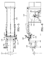
- a first embodiment of a cutting device 100 of the invention is shown in Figures 4-6.
- the cutting device 100 functions to cut the laminate into strips of a desired length so that each end is cut at a desired skive angle.
- the skived ends are then joined together, wherein a carcass for a radial ply pneumatic tire, such as described in more detail below, is manufactured.
- One advantage to the invention is that the resulting butt splice formed is very strong, and due to the fact that there is only one splice, a more stronger, uniform tire is formed.
- the cutting device 100 may include an optional conveyor system, an anvil system, a gum cutter system and an optional ply cutter system, all of which are described in greater detail, below.
- the laminate stock is typically mounted on a large roll 132 which may be rotatably mounted on a spindle 134 adjacent the feed conveyor belt 110.
- the laminate 1 is mounted so that the gum layers are face down on the conveyor belt, while the ply layer is face up.
- the invention is not limited to this configuration as the machinery could be reversed.
- the cutting device 100 comprises a feed conveyor 110 for advancing the laminate stock 1 to the cutting section 120 of the cutting device 100.
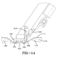
- the feed conveyor 110 has a retractable nose 112 that translates away from the anvil prior to the cutting operation.
- the feed conveyor 110 has side supports 116 mounted in side rails 118 to allow the nose 112 of the feed conveyor to slide forward and aft, so that the nose is retracted out of the way of the cutter mechanism so that it can translate downward, as shown in Figure 8.
- Actuator arm 114 connected to the top mounted rail 115 of feed conveyor 110 retracts in order to move the nose of the conveyor.
- a downstream conveyor 130 transports the laminate strip away from the cutting device 100, generally towards a tire building drum 133.
- the conveyor system 110, 130 may further include a length sensor (not shown) located on or adjacent the second conveyor belt, which communicates with a control system 200 (not shown) to advance the laminate past the cutting line on the anvil of the cutting device 100 until the desired length to be cut has been reached.
- a length sensor located on or adjacent the second conveyor belt, which communicates with a control system 200 (not shown) to advance the laminate past the cutting line on the anvil of the cutting device 100 until the desired length to be cut has been reached.
- the anvil assembly 140 comprises a rectangular shaped bar having a length suitable for cutting across the width of the laminate.
- the longitudinal axis of the anvil may be oriented at a ninety degree angle to the width of the laminate.
- both the anvil 142 and the first and second stage cutting devices 144, 146 may be slidably mounted on vertical side rails 148 so that the cutter system 144,146 can translate downward until the lower surface of the anvil 142 contacts the laminate, after the nose of the feed conveyor system has translated away from the anvil. Hydraulic cylinder 149 moves the cutter system up and down the tracks of support rails 148.
- the anvil lower surface is divided into three sections.
- the leading edge section 150 is angled at angle, typically a desired skive angle, in the range of 3-8 degrees.
- the anvil lower surface has a middle section 152 that may be flat or slightly angled, and a third or rear section 154 that is angled typically in the range of 5 to 15 degrees.
- Each of the three anvil sections has a plurality of closely spaced vacuum holes 156 connected to one or more sources of vacuum.
- One or more rows of vacuum holes that are perpendicular to the longitudinal axis of the anvil may be each grouped into a zone, wherein each zone has an independently controlled vacuum source.
- the anvil has interior segmented cavities, wherein each cavity is connected to a row of vacuum holes at the anvil surface and its own independently controlled vacuum line (see Figure 21). Utilizing independently controlled zones allows for the adjustment of the laminate stock width so that suction is not lost because of holes that are not in contact with the laminate.
- each of the sections 150, 152, 154 may also be desired to have independent control of the vacuum holes in each of the sections 150, 152, 154 so that the vacuum of each of the sections may be turned on or off, independent of each other.
- the first stage cutting system 144 is utilized to cut through only the gum layers of the laminate or gum/elastomer stock not containing ply.
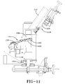
- the cutting blade 160 may be an ultrasonic blade. As shown in Figures 22-23, the blade 160 is preferably wedge-shaped and has a flat cutting edge 162, wherein the entire cutting edge 162 is a node. As shown in Figure 11, the blade 160 is mounted on a holder 170 that can adjust the skive angle ⁇ , angle of attack ⁇ as well as vertical and horizontal adjustments. The blade holder 170 is slidably mounted on a lower support bar 172 so that the blade 162 can traverse across the anvil lower surface 142 cutting the gum components of the laminate, from one side to the other.
- a pulley system, a ball screw or any other conventional translating means may be used to translate the blade holder and blade.
- a translation servo system 174 may be used to track the position of the blade across the width of the laminate. The speed of the translation may be preprogrammed into a controller (not shown) so that the speed can be varied across the width of the anvil.
- the leading edge 162 of the blade 160 is set at a desired skive angle ⁇ in relation to the plane of the gum surface of the laminate and the anvil lower surface.
- the gum ends will have a skive angle ⁇ .
- the leading edge of the blade 162 is also rotated about the longitudinal axis of the anvil an attack angle angle ⁇ in the range of 10 to 60 degrees depending upon the thickness of the laminate stock, generally 20- 30 degrees.
- a calibration block 180 may be utilized.
- the calibration block comprises a block having an angled calibration surface 182 wherein the flat edges 184 of the ultrasonic blade may be placed flush against the calibration surface in order to adjust the skive angle ⁇ and angle ⁇ to the desired settings.
- the calibration surface may have angular notations on it for easy adjustment.
- the leading edge corner 162 of the blade 160 is aligned with the vertice of the angular markings on the surface of the calibration block.
- the alignment of the edge corner 186 of the blade with the vertice may be the system calibration point or "zero".
- the calibration block is preferably mounted adjacent to the end of the anvil assembly for ease of use.
- the calibration block may also be used as the "home” for the servosystem.
- the term "home” could include the blade settings of skive angle ⁇ and angle ⁇ , the x and y (gap height or distance from the blade to the anvil).
- the blade also preferably has a height adjustment mechanism 161.
- the blade holder is mounted upon a servo driven vertical adjustment mechanism such as a linear actuator or ball screw and rail assembly 161 that allows the adjustment of the height of the blade (the distance between the blade and the anvil) as the blade traverses the width of the laminate stock.
- the height of the blade can be programmed to vary as the blade traverses the width of the ply. It is preferred that the height of the blade be adjusted slightly greater than the ply thickness as the blade approaches the ply edge, so that the blade does not snag a ply.
- the blade height is preferably lowered closer to the surface of the laminate, so that the blade skims closely against the ply, removing all innerliner butyl or gum from the ply surface.
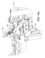
- the secondary cutting system 146 for cutting the ply may be utilized.
- the second stage cutting system 146 includes a cutting mechanism 200 and a retractable pull down bar 300.
- the cutting mechanism 200 is mounted over the anvil on support rail 210 via support arm 212, on the ply side of the laminate.
- the cutting mechanism 200 further comprises a guide member 214 which is mounted parallel to the anvil.
- the cutting means 220 is a divided blade having two sides 222a, 222b which split apart after the cutting means is plunged through the center of the ply.
- Belts 224 traverse blades apart, cutting the ply.
- the invention is not limited to a split blade, as other cutting means such as a single knife may also be used.
- Blades 222 or cutting means 220 rest upon a hot plate preferably spring loaded and heated to a temperature suitable for cutting ply stock.
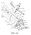
- the cutting system 146 further comprises a retractable pull down bar 300.
- the pull down bar 300 is rotatably mounted to the anvil, wherein the bar is situated near the anvil leading edge surface as shown in Figure 8b.
- the pull down bar may be actuated into engagement with the ply via hydraulic arm 310.
- the pull down bar functions to pull the ply away from the leading edge portion 150 and middle portion 152 of the lower surface of the anvil, leaving the ply only in contact with the rear portion 154 of the anvil.
- the skived gum component flap opens up, allowing the cutting means 220 to be in position to plunge through and cut only the ply.
- Tension of the ply can be adjusted by running the feed conveyor belt slightly forward before or during the pulldown of the ply to prevent excessive tension and stretching.
- the cutting system may cut laminate as described above, or conventional elastomer stock such as used in making tires.
- the laminate or stock 1 to be cut is typically mounted on a large roll onto a spindle adjacent the feed conveyor belt.
- the laminate is fed onto the conveyor belt so that the ply layer is face up and the gum layers are face down.
- the leading edge of the laminate is advanced forward onto the feed conveyor belt to the cut conveyor belt until the desired length is reached at the cutting edge of the anvil.
- Sensors mounted on or adjacent the cut conveyor belt detects when the desired length to be cut has been reached, so that the cutting line of the laminate is positioned on the cutting edge of the anvil.
- the nose of the feed conveyor is translated away from the cutting line, and the anvil assembly is lowered until the laminate contacts the lower surface of the anvil. More preferably, the anvil assembly is lowered past the plane of the conveyor upper surface until the laminate is in slight tension, and the laminate wraps around the lower surfaces of the anvil, as shown in Figure 8a.
- the anvil vacuum zones are turned on all three surfaces so that the laminate is held in place by the suction from the anvil surface. The suction, wrap and tension all function together to securely hold the laminate in place for the cut.
- the cutting blade 160 is next traversed along the cutting edge of the anvil, cutting only through the gum layers at a desired angle ⁇ , typically in the range of 5 to 45 degrees.
- the cutting blade edge may also be rotated away from the longitudinal axis of the anvil an angle of attack ⁇ , typically in the range of 20 to 45 degrees.
- the cutting blade is preferably an ultrasonic cutter with a bevel edged blade.
- the blade holder may be mounted on a linear actuator and servo system such as a linear screw (not shown) and rail assembly 161 as shown in Figure 11 that allows for vertical adjustment of the distance or gap between the blade and the anvil lower surface while the blade traverses across the width of the anvil.
- the vertical height adjustment allows for the varying thicknesses of the ply.
- the vertical height adjustment also allows the blade to have an increased gap just prior to the ply edge, and to decrease the gap after the blade passes the ply edge so that the cords are not inadvertently snagged.
- the blade angle settings may be checked periodically to ensure the proper blade angles are maintained.
- a calibration block mounted near the anvil may be used to ensure the proper blade angles are set.
- the calibration block has an angled surface to match the desired angle of the anvil surface and to position the blade at the desired angle of attack ⁇ and cutting angle ⁇
- the blade is positioned adjacent the angled calibration surface of the calibration block.
- To adjust the cutting angle ⁇ the blade is adjusted until the leading edge of the blade is flush with the calibration block outer surface.
- To adjust the angle of attack ⁇ the operator rotates the blade until the cutting surface of the blade is at the desired angle displayed on the face of the calibration block.
- a flap of gum is formed.
- the tension in the laminate as well as the wrap of the laminate about the anvil ensures that the flap stays open and does not reseal.
- the laminate is first positioned for the secondary cut through the ply.
- the vacuum is turned off in the leading edge section 150 and middle section 152 except for the rear section where the vacuum is turned on.
- the tension on the laminate is loosened by driving the feed conveyor belt forward slightly in the range typically of 0.25 to 1 inch.
- the pull down bar is actuated so that it pulls the laminate down and away from the anvil leading edge portion and the middle portion, while the laminate remains suctioned to the rear surface of the anvil.
- the pull down bar opens up the flap to provide clearance for the secondary plunge cutter.
- the laminate is now in position for the plunge cut.
- One advantage to using a pull down bar is that the laminate is moved away from the anvil so that the ply cords can "float" or move slightly during the cut.
- Another advantage of the pull down bar is that the skived flap of gum rubber is opened to provided adequate clearance for a plunging blade.
- the ply cutting apparatus is then actuated so that the ply cutter plunges through the ply layer in the exposed ply adjacent the flap of gum (flap opening).
- the ply cutter preferably plunges from the ply side of the laminate, which reduces the possibility of damage to the flap of gum.
- the ply cutter is heated and is a two piece blade that makes the cut in the center of the ply. The two piece blade plunges into the ply and then separates into two blades.
- other blade configurations may also be used such as a single blade that traverses across the ply.
- One way of heating the ply cutter is to utilize a heated block located on the apparatus.
- the heated block is made of conductive metal that is heated to a temperature in the range of 288°C to 316°C (550 to 600 Deg F).
- the base of the blade rests against the heated block.
- the base of the blade has to be heated to 550-600 degrees F in order to drive the blade tip temperature to about 149°C (300 degrees F).
- a spring loaded hot plate is utilized, wherein the blade tip rests on the hot surface when not in use.
- the spring loaded hot plate surface is heated to 149°C to 177°C (300-350 degrees F).
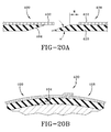
- a first end 400 has skived gum layer 404 and an overhang of ply 402.
- the second end 408 of the segment has a skived gum layer 410 and an offset in the ply 412 from the free end 408, typically about a half of an inch.
- the ends 400 and 408 are then joined together forming an offset splice.
- the offset splice 420 is illustrated in Figure 20b, wherein one or more cords overlap in forming the splice, and the skived ends of the gum layer are mated together, forming a strong splice.
- the splice may also be formed without any cord overlap.
Landscapes
- Engineering & Computer Science (AREA)
- Mechanical Engineering (AREA)
- Life Sciences & Earth Sciences (AREA)
- Forests & Forestry (AREA)
- Textile Engineering (AREA)
- Tyre Moulding (AREA)
- Nonmetal Cutting Devices (AREA)
Applications Claiming Priority (1)
| Application Number | Priority Date | Filing Date | Title |
|---|---|---|---|
| US61509204P | 2004-10-01 | 2004-10-01 |
Publications (1)
| Publication Number | Publication Date |
|---|---|
| EP1642694A1 true EP1642694A1 (fr) | 2006-04-05 |
Family
ID=35500645
Family Applications (1)
| Application Number | Title | Priority Date | Filing Date |
|---|---|---|---|
| EP20050108880 Withdrawn EP1642694A1 (fr) | 2004-10-01 | 2005-09-26 | Méthode et appareil pour la coupe de matériaux élastomériques |
Country Status (5)
| Country | Link |
|---|---|
| US (2) | US20060070504A1 (fr) |
| EP (1) | EP1642694A1 (fr) |
| JP (1) | JP4754923B2 (fr) |
| CN (1) | CN100509316C (fr) |
| BR (1) | BRPI0504137A (fr) |
Cited By (5)
| Publication number | Priority date | Publication date | Assignee | Title |
|---|---|---|---|---|
| DE202006006208U1 (de) * | 2006-04-13 | 2007-08-23 | Kiersch Composite Gmbh | Schneidvorrichtung |
| EP2633988A1 (fr) * | 2012-03-02 | 2013-09-04 | Continental Reifen Deutschland GmbH | Procédé de sectionnement d'un composant de pneu constitué d'un élastomère ayant une épaisseur de matériau fine sur les côtés et s'étendant en pointe |
| CN106758120A (zh) * | 2017-03-02 | 2017-05-31 | 杭州凯秀纺织有限公司 | 用于围巾纺织的面料分割装置 |
| CN111172733A (zh) * | 2020-01-10 | 2020-05-19 | 山东滨津纺织科技有限公司 | 玻璃纤维憎水布 |
| CN119159621A (zh) * | 2024-11-21 | 2024-12-20 | 湖南大用智能科技有限公司 | 果实切片机的校准机构、校准方法以及果实切片机 |
Families Citing this family (17)
| Publication number | Priority date | Publication date | Assignee | Title |
|---|---|---|---|---|
| DE102009020621B4 (de) * | 2009-05-09 | 2011-03-03 | Fecken-Kirfel Gmbh & Co. Kg | Folienschälverfahren |
| US9027815B2 (en) | 2010-08-31 | 2015-05-12 | Corning Incorporated | Apparatus and method for making glass sheet with improved sheet stability |
| MX341871B (es) * | 2011-06-17 | 2016-09-05 | Pirelli | Proceso y aparato para construir llantas para ruedas de vehiculo. |
| NL2007058C2 (nl) * | 2011-07-06 | 2013-01-08 | Vmi Holland Bv | Samenstel en werkwijze voor het vervaardigen van een groene band. |
| EP2771179B1 (fr) * | 2011-10-26 | 2015-10-07 | Pirelli Tyre S.p.A. | Procédé et appareil pour construire des pneumatiques auto-obturateurs pour roues de véhicules |
| JP6347964B2 (ja) * | 2014-02-26 | 2018-06-27 | 株式会社ブリヂストン | タイヤの分別方法 |
| CN104290109B (zh) * | 2014-09-17 | 2016-01-20 | 张家港市兰航机械有限公司 | 硅胶柱的切割装置 |
| NL2014552B1 (en) * | 2015-03-30 | 2017-01-06 | Vmi Holland Bv | Cutting station for a tire building machine. |
| CN104972494B (zh) * | 2015-06-30 | 2017-01-11 | 重庆市金盾橡胶制品有限公司 | 一种胎面垫布分离切割机构 |
| CN104972495B (zh) * | 2015-06-30 | 2017-01-04 | 重庆市金盾橡胶制品有限公司 | 一种橡胶轮胎胎面切割装置 |
| CN104973394B (zh) * | 2015-06-30 | 2017-04-05 | 重庆市金盾橡胶制品有限公司 | 一种橡胶轮胎胎面垫布分离切割装置 |
| JP2018171669A (ja) | 2017-03-31 | 2018-11-08 | ブラザー工業株式会社 | 切断装置 |
| CN107398931B (zh) * | 2017-07-24 | 2019-02-19 | 长乐晶尚设计有限公司 | 一种移动式橡胶自动切割设备 |
| WO2019051186A1 (fr) * | 2017-09-08 | 2019-03-14 | Technical Rubber Company, Inc. | Appareil et procédé de réduction de dimension de pneumatique |
| CN110405977B (zh) * | 2019-07-19 | 2021-10-12 | 合肥智慧殿机械设计有限公司 | 一种薄膜干料包夹的弧削弹性体棱面的侧向进料造粒机 |
| JP7736457B2 (ja) * | 2021-05-31 | 2025-09-09 | 株式会社ディスコ | シート貼着装置 |
| CN115179357B (zh) * | 2022-06-27 | 2024-06-25 | 太原理工大学 | 一种输送带钢丝绳芯分离装置 |
Citations (4)
| Publication number | Priority date | Publication date | Assignee | Title |
|---|---|---|---|---|
| US3895990A (en) * | 1971-07-30 | 1975-07-22 | Rheinische Braunkohlenw Ag | Process for joining strips of belt along their lengthwise running side edges |
| US4867434A (en) * | 1987-07-09 | 1989-09-19 | Bridgestone Corporation | Apparatus for grasping ends of belt-like members |
| WO2000051810A1 (fr) * | 1999-03-03 | 2000-09-08 | The Goodyear Tire & Rubber Company | Formation de joints d'epissure pour materiaux elastomeres |
| EP1262288A2 (fr) * | 2001-06-01 | 2002-12-04 | The Goodyear Tire & Rubber Company | Procédé ainsi que dispositif pour découper des matériaux elastomères |
Family Cites Families (22)
| Publication number | Priority date | Publication date | Assignee | Title |
|---|---|---|---|---|
| US3232159A (en) * | 1963-09-24 | 1966-02-01 | Parker Hannifin Corp | Portable hose cut-off means |
| DE2805870C2 (de) | 1978-02-11 | 1985-08-14 | Metzeler Kautschuk GmbH, 8000 München | Vorrichtung zum Querschneiden von Gummibahnen |
| JPS58203033A (ja) * | 1982-05-24 | 1983-11-26 | Bridgestone Corp | 未加硫ゴムシ−ト切断装置 |
| US4610750A (en) * | 1985-04-05 | 1986-09-09 | Branson Ultrasonics Corporation | Ultrasonic cut and seal apparatus |
| US4560427A (en) * | 1984-12-03 | 1985-12-24 | Branson Ultrasonics Corporation | Ultrasonic seal and cut method and apparatus |
| NL8800077A (nl) * | 1988-01-14 | 1989-08-01 | Vmi Epe Holland | Inrichting voor het doorsnijden van een strook ongevulcaniseerde rubber. |
| US4987808A (en) * | 1988-06-20 | 1991-01-29 | Bridgestone/Firestone, Inc. | Tubular sleeve handling and cut-off system |
| US4920495A (en) * | 1988-07-15 | 1990-04-24 | Gfm Holdings Ag | Sheet cutting machine |
| IT1239347B (it) | 1990-02-26 | 1993-10-20 | Pirelli | Apparecchiatura per il taglio a misura di fasce battistrada per pneumatici di veicoli,e procedimento di taglio attuato da detta apparecchiatura |
| DE4130269C2 (de) * | 1990-09-13 | 1996-05-23 | Toshiba Machine Co Ltd | Verfahren und Vorrichtung zum Herstellen laminierter Prepreg-Teile |
| US5265508A (en) * | 1990-10-31 | 1993-11-30 | General Tire, Inc. | Ultrasonic cutting system for stock material |
| DE4142723A1 (de) * | 1991-12-21 | 1993-07-01 | Continental Ag | Verfahren und vorrichtung zum ablaengen einer materialbahn aus reifenaufbaumaterial |
| JP2624606B2 (ja) * | 1992-08-04 | 1997-06-25 | 住友ゴム工業株式会社 | ラバーコンポーネントカッター |
| US5350470A (en) * | 1993-11-30 | 1994-09-27 | Bridgestone Corporation | Method of forming tire bead assembly |
| US5638732A (en) * | 1994-09-02 | 1997-06-17 | The Goodyear Tire & Rubber Company | Apparatus for cutting of elastomeric materials |
| CA2145794A1 (fr) * | 1995-01-05 | 1996-07-06 | James Alfred Ii Benzing | Methode et appareil pour couper un stratifie d'elastomere renforce d'un cable |
| US5762740A (en) * | 1995-01-05 | 1998-06-09 | The Goodyear Tire & Rubber Company | Method for building a laminate from an assembly of tire components to form a casing |
| JP3736824B2 (ja) * | 1997-09-30 | 2006-01-18 | キヤノンファインテック株式会社 | 記録媒体裁断装置 |
| DE69814478T2 (de) | 1998-10-20 | 2004-02-19 | The Goodyear Tire & Rubber Co., Akron | Verfahren sowie vorrichtung zum schneiden von elastomeren materialien |
| US6592704B1 (en) * | 1999-03-03 | 2003-07-15 | The Goodyear Tire & Rubber Company | Forming splice joints for elastomeric materials |
| US6790301B2 (en) * | 2001-10-15 | 2004-09-14 | The Goodyear Tire And Rubber Company | Method and apparatus for making a tread-belt assembly |
| US7455002B2 (en) * | 2004-12-23 | 2008-11-25 | The Goodyear Tire & Rubber Company | Method for cutting elastomeric materials and the article made by the method |
-
2005
- 2005-07-07 US US11/176,160 patent/US20060070504A1/en not_active Abandoned
- 2005-09-26 EP EP20050108880 patent/EP1642694A1/fr not_active Withdrawn
- 2005-09-29 BR BRPI0504137 patent/BRPI0504137A/pt not_active IP Right Cessation
- 2005-09-30 CN CNB200510107101XA patent/CN100509316C/zh not_active Expired - Fee Related
- 2005-10-03 JP JP2005290044A patent/JP4754923B2/ja not_active Expired - Fee Related
-
2009
- 2009-03-18 US US12/406,134 patent/US8794117B2/en not_active Expired - Fee Related
Patent Citations (4)
| Publication number | Priority date | Publication date | Assignee | Title |
|---|---|---|---|---|
| US3895990A (en) * | 1971-07-30 | 1975-07-22 | Rheinische Braunkohlenw Ag | Process for joining strips of belt along their lengthwise running side edges |
| US4867434A (en) * | 1987-07-09 | 1989-09-19 | Bridgestone Corporation | Apparatus for grasping ends of belt-like members |
| WO2000051810A1 (fr) * | 1999-03-03 | 2000-09-08 | The Goodyear Tire & Rubber Company | Formation de joints d'epissure pour materiaux elastomeres |
| EP1262288A2 (fr) * | 2001-06-01 | 2002-12-04 | The Goodyear Tire & Rubber Company | Procédé ainsi que dispositif pour découper des matériaux elastomères |
Cited By (6)
| Publication number | Priority date | Publication date | Assignee | Title |
|---|---|---|---|---|
| DE202006006208U1 (de) * | 2006-04-13 | 2007-08-23 | Kiersch Composite Gmbh | Schneidvorrichtung |
| EP2633988A1 (fr) * | 2012-03-02 | 2013-09-04 | Continental Reifen Deutschland GmbH | Procédé de sectionnement d'un composant de pneu constitué d'un élastomère ayant une épaisseur de matériau fine sur les côtés et s'étendant en pointe |
| CN106758120A (zh) * | 2017-03-02 | 2017-05-31 | 杭州凯秀纺织有限公司 | 用于围巾纺织的面料分割装置 |
| CN106758120B (zh) * | 2017-03-02 | 2023-03-14 | 杭州凯秀纺织有限公司 | 用于围巾纺织的面料分割装置 |
| CN111172733A (zh) * | 2020-01-10 | 2020-05-19 | 山东滨津纺织科技有限公司 | 玻璃纤维憎水布 |
| CN119159621A (zh) * | 2024-11-21 | 2024-12-20 | 湖南大用智能科技有限公司 | 果实切片机的校准机构、校准方法以及果实切片机 |
Also Published As
| Publication number | Publication date |
|---|---|
| US20090173199A1 (en) | 2009-07-09 |
| CN1796063A (zh) | 2006-07-05 |
| US8794117B2 (en) | 2014-08-05 |
| CN100509316C (zh) | 2009-07-08 |
| JP2006103328A (ja) | 2006-04-20 |
| JP4754923B2 (ja) | 2011-08-24 |
| US20060070504A1 (en) | 2006-04-06 |
| BRPI0504137A (pt) | 2006-05-23 |
Similar Documents
| Publication | Publication Date | Title |
|---|---|---|
| US8794117B2 (en) | Apparatus for cutting elastomeric materials | |
| EP1674252A1 (fr) | Procédé pour découper des matériaux élastomériques et segment ainsi réalisé | |
| US8561511B2 (en) | Anvil with vacuum width adjustment | |
| EP0619170B1 (fr) | Procédé et dispositif pour la fabrication d'une feuille caoutchoutée renforcée par fils | |
| US7811399B2 (en) | Tire component cutter apparatus and method of cutting | |
| US5746102A (en) | Method for cutting a cord reinforced elastomeric laminate | |
| US20080149258A1 (en) | Tire assembly applier with cutter mechanism | |
| US4608890A (en) | Method of cutting elastomeric material | |
| EP1262288B1 (fr) | Procédé pour découper des matériaux elastomères | |
| US11951703B2 (en) | Process and apparatus for building tyres for vehicle wheels | |
| EP3144130B1 (fr) | Procédé d'assemblage de pli de carcasse de pneu et nappe de carcasse continue | |
| US20080149259A1 (en) | Tire assembly applier with cutter mechanism | |
| US6575064B2 (en) | Method and apparatus for cutting elastomeric materials | |
| EP1159123B1 (fr) | Formation de joints d'epissure pour materiaux elastomeres | |
| NZ207445A (en) | Fabric sheet cutting knife | |
| EP2946915B1 (fr) | Appareil d'assemblage de pli de carcasse de pneu et procédé | |
| NZ207444A (en) | Sheet material roller centering device |
Legal Events
| Date | Code | Title | Description |
|---|---|---|---|
| PUAI | Public reference made under article 153(3) epc to a published international application that has entered the european phase |
Free format text: ORIGINAL CODE: 0009012 |
|
| AK | Designated contracting states |
Kind code of ref document: A1 Designated state(s): AT BE BG CH CY CZ DE DK EE ES FI FR GB GR HU IE IS IT LI LT LU LV MC NL PL PT RO SE SI SK TR |
|
| AX | Request for extension of the european patent |
Extension state: AL BA HR MK YU |
|
| 17P | Request for examination filed |
Effective date: 20061005 |
|
| 17Q | First examination report despatched |
Effective date: 20061108 |
|
| AKX | Designation fees paid |
Designated state(s): DE ES FR |
|
| STAA | Information on the status of an ep patent application or granted ep patent |
Free format text: STATUS: THE APPLICATION IS DEEMED TO BE WITHDRAWN |
|
| 18D | Application deemed to be withdrawn |
Effective date: 20100206 |