EP1645491A2 - Radiator core support structure - Google Patents
Radiator core support structure Download PDFInfo
- Publication number
- EP1645491A2 EP1645491A2 EP05292086A EP05292086A EP1645491A2 EP 1645491 A2 EP1645491 A2 EP 1645491A2 EP 05292086 A EP05292086 A EP 05292086A EP 05292086 A EP05292086 A EP 05292086A EP 1645491 A2 EP1645491 A2 EP 1645491A2
- Authority
- EP
- European Patent Office
- Prior art keywords
- core support
- radiator core
- upper cover
- sides
- fan shroud
- Prior art date
- Legal status (The legal status is an assumption and is not a legal conclusion. Google has not performed a legal analysis and makes no representation as to the accuracy of the status listed.)
- Granted
Links
- 238000003780 insertion Methods 0.000 description 3
- 230000037431 insertion Effects 0.000 description 3
- 239000011347 resin Substances 0.000 description 3
- 229920005989 resin Polymers 0.000 description 3
- 239000002826 coolant Substances 0.000 description 2
- 238000001816 cooling Methods 0.000 description 2
- 230000007423 decrease Effects 0.000 description 2
- 239000002184 metal Substances 0.000 description 2
- 238000007664 blowing Methods 0.000 description 1
- 230000008878 coupling Effects 0.000 description 1
- 238000010168 coupling process Methods 0.000 description 1
- 238000005859 coupling reaction Methods 0.000 description 1
- 230000000694 effects Effects 0.000 description 1
- 238000005516 engineering process Methods 0.000 description 1
- 238000004519 manufacturing process Methods 0.000 description 1
- 239000000463 material Substances 0.000 description 1
- 230000004048 modification Effects 0.000 description 1
- 238000012986 modification Methods 0.000 description 1
- 230000002093 peripheral effect Effects 0.000 description 1
Images


Classifications
-
- B—PERFORMING OPERATIONS; TRANSPORTING
- B62—LAND VEHICLES FOR TRAVELLING OTHERWISE THAN ON RAILS
- B62D—MOTOR VEHICLES; TRAILERS
- B62D25/00—Superstructure or monocoque structure sub-units; Parts or details thereof not otherwise provided for
- B62D25/08—Front or rear portions
- B62D25/082—Engine compartments
- B62D25/084—Radiator supports
Definitions
- the present invention relates to a radiator core support structure for mounting a heat exchanger on a motor vehicle.
- a radiator core support structure for a motor vehicle is described in Japanese Patent Application Laid-open No. 2003-81135, which has an upper radiator core support extending in a lateral direction of a motor vehicle body, a lower radiator core support extending in parallel with the upper radiator core support, radiator core support sides fixing both end portions of the upper radiator core support and the lower radiator core support to each other, and a hood lock stay fixing center portions of the upper radiator core support and the lower radiator core support to each other.
- Japanese Patent Application Laid-open No. 2002-19638 discloses a technology on a radiator core support of a type in which the upper radiator core support is omitted from the first conventional structure described above.
- the heat exchanger can be inserted and fixed between both the radiator core support sides from the upper side of the radiator core support, but the overall stiffness of the radiator core support decreases, so that each part thereof needs to be formed with a large thickness to increase their stiffness. This causes a problem of increasing weight and a manufacturing cost.
- radiator core support since impact force generated in the event of a light crash of a motor vehicle acts on the radiator core support so as to open outward in the lateral direction of the vehicle body, the upper radiator core support serves as a beam member to prevent deformation of both the radiator core support sides outward in the lateral direction.
- radiator core supports of recent years are formed integrally using resin or metal, they require a lot of labor and cost to be repaired or replaced.
- the present invention is made to solve the above-described problems, and an object thereof is to provide a radiator core support structure which can provide excellent workability for mounting a heat exchanger on a radiator core support without causing decrease of the overall stiffness of the radiator core support.
- a radiator core support structure includes a lower radiator core support extending in a lateral direction of a motor vehicle body, radiator core support sides extending upward respectively from both end portions of the lower radiator core support, a fan shroud portion provided inside the lower radiator core support and both the radiator core support sides, and a radiator core support upper cover provided to cover at least an upper side between both the radiator core support sides, wherein the lower radiator core support, both the radiator core support sides, and the fan shroud portion are formed integrally, and the radiator core support upper cover is fixed detachably at least on upper portions of the radiator core support sides.
- the heat exchanger when the heat exchanger is assembled, the heat exchanger is inserted from an upper side between both the radiator core support sides and attached thereto in a state that the radiator core support upper cover is removed, and the radiator core support upper cover can be attached thereafter. Accordingly, the heat exchanger can be attached to the radiator core support simply within a small working space, because the heat changer does not need to be slanted when it is inserted between both the radiator core support sides.
- the overall stiffness of the radiator core support can be improved by the fan shroud portion and the radiator core support upper cover, and particularly, it is possible to prevent, in the event of a light crash of a motor vehicle, deformation of both the radiator core support sides to open outward in the vehicle width direction to thereby cause a crack/damage.
- radiator core support upper cover in a detachable manner, an operation of repairing or replacing the heat exchanger can be easily performed.
- the radiator core support structure further comprises a detachable hood lock stay fixing center portions of the radiator core support upper cover and the lower radiator core support to each other.
- the radiator core support upper cover is fixed detachably on an upper portion of the fan shroud portion.
- the radiator core support upper cover can be stably fixed to the fan shroud portion, and thereby increase the overall stiffness of the radiator core support.
- the radiator core support upper cover is fixed to the fan shroud portion and the radiator core support sides.
- the radiator core support upper cover can be stably fixed to the fan shroud portion and the radiator core support sides, and thereby increase the overall stiffness of the radiator core support.
- the radiator core support upper cover is fixed to the fan shroud portion and the radiator core support sides.
- the radiator core support upper cover is formed with attachment holes to fix mounting pins of the heat exchanger, and provided on a bottom face thereof with sandwiching portions to sandwich and fix tongue pieces of the fan shroud portion in a forward and back ward direction thereof.
- both the heat exchanger and the radiator core support cover can be appropriately fixed in a positioned state.
- the radiator core support structure of this embodiment has a radiator core support 1 mounted on a front side of a vehicle body, a heat exchanger 2 for cooling coolant and cooling medium, and a motor fan 3 for cooling the heat exchanger 3.
- the heat exchanger 2 and the motor fan 3 are fixed to the radiator core support 1, which will be described below in detail.
- the radiator core support 1 has a lower radiator core support 4 extending in a lateral direction of the vehicle body, two radiator core support sides 5 and 5 extending upward respectively from both end portions of the lower radiator core support, and a fan shroud portion 6 provided inside the lower radiator core support 4 and both the radiator core support sides 5 and 5.
- the lower radiator core support 4, the radiator core support sides 5 and 5 and the fan shroud portion 6 are integrally formed of resin.
- a radiator core support upper cover 7 shown in FIG. 4 is provided so as to couple both the radiator core support sides 5 and 5 to each other
- a hood lock stay 8 shown in FIG. 5 is provided so as to couple center portions of the radiator core support upper cover 7 and the lower radiator core support 4 to each other.
- the lower radiator core support 4 is formed to have a cross-section in shape of a letter of L or the like opening downward and rearward, and on a top face thereof, two attachment holes 4a and 4a are formed at positions corresponding to mounting pins P1 and P1, shown in FIG. 1, provided respectively on both ends of a lower side of the heat exchanger 2.
- two attachment holes 4b and 4b are formed at positions corresponding to attachment holes 8a and 8a of a lower portion of the hood lock stay 8.
- the radiator core support sides 5 and 5 are formed to have a cross section in a shape of a letter of C or the like opening rearward, and two side member attachment holes 5a and 5a for coupling not-shown side members and bumper stays are formed respectively therein.
- Two head lamp stays 5b and 5b for fixing and supporting not-shown head lamps are formed respectively in the vicinities of the side member attachment holes 5a and 5a in a state of projecting outward in the lateral direction.
- two attachment holes 5c and 5c are formed at positions corresponding to attachment holes 7e and 7e of the radiator core support upper cover 7.
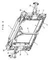
- the fan shroud portion 6 is formed integrally with and inside of the lower radiator core support 4 and both the radiator core support sides 5 and 5, thereby increasing the overall stiffness of the radiator core support 1.
- two openings 6a and 6a for accommodating a motor fan 3 are formed, and above the openings 6a and 6a, two attachment holes 6b and 6b are formed at positions corresponding to attachment holes 3a and 3a of the motor fan 3 as shown in FIG. 1.
- two attachment holes 6c are 6c are formed at positions corresponding to inserting projections 3b and 3b of the motor fan 3 as shown in FIG. 1.
- two attachment holes 6d and 6d are formed at positions corresponding to attachment holes 7a and 7a of the radiator core support upper cover 7, and also two tongue pieces 6e and 6e projecting upward in a plate shape are formed at positions corresponding to sandwiching portions 7f and 7f constituted of two pieces formed on a bottom face of the radiator core support upper cover 7.
- the radiator core support upper cover 7 has a main purpose of improving the design inside an engine room as well as preventing blowing back of hot air to the front side of the heat exchanger, and is formed of resin in a plate shape.
- the attachment holes 7a and 7a and the attachment holes 7e and 7e are formed, and two attachment holes 7b and 7b are formed at positions corresponding to mounting pins P2 and P2, as shown in FIG. 1, provided respectively on both ends of an upper side of the heat exchanger 2.
- two attachment holes 7c and 7c are formed at positions corresponding to attachment holes 8b and 8b on an upper portion of the hood lock stay 8.
- the sandwiching portions 7f and 7f are formed.
- the hood lock stay 8 is formed by press forming a metal plate, and on the upper portion thereof, the attachment holes 8b and 8b are formed, and three attachment holes 8c for fixing a not-shown hood lock stay are formed.
- two attachment holes 8a are 8a are formed on a lower portion of the hood lock stay 8.
- heat exchanger 2 of this embodiment there is adopted an integral-type heat exchanger formed integrally of a condenser core and a radiator core, which are arranged closely.
- the heat exchanger 2 When assembling a radiator core support structure, as shown in FIG. 1 and FIG. 6, the heat exchanger 2 is inserted in an upright state thereof from a top side between both the radiator core support sides 5 and 5, and the mounting pins P1 and P1 being inserted into lower mount bushes 9 are 9 are fixed to the attachment holes 4a and 4a of the lower radiator core support 4.
- the radiator core support upper cover 7 is placed from an upper side thereof, thereby fixing the mounting pins P2 and P2 in the attachment holes 7b and 7b of the radiator core support upper cover 7 via the upper mount bushes 10 and 10.
- screws B 1 and B 1 are inserted through the attachment holes 7a and 7a of the radiator core support upper cover 7 and the attachment holes 6d and 6d of the fan shroud portion and fixed therein, and screws B2 and B2 are inserted through the attachment holes 7e and 7e of the radiator core support upper cover 7 and the attachment holes 5c and 5c of both the radiator core support sides 5 and 5 and fixed therein, thereby mounting the radiator core support upper cover 7 and the heat exchanger 2 on the radiator core support 1.
- the attachment holes 7b and 7b of the radiator core support upper cover 7 fix the mounting pins P2 and P2 of the heat exchanger 2, and the two sandwiching portions 7f and 7f on the bottom face of the radiator core support upper cover 7 sandwich and fix the tongue pieces 6e and 6e of the fan shroud portion 6 in a forward and backward direction of the vehicle body respectively, so that both the heat exchanger 2 and the radiator core support upper cover 7 can be appropriately fixed in a positioned state.
- screws B4 and B4 are inserted through the attachment holes 8b and 8b of the hood lock stay 8 and the attachment holes 7c and 7c of the radiator core support upper cover 7 and fixed therein, and screws B5 and B5 are inserted through the attachment holes 8a and 8a of the hood lock stay 8 and the attachment holes 4b and 4b of the lower radiator core support 4 and fixed therein, thereby fixing the hood lock stay 8 onto the radiator core support 1 and completing the assembly of the radiator core support 1 as shown in FIG. 2.
- the radiator core support 1 constructed as above is, after not-shown peripheral members such as head lamps, a bumper stay, a bumper armature, and the others are attached, transported to an assembly factory of motor vehicles and mounted on a motor vehicle.
- radiator core support sides 5 and 5 In the event of a light crash of a motor vehicle, an impact force thereof acts on both the radiator core support sides 5 and 5 so as to open outward in the lateral direction of the vehicle body, but the fan shroud portion 6 formed integrally with and inside of both the radiator core support sides 5 and 5 and the lower radiator core support 4 and the radiator core support upper cover 7 coupled to the both of them serve as a beam member to prevent deformation of both the radiator core support sides 5 and 5 outward in the vehicle width direction. Therefore, a crack/damage on the radiator core support 1 can be prevented.
- the impact force transferred to the hood lock stay 8 can always be transferred to both the radiator core support sides 5 and 5 and the fan shroud portion 6 via the radiator core support upper cover 7, so that damaged portions are stopped at the hood lock stay 8 or the radiator core support upper cover 7 and thus the cost of fixing or replacing can be suppressed low.
- radiator core support upper cover 7 and the hood lock stay 8 are detachable from the radiator core support 1, maintainability inside the engine room is improved, and particularly, an operation of repairing or replacing the heat exchanger becomes simpler.
- the heat exchanger 2 when the heat exchanger 2 is assembled, the heat exchanger 2 is inserted from an upper side between both the radiator core support sides 5 and 5 and attached thereto in a state that the radiator core support upper cover 7 is removed, and the radiator core support upper cover 7 can be attached thereafter. Accordingly, the heat exchanger 2 can be attached to the radiator core support 1 simply within a small working space.
- the fan shroud portion 6 and the radiator core support upper cover 7 can improve the overall stiffness of the radiator core support while omitting an upper radiator core support, and particularly, deformation of both the radiator core support sides 5 and 5 outward in the lateral direction in the event of a light crash of a motor vehicle can be prevented.
- radiator core support upper cover 7 in a detachable manner, an operation of repairing or replacing the heat exchanger 2 can be easily performed.
- the radiator core support upper cover 7 and the upper portion of the fan shroud portion 6 are fixed to each other, the radiator core support upper cover 7 can be fixed stably, and moreover the overall stiffness of the radiator core support 1 can be improved.
- hood lock stay 8 and the radiator core support upper cover 7 can be determined appropriately.
Landscapes
- Engineering & Computer Science (AREA)
- Chemical & Material Sciences (AREA)
- Combustion & Propulsion (AREA)
- Transportation (AREA)
- Mechanical Engineering (AREA)
- Cooling, Air Intake And Gas Exhaust, And Fuel Tank Arrangements In Propulsion Units (AREA)
- Body Structure For Vehicles (AREA)
- Superstructure Of Vehicle (AREA)
Abstract
Description
- The present invention relates to a radiator core support structure for mounting a heat exchanger on a motor vehicle.
- Hitherto, a radiator core support structure for a motor vehicle is described in Japanese Patent Application Laid-open No. 2003-81135, which has an upper radiator core support extending in a lateral direction of a motor vehicle body, a lower radiator core support extending in parallel with the upper radiator core support, radiator core support sides fixing both end portions of the upper radiator core support and the lower radiator core support to each other, and a hood lock stay fixing center portions of the upper radiator core support and the lower radiator core support to each other.
- Also, Japanese Patent Application Laid-open No. 2002-19638 discloses a technology on a radiator core support of a type in which the upper radiator core support is omitted from the first conventional structure described above.
- However, in the former conventional radiator core support structure, when the heat exchanger is attached to the radiator core support by inserting it between both the radiator core support sides from an upper side, the heat exchanger comes in contact with the upper radiator core support, becoming an obstacle to its insertion, so that the heat exchanger needs to be fixed in such a way that, after it is inserted between both the radiator core support sides from an obliquely upper side and then its lower portion is fixed to the lower radiator core support, the heat exchanger is raised to stand upright and its upper portion is fixed to the upper radiator core support. This causes a problem of requiring a lot of labor for attachment as well as a large working space.
- Also, in the latter radiator core support structure, with the upper radiator core support, which is the obstacle to the insertion, being omitted, the heat exchanger can be inserted and fixed between both the radiator core support sides from the upper side of the radiator core support, but the overall stiffness of the radiator core support decreases, so that each part thereof needs to be formed with a large thickness to increase their stiffness. This causes a problem of increasing weight and a manufacturing cost.
- Note that, since impact force generated in the event of a light crash of a motor vehicle acts on the radiator core support so as to open outward in the lateral direction of the vehicle body, the upper radiator core support serves as a beam member to prevent deformation of both the radiator core support sides outward in the lateral direction. However, since radiator core supports of recent years are formed integrally using resin or metal, they require a lot of labor and cost to be repaired or replaced.
- The present invention is made to solve the above-described problems, and an object thereof is to provide a radiator core support structure which can provide excellent workability for mounting a heat exchanger on a radiator core support without causing decrease of the overall stiffness of the radiator core support.
- A radiator core support structure according to the present invention includes a lower radiator core support extending in a lateral direction of a motor vehicle body, radiator core support sides extending upward respectively from both end portions of the lower radiator core support, a fan shroud portion provided inside the lower radiator core support and both the radiator core support sides, and a radiator core support upper cover provided to cover at least an upper side between both the radiator core support sides, wherein the lower radiator core support, both the radiator core support sides, and the fan shroud portion are formed integrally, and the radiator core support upper cover is fixed detachably at least on upper portions of the radiator core support sides.
- Therefore, when the heat exchanger is assembled, the heat exchanger is inserted from an upper side between both the radiator core support sides and attached thereto in a state that the radiator core support upper cover is removed, and the radiator core support upper cover can be attached thereafter. Accordingly, the heat exchanger can be attached to the radiator core support simply within a small working space, because the heat changer does not need to be slanted when it is inserted between both the radiator core support sides.
- Further, the overall stiffness of the radiator core support can be improved by the fan shroud portion and the radiator core support upper cover, and particularly, it is possible to prevent, in the event of a light crash of a motor vehicle, deformation of both the radiator core support sides to open outward in the vehicle width direction to thereby cause a crack/damage.
- Moreover, by providing the radiator core support upper cover in a detachable manner, an operation of repairing or replacing the heat exchanger can be easily performed.
- Preferably, the radiator core support structure further comprises a detachable hood lock stay fixing center portions of the radiator core support upper cover and the lower radiator core support to each other.
- Therefore, impact force in the event of light crash of a motor acts is transferred to both the radiator core support sides through the hood lock stay, so that damaged portions are stopped at the hood lock stay or the radiator core support upper cover, which enables them to be easily replaced for repair, thus suppressing cost of repairing or replacing low.
- Preferably, the radiator core support upper cover is fixed detachably on an upper portion of the fan shroud portion.
- Therefore, the radiator core support upper cover can be stably fixed to the fan shroud portion, and thereby increase the overall stiffness of the radiator core support.
- Preferably, the radiator core support upper cover is fixed to the fan shroud portion and the radiator core support sides.
- Therefore, the radiator core support upper cover can be stably fixed to the fan shroud portion and the radiator core support sides, and thereby increase the overall stiffness of the radiator core support.
- Preferably, the radiator core support upper cover is fixed to the fan shroud portion and the radiator core support sides.
- Preferably, the radiator core support upper cover is formed with attachment holes to fix mounting pins of the heat exchanger, and provided on a bottom face thereof with sandwiching portions to sandwich and fix tongue pieces of the fan shroud portion in a forward and back ward direction thereof.
- Therefore, both the heat exchanger and the radiator core support cover can be appropriately fixed in a positioned state.
- The objects, features and advantages of the present invention will become apparent as the description proceeds when taken in conjunction with the accompanying drawings, in which:
- FIG. 1 is an exploded overall perspective view showing a radiator core support structure of an embodiment according to the present invention;
- FIG. 2 is an overall perspective view showing the radiator core support structure of the embodiment;
- FIG. 3 is a perspective view showing a radiator core support used in the radiator core support structure shown in FIGS. 1 and 2;
- FIG. 4 is a perspective view showing a radiator core support upper cover used in the radiator core support shown in FIG. 3;
- FIG. 5 is a perspective view showing a hood lock stay used in the radiator core support shown in FIG. 3;
- FIG. 6 is a view explaining how to mount a heat exchanger on the radiator core support shown in FIGS. 1 to 3;
- FIG. 7A is a view explaining how to fix a radiator core support upper cover to radiator core support sides used in the radiator core support shown in FIG. 3, and FIG. 7B is an enlarged view of a circle portion indicated by B in FIG. 7A; and
- FIG. 8 is a view explaining how to fix the hood lock stay to radiator core support sides used in the radiator core support shown in FIG. 3.
- Hereinafter, an embodiment of the present invention will be described with reference to the accompanying drawings.
- Hereinafter, an embodiment will be explained. First, the entire structure of a radiator core support structure for a motor vehicle will be described.
- As shown in FIG. 1 and FIG. 2, the radiator core support structure of this embodiment has a
radiator core support 1 mounted on a front side of a vehicle body, aheat exchanger 2 for cooling coolant and cooling medium, and amotor fan 3 for cooling theheat exchanger 3. Theheat exchanger 2 and themotor fan 3 are fixed to theradiator core support 1, which will be described below in detail. - As shown in FIG. 3, the
radiator core support 1 has a lower radiator core support 4 extending in a lateral direction of the vehicle body, two radiatorcore support sides fan shroud portion 6 provided inside the lower radiator core support 4 and both the radiatorcore support sides core support sides fan shroud portion 6 are integrally formed of resin. - Further, a radiator core support
upper cover 7 shown in FIG. 4 is provided so as to couple both the radiatorcore support sides upper cover 7 and the lower radiator core support 4 to each other. - The lower radiator core support 4 is formed to have a cross-section in shape of a letter of L or the like opening downward and rearward, and on a top face thereof, two
attachment holes heat exchanger 2. - Further, on a front side face of the lower radiator core support 4, two
attachment holes attachment holes hood lock stay 8. - The radiator
core support sides member attachment holes - Two head lamp stays 5b and 5b for fixing and supporting not-shown head lamps are formed respectively in the vicinities of the side
member attachment holes - Moreover, on top faces of both the radiator
core support sides attachment holes attachment holes upper cover 7. - The
fan shroud portion 6 is formed integrally with and inside of the lower radiator core support 4 and both the radiatorcore support sides radiator core support 1. - Further, on left and right sides of the center of the
fan shroud portion 6, twoopenings motor fan 3 are formed, and above theopenings attachment holes attachment holes motor fan 3 as shown in FIG. 1. On the other hand, below theopenings attachment holes 6c are 6c are formed at positions corresponding to insertingprojections motor fan 3 as shown in FIG. 1. - Further, on an upper portion of the
fan shroud portion 6, twoattachment holes attachment holes upper cover 7, and also twotongue pieces portions upper cover 7. - The radiator core support
upper cover 7 has a main purpose of improving the design inside an engine room as well as preventing blowing back of hot air to the front side of the heat exchanger, and is formed of resin in a plate shape. On a top face of the radiator core supportupper cover 7, theattachment holes attachment holes attachment holes heat exchanger 2. - Further, on a front side face of the radiator core support
upper cover 7, twoattachment holes attachment holes hood lock stay 8. - Further, on a rear face of the radiator core support
upper cover 7, thesandwiching portions - The
hood lock stay 8 is formed by press forming a metal plate, and on the upper portion thereof, theattachment holes attachment holes 8c for fixing a not-shown hood lock stay are formed. - Further, two
attachment holes 8a are 8a are formed on a lower portion of thehood lock stay 8. - As the
heat exchanger 2 of this embodiment, there is adopted an integral-type heat exchanger formed integrally of a condenser core and a radiator core, which are arranged closely. - Next, the operations of the radiator core support structure will be described.
- When assembling a radiator core support structure, as shown in FIG. 1 and FIG. 6, the
heat exchanger 2 is inserted in an upright state thereof from a top side between both the radiatorcore support sides lower mount bushes 9 are 9 are fixed to theattachment holes - Next, as shown in FIG. 1 and FIG. 7, in a state that the mounting pins P2 and P2 of the heat exchanger are inserted into
upper mount bushes upper cover 7 is placed from an upper side thereof, thereby fixing the mounting pins P2 and P2 in theattachment holes upper cover 7 via theupper mount bushes - Next,
screws B 1 andB 1 are inserted through theattachment holes upper cover 7 and theattachment holes attachment holes upper cover 7 and theattachment holes core support sides upper cover 7 and theheat exchanger 2 on theradiator core support 1. - At this time, the
attachment holes upper cover 7 fix the mounting pins P2 and P2 of theheat exchanger 2, and the twosandwiching portions upper cover 7 sandwich and fix thetongue pieces fan shroud portion 6 in a forward and backward direction of the vehicle body respectively, so that both theheat exchanger 2 and the radiator core supportupper cover 7 can be appropriately fixed in a positioned state. - Therefore, it is not necessary to insert the
heat exchanger 2 in a slanted state from an obliquely upper side between both the radiatorcore support sides heat exchanger 2 can be simply and appropriately attached within a small working space, which also enables automatic assembly by machine. - Next, after the inserting
projections motor fan 3 are inserted into the attachment holes 6c and 6c of thefan shroud portion 6, screws B3 and B3 are inserted through theinsertion holes fan shroud portion 6 and the attachment holes 3a and 3a of themotor fan 3 and fixed therein, thereby mounting themotor fan 3 on theradiator core support 1. - Next, as shown in FIG. 1 and FIG. 8, screws B4 and B4 are inserted through the attachment holes 8b and 8b of the
hood lock stay 8 and the attachment holes 7c and 7c of the radiator core supportupper cover 7 and fixed therein, and screws B5 and B5 are inserted through the attachment holes 8a and 8a of thehood lock stay 8 and the attachment holes 4b and 4b of the lower radiator core support 4 and fixed therein, thereby fixing the hood lock stay 8 onto theradiator core support 1 and completing the assembly of theradiator core support 1 as shown in FIG. 2. - The
radiator core support 1 constructed as above is, after not-shown peripheral members such as head lamps, a bumper stay, a bumper armature, and the others are attached, transported to an assembly factory of motor vehicles and mounted on a motor vehicle. - In the event of a light crash of a motor vehicle, an impact force thereof acts on both the radiator
core support sides fan shroud portion 6 formed integrally with and inside of both the radiatorcore support sides upper cover 7 coupled to the both of them serve as a beam member to prevent deformation of both the radiatorcore support sides radiator core support 1 can be prevented. - Also, the impact force transferred to the hood lock stay 8 can always be transferred to both the radiator
core support sides fan shroud portion 6 via the radiator core supportupper cover 7, so that damaged portions are stopped at the hood lock stay 8 or the radiator core supportupper cover 7 and thus the cost of fixing or replacing can be suppressed low. - Moreover, since the radiator core support
upper cover 7 and the hood lock stay 8 are detachable from theradiator core support 1, maintainability inside the engine room is improved, and particularly, an operation of repairing or replacing the heat exchanger becomes simpler. - Next, the effects of the radiator core support structure of the embodiment will be described.
- In the radiator core support structure constructed as above, when the
heat exchanger 2 is assembled, theheat exchanger 2 is inserted from an upper side between both the radiatorcore support sides upper cover 7 is removed, and the radiator core supportupper cover 7 can be attached thereafter. Accordingly, theheat exchanger 2 can be attached to theradiator core support 1 simply within a small working space. - Also, as compared to the prior inventions, the
fan shroud portion 6 and the radiator core supportupper cover 7 can improve the overall stiffness of the radiator core support while omitting an upper radiator core support, and particularly, deformation of both the radiatorcore support sides - In addition, since the center portions of the radiator core support
upper cover 7 and the lower radiator core support are fixed to each other by the detachablehood lock stay 8, impact force in the event of a light crash of a motor vehicle can always be transferred from the hood lock stay 8 to the vehicle body side via the radiator core supportupper cover 7, which minimizes damaged portions and thus the cost of repairing or replacing can be suppressed low. - Moreover, by providing the radiator core support
upper cover 7 in a detachable manner, an operation of repairing or replacing theheat exchanger 2 can be easily performed. - Also, since the radiator core support
upper cover 7 and the upper portion of thefan shroud portion 6 are fixed to each other, the radiator core supportupper cover 7 can be fixed stably, and moreover the overall stiffness of theradiator core support 1 can be improved. - The embodiment has been described above, but the present invention is not limited to the above-described embodiment, and any design modification and so on without departing from the spirit of the present invention will be embraced in the present invention.
- For example, shapes and materials of the
hood lock stay 8 and the radiator core supportupper cover 7 can be determined appropriately.
Claims (5)
- A radiator core support structure characterized in that said structure comprises:a lower radiator core support (4) extending in a lateral direction of a motor vehicle body;radiator core support sides (5, 5) extending upward respectively from both end portions of said lower radiator core support (4);a fan shroud portion (6) provided inside said lower radiator core support (4) and both said radiator core support sides (5, 5); anda radiator core support upper cover (7) provided to cover at least an upper side between both said radiator core support sides (5, 5), whereinsaid lower radiator core support (4), both said radiator core support sides (5, 5), and said fan shroud portion (6) are formed integrally, andsaid radiator core support upper cover (7) is fixed detachably at least on upper portions of said radiator core support sides (5, 5).
- The radiator core support structure according to claim 1, characterized in that said structure further comprises a detachable hood lock stay (8) fixing center portions of said radiator core support upper cover (7) and said lower radiator core support (4) to each other.
- The radiator core support structure according to claim 1 or 2, characterized in that said radiator core support upper cover (7) is fixed detachably on an upper portion of said fan shroud portion (6).
- The radiator core support structure according to one of claims 1 to 3, characterized in that said radiator core support upper cover (7) is fixed to said fan shroud portion (6) and the radiator core support sides (5, 5).
- The radiator core support structure according to one of claims 1 to 4, characterized in that said radiator core support upper cover (7) is formed with attachment holes (5c, 5c) to fix mounting pins (P2, P2) of said heat exchanger (2), and provided on a bottom face thereof with sandwiching portions (7f, 7f) to sandwich and fix tongue pieces (6e, 6e) of said fan shroud portion (6) in a forward and back ward direction thereof.
Applications Claiming Priority (1)
| Application Number | Priority Date | Filing Date | Title |
|---|---|---|---|
| JP2004296861A JP2006103643A (en) | 2004-10-08 | 2004-10-08 | Radiator core support structure |
Publications (3)
| Publication Number | Publication Date |
|---|---|
| EP1645491A2 true EP1645491A2 (en) | 2006-04-12 |
| EP1645491A3 EP1645491A3 (en) | 2007-05-09 |
| EP1645491B1 EP1645491B1 (en) | 2008-12-03 |
Family
ID=35406152
Family Applications (1)
| Application Number | Title | Priority Date | Filing Date |
|---|---|---|---|
| EP05292086A Expired - Lifetime EP1645491B1 (en) | 2004-10-08 | 2005-10-07 | Radiator core support structure |
Country Status (4)
| Country | Link |
|---|---|
| US (1) | US20060081354A1 (en) |
| EP (1) | EP1645491B1 (en) |
| JP (1) | JP2006103643A (en) |
| DE (1) | DE602005011378D1 (en) |
Cited By (5)
| Publication number | Priority date | Publication date | Assignee | Title |
|---|---|---|---|---|
| FR2904283A1 (en) * | 2006-07-26 | 2008-02-01 | Faurecia Bloc Avant | Motor vehicle`s front face for receiving e.g. radiator, has upper metal crosspiece separated from posts and connecting upper ends of posts, and another metal upper crosspiece different and separated from posts and former crosspiece |
| EP1852294A3 (en) * | 2006-05-06 | 2008-04-09 | HBPO GmbH | Front-end with a cooling module received on the mounting support |
| CN103085890A (en) * | 2011-10-27 | 2013-05-08 | 现代摩比斯株式会社 | Vehicle frame |
| KR101375556B1 (en) * | 2012-03-27 | 2014-04-01 | 한라비스테온공조 주식회사 | Structure to fix fan shroud to carrier |
| FR3142986A1 (en) * | 2022-12-08 | 2024-06-14 | Renault S.A.S | vehicle comprising a reinforced technical front |
Families Citing this family (20)
| Publication number | Priority date | Publication date | Assignee | Title |
|---|---|---|---|---|
| DE102005039090A1 (en) * | 2005-08-06 | 2007-02-08 | Behr Gmbh & Co. Kg | Assembly support system |
| FR2911573B1 (en) * | 2007-01-19 | 2009-04-24 | Faurecia Bloc Avant | FRONT PANEL OF MOTOR VEHICLE |
| JP4479740B2 (en) * | 2007-03-23 | 2010-06-09 | 日産自動車株式会社 | Car body front structure and car body front pipe fixing bracket |
| DE102007020914A1 (en) * | 2007-05-04 | 2008-11-06 | GM Global Technology Operations, Inc., Detroit | Front body for a motor vehicle |
| JP5078825B2 (en) * | 2008-03-26 | 2012-11-21 | カルソニックカンセイ株式会社 | Radiator core support |
| JP4658157B2 (en) * | 2008-04-28 | 2011-03-23 | 豊田鉄工株式会社 | Vehicle cooling component support device |
| KR101471390B1 (en) * | 2008-07-08 | 2014-12-10 | 한라비스테온공조 주식회사 | Cooling Module mounting structure of Carrier |
| DE102009035085A1 (en) * | 2009-07-28 | 2011-02-10 | Behr Gmbh & Co. Kg | Mounting frame, heat exchanger assembly and vehicle |
| DE102009056415A1 (en) * | 2009-12-01 | 2011-06-09 | Hbpo Gmbh | Motor vehicle front end assembly for installing lock for bonnet, has plate with fastening regions arranged with directional component in direction and in transverse direction, where direction is extended perpendicular to driving direction |
| US8939243B2 (en) * | 2010-12-21 | 2015-01-27 | Toyota Jidosha Kabushiki Kaisha | Bumper module |
| ITTO20110187A1 (en) * | 2011-03-02 | 2012-09-03 | Denso Thermal Systems Spa | HEAT EXCHANGER OF A VEHICLE, EQUIPPED WITH A PROTECTION GRILL |
| US8910358B2 (en) | 2012-08-07 | 2014-12-16 | Sarah Piepenburg | Radiator repair jig |
| JP6025455B2 (en) * | 2012-08-28 | 2016-11-16 | ダイハツ工業株式会社 | Vehicle radiator mounting structure |
| KR102017463B1 (en) * | 2012-09-03 | 2019-09-03 | 현대모비스 주식회사 | Air guard unit for vehicle and manufacturing method thereof |
| DE102012222561A1 (en) * | 2012-12-07 | 2014-06-12 | Bayerische Motoren Werke Aktiengesellschaft | front end body |
| KR102139055B1 (en) * | 2013-07-11 | 2020-07-29 | 에스엠시 가부시키가이샤 | Constant-temperature-fluid circulation device |
| JP5968853B2 (en) * | 2013-10-25 | 2016-08-10 | 豊田鉄工株式会社 | Radiator core support |
| DE102013225951A1 (en) * | 2013-12-13 | 2015-06-18 | Bayerische Motoren Werke Aktiengesellschaft | Radiator assembly and motor vehicle with a radiator assembly |
| US10661650B2 (en) * | 2016-07-22 | 2020-05-26 | Nimer Ibrahim Shiheiber | Radiator system |
| CN113071568B (en) * | 2021-04-30 | 2023-03-14 | 重庆长安汽车股份有限公司 | Automobile front cover lock supporting structure |
Citations (4)
| Publication number | Priority date | Publication date | Assignee | Title |
|---|---|---|---|---|
| EP1167165A1 (en) | 2000-01-31 | 2002-01-02 | Denso Corporation | Front end structure |
| JP2002019638A (en) | 2000-07-06 | 2002-01-23 | Nissan Motor Co Ltd | Car body front structure |
| US6450276B1 (en) | 1999-07-30 | 2002-09-17 | Valeo Inc. | Modular vehicle front end |
| JP2003081135A (en) | 2001-09-13 | 2003-03-19 | Calsonic Kansei Corp | Front structure of car body |
Family Cites Families (9)
| Publication number | Priority date | Publication date | Assignee | Title |
|---|---|---|---|---|
| DE69022967T3 (en) * | 1989-12-21 | 1999-04-15 | Mazda Motor Corp., Hiroshima | Front end body of a vehicle. |
| JP2933702B2 (en) * | 1989-12-21 | 1999-08-16 | マツダ株式会社 | Vehicle front body structure and method of assembling the same |
| DE4437083C2 (en) * | 1993-10-25 | 1996-10-17 | Fuji Heavy Ind Ltd | Module support structure |
| JP3870503B2 (en) * | 1997-09-01 | 2007-01-17 | 日産自動車株式会社 | Automotive bumper structure |
| US6502653B1 (en) * | 1999-10-13 | 2003-01-07 | Ford Global Technologies, Inc. | Multi-functional radiator support assembly |
| DE10061561A1 (en) * | 2000-12-07 | 2002-06-13 | Behr Gmbh & Co | Module carrier for various heat exchangers of a motor vehicle engine |
| US6470961B1 (en) * | 2002-01-08 | 2002-10-29 | General Motors Corporation | Condenser, radiator and fan assembly module |
| DE60205121T2 (en) * | 2002-10-25 | 2006-05-24 | Denso Thermal Systems S.P.A., Poirino | Integrated motor vehicle front construction |
| JP2005035436A (en) * | 2003-07-16 | 2005-02-10 | Calsonic Kansei Corp | Front body structure for automobile |
-
2004
- 2004-10-08 JP JP2004296861A patent/JP2006103643A/en not_active Withdrawn
-
2005
- 2005-10-06 US US11/244,404 patent/US20060081354A1/en not_active Abandoned
- 2005-10-07 DE DE602005011378T patent/DE602005011378D1/en not_active Expired - Fee Related
- 2005-10-07 EP EP05292086A patent/EP1645491B1/en not_active Expired - Lifetime
Patent Citations (4)
| Publication number | Priority date | Publication date | Assignee | Title |
|---|---|---|---|---|
| US6450276B1 (en) | 1999-07-30 | 2002-09-17 | Valeo Inc. | Modular vehicle front end |
| EP1167165A1 (en) | 2000-01-31 | 2002-01-02 | Denso Corporation | Front end structure |
| JP2002019638A (en) | 2000-07-06 | 2002-01-23 | Nissan Motor Co Ltd | Car body front structure |
| JP2003081135A (en) | 2001-09-13 | 2003-03-19 | Calsonic Kansei Corp | Front structure of car body |
Cited By (7)
| Publication number | Priority date | Publication date | Assignee | Title |
|---|---|---|---|---|
| EP1852294A3 (en) * | 2006-05-06 | 2008-04-09 | HBPO GmbH | Front-end with a cooling module received on the mounting support |
| FR2904283A1 (en) * | 2006-07-26 | 2008-02-01 | Faurecia Bloc Avant | Motor vehicle`s front face for receiving e.g. radiator, has upper metal crosspiece separated from posts and connecting upper ends of posts, and another metal upper crosspiece different and separated from posts and former crosspiece |
| EP1884451A1 (en) * | 2006-07-26 | 2008-02-06 | Faurecia Bloc Avant | Front end structure for an automobile and corresponding automobile |
| CN103085890A (en) * | 2011-10-27 | 2013-05-08 | 现代摩比斯株式会社 | Vehicle frame |
| CN103085890B (en) * | 2011-10-27 | 2015-10-14 | 现代摩比斯株式会社 | Vehicle support stand |
| KR101375556B1 (en) * | 2012-03-27 | 2014-04-01 | 한라비스테온공조 주식회사 | Structure to fix fan shroud to carrier |
| FR3142986A1 (en) * | 2022-12-08 | 2024-06-14 | Renault S.A.S | vehicle comprising a reinforced technical front |
Also Published As
| Publication number | Publication date |
|---|---|
| EP1645491A3 (en) | 2007-05-09 |
| EP1645491B1 (en) | 2008-12-03 |
| JP2006103643A (en) | 2006-04-20 |
| DE602005011378D1 (en) | 2009-01-15 |
| US20060081354A1 (en) | 2006-04-20 |
Similar Documents
| Publication | Publication Date | Title |
|---|---|---|
| EP1645491B1 (en) | Radiator core support structure | |
| EP1707421B1 (en) | Radiator core support structure and its assemlbly method | |
| US9505445B2 (en) | Carrier for motor vehicle | |
| EP1498296A2 (en) | Heat exchanger support structure of motor vehicle | |
| US8196978B2 (en) | Carrier and front end module system | |
| JP4304806B2 (en) | Front end panel | |
| JP2002286392A (en) | Vehicle heat exchanger support structure | |
| US4850638A (en) | Cross-beam for a motor vehicle body | |
| JP2007131245A (en) | Air guide structure for vehicles | |
| KR101518514B1 (en) | Front end module for protection of cooling module | |
| JP2005088732A (en) | Vehicle front structure | |
| JP5966540B2 (en) | Vehicle heat exchanger | |
| JP2005035435A (en) | Body front part structure of automobile | |
| KR102721542B1 (en) | Cooling Module for Motor Vehicle | |
| JP4516745B2 (en) | Air conditioner outdoor unit | |
| JP5030421B2 (en) | Radiator core support | |
| KR20130080127A (en) | Front end module | |
| KR100869731B1 (en) | Automotive front end module | |
| JP4588476B2 (en) | Upper cover structure of radiator core support | |
| KR100745559B1 (en) | Automotive Front End Modules | |
| KR102656791B1 (en) | Plate assembly for casing cooling module, assembling method for the plate assembly and assembling and repairing method for the cooling module having the plate assembly | |
| US7159932B2 (en) | Carrier mounting structure | |
| JP2025173234A (en) | Outdoor unit of air conditioner and method of assembling outdoor unit of air conditioner | |
| KR102621266B1 (en) | Plate assembly for casing cooling module, assembling method for the plate assembly and assembling and repairing method for the cooling module having the plate assembly | |
| JP2004196075A (en) | Front structure of car body |
Legal Events
| Date | Code | Title | Description |
|---|---|---|---|
| PUAI | Public reference made under article 153(3) epc to a published international application that has entered the european phase |
Free format text: ORIGINAL CODE: 0009012 |
|
| AK | Designated contracting states |
Kind code of ref document: A2 Designated state(s): AT BE BG CH CY CZ DE DK EE ES FI FR GB GR HU IE IS IT LI LT LU LV MC NL PL PT RO SE SI SK TR |
|
| AX | Request for extension of the european patent |
Extension state: AL BA HR MK YU |
|
| RIN1 | Information on inventor provided before grant (corrected) |
Inventor name: HIRAI, TADAHIROC/O CALSONIC KANSEI CORPORATION Inventor name: FURUKAWA, TOSHIHIDEC/OCALSONIC KANSEI CORPORATION Inventor name: MIURA, SATORU |
|
| PUAL | Search report despatched |
Free format text: ORIGINAL CODE: 0009013 |
|
| AK | Designated contracting states |
Kind code of ref document: A3 Designated state(s): AT BE BG CH CY CZ DE DK EE ES FI FR GB GR HU IE IS IT LI LT LU LV MC NL PL PT RO SE SI SK TR |
|
| AX | Request for extension of the european patent |
Extension state: AL BA HR MK YU |
|
| 17P | Request for examination filed |
Effective date: 20070718 |
|
| 17Q | First examination report despatched |
Effective date: 20070907 |
|
| AKX | Designation fees paid |
Designated state(s): DE FR GB |
|
| GRAP | Despatch of communication of intention to grant a patent |
Free format text: ORIGINAL CODE: EPIDOSNIGR1 |
|
| RIN1 | Information on inventor provided before grant (corrected) |
Inventor name: HIRAI, TADAHIROC/O CALSONIC KANSEI CORPORATION Inventor name: FURUKAWA, TOSHIHIDEC/O CALSONIC KANSEI CORPORATION Inventor name: MIURA, SATORU |
|
| GRAS | Grant fee paid |
Free format text: ORIGINAL CODE: EPIDOSNIGR3 |
|
| GRAS | Grant fee paid |
Free format text: ORIGINAL CODE: EPIDOSNIGR3 |
|
| GRAA | (expected) grant |
Free format text: ORIGINAL CODE: 0009210 |
|
| AK | Designated contracting states |
Kind code of ref document: B1 Designated state(s): DE FR GB |
|
| REG | Reference to a national code |
Ref country code: GB Ref legal event code: FG4D |
|
| REF | Corresponds to: |
Ref document number: 602005011378 Country of ref document: DE Date of ref document: 20090115 Kind code of ref document: P |
|
| PLBE | No opposition filed within time limit |
Free format text: ORIGINAL CODE: 0009261 |
|
| STAA | Information on the status of an ep patent application or granted ep patent |
Free format text: STATUS: NO OPPOSITION FILED WITHIN TIME LIMIT |
|
| 26N | No opposition filed |
Effective date: 20090904 |
|
| REG | Reference to a national code |
Ref country code: FR Ref legal event code: ST Effective date: 20100630 |
|
| PG25 | Lapsed in a contracting state [announced via postgrant information from national office to epo] |
Ref country code: FR Free format text: LAPSE BECAUSE OF NON-PAYMENT OF DUE FEES Effective date: 20091102 Ref country code: DE Free format text: LAPSE BECAUSE OF NON-PAYMENT OF DUE FEES Effective date: 20100501 |
|
| PG25 | Lapsed in a contracting state [announced via postgrant information from national office to epo] |
Ref country code: GB Free format text: LAPSE BECAUSE OF NON-PAYMENT OF DUE FEES Effective date: 20091007 |