EP1645770B1 - Brake cable connecting apparatus for a drum brake - Google Patents
Brake cable connecting apparatus for a drum brake Download PDFInfo
- Publication number
- EP1645770B1 EP1645770B1 EP05292079A EP05292079A EP1645770B1 EP 1645770 B1 EP1645770 B1 EP 1645770B1 EP 05292079 A EP05292079 A EP 05292079A EP 05292079 A EP05292079 A EP 05292079A EP 1645770 B1 EP1645770 B1 EP 1645770B1
- Authority
- EP
- European Patent Office
- Prior art keywords
- brake
- cable
- clevis
- connecting pin
- brake lever
- Prior art date
- Legal status (The legal status is an assumption and is not a legal conclusion. Google has not performed a legal analysis and makes no representation as to the accuracy of the status listed.)
- Ceased
Links
- 230000001105 regulatory effect Effects 0.000 claims description 28
- 230000007246 mechanism Effects 0.000 claims description 18
- 238000003780 insertion Methods 0.000 claims description 16
- 230000037431 insertion Effects 0.000 claims description 16
- 238000000034 method Methods 0.000 description 13
- 230000008569 process Effects 0.000 description 13
- 230000000717 retained effect Effects 0.000 description 11
- 238000005452 bending Methods 0.000 description 4
- 238000012545 processing Methods 0.000 description 3
- 230000008901 benefit Effects 0.000 description 2
- 238000004519 manufacturing process Methods 0.000 description 2
- 238000005266 casting Methods 0.000 description 1
- 238000012790 confirmation Methods 0.000 description 1
- 230000007423 decrease Effects 0.000 description 1
- 230000003116 impacting effect Effects 0.000 description 1
- 238000012986 modification Methods 0.000 description 1
- 230000004048 modification Effects 0.000 description 1
- 230000002265 prevention Effects 0.000 description 1
- 238000003466 welding Methods 0.000 description 1
Images


Classifications
-
- F—MECHANICAL ENGINEERING; LIGHTING; HEATING; WEAPONS; BLASTING
- F16—ENGINEERING ELEMENTS AND UNITS; GENERAL MEASURES FOR PRODUCING AND MAINTAINING EFFECTIVE FUNCTIONING OF MACHINES OR INSTALLATIONS; THERMAL INSULATION IN GENERAL
- F16D—COUPLINGS FOR TRANSMITTING ROTATION; CLUTCHES; BRAKES
- F16D65/00—Parts or details
- F16D65/14—Actuating mechanisms for brakes; Means for initiating operation at a predetermined position
- F16D65/16—Actuating mechanisms for brakes; Means for initiating operation at a predetermined position arranged in or on the brake
- F16D65/22—Actuating mechanisms for brakes; Means for initiating operation at a predetermined position arranged in or on the brake adapted for pressing members apart, e.g. for drum brakes
-
- F—MECHANICAL ENGINEERING; LIGHTING; HEATING; WEAPONS; BLASTING
- F16—ENGINEERING ELEMENTS AND UNITS; GENERAL MEASURES FOR PRODUCING AND MAINTAINING EFFECTIVE FUNCTIONING OF MACHINES OR INSTALLATIONS; THERMAL INSULATION IN GENERAL
- F16D—COUPLINGS FOR TRANSMITTING ROTATION; CLUTCHES; BRAKES
- F16D2121/00—Type of actuator operation force
- F16D2121/14—Mechanical
-
- F—MECHANICAL ENGINEERING; LIGHTING; HEATING; WEAPONS; BLASTING
- F16—ENGINEERING ELEMENTS AND UNITS; GENERAL MEASURES FOR PRODUCING AND MAINTAINING EFFECTIVE FUNCTIONING OF MACHINES OR INSTALLATIONS; THERMAL INSULATION IN GENERAL
- F16D—COUPLINGS FOR TRANSMITTING ROTATION; CLUTCHES; BRAKES
- F16D2125/00—Components of actuators
- F16D2125/18—Mechanical mechanisms
- F16D2125/58—Mechanical mechanisms transmitting linear movement
- F16D2125/60—Cables or chains, e.g. Bowden cables
- F16D2125/62—Fixing arrangements therefor, e.g. cable end attachments
-
- F—MECHANICAL ENGINEERING; LIGHTING; HEATING; WEAPONS; BLASTING
- F16—ENGINEERING ELEMENTS AND UNITS; GENERAL MEASURES FOR PRODUCING AND MAINTAINING EFFECTIVE FUNCTIONING OF MACHINES OR INSTALLATIONS; THERMAL INSULATION IN GENERAL
- F16D—COUPLINGS FOR TRANSMITTING ROTATION; CLUTCHES; BRAKES
- F16D2125/00—Components of actuators
- F16D2125/18—Mechanical mechanisms
- F16D2125/58—Mechanical mechanisms transmitting linear movement
- F16D2125/68—Lever-link mechanisms, e.g. toggles with change of force ratio
-
- Y—GENERAL TAGGING OF NEW TECHNOLOGICAL DEVELOPMENTS; GENERAL TAGGING OF CROSS-SECTIONAL TECHNOLOGIES SPANNING OVER SEVERAL SECTIONS OF THE IPC; TECHNICAL SUBJECTS COVERED BY FORMER USPC CROSS-REFERENCE ART COLLECTIONS [XRACs] AND DIGESTS
- Y10—TECHNICAL SUBJECTS COVERED BY FORMER USPC
- Y10T—TECHNICAL SUBJECTS COVERED BY FORMER US CLASSIFICATION
- Y10T74/00—Machine element or mechanism
- Y10T74/20—Control lever and linkage systems
- Y10T74/20396—Hand operated
- Y10T74/20402—Flexible transmitter [e.g., Bowden cable]
- Y10T74/20462—Specific cable connector or guide
Definitions
- the invention relates to a mechanical shoe expander for a drum brake device and more particularly to a brake cable connecting apparatus for connecting a clevis of a brake cable to a brake lever of a brake actuating mechanism mainly comprised of a strut and the brake lever via a connecting pin.
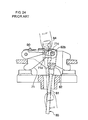
- a known brake cable connecting apparatus is such that a brake cable, mainly comprised of an inner cable and a clevis, is connected to a brake actuating mechanism comprised of a plate-like brake lever, a strut, a pivot pin and a washer, via a connecting pin.
- a brake actuating mechanism comprised of a plate-like brake lever, a strut, a pivot pin and a washer.
- a brake lever 71 has a cable connecting groove 71d in a free end 71c, and a spring member 90 urges the cable connecting groove 71d to cover thereof.
- a large and complex shaped spring member 90 is provided as an independent, essential component, thereby increasing production cost, such as material cost and processing cost and also increasing the assembly cost because of increasing the processing time due to the addition of the assembly process of the spring member 90 and the confirmation process of non-misassembly.
- the above-conventional type is disclosed in Japanese provisional patent publication number 2001-349359 (paragraphs 0005-0021, FIGS. 1-4).
- the brake cable connecting apparatus mainly comprises a regulating projection in the strut, which regulates the insertion depth of the connecting pin, to reduce the manual, complicated burden of inserting the connecting pin into the clevis of the brake cable.
- This invention is a brake cable connecting apparatus, which comprises a strut having a first shoe engagement portion which engages with one brake shoe and two facing surface walls which extend from a portion adjacent to the first shoe engagement portion in a direction away from the one brake shoe; a brake lever positioned in a space between the two facing surface walls, having a pivot portion which is pivotally supported on a free end of the two facing surface walls, a second shoe engagement portion which engages with the other brake shoe adjacent to the pivot portion, and a cable connecting groove formed on a free end away from the second engagement portion thereof; and a brake cable which is connected to the cable connecting groove via a connecting pin; the brake actuating mechanism moves the brake shoes away from each other as a result of relative rotation of the strut and brake lever about the pivot portion by operation of the brake cable, and the drum brake comprises a resilient member; if two facing plates of a clevis of the brake cable are placed into a space between the two facing surface walls of the strut and the brake lever and engagement holes of the clevis are
- This invention further is the above brake cable connecting apparatus wherein the regulating projection is formed at the side to which the connecting pin moves by its own weight.
- This invention still further is the above cable connecting apparatus, wherein a stopper restricting an insertion position of the two facing plates of the clevis is provided on the regulating projection of the strut.
- This invention still further is the above cable connecting apparatus, wherein the strut has a bridge to connect the two facing surface walls with each other and the cable disengagement restriction portion consists of the bridge and the free end of the brake lever.
- the resilient member is a shoe return spring.
- This invention yet further is the above brake cable connecting apparatus wherein the resilient member is a lever return spring extended between the strut and the brake lever.
- the regulating projection that regulates the insertion depth of the connecting pin, is provided to eliminate the operation of adjusting the insertion depth of the connecting pin to the clevis of the brake cable. Therefore, the connecting pin can be precisely engaged by easy operation of inserting the connecting pin until the end thereof abuts against the regulating projection, thereby eliminating the burden of adjusting the insertion depth of the connecting pin. Moreover, if the regulating projection is formed in the side to which the connecting pin moves by its own weight to prevent the connecting pin from falling off, it is unnecessary to retain the connecting pin by fingertips.
- the stopper which regulates the insertion position of the two facing plates of the clevis is added to the regulating projection of the strut, just by inserting the brake cable until the end of the clevis abuts against the strut, the engagement holes of the clevis move to a position where the connecting pin can be easily inserted; therefore, it is unnecessary to adjust the insertion position of the two facing plates of the clevis.
- the cable disengagement restriction portion and resilient member can be formed by existing parts, this invention reduces not only the material cost but the processing cost, thereby reducing the production cost and the assembly cost.
- the brake cable connecting apparatus has realized the purpose of reducing the burden of manual operation with a simple configuration whereby the connecting pin is inserted into the clevis of the brake cable.
- the first embodiments of the invention will be explained next in detail.
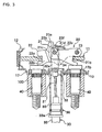
- FIG. 1 shows a plan view of a mechanical drum brake device with a brake cable connecting apparatus.
- the drum brake device is such that a pair of brake shoes 11, 12 are moveably supported by shoe hold mechanisms 13, 13 on a back plate 10 fixed to a stationary part (not shown in FIG. 1) of a vehicle body while one adjacent ends are supported by an anchor 17, and the other adjacent ends are connected to a connecting member 14. Both ends of the brake shoes 11, 12 abut against and are retained by an anchor 17 and a connecting member 14 by a pair of shoe return springs 15, 16 extended between both brake shoes 11, 12.
- the anchor 17 comprises the wall 17a and a base 17b, together making an L shape in cross section, and the base 17b is fixed to a stationary part 100 of the vehicle body while sandwiching the back plate 10 therebetween by screwing nuts (not shown in the figure) on insertion bolts 40.
- a brake cable 30 is connected to a free end 21c of a brake lever 21 and transfers the operation force of a parking lever (not shown in the figure) in a vehicle to the brake lever 21, where the brake cable 30 comprises an inner cable 31, a clevis 32, and an outer casting 33, wherein the clevis 32 is connected to the brake lever 21 via a connecting pin 34.
- the brake cable 30 comprises an inner cable 31, a clevis 32, and an outer casting 33, wherein the clevis 32 is connected to the brake lever 21 via a connecting pin 34.
- the brake lever 21 is made of a piece of plate and has a shoe engagement groove 21b, which engages with one brake shoe 11, and a pivot hole 21a where the pivot pin 23 is inserted at one end of the brake lever 21.
- the strut 22 is made of a piece of plate and is folded to make a U-shape with a pair of two facing surface walls 22a, 22b to retain the brake lever 21 therebetween and a bridge 22c at a longitudinal intermediate portion thereof. Moreover, left ends of the two facing surface walls 22a, 22b in FIGS. 3 and 4 are superposed on each other and are fixed, such as by welding.
- a wider space 22h which can retain the free end 21c of the brake lever 21 and the two facing plates 32a, 32a of the clevis 32, is formed between the two facing surface walls 22a, 22b at a longitudinal intermediate portion, and a narrower space 22j following the wider space 22h is formed.
- the superposed portion of the two facing surface walls 22a, 22b has a shoe engagement groove 22e, and pivot holes 22d, 22d are formed at the right ends of the strut 22 where the narrower space is formed.
- the above-described brake lever 21 is pivotally supported on the strut 22 via the pivot pin 23 which is inserted though the pivot holes 22d, 21a, 22d in order and where a washer 24 is clipped on an end thereof.
- a cable connecting groove 21d (which is connected to the clevis 32 via the connecting pin 34)
- a seating 21e (which temporarily places the connecting pin 34 that is engaged with the clevis 32) are formed on the upper side of the free end 21c of the brake lever 21.
- the bridge 22c is formed with a sloping surface as shown in FIG. 3, thereby guiding the ends of the two facing plates 32a, 32a of the clevis 32 smoothly along the sloping surface when the brake cable 30 is connected to the brake lever 21.
- a projection 22f which together with the free end 21c of the brake lever 21 comprises a cable disengagement restriction portion, is formed on the bridge 22c, and steps 22g, 22g are formed on both sides of the projection 22f, allowing the two facing plates 32a, 32a of the clevis 32, a component of the brake cable 30, to pass therethrough.
- the relationship between the bridge 22c of the strut 22 and the free end 21c of the brake lever 21 is to allow the connecting pin 34 to pass therebetween when the brake lever 21 rotates against the spring force of the shoe return springs 15, 16 as resilient members, and prevents the connecting pin 34 from passing therebetween when the brake cable 30 is tend to disengage from the cable connecting groove 21d.
- the steps 22g, 22g of the bridge 22c function to minimize the degree of leaning of the clevis 32 in the direction to the left side, as shown in FIG. 3, when the brake cable 30 is inserted to a position where the connecting pin 34 is engaged with the engagement holes 32b, 32b of the clevis 32. If the degree of leaning of the clevis 32 becomes large, a position where the connecting pin 34 is engaged greatly shifts to the left side shown in FIG. 3, and the seating 21e to temporarily place the connecting pin 34 also shifts to the left side, thereby requiring the longer free end 21c of the brake lever 21. Subsequently, the brake actuating mechanism 20 needs to become longer as a whole, thereby impacting on the cost and the layout.
- the above-described sloping surface and steps 22g, 22g both of the bridge 22c of the strut 22 are not essential components.
- the invention provides a regulating projection 22k on the strut 22 to regulate the insertion depth of the connecting pin 34 constantly when the connecting pin 34 is engaged with the clevis 32 in the operation of connecting the brake cable 30 to the brake lever 21.
- the regulating projection 22k is formed on one of the two facing surface walls 22a, 22b of the strut 22 at the cable releasing side and functions to prevent overinsertion of the connecting pin 34 when the connecting pin 34 is inserted from one side of the two facing plates 32a while the engagement holes 32b, 32b of the clevis 32 are placed on the upper side of the strut 22 shown in FIGS. 3-5.
- the embodiment shows the regulating projection 22k is formed on one of the two facing surface walls 22b in the central side of the brake when the brake actuating mechanism 20 is placed above a horizontal line passing through the center of the drum brake.
- the configuration of the regulating projection 22k is not limited to the embodiments shown in the figures because the regulating projection 22k has only to prevent movement of the above-described connecting pin 34.
- the brake cable 30 disclosed in FIGS. 3-5 is comprised of the inner cable 31 and the outer casing 33, and one end at the drum brake side is structured as follows.
- One end of the brake cable 30 is inserted into a guide pipe 35 fixed to the base 17b of the anchor 17 at one end of the guide pipe 35, and a casing cap 33a of the outer casing 33 fits in the other end of the guide pipe 35 and is clipped by a ring 36.
- the clevis 32 fixed to the end of the inner cable 31 has a pair of the two facing plates 32a, 32a spaced to retain the brake lever 21 therebetween, and each of the two facing plates 32a, 32a has the engagement holes 32b, 32b formed in the same axial line to insert the connecting pin 34 therethrough.
- the groove is sufficiently deep so that the engagement holes 32b, 32b of the clevis 32 can be exposed upward from the free end 21c of the brake lever 21 in FIGS. 3-5.
- the connecting pin 34 penetrates and is extended between the end of the two facing plates 32a, 32a of the clevis 32 and directly slides into the inner circumference surface of the cable connecting groove 21d formed on the free end 21c of the brake lever 21.
- the entire length of the connecting pin 34 is designed to be shorter than the width between the two facing surface walls 22a, 22b of the strut 22, so that the connecting pin 34 is able to be inserted into the engagement holes 32b, 32b of the clevis 32,thereby laterally bridging between the two facing plates 32a, 32a.
- the length of the connecting pin 34 is designed to have an engagement margin between the engagement holes 32b, 32b of the clevis 32 even if one side of the connecting pin 34 abuts against the inner surface of either one of the two facing surface walls 22a, 22b of the strut 22.
- the clevis 32 is inserted into the strut 22 through the inside of the guide pipe 35 by forwarding the inner cable 31 which is held by the fingertips. While the free end 21c of the brake lever 21 is retained in the groove formed between the two facing plates 32a, 32a of the clevis 32, a pair of the two facing plates 32a, 32a moves into each space formed between the two facing surface walls 22a, 22b of the strut 22 and the free end 21c of the brake lever 21, and the end of the clevis 32 reaches the guiding surface (the above-mentioned sloping surface) of the bridge 22c of the strut 22 (FIG. 6).
- the end of the clevis 32 slides along the guiding surface of the bridge 22c of the strut 22, and the clevis 32, while tilting (so-called head swing) gradually keeps moving into the top of the free end 21c of the brake lever 21.
- the end of the clevis 32 reaches the steps 22g, 22g of the bridge 22c (see FIG. 2 and FIG. 4)
- the end of the clevis 32 slides and moves into the steps 22g, 22g, and the side of the two facing plates 32a, 32a keeps moving into the lower part of the steps 22g, 22g by the resilience of the inner cable 31.
- the clevis 32 reaches a position where the engagement holes 32b, 32b of the two facing plates 32a, 32a are exposed entirely from the opening of the strut 22.
- the connecting pin 34 is inserted into the engagement holes 32b, 32b of the clevis 32 from the side where the regulating projection 22k is not formed, and closes the opening of the pair of the two facing plates 32a, 32a.
- the engagement holes 32b, 32b of the clevis 32 In the engagement holes 32b, 32b of the clevis 32, the engagement holes 32b of the two facing plates 32a, placed in the central side of the brake, are closed by the restricting projection 22k, even if the connecting pin 34 is strongly inserted. Therefore, the connecting pin 34 can be inserted into the clevis 32 at a constant depth (see FIG.7 and FIG. 8) due to restriction of the movement by the restricting projection 22k.
- the connecting pin 34 can be engaged with the two facing plates 32a, 32a of the clevis 32 by easily inserting the connecting pin 34 until the end of the connecting pin 34 abuts against the regulating projection 22k of the strut 22, the burden of adjusting the insertion depth of the connecting pin 34 by fingertips can be eliminated, thereby improving the connecting operation of the brake cable 30 to the brake lever 21.
- the phantom line (two-dot chain line) in FIG. 9 shows the seating 21e of the brake lever 21, the clevis 32 and the connecting pin 34 in the condition after the inner cable 31 is pulled and before the brake lever 21 rotates. Under this condition, because the gap 25 formed between the projection 22f of the bridge 22c of the strut 22 and the free end 21c of the brake lever 21 is smaller than the diameter of the connecting pin 34, the connecting pin 34 abuts against the projection 22f and the seating 21e.
- the brake lever 21 rotates in the cable releasing direction by the return force of the shoe return springs 15, 16, and returns to the initial condition, and the cable disengagement restriction portion, consisting of the bridge 22c of the strut 22 and the free end 21c of the brake lever 21, also returns to its initial condition.
- the end of the clevis 32 abuts against the back side (guiding surface) of the bridge 22c of the strut 22, thereby limiting the free movement of the clevis 32 relative to the brake lever 21 in the cable releasing direction.
- This configuration prevents the clevis 32 from moving to a position where the connecting pin 34 falls out from the engagement holes 32b, 32b, thereby preventing inadvertent disengagement of the brake cable 30 from the brake lever 21 while transporting the drum brake.
- the return force of the brake lever 21 can be obtained from the existing shoe return springs 15, 16 as resilient members, which ensures prevention of disengagement of the clevis 32 from the free end 21c of the brake lever 21 without any additional component.
- the brake cable connecting apparatus of the second embodiment of the invention will be explained with reference to FIGS. 10-16.
- the embodiment shows a stopper 22m which functions to prevent overinsertion of the clevis 32 that is added to the regulating projection 22k of the strut 22 in order to arrange the engagement holes 32b, 32b of the clevis 32 to a position where the connecting pin 34 is easily inserted.
- the embodiment shows an example of the regulating projection 22k, to prevent overinsertion of the connecting pin 34, formed on one of the two facing surface walls 22a outside of the brake.
- the strut 22 of the embodiment has the bridge 22c in a different part from that of the above-described first embodiment.
- the stopper 22m is formed by bending the end portion of the regulating projection 22k, which is formed on one facing surface wall 22a, towards the other facing surface wall 22b so as to arrange the engagement holes 32b, 32b of the clevis 32 to a position where the connecting pin 34 is easily inserted.
- the projection of the stopper 22m is required to be long enough to be able to abut against one or both of the two facing plates 32a, 32a comprising the clevis 32.
- the embodiment shows an example where the entire shape of the stopper 22m is formed into an arc shape in accordance with the shape of the end of the clevis 32. However, the entire shape is not limited to the arc shape so long as the above-described positioning function is achieved.
- a tongue 22n is formed by bending the other facing surface wall 22b, which is on the opposite side of the regulating projection 22k.
- the projection 22f is formed by bending the tongue 22n towards the cable operating direction, which is the opposite of the first embodiment.
- the projection 22f is placed above the cable connecting groove 21d of the brake lever 21, and the gap 25 between the projection 22f and the free end 21c of the brake lever 21 becomes smaller than the diameter of the connecting pin 34.
- the guiding portion 21f protrudes from the side of the brake lever 21, which can smoothly guide the end of the clevis 32 along the guiding portion 21f when the brake cable 30 is connected to the brake lever 21.
- the drum brake of the embodiment has the brake actuating mechanism 20 below a horizontal line passing through the center of the brake as shown in FIG. 10, and the regulating projection 22k is placed outside of the brake to prevent the connecting pin 34 from falling out by its own weight in the initial stage of the brake cable connecting operation.
- the shoe hold mechanisms 13, 13 where a pair of brake shoes 11, 12 are supported on the back plate 10 employ a coil spring.
- the embodiment of the shoe hold mechanisms is not limited to the first or second embodiments.
- the clevis 32 is inserted into the strut 22 through the inside of the guide pipe 35 by forwarding the inner cable 31 which is held by finger tips. While the free end 21c of the brake lever 21 is retained in the groove formed between the two facing plates 32a, 32a of the clevis 32, a pair of two facing plates 32a, 32a moves into each space formed between the two facing surface walls 22a, 22b of the strut 22 and the free end 21c of the brake lever 21, and in the inserting process of the end of the clevis 32, the end of the clevis 32 is guided towards the stopper 22m formed on the strut 22 while being guided along the guiding portion 21f provided on the side of the brake lever 21.
- the engagement holes 32b, 32b of the clevis 32 are positionedas shown with one of the engagement holes 32b in FIG. 15, the engagement holes 32b, 32b reach a position where the engagement holes 32b, 32b are exposed entirely from the opening of the strut 22.
- the embodiment shows that the engagement holes 32b, 32b of the clevis 32 can be arranged at a position where the connecting pin 34 is easily inserted just by inserting the inner cable 31 until the end of the clevis 32 abuts against the stopper 22m of the strut 22.
- the connecting pin 34 is inserted from the side where the regulating projection 22k is not provided into the engagement holes 32b, 32b of the clevis 32 until the end of the connecting pin 34 abuts against the regulating projection 22k of the strut 22.
- the regulating projection 22k functions to prevent overinsertion of the connecting pin 34.
- FIG. 16 shows the seating 21e of the brake lever 21 and the clevis 32 in the condition after the inner cable 31 is pulled and before the brake lever 21 rotates.
- the connecting pin 34 abuts against the projection 22f and the seating 21e.
- the brake lever 21 rotates further, making the gap 25 larger than the diameter of the connecting pin 34, and the connecting pin 34 is retained in and engaged with the cable connecting groove 21d after passing the gap 25.
- the brake lever 21 rotates in the cable releasing direction by the return force of the shoe return springs 15, 16, and returns to the initial condition, and the cable disengagement restriction portion that consists of the projection 22f of the strut 22 and the free end 21c of the brake lever 21, also returns to the initial condition. This can prevent inadvertent disengagement of the brake cable 30 from the brake lever 21.
- the resilient member which brings return force to the brake lever 21 is the existing shoe return spring.
- the resilient member can be an independent lever return spring 50 as shown in this third embodiment.
- the lever return spring 50 is a torsion coil spring comprising a pair of arms 51, 52 that are formed into a V shape and where the pair of arms 51, 52 converge they are bent into a loop shape to form a coil portion 53, and the free ends of each arm 51, 52 are bent at a right angle, forming hooking portions 54, 55, each having a different length.
- the coil portion 53 is placed on one side of the strut 22; the pair of arms 51, 52 extending from the coil portion 53 are placed towards the pivot portion of the strut 22 and the brake lever 21; and a long hook 54 and a short hook 53, which are bent at the ends of the arms 51, 52, are seated on a pair of the two facing surface walls 22a, 22b of the strut 22 and the brake lever 21 respectively, which brings return force to the brake lever 21 in the cable releasing direction by the return force of the lever return spring 50.
- this embodiment shows that the regulating projection 22k functions to prevent the above-explained overinsertion of the connecting pin 34. Also, the gap 25 formed between the projection 22f of the strut 22 and the free end 21c of the brake lever 21 is kept smaller than the diameter of the connecting pin 34, which can prevent inadvertent disengagement of the clevis 32 from the free end 21c of the brake lever 21.
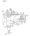
- the brake cable connecting apparatus of the fourth embodiment of the invention will be explained with reference to FIGS. 20-23.
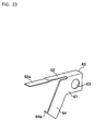
- the embodiment employs an independent component, a stopper spring 60 shown in FIG. 23, as a means to prevent disengagement of the clevis 32 connected to the free end 21c of the brake lever 21 from the brake lever 21.
- the stopper spring 60 comprises a proximal end 61 which is bent into an L-shaped cross-section, an elongated long arm 62 extending from the proximal end 61, and an anti-rotation portion 64 (which will be described later) and the proximal end 61 provided between either one of the two facing surface walls 22a, 22b of the strut 22 and the brake lever 21 has an engagement hole 63 to be pivotally attached via the pivot pin 23.
- the long arm 62 provided between the tongue 22n of the strut 22 and the brake lever 21 has an end 62a, which partly protrudes above the brake connecting groove 21d of the brake lever 21 as shown in FIGS. 21-22.
- the object members which prevent the connecting pin 34 from falling out are different from those of the aforementioned first to third embodiments, comprising the end 62a of the stopper spring 60 which partly protrudes above the cable connecting groove 21d of the brake lever 21 and the free end 21c of the brake lever 21.
- the gap 25 between the end 62a of the stopper spring 60 and the free end 21c of the brake lever 21 is formed smaller than the diameter of the connecting pin 34.
- a characteristic of the aforementioned stopper spring 60 is that together with the tongue 22n of the strut 22, the spring constant of the long arm 62 increases and decreases by changing the starting point where the long arm 62 is deformed in accordance with the direction of rotating of the stopper spring 60, and the spring constant of the long arm 62 increases overwhelmingly to the spring constant of the long arm 62 in connecting the clevis 32 with the connecting pin 34 to the brake lever 21 when the clevis 32 having the connecting pin 34 is disengaged from the brake lever 21 after engaged with the cable connecting groove 21d of the brake lever 21.
- An anti-rotation portion 64 is placed from the proximal end 61 towards the lower side of the brake lever 21 as shown in FIGS. 21-22.
- An engagement portion 64a which is engaged with the side of the brake lever 21, is formed by bending the end of the anti-rotation portion 64 in a through-thickness direction of the brake lever 21, and therefore a large rotation of the stopper spring 60 relative to the brake lever 21 is restricted.
- the stopper spring 60 placed on the brake actuating mechanism 20 will be explained below.
- the clevis 32 is inserted from the outside of the brake through the guide pipe 35 shown in FIG. 21 and then passed through the inside of the strut 22, and finally the connecting pin 34 is inserted into the clevis 34, utilizing the regulating projection 22k formed on the strut 22.
- the gap 25 formed between the end 62a of the stopper spring 60 and the free end 21c of the brake lever 21 is smaller than the diameter of the connecting pin 34, which does not allow the connecting pin 34 to pass through the gap 25.
- the connecting pin 34 abuts against the end 62a of the stopper spring 60 and the free end 21c, then the long arm 62 is deformed in the cable operating direction at the tip part from the contact part P1 of the midpoint of the long arm 62 and the brake lever 21, thereby widening the gap 25.
- the connecting pin 34 When the gap 25 becomes larger than the diameter of the connecting pin 34, the connecting pin 34 is allowed to pass through the gap 25 and is retained in the cable connecting groove 21d, which completes the engagement. After the connecting pin 34 passes through the gap 25, the long arm 62 of the stopper spring 60 returns to the initial position with its own return force, and the end 62a is disposed projectedly in the cable connecting groove 21d of the brake lever 21.
- Such a configuration can prevent disengagement of the clevis 32 from the brake lever 21 during the transportation of the drum brake device.
Landscapes
- Engineering & Computer Science (AREA)
- General Engineering & Computer Science (AREA)
- Mechanical Engineering (AREA)
- Braking Arrangements (AREA)
Applications Claiming Priority (1)
| Application Number | Priority Date | Filing Date | Title |
|---|---|---|---|
| JP2004294059A JP2006105301A (ja) | 2004-10-06 | 2004-10-06 | ブレーキケーブル接続装置 |
Publications (3)
| Publication Number | Publication Date |
|---|---|
| EP1645770A2 EP1645770A2 (en) | 2006-04-12 |
| EP1645770A3 EP1645770A3 (en) | 2006-05-17 |
| EP1645770B1 true EP1645770B1 (en) | 2007-12-12 |
Family
ID=35483498
Family Applications (1)
| Application Number | Title | Priority Date | Filing Date |
|---|---|---|---|
| EP05292079A Ceased EP1645770B1 (en) | 2004-10-06 | 2005-10-06 | Brake cable connecting apparatus for a drum brake |
Country Status (3)
| Country | Link |
|---|---|
| US (1) | US7434668B2 (2) |
| EP (1) | EP1645770B1 (2) |
| JP (1) | JP2006105301A (2) |
Families Citing this family (6)
| Publication number | Priority date | Publication date | Assignee | Title |
|---|---|---|---|---|
| US8875847B2 (en) * | 2005-08-09 | 2014-11-04 | Nisshinbo Holdings, Inc. | Mechanical brake actuator |
| US7261190B1 (en) * | 2005-08-23 | 2007-08-28 | Robert Bosch Gmbh | Reaction lever for a parking brake |
| JP4721222B2 (ja) * | 2006-01-11 | 2011-07-13 | 日清紡ホールディングス株式会社 | 機械式ブレーキ作動装置 |
| US8267227B2 (en) * | 2008-07-22 | 2012-09-18 | Akebono Brake Corporation | Lever assembly featuring blind cable assembly |
| US20110100772A1 (en) * | 2009-11-05 | 2011-05-05 | Akebono Corporation (North America) | Cable end retention clip assembly and method |
| CN109238343B (zh) * | 2018-10-09 | 2024-04-09 | 厦门大学 | 一种海洋探测装置的探测仪的回收方法 |
Family Cites Families (8)
| Publication number | Priority date | Publication date | Assignee | Title |
|---|---|---|---|---|
| US5720367A (en) * | 1995-08-23 | 1998-02-24 | Kelsey-Hayes Company | Parking and emergency brake operating mechanism for dual mode drum brake assemlby |
| JP4468536B2 (ja) * | 1999-04-01 | 2010-05-26 | 日清紡ホールディングス株式会社 | 操作ケーブルの接続装置 |
| JP4371286B2 (ja) * | 2000-04-12 | 2009-11-25 | 日清紡ホールディングス株式会社 | 操作ケーブルの接続装置 |
| JP2001349359A (ja) * | 2000-06-08 | 2001-12-21 | Akebono Brake Ind Co Ltd | 機械式ドラムブレーキのレバーとケーブルの接続構造 |
| JP2002364688A (ja) * | 2001-06-08 | 2002-12-18 | Nisshinbo Ind Inc | ブレーキケーブル接続装置 |
| JP3867005B2 (ja) * | 2002-04-08 | 2007-01-10 | 日本ブレーキ工業株式会社 | ドラムブレーキ装置 |
| JP4096105B2 (ja) * | 2002-09-17 | 2008-06-04 | 日清紡績株式会社 | ブレーキケーブルの接続装置 |
| JP4005894B2 (ja) * | 2002-09-27 | 2007-11-14 | 日清紡績株式会社 | ブレーキケーブルの接続装置 |
-
2004
- 2004-10-06 JP JP2004294059A patent/JP2006105301A/ja active Pending
-
2005
- 2005-10-06 US US11/245,328 patent/US7434668B2/en not_active Expired - Fee Related
- 2005-10-06 EP EP05292079A patent/EP1645770B1/en not_active Ceased
Also Published As
| Publication number | Publication date |
|---|---|
| EP1645770A3 (en) | 2006-05-17 |
| JP2006105301A (ja) | 2006-04-20 |
| US20060070825A1 (en) | 2006-04-06 |
| US7434668B2 (en) | 2008-10-14 |
| EP1645770A2 (en) | 2006-04-12 |
Similar Documents
| Publication | Publication Date | Title |
|---|---|---|
| EP1645770B1 (en) | Brake cable connecting apparatus for a drum brake | |
| CN100392211C (zh) | 用于内燃机的气门控制系统中的摇臂组件 | |
| US20060091712A1 (en) | Seat reclining apparatus | |
| JP2002065387A (ja) | 車両用シートリクライニング装置 | |
| US7231866B2 (en) | Opening and closing switch structure for valve pin control of gas cylinder | |
| US20050067871A1 (en) | Drive having a sliding element for a vehicle seat adjuster | |
| US20020007990A1 (en) | Brake cable connecting apparatus for drum brake | |
| EP2080924B1 (en) | Shoe-hold apparatus for drum brake device | |
| US7070025B2 (en) | Drum brake apparatus | |
| JP4336604B2 (ja) | フューエルリッド装置 | |
| EP1808614B1 (en) | Mechanical brake actuator | |
| EP1041301A2 (en) | Connecting device for control cable | |
| US6003945A (en) | Seat reclining mechanism for vehicles | |
| US7690855B2 (en) | Binding tool for documents or the like | |
| JP2002364688A (ja) | ブレーキケーブル接続装置 | |
| EP1174627B9 (en) | Brake cable connecting apparatus for drum brake | |
| US6502670B1 (en) | Mechanical type drum brake device | |
| US6260923B1 (en) | Seat reclining mechanism for vehicles | |
| EP1433652A1 (en) | Recliner adjuster for a seat | |
| US20020170998A1 (en) | Tape cartidge | |
| JP2002106620A (ja) | ドラムブレーキのシュー間隙過調整防止装置 | |
| EP2202424B1 (en) | Mechanical type brake actuator for drum brake | |
| JPH1068308A (ja) | バルブ制御システム | |
| EP1580460A2 (en) | A selector apparatus of an automatic transmission of vehicle | |
| EP1643153A2 (en) | Brake cable connecting apparatus for a drum brake device |
Legal Events
| Date | Code | Title | Description |
|---|---|---|---|
| PUAI | Public reference made under article 153(3) epc to a published international application that has entered the european phase |
Free format text: ORIGINAL CODE: 0009012 |
|
| PUAL | Search report despatched |
Free format text: ORIGINAL CODE: 0009013 |
|
| AK | Designated contracting states |
Kind code of ref document: A2 Designated state(s): AT BE BG CH CY CZ DE DK EE ES FI FR GB GR HU IE IS IT LI LT LU LV MC NL PL PT RO SE SI SK TR |
|
| AX | Request for extension of the european patent |
Extension state: AL BA HR MK YU |
|
| AK | Designated contracting states |
Kind code of ref document: A3 Designated state(s): AT BE BG CH CY CZ DE DK EE ES FI FR GB GR HU IE IS IT LI LT LU LV MC NL PL PT RO SE SI SK TR |
|
| AX | Request for extension of the european patent |
Extension state: AL BA HR MK YU |
|
| 17P | Request for examination filed |
Effective date: 20061006 |
|
| AKX | Designation fees paid |
Designated state(s): FR |
|
| REG | Reference to a national code |
Ref country code: DE Ref legal event code: 8566 |
|
| GRAP | Despatch of communication of intention to grant a patent |
Free format text: ORIGINAL CODE: EPIDOSNIGR1 |
|
| GRAS | Grant fee paid |
Free format text: ORIGINAL CODE: EPIDOSNIGR3 |
|
| GRAA | (expected) grant |
Free format text: ORIGINAL CODE: 0009210 |
|
| AK | Designated contracting states |
Kind code of ref document: B1 Designated state(s): FR |
|
| ET | Fr: translation filed | ||
| PLBE | No opposition filed within time limit |
Free format text: ORIGINAL CODE: 0009261 |
|
| STAA | Information on the status of an ep patent application or granted ep patent |
Free format text: STATUS: NO OPPOSITION FILED WITHIN TIME LIMIT |
|
| 26N | No opposition filed |
Effective date: 20080915 |
|
| REG | Reference to a national code |
Ref country code: FR Ref legal event code: PLFP Year of fee payment: 12 |
|
| REG | Reference to a national code |
Ref country code: FR Ref legal event code: PLFP Year of fee payment: 13 |
|
| REG | Reference to a national code |
Ref country code: FR Ref legal event code: CD Owner name: NISSHINBO BRAKE INC., JP Effective date: 20180613 Ref country code: FR Ref legal event code: TP Owner name: NISSHINBO BRAKE INC., JP Effective date: 20180613 |
|
| REG | Reference to a national code |
Ref country code: FR Ref legal event code: PLFP Year of fee payment: 14 |
|
| PGFP | Annual fee paid to national office [announced via postgrant information from national office to epo] |
Ref country code: FR Payment date: 20210913 Year of fee payment: 17 |
|
| PG25 | Lapsed in a contracting state [announced via postgrant information from national office to epo] |
Ref country code: FR Free format text: LAPSE BECAUSE OF NON-PAYMENT OF DUE FEES Effective date: 20221031 |