EP1647201A1 - Brush ring assembly - Google Patents
Brush ring assembly Download PDFInfo
- Publication number
- EP1647201A1 EP1647201A1 EP04077736A EP04077736A EP1647201A1 EP 1647201 A1 EP1647201 A1 EP 1647201A1 EP 04077736 A EP04077736 A EP 04077736A EP 04077736 A EP04077736 A EP 04077736A EP 1647201 A1 EP1647201 A1 EP 1647201A1
- Authority
- EP
- European Patent Office
- Prior art keywords
- brush
- mentioned
- ring
- core part
- shaped
- Prior art date
- Legal status (The legal status is an assumption and is not a legal conclusion. Google has not performed a legal analysis and makes no representation as to the accuracy of the status listed.)
- Granted
Links
- 238000010408 sweeping Methods 0.000 claims abstract description 21
- 238000010276 construction Methods 0.000 claims description 7
- 230000001174 ascending effect Effects 0.000 claims description 6
- -1 for example Polymers 0.000 claims description 6
- 239000004743 Polypropylene Substances 0.000 claims description 3
- 239000000463 material Substances 0.000 claims description 3
- 239000004033 plastic Substances 0.000 claims description 3
- 229920001155 polypropylene Polymers 0.000 claims description 3
- 229910000831 Steel Inorganic materials 0.000 claims 1
- 239000002184 metal Substances 0.000 claims 1
- 239000010959 steel Substances 0.000 claims 1
- 230000008901 benefit Effects 0.000 description 4
- 238000005352 clarification Methods 0.000 description 1
- 230000004048 modification Effects 0.000 description 1
- 238000012986 modification Methods 0.000 description 1
Images

Classifications
-
- A—HUMAN NECESSITIES
- A46—BRUSHWARE
- A46B—BRUSHES
- A46B13/00—Brushes with driven brush bodies or carriers
- A46B13/001—Cylindrical or annular brush bodies
- A46B13/003—Cylindrical or annular brush bodies made up of a series of annular brush rings; Annular brush rings therefor
-
- A—HUMAN NECESSITIES
- A46—BRUSHWARE
- A46B—BRUSHES
- A46B2200/00—Brushes characterized by their functions, uses or applications
- A46B2200/30—Brushes for cleaning or polishing
- A46B2200/3066—Brush specifically designed for use with street cleaning machinery
Definitions
- the present invention relates to a device constructed as an assembly of ring-shaped brushes, axially placed against each other on a shaft-shaped pick-up instrument, also called brush rings, in which these consist of a ring shaped core part with around that the radial protruding brush part, in which the mentioned core part of the separate brush rings are mounted axially rotation fixed in order to form a mostly horizontal shaft-shaped pick-up instrument, so that by driving the sweeping machine a rotating cylindrical sweeping brush assembly is created.
- the above mentioned set of brush rings placed in relation to each other have only one transport position and one users position, through which especially a further or more precise adjustment of the number of brush rings placed against each other on the shaft-shaped pick-up instrument and thus the adjustment of the sweeping intensity and/or the number of sweeping threads per surface unit of the sweeping cylinders of the sweeping machine is not possible.
- the latter is especially of importance if surfaces in dimension, thus surfaces more or less or adjusted, need to be sweeped.
- a device constructed as an assembly of ring-shaped brushes axially placed against each other according to the invention is further developed and/or modified in a very inventive way, characterized in that, the mentioned ring-shaped core part of the separate brush rings in a multiple of successively at least two steps descending and every time in only one step ascending is deformed almost vertical onto the flat ring-shaped core part, in which the mentioned deformation of descending and ascending steps is applied in a multiple n along the circumference of the ring-shaped core part.
- the advantage is, that as regards intensity of the brush surface, a very flexible adjustable brush ring assembly is created, which assembly can be used for very different, more or less intensive surfaces to be sweeped.
- the economy is also in the benefit, because by adjustment, the surface to be sweeped can mechanically be less affected and for lighter sweeping work, one can use less brush rings for the cylindrical brush ring assembly.
- n is at least 3 and with larger diameters preferably 5 and more, in which the mentioned ring-shaped core part is applied rotation fixed by means of an axial catch pin and groove construction along the radial inner circumference of the ring-shaped core part and along the radial outer circumference of the mentioned shaft-shaped pick-up instrument.
- the device according to the invention is further developed in such a way, that the mentioned ring-shaped brushes, placed on the shaft-shaped pick-up instrument of the sweeping machine can be locked at the ends with a fast mountable flange or disc construction.
- the advantage is a very handy and simple catch pin- and groove construction to mount and lock the separate brush rings in the required position onto the shaft-shaped pick-up instrument.
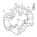
- Figure 1 shows a front view in oblique projection of the most dense stacking of the core part 2 of the separate brush ring 1 (see figure 4), in which the radially protruding fibres 7 (see figure 4) are left out.
- the core part 2 is deformed each time in at least two steps or positions 5-4 and 4-3 descending and each time in one step 3-5 ascending almost vertical to the flat surface to the original ring-shaped core part 2.
- the rotation fixation of the core parts 2 and 2 1 is in this embodiment constructed by the centric protruding instrument or cams or catch pins 6, which stick into the not shown axial grooves of the shaft-shaped pick-up instrument.
- the mentioned axial grooves are applied over a suitable angle dependant on the value n on or over the shaft-shaped pick-up instrument in order to create the positions of the core parts 2 and 2 1 to respectively the most dense, medium and most open brush or by more steps into even more positions.
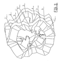
- Figure 2 shows the most open stacked brush rings in oblique projection, as also shown in figure 3C. At the most open brush a minimum quantity of brush rings 1 come onto the not shown shaft-shaped pick-up instrument of the sweeping machine.
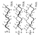
- Figures 3A, 3B and 3C show in side view along the circumference of the brush ring 1 (see also figure 4), the most dense stacking (figure 3A), the medium stacking (figure 3B) and the most open stacking of the core parts 2 and 2 1 of the brush rings 1 at an n of 3, in which n shows the number of deformations of the descending and ascending steps along the circumference vertical onto the brush surface of the core part 2, 2 1 .
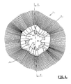
- Figure 4 shows a front view of the complete brush ring 1, in which the core part 2, 2 1 is shown in steps with the same indication numbers of steps 5-4, 4-3 and 3-5 or 5 1 -4 1 , 4 1 -3 1 and 3 1 -5 1 .
- the core part 2, 2 1 with the radial brush part 7 is mostly made as a whole of plastic, such as, for example, polypropylene.
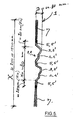
- Figure 5 shows over the line V-V of figure 4 a cross-section of the brush ring 1 according to a preferred embodiment of the invention. The different steps and parts are each time indicated with the same numbers.
- Figure 6 shows a front view of the core part 2 of the brush ring 1 only, in which the different steps of 5-4, 4-3 and 3-5 are shown along the circumference of the 20 mm broad edge. Also the catch pins 6, in this case 4 pieces, are shown.
- the successive core parts can be turned over suitable angles to lie against the different surfaces 5, 4 and 3, through which the catch pins 6 can be turned over the mentioned angles over the grooves in the shaft-shaped pick-up instrument, through which a suitable brush density s created.
- Figure 7 shows a side view over the line VII of figure 6 for clarification, in which the brush threads are left out.
Landscapes
- Brushes (AREA)
- Cleaning In General (AREA)
- Motor Or Generator Current Collectors (AREA)
- Turbine Rotor Nozzle Sealing (AREA)
Abstract
Description
- The present invention relates to a device constructed as an assembly of ring-shaped brushes, axially placed against each other on a shaft-shaped pick-up instrument, also called brush rings, in which these consist of a ring shaped core part with around that the radial protruding brush part, in which the mentioned core part of the separate brush rings are mounted axially rotation fixed in order to form a mostly horizontal shaft-shaped pick-up instrument, so that by driving the sweeping machine a rotating cylindrical sweeping brush assembly is created.
- Similar brush rings, which are placed against each other on a shaft-shaped pick-up instrument of a sweeping machine, are known in the European
Patent document EP 1 009 254 B1, titled: "BRUSH RING", from Sajakorpi OY, 33101 Tampere, Finland, submitted 21-08-1997, with inventors SAJAKORPI, Kimmo and KUIVIIKO, Reijo. Here, it concerns a deformed core part descending with a single step from its flat surface and ascends with a single step with a rotational pick-up instrument in order to be able to transport a compact package to the user and to assemble for practical use by mutual rotation the cylindrical brush rings over a wavelength, which consists of as little brush rings as possible and still creates a relatively equal brush thread division along the formed cylindrical surface of the finished brush for the sweeping machine. Besides the core part and the brush part in its whole are made of a plastic material, being polypropylene. This means that after severe wear of the radial protruding brush threads the complete brush ring assembly must be replaced. - As already mentioned, the above mentioned set of brush rings placed in relation to each other have only one transport position and one users position, through which especially a further or more precise adjustment of the number of brush rings placed against each other on the shaft-shaped pick-up instrument and thus the adjustment of the sweeping intensity and/or the number of sweeping threads per surface unit of the sweeping cylinders of the sweeping machine is not possible. The latter is especially of importance if surfaces in dimension, thus surfaces more or less or adjusted, need to be sweeped. Also, one can not work economically because the mutual distance of the brush rings only allow a single position, through which always the maximum number of brush rings must be mounted on the shaft-shaped pick-up instrument of the sweeping machine.
- In short, for daily practice the known brush rings have a number of disadvantages.
- It is the aim of the present invention to provide such an improved brush ring assembly constructed of separate brush rings, which are deformed from their ring surface and in which the aforementioned disadvantages are solved and which separate brush rings can be put onto the market in a economical responsible way.
- For this, a device constructed as an assembly of ring-shaped brushes axially placed against each other according to the invention is further developed and/or modified in a very inventive way, characterized in that, the mentioned ring-shaped core part of the separate brush rings in a multiple of successively at least two steps descending and every time in only one step ascending is deformed almost vertical onto the flat ring-shaped core part, in which the mentioned deformation of descending and ascending steps is applied in a multiple n along the circumference of the ring-shaped core part.
- The advantage is, that as regards intensity of the brush surface, a very flexible adjustable brush ring assembly is created, which assembly can be used for very different, more or less intensive surfaces to be sweeped. The economy is also in the benefit, because by adjustment, the surface to be sweeped can mechanically be less affected and for lighter sweeping work, one can use less brush rings for the cylindrical brush ring assembly.
- Further, the device according to the invention is further developed in such a way, that n is at least 3 and with larger diameters preferably 5 and more, in which the mentioned ring-shaped core part is applied rotation fixed by means of an axial catch pin and groove construction along the radial inner circumference of the ring-shaped core part and along the radial outer circumference of the mentioned shaft-shaped pick-up instrument.
- The advantages are, that an optimal adjustment can be reached and with that, the rotation fixation of the brush rings is also reasonably simple to do.
- Furthermore, the device according to the invention is further developed in such a way, that the mentioned ring-shaped brushes, placed on the shaft-shaped pick-up instrument of the sweeping machine can be locked at the ends with a fast mountable flange or disc construction.
- The advantage is a very handy and simple catch pin- and groove construction to mount and lock the separate brush rings in the required position onto the shaft-shaped pick-up instrument.
- The preferred construction of the invention will be described by way of example, and with reference to the accompanying drawing.
- In which:
- Fig. 1
- shows a view in oblique projection of the core part of a separate brush ring, in which the radial protruding fibres are left out and the core part is constructed according to a preferred embodiment of the invention, for a compact transport and stock of it and to be able to form several densities of the brush ring assembly;
- Fig. 2
- shows a view in oblique projection of the most open stacked or placed beside each other brush rings, shown without the fibres forming the brush parts, according to the invention;
- Fig. 3A-3C
- shows a partly side view along the circumference of the stacking or placing possibilities of the brush rings in the most dense, medium and most open stack, according to the invention;
- Fig. 4
- shows a front view of the complete brush ring according to a preferred embodiment of the invention;
- Fig. 5
- shows a cross-section over the line V-V of figure 4;
- Fig. 6
- shows a front view of the core part of the brush ring in scale; and
- Fig. 7
- shows a front view over the line VII of figure 6.
- Figure 1 shows a front view in oblique projection of the most dense stacking of the
core part 2 of the separate brush ring 1 (see figure 4), in which the radially protruding fibres 7 (see figure 4) are left out. Thecore part 2 is deformed each time in at least two steps or positions 5-4 and 4-3 descending and each time in one step 3-5 ascending almost vertical to the flat surface to the original ring-shaped core part 2. The rotation fixation of thecore parts catch pins 6, which stick into the not shown axial grooves of the shaft-shaped pick-up instrument. The mentioned axial grooves are applied over a suitable angle dependant on the value n on or over the shaft-shaped pick-up instrument in order to create the positions of thecore parts - Figure 2 shows the most open stacked brush rings in oblique projection, as also shown in figure 3C. At the most open brush a minimum quantity of
brush rings 1 come onto the not shown shaft-shaped pick-up instrument of the sweeping machine. - Figures 3A, 3B and 3C show in side view along the circumference of the brush ring 1 (see also figure 4), the most dense stacking (figure 3A), the medium stacking (figure 3B) and the most open stacking of the
core parts brush rings 1 at an n of 3, in which n shows the number of deformations of the descending and ascending steps along the circumference vertical onto the brush surface of thecore part - Figure 4 shows a front view of the
complete brush ring 1, in which thecore part core part radial brush part 7 is mostly made as a whole of plastic, such as, for example, polypropylene. - Figure 5 shows over the line V-V of figure 4 a cross-section of the
brush ring 1 according to a preferred embodiment of the invention. The different steps and parts are each time indicated with the same numbers. - Figure 6 shows a front view of the
core part 2 of thebrush ring 1 only, in which the different steps of 5-4, 4-3 and 3-5 are shown along the circumference of the 20 mm broad edge. Also thecatch pins 6, in thiscase 4 pieces, are shown. The successive core parts can be turned over suitable angles to lie against thedifferent surfaces catch pins 6 can be turned over the mentioned angles over the grooves in the shaft-shaped pick-up instrument, through which a suitable brush density s created. - Figure 7 shows a side view over the line VII of figure 6 for clarification, in which the brush threads are left out.
- Finally it has to be emphasized, that the above description constitutes a preferred embodiment of the invention and that further variations and modifications are still possible without departing the scope of this patent description.
Claims (10)
- Device constructed as an assembly of ring-shaped brushes, axially placed against each other on a shaft-shaped pick-up instrument, also called brush rings, in which these consist of a ring shaped core part (2, 21) with around that the radial protruding brush part (7), in which the mentioned core part (2,21) of the separate brush rings (1) are mounted axially rotation fixed in order to form a mostly horizontal shaft-shaped pick-up instrument, so that by driving the sweeping machine a rotating cylindrical sweeping brush assembly is created, characterized in that, the mentioned ring-shaped core part (2, 21) of the separate brush rings (1) in a multiple of successively at least two steps (5-4, 4-3 and 51-41, 41-31) descending and every time in only one step (3-5 and 31-51) ascending is deformed almost vertical onto the flat ring-shaped core part (2, 21), in which the mentioned deformation of descending and ascending steps is applied in a multiple n along the circumference of the ring-shaped core part (2, 21).
- Device as claimed in claim 1, characterized in that, n is at least 3 and with larger diameters preferably 5 and more.
- Device as claimed in claim 1, characterized in that, the mentioned ring-shaped core part (2, 21) is applied rotation fixed by means of an axial catch pin and groove construction along the radial inner circumference of the ring-shaped core part (2, 21) and along the radial outer circumference of the mentioned shaft-shaped pick-up instrument.
- Device as claimed in claim 1, characterized in that, the depth of the descending steps (5-4, 4-3 and 51-41, 41-31) lies between 5 mm and 50 mm, preferably mostly 10 mm.
- Device as claimed in claim 1, characterized in that, the disc thickness of the mentioned ring-shaped core part (2, 21) lies between 10 mm and 60 mm, preferably 30 mm, and that the ring width lies between 10 mm and 50 mm, preferably approximately 20 mm, at a material choice of plastic, such as, for example, polypropylene.
- Device as claimed in claims 1-3, characterized in that, the disc thickness of the mentioned ring-shaped core part lies between 5 mm and 50 mm, preferably 15 mm, and the ring width lies between 10 mm and 60 mm, preferably 20 mm, at a material choice of metal, such as, for example, steel.
- Device as claimed in aforementioned claims, characterized in that, the outer diameter X of the mentioned core part (2, 21) can be minimally 80 mm and is constructive suitable at a usual outer diameter of the matching brush part (7) varying from 200 mm to approximately 1500 mm.
- Device as claimed in claims 1, 3, characterized in that, the mentioned catch pin and groove construction consist of at least 3 and preferably more axial grooves along the circumference of the mentioned shaft-shaped pick-up instrument and at the mentioned groove fitting centric protruding instruments, cams or catch pins (6).
- Device as claimed in aforementioned claims, characterized in that, the mentioned ring-shaped brushes (1), placed on the shaft-shaped pick-up instrument of the sweeping machine can be locked at the ends with a fast mountable flange or disc construction.
- Device as claimed in claims 8, 9, characterized in that, the mentioned shaft-shaped pick-up instrument usually consists of a tube with along the circumference in axial direction the mentioned grooves for the catch pins (6), in which the number of grooves is such, that the core parts (2, 21) are adjustable in relation to each other over angles fitting the number of adjusted steps of the required brush density.
Priority Applications (3)
| Application Number | Priority Date | Filing Date | Title |
|---|---|---|---|
| AT04077736T ATE372071T1 (en) | 2004-10-08 | 2004-10-08 | BRUSH RING ARRANGEMENT |
| DE602004008778T DE602004008778D1 (en) | 2004-10-08 | 2004-10-08 | Brush ring assembly |
| EP04077736A EP1647201B1 (en) | 2004-10-08 | 2004-10-08 | Brush ring assembly |
Applications Claiming Priority (1)
| Application Number | Priority Date | Filing Date | Title |
|---|---|---|---|
| EP04077736A EP1647201B1 (en) | 2004-10-08 | 2004-10-08 | Brush ring assembly |
Publications (2)
| Publication Number | Publication Date |
|---|---|
| EP1647201A1 true EP1647201A1 (en) | 2006-04-19 |
| EP1647201B1 EP1647201B1 (en) | 2007-09-05 |
Family
ID=34928550
Family Applications (1)
| Application Number | Title | Priority Date | Filing Date |
|---|---|---|---|
| EP04077736A Expired - Lifetime EP1647201B1 (en) | 2004-10-08 | 2004-10-08 | Brush ring assembly |
Country Status (3)
| Country | Link |
|---|---|
| EP (1) | EP1647201B1 (en) |
| AT (1) | ATE372071T1 (en) |
| DE (1) | DE602004008778D1 (en) |
Cited By (2)
| Publication number | Priority date | Publication date | Assignee | Title |
|---|---|---|---|---|
| EP2417870A1 (en) * | 2010-08-09 | 2012-02-15 | Weber Bürstensysteme GmbH | Brush ring for sweeper rolls |
| WO2012019723A1 (en) | 2010-08-09 | 2012-02-16 | Weber Bürstensysteme Gmbh | Brush ring for sweeping rollers |
Citations (4)
| Publication number | Priority date | Publication date | Assignee | Title |
|---|---|---|---|---|
| DE1132891B (en) * | 1960-05-31 | 1962-07-12 | Osborn Mfg Co | Roller brush |
| US3839763A (en) * | 1972-07-27 | 1974-10-08 | W Gould | Rotary brush section |
| US4998316A (en) * | 1988-05-03 | 1991-03-12 | Maltarp Kim F | Circular ring shaped brush section for sweeping machine |
| US6205609B1 (en) * | 1996-09-03 | 2001-03-27 | Sajakorpi Oy | Brush ring |
-
2004
- 2004-10-08 AT AT04077736T patent/ATE372071T1/en not_active IP Right Cessation
- 2004-10-08 DE DE602004008778T patent/DE602004008778D1/en not_active Expired - Lifetime
- 2004-10-08 EP EP04077736A patent/EP1647201B1/en not_active Expired - Lifetime
Patent Citations (4)
| Publication number | Priority date | Publication date | Assignee | Title |
|---|---|---|---|---|
| DE1132891B (en) * | 1960-05-31 | 1962-07-12 | Osborn Mfg Co | Roller brush |
| US3839763A (en) * | 1972-07-27 | 1974-10-08 | W Gould | Rotary brush section |
| US4998316A (en) * | 1988-05-03 | 1991-03-12 | Maltarp Kim F | Circular ring shaped brush section for sweeping machine |
| US6205609B1 (en) * | 1996-09-03 | 2001-03-27 | Sajakorpi Oy | Brush ring |
Cited By (2)
| Publication number | Priority date | Publication date | Assignee | Title |
|---|---|---|---|---|
| EP2417870A1 (en) * | 2010-08-09 | 2012-02-15 | Weber Bürstensysteme GmbH | Brush ring for sweeper rolls |
| WO2012019723A1 (en) | 2010-08-09 | 2012-02-16 | Weber Bürstensysteme Gmbh | Brush ring for sweeping rollers |
Also Published As
| Publication number | Publication date |
|---|---|
| EP1647201B1 (en) | 2007-09-05 |
| ATE372071T1 (en) | 2007-09-15 |
| DE602004008778D1 (en) | 2007-10-18 |
Similar Documents
| Publication | Publication Date | Title |
|---|---|---|
| US5697737A (en) | Support pad for drill | |
| JP5721947B2 (en) | Toothbrush and toothbrush head and toothbrush head tooth cleaning bristol | |
| US6702579B1 (en) | Root canal instrument and method for the production thereof | |
| EP0939162A3 (en) | Shoe press belt and method of manufacture | |
| CA2150588A1 (en) | Multiple finned tube and a method for its manufacture | |
| EP1647201A1 (en) | Brush ring assembly | |
| US20020086155A1 (en) | Brush filaments | |
| US7514618B2 (en) | Drumstick and synthetic tip therefor | |
| CA2359927A1 (en) | Process and apparatus for manufacturing endodontic instruments | |
| RU2005107723A (en) | COSMETIC CARCIA BRUSH WITH WIRE CORE | |
| CN110381779B (en) | A paintbrush consisting of a monofilament blend of three different types of bristles | |
| US3312993A (en) | Brush construction | |
| JPH0390213A (en) | Ejecting press tool for manufacture of half-finished drill | |
| JP6143206B1 (en) | BEGOMA AND BEGOMA MANUFACTURING METHOD | |
| AU778439B2 (en) | Machine tool feeder chuck | |
| US7434290B2 (en) | Extension part and sweeper body for weed mowers | |
| US4927162A (en) | Dartboards | |
| US3168756A (en) | Cylindrical broom | |
| SU1734674A1 (en) | Cleaning brush | |
| JP2006000950A (en) | Method of manufacturing rotary polishing roll | |
| JP4395502B2 (en) | Strength reinforcement brush and deburring / polishing / cleaning method | |
| WO2004060103A2 (en) | Applicator brush for a cosmetic product | |
| EP1000566A2 (en) | Mascara brush with square cross-sectional profile | |
| CN117984217A (en) | Honing brush length adjustment | |
| SE514054C2 (en) | Shaft for manually gripping articles |
Legal Events
| Date | Code | Title | Description |
|---|---|---|---|
| PUAI | Public reference made under article 153(3) epc to a published international application that has entered the european phase |
Free format text: ORIGINAL CODE: 0009012 |
|
| 17P | Request for examination filed |
Effective date: 20051011 |
|
| AK | Designated contracting states |
Kind code of ref document: A1 Designated state(s): AT BE BG CH CY CZ DE DK EE ES FI FR GB GR HU IE IT LI LU MC NL PL PT RO SE SI SK TR |
|
| AX | Request for extension of the european patent |
Extension state: AL HR LT LV MK |
|
| AKX | Designation fees paid |
Designated state(s): AT BE BG CH CY CZ DE DK EE ES FI FR GB GR HU IE IT LI LU MC NL PL PT RO SE SI SK TR |
|
| GRAP | Despatch of communication of intention to grant a patent |
Free format text: ORIGINAL CODE: EPIDOSNIGR1 |
|
| RIN1 | Information on inventor provided before grant (corrected) |
Inventor name: HUYBRECKX, MICHEL JOZEF RENE LAMBERT., |
|
| GRAS | Grant fee paid |
Free format text: ORIGINAL CODE: EPIDOSNIGR3 |
|
| GRAA | (expected) grant |
Free format text: ORIGINAL CODE: 0009210 |
|
| AK | Designated contracting states |
Kind code of ref document: B1 Designated state(s): AT BE BG CH CY CZ DE DK EE ES FI FR GB GR HU IE IT LI LU MC NL PL PT RO SE SI SK TR |
|
| REG | Reference to a national code |
Ref country code: GB Ref legal event code: FG4D |
|
| REG | Reference to a national code |
Ref country code: CH Ref legal event code: EP |
|
| REF | Corresponds to: |
Ref document number: 602004008778 Country of ref document: DE Date of ref document: 20071018 Kind code of ref document: P |
|
| REG | Reference to a national code |
Ref country code: IE Ref legal event code: FG4D |
|
| PG25 | Lapsed in a contracting state [announced via postgrant information from national office to epo] |
Ref country code: FI Free format text: LAPSE BECAUSE OF FAILURE TO SUBMIT A TRANSLATION OF THE DESCRIPTION OR TO PAY THE FEE WITHIN THE PRESCRIBED TIME-LIMIT Effective date: 20070905 Ref country code: ES Free format text: LAPSE BECAUSE OF FAILURE TO SUBMIT A TRANSLATION OF THE DESCRIPTION OR TO PAY THE FEE WITHIN THE PRESCRIBED TIME-LIMIT Effective date: 20071216 |
|
| PG25 | Lapsed in a contracting state [announced via postgrant information from national office to epo] |
Ref country code: CH Free format text: LAPSE BECAUSE OF FAILURE TO SUBMIT A TRANSLATION OF THE DESCRIPTION OR TO PAY THE FEE WITHIN THE PRESCRIBED TIME-LIMIT Effective date: 20070905 Ref country code: AT Free format text: LAPSE BECAUSE OF FAILURE TO SUBMIT A TRANSLATION OF THE DESCRIPTION OR TO PAY THE FEE WITHIN THE PRESCRIBED TIME-LIMIT Effective date: 20070905 Ref country code: PL Free format text: LAPSE BECAUSE OF FAILURE TO SUBMIT A TRANSLATION OF THE DESCRIPTION OR TO PAY THE FEE WITHIN THE PRESCRIBED TIME-LIMIT Effective date: 20070905 Ref country code: LI Free format text: LAPSE BECAUSE OF FAILURE TO SUBMIT A TRANSLATION OF THE DESCRIPTION OR TO PAY THE FEE WITHIN THE PRESCRIBED TIME-LIMIT Effective date: 20070905 |
|
| NLV1 | Nl: lapsed or annulled due to failure to fulfill the requirements of art. 29p and 29m of the patents act | ||
| PG25 | Lapsed in a contracting state [announced via postgrant information from national office to epo] |
Ref country code: BE Free format text: LAPSE BECAUSE OF FAILURE TO SUBMIT A TRANSLATION OF THE DESCRIPTION OR TO PAY THE FEE WITHIN THE PRESCRIBED TIME-LIMIT Effective date: 20070905 |
|
| REG | Reference to a national code |
Ref country code: CH Ref legal event code: PL |
|
| PG25 | Lapsed in a contracting state [announced via postgrant information from national office to epo] |
Ref country code: NL Free format text: LAPSE BECAUSE OF FAILURE TO SUBMIT A TRANSLATION OF THE DESCRIPTION OR TO PAY THE FEE WITHIN THE PRESCRIBED TIME-LIMIT Effective date: 20070905 Ref country code: GR Free format text: LAPSE BECAUSE OF FAILURE TO SUBMIT A TRANSLATION OF THE DESCRIPTION OR TO PAY THE FEE WITHIN THE PRESCRIBED TIME-LIMIT Effective date: 20071206 Ref country code: DE Free format text: LAPSE BECAUSE OF FAILURE TO SUBMIT A TRANSLATION OF THE DESCRIPTION OR TO PAY THE FEE WITHIN THE PRESCRIBED TIME-LIMIT Effective date: 20071206 |
|
| EN | Fr: translation not filed | ||
| PG25 | Lapsed in a contracting state [announced via postgrant information from national office to epo] |
Ref country code: MC Free format text: LAPSE BECAUSE OF NON-PAYMENT OF DUE FEES Effective date: 20071031 Ref country code: PT Free format text: LAPSE BECAUSE OF FAILURE TO SUBMIT A TRANSLATION OF THE DESCRIPTION OR TO PAY THE FEE WITHIN THE PRESCRIBED TIME-LIMIT Effective date: 20080206 Ref country code: CZ Free format text: LAPSE BECAUSE OF FAILURE TO SUBMIT A TRANSLATION OF THE DESCRIPTION OR TO PAY THE FEE WITHIN THE PRESCRIBED TIME-LIMIT Effective date: 20070905 Ref country code: SK Free format text: LAPSE BECAUSE OF FAILURE TO SUBMIT A TRANSLATION OF THE DESCRIPTION OR TO PAY THE FEE WITHIN THE PRESCRIBED TIME-LIMIT Effective date: 20070905 |
|
| PG25 | Lapsed in a contracting state [announced via postgrant information from national office to epo] |
Ref country code: SE Free format text: LAPSE BECAUSE OF FAILURE TO SUBMIT A TRANSLATION OF THE DESCRIPTION OR TO PAY THE FEE WITHIN THE PRESCRIBED TIME-LIMIT Effective date: 20071205 Ref country code: RO Free format text: LAPSE BECAUSE OF FAILURE TO SUBMIT A TRANSLATION OF THE DESCRIPTION OR TO PAY THE FEE WITHIN THE PRESCRIBED TIME-LIMIT Effective date: 20070905 |
|
| PLBE | No opposition filed within time limit |
Free format text: ORIGINAL CODE: 0009261 |
|
| STAA | Information on the status of an ep patent application or granted ep patent |
Free format text: STATUS: NO OPPOSITION FILED WITHIN TIME LIMIT |
|
| PG25 | Lapsed in a contracting state [announced via postgrant information from national office to epo] |
Ref country code: DK Free format text: LAPSE BECAUSE OF FAILURE TO SUBMIT A TRANSLATION OF THE DESCRIPTION OR TO PAY THE FEE WITHIN THE PRESCRIBED TIME-LIMIT Effective date: 20070905 |
|
| 26N | No opposition filed |
Effective date: 20080606 |
|
| PG25 | Lapsed in a contracting state [announced via postgrant information from national office to epo] |
Ref country code: FR Free format text: LAPSE BECAUSE OF FAILURE TO SUBMIT A TRANSLATION OF THE DESCRIPTION OR TO PAY THE FEE WITHIN THE PRESCRIBED TIME-LIMIT Effective date: 20080502 |
|
| PG25 | Lapsed in a contracting state [announced via postgrant information from national office to epo] |
Ref country code: IE Free format text: LAPSE BECAUSE OF NON-PAYMENT OF DUE FEES Effective date: 20071008 |
|
| PG25 | Lapsed in a contracting state [announced via postgrant information from national office to epo] |
Ref country code: EE Free format text: LAPSE BECAUSE OF FAILURE TO SUBMIT A TRANSLATION OF THE DESCRIPTION OR TO PAY THE FEE WITHIN THE PRESCRIBED TIME-LIMIT Effective date: 20070905 |
|
| GBPC | Gb: european patent ceased through non-payment of renewal fee |
Effective date: 20081008 |
|
| PG25 | Lapsed in a contracting state [announced via postgrant information from national office to epo] |
Ref country code: SI Free format text: LAPSE BECAUSE OF FAILURE TO SUBMIT A TRANSLATION OF THE DESCRIPTION OR TO PAY THE FEE WITHIN THE PRESCRIBED TIME-LIMIT Effective date: 20070905 |
|
| PG25 | Lapsed in a contracting state [announced via postgrant information from national office to epo] |
Ref country code: CY Free format text: LAPSE BECAUSE OF FAILURE TO SUBMIT A TRANSLATION OF THE DESCRIPTION OR TO PAY THE FEE WITHIN THE PRESCRIBED TIME-LIMIT Effective date: 20070905 |
|
| PG25 | Lapsed in a contracting state [announced via postgrant information from national office to epo] |
Ref country code: LU Free format text: LAPSE BECAUSE OF NON-PAYMENT OF DUE FEES Effective date: 20071008 Ref country code: BG Free format text: LAPSE BECAUSE OF FAILURE TO SUBMIT A TRANSLATION OF THE DESCRIPTION OR TO PAY THE FEE WITHIN THE PRESCRIBED TIME-LIMIT Effective date: 20071205 |
|
| PG25 | Lapsed in a contracting state [announced via postgrant information from national office to epo] |
Ref country code: TR Free format text: LAPSE BECAUSE OF FAILURE TO SUBMIT A TRANSLATION OF THE DESCRIPTION OR TO PAY THE FEE WITHIN THE PRESCRIBED TIME-LIMIT Effective date: 20070905 Ref country code: HU Free format text: LAPSE BECAUSE OF FAILURE TO SUBMIT A TRANSLATION OF THE DESCRIPTION OR TO PAY THE FEE WITHIN THE PRESCRIBED TIME-LIMIT Effective date: 20080306 |
|
| PG25 | Lapsed in a contracting state [announced via postgrant information from national office to epo] |
Ref country code: GB Free format text: LAPSE BECAUSE OF NON-PAYMENT OF DUE FEES Effective date: 20081008 |
|
| PG25 | Lapsed in a contracting state [announced via postgrant information from national office to epo] |
Ref country code: IT Free format text: LAPSE BECAUSE OF NON-PAYMENT OF DUE FEES Effective date: 20071031 |