EP1647354B1 - Miniatur-Bearbeitungszentrum mit vielachsigem Bohr-oder Fräswerkzeug - Google Patents
Miniatur-Bearbeitungszentrum mit vielachsigem Bohr-oder Fräswerkzeug Download PDFInfo
- Publication number
- EP1647354B1 EP1647354B1 EP05022204A EP05022204A EP1647354B1 EP 1647354 B1 EP1647354 B1 EP 1647354B1 EP 05022204 A EP05022204 A EP 05022204A EP 05022204 A EP05022204 A EP 05022204A EP 1647354 B1 EP1647354 B1 EP 1647354B1
- Authority
- EP
- European Patent Office
- Prior art keywords
- machining centre
- centre according
- miniature
- drilling
- miniature machining
- Prior art date
- Legal status (The legal status is an assumption and is not a legal conclusion. Google has not performed a legal analysis and makes no representation as to the accuracy of the status listed.)
- Ceased
Links
- 238000003801 milling Methods 0.000 title claims abstract description 35
- 238000005553 drilling Methods 0.000 title claims abstract description 33
- 238000003754 machining Methods 0.000 claims description 27
- 238000010276 construction Methods 0.000 claims description 2
- 230000003014 reinforcing effect Effects 0.000 claims 3
- 230000003247 decreasing effect Effects 0.000 claims 1
- 239000000306 component Substances 0.000 description 3
- 238000004519 manufacturing process Methods 0.000 description 3
- 238000000034 method Methods 0.000 description 3
- 239000003351 stiffener Substances 0.000 description 3
- 239000000463 material Substances 0.000 description 2
- 230000006978 adaptation Effects 0.000 description 1
- 239000008358 core component Substances 0.000 description 1
- 230000001419 dependent effect Effects 0.000 description 1
- 238000009792 diffusion process Methods 0.000 description 1
- 238000006073 displacement reaction Methods 0.000 description 1
- 239000000428 dust Substances 0.000 description 1
- 239000012530 fluid Substances 0.000 description 1
- 239000011521 glass Substances 0.000 description 1
- 238000004904 shortening Methods 0.000 description 1
Images


Classifications
-
- B—PERFORMING OPERATIONS; TRANSPORTING
- B23—MACHINE TOOLS; METAL-WORKING NOT OTHERWISE PROVIDED FOR
- B23Q—DETAILS, COMPONENTS, OR ACCESSORIES FOR MACHINE TOOLS, e.g. ARRANGEMENTS FOR COPYING OR CONTROLLING; MACHINE TOOLS IN GENERAL CHARACTERISED BY THE CONSTRUCTION OF PARTICULAR DETAILS OR COMPONENTS; COMBINATIONS OR ASSOCIATIONS OF METAL-WORKING MACHINES, NOT DIRECTED TO A PARTICULAR RESULT
- B23Q1/00—Members which are comprised in the general build-up of a form of machine, particularly relatively large fixed members
- B23Q1/01—Frames, beds, pillars or like members; Arrangement of ways
- B23Q1/015—Frames, beds, pillars
Definitions
- the invention relates to a miniature machining center with multi-axis drilling or milling tool with a workpiece clamping table, a drilling or milling head, adjusting the various processing axes and a workpiece-clamping table and the drilling or milling head together bearing machine frame.
- EP 1 402 991 A2 shows a machine tool with a travel stand which can be moved on two guides and carries the horizontal work spindle and permits its vertical displacement on guides.
- a clamping table 70 is horizontally movable by means of guides 55/56 along a box-like running bed 2.
- the stationary stand supporting the traveling column is formed with the bed as a one-piece box construction.
- the present invention seeks to provide a miniature machining center, which in terms of overall dimensions of the Weight and / or the manufacturing effort is noticeably cheaper and is suitable for economical small and micro, series and single machining.
- a miniature machining center having the feature of claim 1.
- a substantially horizontal base plate carries the workpiece clamping table and a substantially vertical side wall carries the drilling or milling head, wherein a stiffening element between the side wall and the base plate is effective.
- a preferred approach is to associate the workpiece clamping table and the drilling or milling head by means of modular walls.
- the invention is achieved, inter alia, that for a multi-axis workpiece machining the drive and adjustment units can consist of readily available standard components, but nevertheless an extremely high machining precision and reproducibility of machining results is achieved, a workspace housing with very little effort is possible and by a modular design of the machine frame and / or other drive parts a high variety of variants in accordance with customer requirements at relatively affordable cost is possible. Furthermore, very energy-saving drives can be used, so that a low machine weight, quiet operation and low energy costs are achieved.
- Such a miniature machining center is also suitable, for example, for CNC-controlled machining in the dental sector and in many other fields of application where high dimensional precision of complex surface structures is important.
- miniature machining centers according to the invention are suitable for fine or final machining of precision parts, which do not depend on large material removal but on large dimensional precision and reproducibility.
- the machine frame 30 defines a working space which is closable by a housing part 40 to a closed working space, wherein the, preferably transparent, housing part 40 of a side wall 40B, a top wall 40A and an openable and closable front wall 40C consists.
- the processing space is adjoined in each case at the rear sides of the side wall 30B and the stiffening element 30C by auxiliary spaces 50A and 50B, which are closed by further, partly transparent walls and can accommodate the supply of electrical energy, working fluids and interface for a control.
- An adjusting device 20 allows pivoting of the clamping table 12A about a surface-normal axis with a particular unlimited rotation angle C;
- An adjusting device 22 whose drive is arranged on the back of the side wall 30 B within the auxiliary space 50 A, allows an adjustment of the drilling or milling head in the direction of the Z-axis at a travel of z. 125 mm;
- An adjusting device 24 allows the pivoting of the drilling or milling head 14 about a substantially horizontal axis, for. B. by 90 ° to both sides of the Z-axis. Larger swiveling angles A are not excluded in principle;
- An adjustment device 26 allows the process of the drilling or milling tool 14 A in a direction which is approximately parallel to the tool axis, and allows z. B. a travel B of 40 mm;
- a drilling or milling drive 28 which drives the drilling or milling tool 14A, preferably at high speed.
- High speeds of z. B. 10,000 to 80,000 revolutions per minute not only allow to keep the driving force low, but also dissipate the heat developing mainly on the processed workpiece teeth.
- the complete enclosure of the working space is therefore also for reasons of curbing the diffusion of dust advantage.
- the mutually orthogonal coordinates of the X, Y and Z axes with respect to the foot rests 52 of the miniature machining center are at a certain angle (for example, about 10 ° -15 ° in the drawing) front) ie inclined towards the front wall 40C.
- This inclination is achieved by an inclination of the top of the base plate 30A and a corresponding inclination of the guides of the drilling or milling head 14 in the Z-axis direction on the side wall 30B.
- workpiece teeth are caused to migrate and collect in a preferred direction, so that the work table 12 is freed to a certain extent automatically by such spikes.
- the inclination leads to an improvement in the clamping of the workpieces.
- the inclination of the base plate 30A on the underside of the aforementioned space for accommodating the drive of the adjusting device 18 is achieved for the movement of the work table in the Y-axis.
- the plate-like structure of the base plate 30 A and the side wall 30 B allows easy manufacture and easy assembly of the machine frame - this also in conjunction with dimensional change according to customer requirements, as stated above.
- the three-dimensional clamping of a working space through the base plate 30A and the side wall 30B and preferably formed as a rear wall stiffening element 30C allows the same despite the ease of manufacture of the machine frame an extremely high rigidity thereof, resulting in an extremely high machining precision.
- the guide rails 16A, 18A,... Used for this purpose can be provided in the form of series components with corresponding precision features, eg. B. be attached by simple screw. Precision spindles in conjunction with timing belts and comparatively low-performance stepper motors can be used for each of the six variable speed drives. They are available in the market in a good selection and easy to assemble.
- a multi-axis highly precise miniature machining center is provided with minimal machine dimensions, with relatively low weight and low driving forces that z. B. can be controlled via a notebook in a simple manner.
- Fig. 2 can be seen in principle with reference to double arrows D and E, as can be changed by offsetting the side wall 30B and / or the stiffening element 30C for a given basic size of the miniature machining center, the size of the processing space.
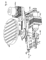
- Fig. 6A the arrangement of the stepping motor 20D for the rotation C of the chuck table 12A and the stepping motor 16D for the adjustment of the chuck table 12A in the X direction can be seen.
- Via toothed belt 20C or 16C and a pulley 20B or a spindle drive 16B (FIG. 6B) the drive connection to the clamping table 12A or to the clamping table housing 36 takes place.
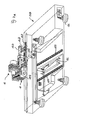
- FIG. 7A shows the position of the stepping motor 18D of the adjusting device 18 and the associated spindle drive 18B for its arrangement on the underside of the base plate 30A.
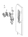
- Fig. 7B can be seen the corresponding structure of the side wall.
- an elongated opening 32 for passing a drive pin into the base plate 30A and an elongate opening 34 in the side wall 30B (both parallel to the guide rails 18A, 22A) for a corresponding drive pin are provided detect.
- the clamping table housing 36 or the drill spindle housing 38 is displaceable overall along the X or Z axis.
Landscapes
- Engineering & Computer Science (AREA)
- Mechanical Engineering (AREA)
- Machine Tool Units (AREA)
- Drilling Tools (AREA)
- Dental Tools And Instruments Or Auxiliary Dental Instruments (AREA)
- Adornments (AREA)
- Drilling And Boring (AREA)
Description
- Die Erfindung betrifft ein Miniatur-Bearbeitungszentrum mit vielachsigem Bohr- oder Fräswerkzeug mit einem Werkstück-Spanntisch, einem Bohr- oder Fräskopf, Verstelleinrichtungen für die verschiedenen Bearbeitungsachsen sowie einem den Werkstück-Spanntisch und den Bohr- oder Fräskopf gemeinsam tragenden Maschinen-Gestell.
- Fünfachsige Bearbeitungszentren werden für komplexe Bohr- und Fräsarbeiten an komplexen Werkstücken angeboten, bei denen, den sehr vielfältigen Anforderungen und hohen Arbeitslasten entsprechend, aufwendige Konstruktionen und starke Antriebe verwendet werden. Selbst auf dem Markt erhältliche sogenannte Mini-Fräsmaschinen benötigen Antriebsleistungen von mehreren kW. Sie weisen äußere Abmessungen in der Größenordnung von einem Meter oder mehr als Breite, Höhe oder Länge auf und besitzen ein erhebliches Gewicht. Eine etwaige Einhausung des Arbeitsraumes führt zu weiterer Gewichtserhöhung und Vergrößerung der Abmessungen. Auch solche Mini-Fräsmaschinen sind außerordentlich kostspielig.
- Die EP 1 402 991 A2 zeigt eine Werkzeugmaschine mit einem auf zwei Führungen verfahrbaren Fahrständer der die horizontale Arbeitsspindel trägt und an Führungen deren Vertikalverlagerung gestattet. Ein Spanntisch 70 ist mittels Führungen 55/56 entlang eines kastenartig ausgeführten Bettes 2 horizontal verfahrbar. Der den Fahrständer tragende ortsfeste Ständer ist mit dem Bett als einteilige Kastenkonstruktion ausgebildet.
- Davon ausgehend liegt der Erfindung die Aufgabe zugrunde, ein Miniatur-Bearbeitungszentrum zu schaffen, welches hinsichtlich der Gesamtabmessungen, des Gewichtes und/oder des Herstellungsaufwandes spürbar günstiger ist und sich für wirtschaftliche Klein- und Kleinst-, Serien- sowie Einzelbearbeitung eignet.
- Diese Aufgabe wird durch ein Miniatur-Bearbeitungszentrum mit dem Merkmal des Anspruchs 1 gelöst. Eine im wesentlichen horizontale Grundplatte trägt den Werkstück-Spanntisch und eine im wesentlichen vertikale Seitenwand trägt den Bohr- oder Fräskopf, wobei ein Versteifungselement zwischen der Seitenwand und der Grundplatte wirksam ist. Ein bevorzugter Lösungsweg besteht darin, den Werkstück-Spanntisch und den Bohr- oder Fräskopf mittels modulartiger Wände einander zuzuordnen.
- Durch die Erfindung wird unter anderem erreicht, dass für eine vielachsige WerkstückBearbeitung die Antriebs- und Verstell-Aggregate aus leicht verfügbaren Standardbauteilen bestehen können, gleichwohl aber eine außerordentlich hohe Bearbeitungspräzision und Reproduzierbarkeit von Bearbeitungsergebnissen erzielt wird, eine Arbeitsraumeinhausung mit besonders geringem Aufwand möglich ist und durch einen modulartigen Aufbau des Maschinengestells und/oder der übrigen Antriebsteile eine hohe Variantenvielfalt nach Maßgabe der Kundenanforderungen zu vergleichsweise erschwinglichen Kosten möglich ist. Femer können sehr energieschonende Antriebe verwendet werden, so dass ein geringes Maschinengewicht, leiser Betrieb und geringe Energiekosten erreicht werden. Ein derartiges Miniatur-Bearbeitungszentrum eignet sich zum Beispiel auch für CNC gesteuerte Bearbeitung im Dentalbereich sowie in vielen anderen Anwendungsfeldern, bei denen es auf hohe Maßpräzision komplexer Oberflächenstrukturen ankommt. Insbesondere sind erfindungsgemäße Miniatur-Bearbeitungszentren zur Fein- oder Endbearbeitung von Präzisionsteilen geeignet, bei denen es nicht auf großen Materialabhub sondern große Abmessungs-Präzision und Reproduzierbarkeit ankommt.
- Die vorgenannten sowie die beanspruchten und in den Ausführungsbeispielen beschriebenen erfindungsgemäß zu verwendenden Bauteile unterliegen in ihrer Größe, Formgestaltung, Materialauswahl und technischen Konzeption keinen besonderen Ausnahmebedingungen, so dass die in dem Anwendungsgebiet bekannten Auswahlkriterien uneingeschränkt Anwendung finden können
- Weitere Einzelheiten, Merkmale und Vorteile des Gegenstandes der Erfindung ergeben sich aus den Unteransprüchen, sowie aus der nachfolgenden Beschreibung der zugehörigen Zeichnung und Tabelle, in der - beispielhaft - Ausführungsbeispiele eines Miniatur-Bearbeitungszentrums mit vielachsigem Bohr- und Fräswerkzeug dargestellt ist.
- In der Zeichnung zeigen:
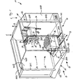
- Fig. 1
- ein Miniatur-Bearbeitungszentrum perspektivisch;
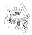
- Fig. 2
- das Miniatur-Bearbeitungszentrum nach Fig. 1 in einer zweiten perspektivischen Ansicht aber ohne Gehäuse;
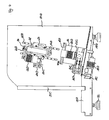
- Fig. 3
- dasselbe Miniatur-Bearbeitungszentrum in Ansicht von vorne (Ansicht A-A gemäß Fig. 1 A) ohne Gehäuse;
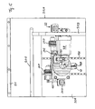
- Fig. 4
- dasselbe Miniatur-Bearbeitungszentrum in linker Seitenansicht (Ansicht B-B gemäß Fig. 1A) ohne Gehäuse, wobei das Maschinengestell durchsichtig (wie aus gläsernen Wänden) dargestellt ist;;
- Fig. 5
- dasselbe Miniatur-Bearbeitungszentrum in Ansicht von oben (Ansicht C-C gemäß Fig. 1 A) ohne Gehäuse;
- Fig. 6A
- von demselben Miniatur-Bearbeitungszentrum den Arbeitstisch in perspektivischer Darstellung ohne Gehäuseteile;
- Fig. 6B
- denselben Arbeitstisch samt Gehäuse im Vertikalschnitt;
- Fig. 7A
- von demselben Miniatur-Bearbeitungszentrum die Grundplatte mit 2 Arbeitstischverstelleinrichtungen als perspektivische Explosionsdarstellung sowie
- Fig.7B
- von demselben Miniatur-Bearbeitungszentrumdie Seitenwände mit 2 Bohr/Fräskopf-Verstelleinrichtungen als perspektivische Explosionsdarstellung.
- Wie aus Figur 1 ersichtlich, besteht ein insgesamt mit 10 bezeichnetes Miniatur-Bearbeitungszentrum aus folgenden Kernbestandteilen: Einem als Arbeitstisch 12 dienenden Werkstück-Spanntisch, einem Bohr- oder Fräskopf 14, Verstelleinrichtungen 16 bis 26 für die verschiedenen Bearbeitungsachsen sowie einem Maschinengestell 30 bestehend aus einer Grundplatte 30A, einer plattenförmigen Seitenwand 30B und einem zwischen der Seitenwand und der Grundplatte wirksamen Versteifungselement 30C. In den dargestellten und insoweit bevorzugten Ausführungsformen definiert das Maschinengestell 30 einen Arbeitsraum, der durch ein Gehäuseteil 40 zu einem geschlossenen Arbeitsraum schließbar ist, wobei das, vorzugsweise durchsichtige, Gehäuseteil 40 aus einer Seitenwand 40B, einer Deckenwand 40A und einer öffen- und schließbaren Frontwand 40C besteht. An den Bearbeitungsraum schließen sich jeweils an den Rückseiten der Seitenwand 30B und des Versteifungselementes 30C Nebenräume 50A und 50B an, die durch weitere, zum Teil durchsichtige Wände geschlossen sind und die Versorgung mit elektrischer Energie, Arbeitsfluiden und Schnittstelle für eine Steuerung beherbergen können.
- Es ist möglich, dass bei identischen Außenabmessungen des Miniatur-Bearbeitungszentrums der Bearbeitungsraum zugunsten bzw. zu Lasten der Nebenräume in seinen Abmessungen verändert werden kann, indem eine in der Zeichnung nicht detailliert dargestellte Möglichkeit zum Verbreitern und/oder Verlängern bzw. zum schmaler Machen und/oder Verkürzen vorgesehen wird (siehe Doppelpfeile D und E in Fig.2), insbesondere durch modulartige Zusammenstellung des Maschinengestells 30. Diese Anpassung an den Bedarfsfall des Kunden kann u.a. durch modulare Adapterstücke im Bereich der Grundplatte erzielt werden.
- Die vielachsige Verstellbarkeit des Bohr- oder Fräswerkzeuges 14A des Bohr- oder Fräskopfes 14, die nachfolgend im Einzelnen noch beschrieben werden wird, umfasst bei den dargestellten und insoweit bevorzugten Ausführungsbeispielen eine sechsachsige Verstellmöglichkeit des Bohr- oder Fräswerkzeuges in Bezug auf das am Arbeitstisch festzuspannende zu bearbeitende Werkstück:
- Eine Verstelleinrichtung 16 gestattet ein Verfahren des Spanntisches 12A in Richtung der X-Koordinate mit einem Verfahrweg von z. B. 120 mm;
- Eine Verstelleinrichtung 18, deren Antrieb in einem Hohlraum auf der Unterseite der Grundplatte 30A angeordnet ist, gestattet das Verfahren des Spanntisches 12A in der Y-Achse mit einem Verfahrweg von z. B. 280 mm;
- Fig. 1 zeigt den Spanntisch 12A in einer Null-Stellung, von der er (in der Zeichnung nach rechts und links) in Extrempositionen der X-Achse verfahrbar ist.
- Eine Verstelleinrichtung 20 gestattet das Verschwenken des Spanntisches 12A um eine flächennormale Achse mit einem insbesondere unbegrenzten Drehwinkel C;
- Eine Verstelleinrichtung 22, deren Antrieb auf der Rückseite der Seitenwand 30B innerhalb des Nebenraumes 50A angeordnet ist, gestattet ein Verstellen des Bohr- oder Fräskopfes in Richtung der Z-Achse bei einem Verfahrweg von z. B. 125 mm;
- Eine Verstelleinrichtung 24 gestattet das Verschwenken des Bohr- oder Fräskopfes 14 um eine im wesentlichen horizontale Achse, z. B. um jeweils 90° zu beiden Seiten der Z-Achse. Größere Verschwenkwinkel A sind aber nicht grundsätzlich ausgeschlossen;
- Eine Verstelleinrichtung 26 gestattet das Verfahren des Bohr- oder Fräswerkzeuges 14A in einer Richtung, die etwa parallel zur Werkzeugachse ist, und gestattet z. B. einen Verfahrweg B von 40 mm;
- Ferner ist ein Bohr- oder Fräsantrieb 28 vorgesehen, der das Bohr- oder Fräswerkzeug 14A, vorzugsweise hochtourig, antreibt. Hohe Drehzahlen von z. B. 10.000 bis 80.000 Umdrehungen pro Minute gestatten es nicht nur, die Antriebskraft gering zu halten, sondern auch die sich entwickelnde Wärme vornehmlich über die abgearbeiteten Werkstückspähne abzuführen. Die völlige Einhausung des Arbeitsraumes ist daher auch aus Gründen der Eindämmung der Staubverbreitung von Vorteil.
- Wie aus Fig. 1 ersichtlich, sind die zueinander rechtwinkligen Koordinaten der X-, Y- und Z-Achsen gegenüber den Aufstandsfüßen 52 des Miniatur-Bearbeitungszentrums um einen gewissen Winkel (in der Zeichnung z. B. um etwa 10°-15° nach vorne) d. h. zur Frontwand 40C hin geneigt. Diese Neigung wird durch eine Schrägstellung der Oberseite der Grundplatte 30A sowie eine dementsprechende Schrägstellung der Führungen des Bohr- oder Fräskopfes 14 in Richtung der Z-Achse an der Seitenwand 30B erreicht. Durch diese Schrägstellung werden Werkstückspähne in einer Vorzugsrichtung zum Wandern und sich Sammeln veranlasst, so dass der Arbeitstisch 12 in gewissem Umfang von solchen Spähnen selbsttätig befreit wird. Außerdem führt die Schrägstellung zu einer Verbesserung der Aufspannbarkeit der Werkstücke. Schließlich wird durch die Schrägstellung der Grundplatte 30A auf deren Unterseite der bereits erwähnte Platz zur Unterbringung des Antriebs der Verstelleinrichtung 18 für die Bewegung des Arbeitstisches in der Y-Achse erreicht. Einige der Verstellantriebe sind also beidseitig des Maschinengestells 30 angeordnet.
- Der plattenförmige Aufbau der Grundplatte 30 A und der Seitenwand 30B erlaubt eine einfache Herstellung und einen einfachen Zusammenbau des Maschinengestells - dies auch in Verbindung mit maßlichen Veränderung nach Kundenwünschen, wie weiter oben dargelegt.
- Die dreidimensionale Aufspannung eines Arbeitsraumes durch die Grundplatte 30A und die Seitenwand 30B und das vorzugsweise als Rückwand ausgebildete Versteifungselement 30C ermöglicht trotz der einfachen Herstellbarkeit des Maschinengestells eine außerordentlich hohe Steifigkeit desselben mit der Folge einer außerordentlich hohen Bearbeitungspräzision. Die hierfür verwendeten Führungsschienen 16A, 18A,... können in Form von Serienbauteilen mit entsprechenden Präzisionsmerkmalen, z. B. durch einfache Schraubverbindungen befestigt werden. Präzisionsspindeln in Verbindung mit Zahnriemen und vergleichsweise leistungsschwachen Schrittmotoren können für jeden der sechs Verstellantriebe Verwendung finden. Sie sind auf dem Markt in guter Auswahl erhältlich und leicht montierbar.
- Auf diese Weise wird bei minimalen Maschinenabmessungen, bei vergleichsweise geringem Gewicht und geringen Antriebskräften ein vielachsiges höchst präzises Miniatur-Bearbeitungszentrum bereitgestellt, dass z. B. über ein Notebook auf einfache Weise gesteuert werden kann.
- Aus Fig. 2 ist anhand von Doppelpfeilen D und E im Prinzip ersichtlich, wie durch Versetzen der Seitenwand 30B und/oder des Versteifungselementes 30C bei vorgegebener Grundgröße des Miniatur-Bearbeitungszentrums die Größe des Bearbeitungsraumes veränderbar ist.
- Aus Fig. 6A ist die Anordnung des Schrittmotors 20D für die Drehung C des Spanntisches 12A und der Schrittmotor 16D für die Verstellung des Spanntisches 12A in X-Richtung ersichtlich. Über Zahnriemen 20C bzw. 16C sowie eine Riemenscheibe 20B bzw. einem Spindeltrieb 16B (Fig. 6B) erfolgt die Antriebsverbindung zum Spanntisch 12A bzw. zum Spanntischgehäuse 36.
- Aus Fig. 7A ist Lage des Schrittmotores 18D der Verstelleinrichtung 18 sowie der zugehörige Spindeltrieb18B für seine Anordnung auf der Unterseite der Grundplatte 30A ersichtlich. In Fig. 7B erkennt man den entsprechenden Aufbau der Seitenwand. Um einen Teil der Antriebe nach außerhalb des Arbeitsraumes zu verlagern, ist in die Grundplatte 30A eine längliche Durchbrechung 32 zum Durchführen eines Antriebszapfens und in der Seitenwand 30B eine längliche Durchbrechung 34 (beide jeweils parallel zu den Führungsschienen 18A, 22A) für einen entsprechenden Antriebszapfen zu erkennen. Dadurch wird das Spanntischgehäuse 36 bzw. das Bohr- Fräspindelgehäuse 38 insgesamt entlang der X- bzw. Z-Achse verlagerbar.
-
- 10
- Miniatur-Bearbeitungszentrum
- 12
- Arbeitstisch
- 12A
- Spanntisch
- 14
- Bohr- oder Fräskopf
- 14A
- Bohr- und Fräswerkzeug
- 16
- Verstelleinrichtung
- 16A
- Führungsschiene
- 16B
- Spindeltrieb
- 16C
- Zahnriemen
- 16D
- Schrittmotor
- 18
- Verstelleinrichtung
- 18A
- Führungsschiene
- 18B
- Spindeltrieb
- 18C
- Zahnriemen
- 18D
- Schrittmotor
- 20
- Verstelleinrichtung
- 20A
- Führung
- 20B
- Riemenscheibe
- 20C
- Zahnriemen
- 20D
- Schrittmotor
- 22
- Verstelleinrichtung
- 22A
- Führungsschiene
- 22B
- Spindeltrieb
- 22C
- Zahnriemen
- 22D
- Schrittmotor
- 24
- Verstelleinrichtung
- 24A
- Führungsschiene
- 24B
- Spindeltrieb
- 24C
- Zahnriemen
- 24D
- Schrittmotor
- 25
- Verstelleinrichtung
- 26A
- Führungsschiene
- 26B
- Spindeltrieb
- 26C
- Zahnriemen
- 26D
- Schrittmotor
- 28
- Bohr- / Fräsantrieb
- 30
- Maschinengestell
- 30A
- Grundplatte
- 30B
- Seitenwand
- 30C
- Versteifungselement
- 32
- Durchbrechung
- 34
- Durchbrechung
- 36
- Spanntischgehäuse
- 36A
- Basisplatte
- 38
- Bohr- /Frässpindelgehäuse
- 40
- Gehäuseteil
- 40A
- Deckenwand
- 40B
- Seitenwand
- 40C
- Frontwand
- 50A
- Nebenraum
- 50B
- Nebenraum
- 51
- Nebenraum - Außenwand
- 52
- Aufstandsfüße
- AA
- Ansicht von vorne
- BB
- Seitenansicht
- CC
- Ansicht von oben
- A
- Schwenkrichtungsdoppelpfeil
- B
- Verfahrrichtungsdoppefpfeil
- C
- Verschwenkrichtungsdoppelpfeil
- D
- Seitenwandverstellung
- E
- Versteifungselementverstellung
Claims (17)
- Miniatur-Bearbeitungszentrum (10) mit vielachsigem Bohr- oder Fräswerkzeug (14A) mit einem als Arbeitstisch (12) dienenden Werkstück-Spanntisch (12A), einem Bohr- oder Fräskopf (14), Verstelleinrichtungen (16, ....., 26) für die verschiedenen Bearbeitungsachsen (X, Y, Z, A, B, C) sowie einem den Werstück-Spanntisch und den Bohr- oder Fräskopf gemeinsam tragenden Maschinengestell (30), bei dem das Maschinengestell (30) ausschließlich aus einer im wesentlichen horizontalen, den Werkstück-Spanntisch tragenden, im wesentlichen plattenförmig gestalteten, Grundplatte (30A), einer im wesentlichen vertikalen, den Bohr- oder Fräskopf tragenden, im wesentlichen plattenförmig gestalteten, Seitenwand (30B) sowie einem zwischen der Seitenwand und der Grundplatte wirksamen Versteifungselement (30C) besteht.
- Miniatur-Bearbeitungsszentrum nach Anspruch 1, gekennzeichnet durch einen modulartigen Aufbau des Maschinengestells (30).
- Miniatur-Bearbeitungsszentrum nach Anspruch 1 oder 2, dadurch gekennzeichnet, dass zumindest ein Antrieb oder ein Teil des Antriebes für das Verfahren des Bohr- oder Fräskopfes auf der Rückseite der Seitenwand (30B) angeordnet ist.
- Miniatur-Bearbeitungsszentrum nach einem der Ansprüche 1 bis 3, dadurch gekennzeichnet, dass zumindest ein Antrieb oder der Teil eines Antriebes für das Verfahren des Spanntisches (12A) auf der Unterseite der Grundplatte (30A) angeordnet ist.
- Miniatur-Bearbeitungsszentrum nach Anspruch 3 oder 4, gekennzeichnet durch eine Durchbrechung (32) in der Grundplatte (30A) und/oder eine Durchbrechung (34) in der Seitenwand (30B).
- Miniatur-Bearbeitungsszentrum nach einem der Ansprüche 1 bis 5, dadurch gekennzeichnet, dass Verstellantriebe für den Spanntisch (12A) und/oder den Bohr- oder Fräskopf (14) beidseitig der Grundplatte (30A) bzw. der Seitenwand (30B) angeordnet sind.
- Miniatur-Bearbeitungsszentrum nach einem der Ansprüche 1 bis 6, dadurch gekennzeichnet, dass das Versteifungselement (30C) als Rückwand ausgebildet ist.
- Miniatur-Bearbeitungsszentrum nach einem der Ansprüche 1 bis 7, dadurch gekennzeichnet, dass die Verstelleinrichtungen (16, ...., 26) zumindest teilweise über Zahnriemen angetriebene Spindeltriebe aufweisen.
- Miniatur-Bearbeitungsszentrum nach einem der Ansprüche 1 bis 8, dadurch gekennzeichnet, dass zumindest ein für eine Verstelleinrichtung (16, ...., 26) vorgesehener Spindeltrieb beidseitig über Zahnriemen antreibbar sind.
- Miniatur-Bearbeitungsszentrum nach einem der Ansprüche 1 bis 3, dadurch gekennzeichnet, dass das Maschinengestell (30) einen Arbeitsraum definiert.
- Miniatur-Bearbeitungsszentrum nach einem der Ansprüche 1 bis 10, gekennzeichnet durch ein Gehäuseteil (40) zum Schließen eines Arbeitsraumes.
- Miniatur-Bearbeitungsszentrum nach Anspruch 11, dadurch gekennzeichnet, dass die Wände des Gehäuseteils (40) zumindest teilweise durchsichtig sind.
- Miniatur-Bearbeitungsszentrum nach einem der Ansprüche 1 bis 12, gekennzeichnet durch mindestens einen seitlich des Arbeitsraumes angeordneten Nebenraum (50A; 50B).
- Miniatur-Bearbeitungsszentrum nach einem der Ansprüche 1 bis 13, dadurch gekennzeichnet, dass die Seitenwand (30B) und /oder das Versteifungselement (30C) unter Vergrößern oder Verkleinern des Arbeitsraumes versetzbar ist.
- Miniatur-Bearbeitungsszentrum nach Anspruch 14, gekennzeichnet durch mindestens ein modulares Adapterstück im Bereich der Grundplatte.
- Miniatur-Bearbeitungsszentrum nach einem der Ansprüche 1 bis 15, dadurch gekennzeichnet, dass die Grundplatte (30A) gegenüber der Horizontalen schräg gestellt ist.
- Miniatur-Bearbeitungsszentrum nach einem der Ansprüche 1 bis 16, dadurch gekennzeichnet, dass die Führungen des Bohr-/ Fräskopfes (14) zum Verfahren desselben in Z-Richtung gegenüber der Vertikalen schräg gestellt sind.
Applications Claiming Priority (1)
| Application Number | Priority Date | Filing Date | Title |
|---|---|---|---|
| DE202004016057U DE202004016057U1 (de) | 2004-10-16 | 2004-10-16 | Miniatur-Bearbeitungszentrum mit vielachsigem Bohr- und Fräswerkzeug |
Publications (2)
| Publication Number | Publication Date |
|---|---|
| EP1647354A1 EP1647354A1 (de) | 2006-04-19 |
| EP1647354B1 true EP1647354B1 (de) | 2007-02-07 |
Family
ID=35717554
Family Applications (1)
| Application Number | Title | Priority Date | Filing Date |
|---|---|---|---|
| EP05022204A Ceased EP1647354B1 (de) | 2004-10-16 | 2005-10-12 | Miniatur-Bearbeitungszentrum mit vielachsigem Bohr-oder Fräswerkzeug |
Country Status (3)
| Country | Link |
|---|---|
| EP (1) | EP1647354B1 (de) |
| AT (1) | ATE353265T1 (de) |
| DE (2) | DE202004016057U1 (de) |
Cited By (2)
| Publication number | Priority date | Publication date | Assignee | Title |
|---|---|---|---|---|
| DE202008013235U1 (de) | 2008-10-08 | 2010-03-04 | Kämmerer, Sigrid | Bearbeitungszentrum mit Werkzeugwechsler, Werkzeugwechsler für ein Bearbeitungszentrum sowie Werkzeugmagazin für ein Bearbeitungszentrum mit Werkzeugwechsler |
| DE202016105167U1 (de) | 2016-09-16 | 2017-12-20 | Zorn Microsolution Gmbh | Transportable Werkstück-Bearbeitungsvorrichtung |
Families Citing this family (7)
| Publication number | Priority date | Publication date | Assignee | Title |
|---|---|---|---|---|
| DE202014007224U1 (de) * | 2014-09-11 | 2015-12-14 | Sauer Gmbh | Werkzeugmaschine |
| CN105397502A (zh) * | 2015-12-26 | 2016-03-16 | 哈尔滨和谐旺科技开发有限公司 | 一种数控机床底座 |
| CN107214565B (zh) * | 2016-03-22 | 2024-07-05 | 北京蓝新特科技股份公司 | 万能夹具机床 |
| CN108274238B (zh) * | 2018-04-03 | 2024-02-27 | 内江金鸿曲轴有限公司 | 一种用于钻中心孔兼套车外圆的机床 |
| CN108655758B (zh) * | 2018-05-05 | 2020-09-08 | 台州鑫贝汽车零部件有限公司 | 一种便于移动的工业车床 |
| CN110524038B (zh) * | 2019-10-11 | 2022-01-04 | 湖南省晨晟机械制造有限公司 | 一种自动高效散热控制的铣床 |
| CN119457201A (zh) * | 2024-11-28 | 2025-02-18 | 江苏爱吉斯海珠机械有限公司 | 一种气缸套生产系统中的立式升降台铣床 |
Family Cites Families (8)
| Publication number | Priority date | Publication date | Assignee | Title |
|---|---|---|---|---|
| FR1008511A (fr) * | 1947-09-11 | 1952-05-19 | Hommel G M B H H | Appareil universel d'usinage |
| DE4230502C1 (de) * | 1992-09-14 | 1994-03-10 | Steinel Bernhard Werkzeugmasch | Maschinengestell für ein Bearbeitungszentrum |
| DE4441252B4 (de) * | 1994-11-19 | 2006-01-26 | Maschinenfabrik Berthold Hermle Ag | Werkzeugmaschine, insbesondere Bohr- und Fräsmaschine |
| DE29701374U1 (de) * | 1997-01-28 | 1997-03-27 | Habel, Klaus, 22885 Barsbüttel | Heimwerkerbearbeitungseinrichtung |
| DE10012445A1 (de) * | 2000-03-15 | 2001-09-27 | Hubert Haller | Bearbeitungszentrum |
| DE10141865B4 (de) * | 2001-08-27 | 2006-02-02 | Deckel Maho Pfronten Gmbh | Programmgesteuerte Universal-Fräs- und Bohrmaschine |
| DE50204316D1 (de) * | 2001-10-30 | 2006-02-02 | Teamtechnik Maschinen Und Anla | Zentralkammer |
| DE10245058B4 (de) * | 2002-09-26 | 2005-05-25 | Kurt Kessler | Programmgesteuerte Werkzeugmaschine |
-
2004
- 2004-10-16 DE DE202004016057U patent/DE202004016057U1/de not_active Expired - Lifetime
-
2005
- 2005-10-12 AT AT05022204T patent/ATE353265T1/de not_active IP Right Cessation
- 2005-10-12 DE DE502005000367T patent/DE502005000367D1/de not_active Expired - Lifetime
- 2005-10-12 EP EP05022204A patent/EP1647354B1/de not_active Ceased
Cited By (3)
| Publication number | Priority date | Publication date | Assignee | Title |
|---|---|---|---|---|
| DE202008013235U1 (de) | 2008-10-08 | 2010-03-04 | Kämmerer, Sigrid | Bearbeitungszentrum mit Werkzeugwechsler, Werkzeugwechsler für ein Bearbeitungszentrum sowie Werkzeugmagazin für ein Bearbeitungszentrum mit Werkzeugwechsler |
| DE202016105167U1 (de) | 2016-09-16 | 2017-12-20 | Zorn Microsolution Gmbh | Transportable Werkstück-Bearbeitungsvorrichtung |
| EP3296057A1 (de) | 2016-09-16 | 2018-03-21 | Zorn microsolution GmbH | Transportable werkstück-bearbeitungsvorrichtung |
Also Published As
| Publication number | Publication date |
|---|---|
| DE502005000367D1 (de) | 2007-03-22 |
| ATE353265T1 (de) | 2007-02-15 |
| DE202004016057U1 (de) | 2006-02-23 |
| EP1647354A1 (de) | 2006-04-19 |
Similar Documents
| Publication | Publication Date | Title |
|---|---|---|
| EP1882544B1 (de) | Fräs- und Bohrmaschine | |
| DE4495551C2 (de) | Z-Achsen-Antrieb für eine Werkzeugmaschine | |
| EP0721819B1 (de) | Werkzeugmaschine | |
| DE10061934B4 (de) | Werkzeugmaschine zur spanenden Werkstückbearbeitung | |
| EP2658676B1 (de) | Programmgesteuerte werkzeugmaschine | |
| DE19650360A1 (de) | Antriebseinheit für eine Maschine | |
| DE4230502C1 (de) | Maschinengestell für ein Bearbeitungszentrum | |
| DE20119608U1 (de) | 5-Achsen-Portalwerkzeugmaschine in Parallelbauweise | |
| EP1402991A2 (de) | Werkzeugmaschine mit einem auf zwei Führungen mit insgesamt drei Auflagern verfahrbarem Fahrständer | |
| EP1645359B1 (de) | Werkzeugmaschine | |
| DE102007022200A1 (de) | Multiples System für den Wechsel der Werkzeuge in einer Maschine zur Holzbearbeitung | |
| EP0565050A1 (de) | Fräskopf | |
| EP1647354A1 (de) | Miniatur-Bearbeitungszentrum mit vielachsigem Bohr-oder Fräswerkzeug | |
| DE2216401A1 (de) | Universalbohr- und -fraesmaschine mit mehreren auswechselbaren werkzeugkoepfen | |
| EP0472979B1 (de) | Werkzeugmaschine zur Bearbeitung flächiger Werkstücke | |
| DE3207873C2 (de) | Vorrichtung zum Bohren oder Fräsen von Werkstücken aus Holz, Holzwerkstoffen oder Kunststoff | |
| EP0328034A2 (de) | Werkzeug-Schleifmaschine | |
| EP0307830B1 (de) | Antriebsvorrichtung für eine Bewegungseinheit einer Werkzeugmaschine | |
| EP1166952B1 (de) | NC-gesteuerte Portalfräsmaschine | |
| DE10302985A1 (de) | Bearbeitungszentrum | |
| DE10106189B4 (de) | Werkzeugmaschine | |
| DE2705628C2 (de) | Aufbau-Werkzeugmaschine | |
| DE20023287U1 (de) | Werkzeugmaschine zur spanenden Werkstückbearbeitung | |
| EP0949042B1 (de) | Werkzeugmaschine, insbesondere Bohr- und Fräsmaschine | |
| DE3414886C1 (de) | Werkzeugmaschine |
Legal Events
| Date | Code | Title | Description |
|---|---|---|---|
| PUAI | Public reference made under article 153(3) epc to a published international application that has entered the european phase |
Free format text: ORIGINAL CODE: 0009012 |
|
| AK | Designated contracting states |
Kind code of ref document: A1 Designated state(s): AT BE BG CH CY CZ DE DK EE ES FI FR GB GR HU IE IS IT LI LT LU LV MC NL PL PT RO SE SI SK TR |
|
| AX | Request for extension of the european patent |
Extension state: AL BA HR MK YU |
|
| 17P | Request for examination filed |
Effective date: 20060629 |
|
| GRAP | Despatch of communication of intention to grant a patent |
Free format text: ORIGINAL CODE: EPIDOSNIGR1 |
|
| RAP1 | Party data changed (applicant data changed or rights of an application transferred) |
Owner name: KAEMMERER, SIGRID |
|
| AKX | Designation fees paid |
Designated state(s): AT BE BG CH CY CZ DE DK EE ES FI FR GB GR HU IE IS IT LI LT LU LV MC NL PL PT RO SE SI SK TR |
|
| GRAS | Grant fee paid |
Free format text: ORIGINAL CODE: EPIDOSNIGR3 |
|
| GRAA | (expected) grant |
Free format text: ORIGINAL CODE: 0009210 |
|
| AK | Designated contracting states |
Kind code of ref document: B1 Designated state(s): AT BE BG CH CY CZ DE DK EE ES FI FR GB GR HU IE IS IT LI LT LU LV MC NL PL PT RO SE SI SK TR |
|
| PG25 | Lapsed in a contracting state [announced via postgrant information from national office to epo] |
Ref country code: FI Free format text: LAPSE BECAUSE OF FAILURE TO SUBMIT A TRANSLATION OF THE DESCRIPTION OR TO PAY THE FEE WITHIN THE PRESCRIBED TIME-LIMIT Effective date: 20070207 Ref country code: PL Free format text: LAPSE BECAUSE OF FAILURE TO SUBMIT A TRANSLATION OF THE DESCRIPTION OR TO PAY THE FEE WITHIN THE PRESCRIBED TIME-LIMIT Effective date: 20070207 Ref country code: IE Free format text: LAPSE BECAUSE OF FAILURE TO SUBMIT A TRANSLATION OF THE DESCRIPTION OR TO PAY THE FEE WITHIN THE PRESCRIBED TIME-LIMIT Effective date: 20070207 Ref country code: SI Free format text: LAPSE BECAUSE OF FAILURE TO SUBMIT A TRANSLATION OF THE DESCRIPTION OR TO PAY THE FEE WITHIN THE PRESCRIBED TIME-LIMIT Effective date: 20070207 Ref country code: DK Free format text: LAPSE BECAUSE OF FAILURE TO SUBMIT A TRANSLATION OF THE DESCRIPTION OR TO PAY THE FEE WITHIN THE PRESCRIBED TIME-LIMIT Effective date: 20070207 |
|
| REG | Reference to a national code |
Ref country code: GB Ref legal event code: FG4D Free format text: NOT ENGLISH |
|
| REG | Reference to a national code |
Ref country code: CH Ref legal event code: EP |
|
| REG | Reference to a national code |
Ref country code: IE Ref legal event code: FG4D Free format text: LANGUAGE OF EP DOCUMENT: GERMAN |
|
| REF | Corresponds to: |
Ref document number: 502005000367 Country of ref document: DE Date of ref document: 20070322 Kind code of ref document: P |
|
| GBT | Gb: translation of ep patent filed (gb section 77(6)(a)/1977) |
Effective date: 20070411 |
|
| PG25 | Lapsed in a contracting state [announced via postgrant information from national office to epo] |
Ref country code: SE Free format text: LAPSE BECAUSE OF FAILURE TO SUBMIT A TRANSLATION OF THE DESCRIPTION OR TO PAY THE FEE WITHIN THE PRESCRIBED TIME-LIMIT Effective date: 20070507 Ref country code: BG Free format text: LAPSE BECAUSE OF FAILURE TO SUBMIT A TRANSLATION OF THE DESCRIPTION OR TO PAY THE FEE WITHIN THE PRESCRIBED TIME-LIMIT Effective date: 20070507 |
|
| PG25 | Lapsed in a contracting state [announced via postgrant information from national office to epo] |
Ref country code: ES Free format text: LAPSE BECAUSE OF FAILURE TO SUBMIT A TRANSLATION OF THE DESCRIPTION OR TO PAY THE FEE WITHIN THE PRESCRIBED TIME-LIMIT Effective date: 20070518 |
|
| PG25 | Lapsed in a contracting state [announced via postgrant information from national office to epo] |
Ref country code: IS Free format text: LAPSE BECAUSE OF FAILURE TO SUBMIT A TRANSLATION OF THE DESCRIPTION OR TO PAY THE FEE WITHIN THE PRESCRIBED TIME-LIMIT Effective date: 20070607 |
|
| PG25 | Lapsed in a contracting state [announced via postgrant information from national office to epo] |
Ref country code: PT Free format text: LAPSE BECAUSE OF FAILURE TO SUBMIT A TRANSLATION OF THE DESCRIPTION OR TO PAY THE FEE WITHIN THE PRESCRIBED TIME-LIMIT Effective date: 20070709 |
|
| ET | Fr: translation filed | ||
| REG | Reference to a national code |
Ref country code: IE Ref legal event code: FD4D |
|
| PG25 | Lapsed in a contracting state [announced via postgrant information from national office to epo] |
Ref country code: SK Free format text: LAPSE BECAUSE OF FAILURE TO SUBMIT A TRANSLATION OF THE DESCRIPTION OR TO PAY THE FEE WITHIN THE PRESCRIBED TIME-LIMIT Effective date: 20070207 |
|
| PLBE | No opposition filed within time limit |
Free format text: ORIGINAL CODE: 0009261 |
|
| STAA | Information on the status of an ep patent application or granted ep patent |
Free format text: STATUS: NO OPPOSITION FILED WITHIN TIME LIMIT |
|
| PG25 | Lapsed in a contracting state [announced via postgrant information from national office to epo] |
Ref country code: CZ Free format text: LAPSE BECAUSE OF FAILURE TO SUBMIT A TRANSLATION OF THE DESCRIPTION OR TO PAY THE FEE WITHIN THE PRESCRIBED TIME-LIMIT Effective date: 20070207 Ref country code: RO Free format text: LAPSE BECAUSE OF FAILURE TO SUBMIT A TRANSLATION OF THE DESCRIPTION OR TO PAY THE FEE WITHIN THE PRESCRIBED TIME-LIMIT Effective date: 20070207 |
|
| 26N | No opposition filed |
Effective date: 20071108 |
|
| PG25 | Lapsed in a contracting state [announced via postgrant information from national office to epo] |
Ref country code: LV Free format text: LAPSE BECAUSE OF FAILURE TO SUBMIT A TRANSLATION OF THE DESCRIPTION OR TO PAY THE FEE WITHIN THE PRESCRIBED TIME-LIMIT Effective date: 20070207 |
|
| REG | Reference to a national code |
Ref country code: CH Ref legal event code: NV Representative=s name: E. BLUM & CO. AG PATENT- UND MARKENANWAELTE VSP |
|
| PG25 | Lapsed in a contracting state [announced via postgrant information from national office to epo] |
Ref country code: LT Free format text: LAPSE BECAUSE OF FAILURE TO SUBMIT A TRANSLATION OF THE DESCRIPTION OR TO PAY THE FEE WITHIN THE PRESCRIBED TIME-LIMIT Effective date: 20070207 |
|
| BERE | Be: lapsed |
Owner name: KAMMERER, SIGRID Effective date: 20071031 |
|
| PG25 | Lapsed in a contracting state [announced via postgrant information from national office to epo] |
Ref country code: GR Free format text: LAPSE BECAUSE OF FAILURE TO SUBMIT A TRANSLATION OF THE DESCRIPTION OR TO PAY THE FEE WITHIN THE PRESCRIBED TIME-LIMIT Effective date: 20070508 |
|
| PG25 | Lapsed in a contracting state [announced via postgrant information from national office to epo] |
Ref country code: MC Free format text: LAPSE BECAUSE OF NON-PAYMENT OF DUE FEES Effective date: 20071031 |
|
| PG25 | Lapsed in a contracting state [announced via postgrant information from national office to epo] |
Ref country code: BE Free format text: LAPSE BECAUSE OF NON-PAYMENT OF DUE FEES Effective date: 20071031 |
|
| PG25 | Lapsed in a contracting state [announced via postgrant information from national office to epo] |
Ref country code: EE Free format text: LAPSE BECAUSE OF FAILURE TO SUBMIT A TRANSLATION OF THE DESCRIPTION OR TO PAY THE FEE WITHIN THE PRESCRIBED TIME-LIMIT Effective date: 20070207 |
|
| PG25 | Lapsed in a contracting state [announced via postgrant information from national office to epo] |
Ref country code: AT Free format text: LAPSE BECAUSE OF NON-PAYMENT OF DUE FEES Effective date: 20071012 |
|
| PG25 | Lapsed in a contracting state [announced via postgrant information from national office to epo] |
Ref country code: CY Free format text: LAPSE BECAUSE OF FAILURE TO SUBMIT A TRANSLATION OF THE DESCRIPTION OR TO PAY THE FEE WITHIN THE PRESCRIBED TIME-LIMIT Effective date: 20070207 |
|
| PG25 | Lapsed in a contracting state [announced via postgrant information from national office to epo] |
Ref country code: LU Free format text: LAPSE BECAUSE OF NON-PAYMENT OF DUE FEES Effective date: 20071012 |
|
| PG25 | Lapsed in a contracting state [announced via postgrant information from national office to epo] |
Ref country code: HU Free format text: LAPSE BECAUSE OF FAILURE TO SUBMIT A TRANSLATION OF THE DESCRIPTION OR TO PAY THE FEE WITHIN THE PRESCRIBED TIME-LIMIT Effective date: 20070808 Ref country code: TR Free format text: LAPSE BECAUSE OF FAILURE TO SUBMIT A TRANSLATION OF THE DESCRIPTION OR TO PAY THE FEE WITHIN THE PRESCRIBED TIME-LIMIT Effective date: 20070207 |
|
| REG | Reference to a national code |
Ref country code: FR Ref legal event code: PLFP Year of fee payment: 11 |
|
| REG | Reference to a national code |
Ref country code: DE Ref legal event code: R082 Ref document number: 502005000367 Country of ref document: DE Representative=s name: GROSSE, SCHUMACHER, KNAUER, VON HIRSCHHAUSEN, DE Ref country code: DE Ref legal event code: R081 Ref document number: 502005000367 Country of ref document: DE Owner name: INPOTRON SCHALTNETZTEILE GMBH, DE Free format text: FORMER OWNER: KAEMMERER, SIGRID, 47574 GOCH, DE Ref country code: DE Ref legal event code: R082 Ref document number: 502005000367 Country of ref document: DE Representative=s name: PATENTANWAELTE BEHRMANN WAGNER PARTNERSCHAFTSG, DE |
|
| REG | Reference to a national code |
Ref country code: CH Ref legal event code: PUE Owner name: INPOTRON SCHALTNETZTEILE GMBH, DE Free format text: FORMER OWNER: PVM MIKROTECHNIK GMBH, DE Ref country code: CH Ref legal event code: PUE Owner name: PVM MIKROTECHNIK GMBH, DE Free format text: FORMER OWNER: KAEMMERER, SIGRID, DE |
|
| PGFP | Annual fee paid to national office [announced via postgrant information from national office to epo] |
Ref country code: IT Payment date: 20151028 Year of fee payment: 11 |
|
| REG | Reference to a national code |
Ref country code: GB Ref legal event code: 732E Free format text: REGISTERED BETWEEN 20160107 AND 20160113 |
|
| REG | Reference to a national code |
Ref country code: FR Ref legal event code: TP Owner name: INPOTRON SCHALTNETZTEILE GMBH, DE Effective date: 20160217 |
|
| REG | Reference to a national code |
Ref country code: NL Ref legal event code: PD Owner name: INPOTRON SCHALTNETZTEILE GMBH; DE Free format text: DETAILS ASSIGNMENT: VERANDERING VAN EIGENAAR(S), OVERDRACHT; FORMER OWNER NAME: SIGRID KAEMMERER Effective date: 20151209 |
|
| REG | Reference to a national code |
Ref country code: DE Ref legal event code: R082 Ref document number: 502005000367 Country of ref document: DE Representative=s name: PATENTANWAELTE BEHRMANN WAGNER PARTNERSCHAFTSG, DE |
|
| REG | Reference to a national code |
Ref country code: FR Ref legal event code: PLFP Year of fee payment: 12 |
|
| REG | Reference to a national code |
Ref country code: FR Ref legal event code: PLFP Year of fee payment: 13 |
|
| PG25 | Lapsed in a contracting state [announced via postgrant information from national office to epo] |
Ref country code: IT Free format text: LAPSE BECAUSE OF NON-PAYMENT OF DUE FEES Effective date: 20161012 |
|
| REG | Reference to a national code |
Ref country code: FR Ref legal event code: PLFP Year of fee payment: 14 |
|
| PGFP | Annual fee paid to national office [announced via postgrant information from national office to epo] |
Ref country code: NL Payment date: 20181022 Year of fee payment: 14 |
|
| PGFP | Annual fee paid to national office [announced via postgrant information from national office to epo] |
Ref country code: DE Payment date: 20181029 Year of fee payment: 14 |
|
| PGFP | Annual fee paid to national office [announced via postgrant information from national office to epo] |
Ref country code: GB Payment date: 20181025 Year of fee payment: 14 Ref country code: CH Payment date: 20181025 Year of fee payment: 14 Ref country code: FR Payment date: 20181023 Year of fee payment: 14 |
|
| REG | Reference to a national code |
Ref country code: DE Ref legal event code: R119 Ref document number: 502005000367 Country of ref document: DE |
|
| REG | Reference to a national code |
Ref country code: CH Ref legal event code: PL |
|
| REG | Reference to a national code |
Ref country code: NL Ref legal event code: MM Effective date: 20191101 |
|
| PG25 | Lapsed in a contracting state [announced via postgrant information from national office to epo] |
Ref country code: CH Free format text: LAPSE BECAUSE OF NON-PAYMENT OF DUE FEES Effective date: 20191031 Ref country code: LI Free format text: LAPSE BECAUSE OF NON-PAYMENT OF DUE FEES Effective date: 20191031 Ref country code: DE Free format text: LAPSE BECAUSE OF NON-PAYMENT OF DUE FEES Effective date: 20200501 |
|
| PG25 | Lapsed in a contracting state [announced via postgrant information from national office to epo] |
Ref country code: NL Free format text: LAPSE BECAUSE OF NON-PAYMENT OF DUE FEES Effective date: 20191101 |
|
| GBPC | Gb: european patent ceased through non-payment of renewal fee |
Effective date: 20191012 |
|
| PG25 | Lapsed in a contracting state [announced via postgrant information from national office to epo] |
Ref country code: FR Free format text: LAPSE BECAUSE OF NON-PAYMENT OF DUE FEES Effective date: 20191031 Ref country code: GB Free format text: LAPSE BECAUSE OF NON-PAYMENT OF DUE FEES Effective date: 20191012 |