EP1650352A1 - Ecarteur pour glissière de sécurité - Google Patents
Ecarteur pour glissière de sécurité Download PDFInfo
- Publication number
- EP1650352A1 EP1650352A1 EP05450172A EP05450172A EP1650352A1 EP 1650352 A1 EP1650352 A1 EP 1650352A1 EP 05450172 A EP05450172 A EP 05450172A EP 05450172 A EP05450172 A EP 05450172A EP 1650352 A1 EP1650352 A1 EP 1650352A1
- Authority
- EP
- European Patent Office
- Prior art keywords
- intermediate piece
- web
- holes
- legs
- keyhole
- Prior art date
- Legal status (The legal status is an assumption and is not a legal conclusion. Google has not performed a legal analysis and makes no representation as to the accuracy of the status listed.)
- Withdrawn
Links
- 125000006850 spacer group Chemical group 0.000 title abstract description 9
- 230000004888 barrier function Effects 0.000 title 1
- 229910000831 Steel Inorganic materials 0.000 description 4
- 239000010959 steel Substances 0.000 description 4
- 238000013016 damping Methods 0.000 description 2
- 238000010276 construction Methods 0.000 description 1
- 230000001419 dependent effect Effects 0.000 description 1
- 230000003116 impacting effect Effects 0.000 description 1
- 239000002184 metal Substances 0.000 description 1
- 230000002265 prevention Effects 0.000 description 1
Images


Classifications
-
- E—FIXED CONSTRUCTIONS
- E01—CONSTRUCTION OF ROADS, RAILWAYS, OR BRIDGES
- E01F—ADDITIONAL WORK, SUCH AS EQUIPPING ROADS OR THE CONSTRUCTION OF PLATFORMS, HELICOPTER LANDING STAGES, SIGNS, SNOW FENCES, OR THE LIKE
- E01F15/00—Safety arrangements for slowing, redirecting or stopping errant vehicles, e.g. guard posts or bollards; Arrangements for reducing damage to roadside structures due to vehicular impact
- E01F15/02—Continuous barriers extending along roads or between traffic lanes
- E01F15/04—Continuous barriers extending along roads or between traffic lanes essentially made of longitudinal beams or rigid strips supported above ground at spaced points
- E01F15/0407—Metal rails
- E01F15/0438—Spacers between rails and posts, e.g. energy-absorbing means
Definitions
- the invention relates to an intermediate piece for guide devices, as it is used to attach a guardrail band ("guard rail”) to stands.
- Such spacers are known in various embodiments and have the task to take over a certain part of the deformation work on impact of a vehicle against the guide.
- a known intermediate piece as described in AT 409 275 B, has a substantially tubular shape and is connected by screws to the post, wherein the holes in the tubular intermediate piece are keyhole-shaped, and the wider part of the keyhole-like openings in the Position of use of the intermediate piece is arranged below the narrower part.
- deformable spacers for baffles known from AT 409 275 B have been well proven, but do not allow the guardrail to move upwardly upon impact of a vehicle with the baffle, allowing for safe vehicle capture and prevention of overrun the guide is essential.
- the invention is based on the object to provide a deformable intermediate piece of the type mentioned, which allows the movement of the guardrail band upwards.
- the guardrail can move up the impact of a vehicle, since the strap with his legs in the manner of a Parallelogram are deformable.
- the intermediate piece in the web of the intermediate piece according to the invention for receiving screws which connect the intermediate piece with the post, keyhole-like holes are provided which point with their wider part downwards, so that it is possible that the Intermediate piece releases from the upright when it is bent under the action of an impacting vehicle.
- the intermediate piece can move with its bridge along the uprights. As soon as the heads of the screws which connect the intermediate piece to the upright have reached the wider part of the keyhole-like holes, the intermediate piece can become detached from the upright, and the guardrail band is not pulled down by the wegkippenden post.
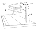
- FIG. 1 shows a section of a guide device with a guide rail band which is fastened to stators via intermediate pieces according to the invention
- FIG. 2 shows an embodiment of a guide device for mounting on structures such as bridges or the like
- FIG. 3 shows the guide device from FIG. 1 in an exploded view
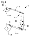
- Fig. 4 shows an inventive intermediate piece in an oblique view.
- a guide device 2 shown in Fig. 1 consists of a guardrail 4 of wave-shaped profiled sheet steel, which is fixed via spacers 6 to vertical, rammed into the ground stanchions 8.
- the uprights 8 may have, for example, the form known from AT 004 690 U1 ("V-pillars").
- the guide 2 is arranged on a building and it are the uprights 8 with shorter distances from each other than in the embodiment shown in Fig. 1 on the edge beam (also "cap") of the construction as a bridge over with the stators 8 welded base plates 10 secured by anchor 11.
- the guardrail 4 is fastened to the uprights 8 consisting of corrugated-profiled sheet steel via the intermediate pieces 6 according to the invention. Below the guardrail 4 is on the stadia 8 attached a slide 12.
- the guard rail 4 is formed of juxtaposed, wavy profiled steel sheets, which are connected to each other at the joints via a plurality of screws. Some of these connecting the parts of the guardrail 4 together screws also serve to connect the guardrail 4 with the spacers 6. For this purpose, at the free ends of the legs 20, 21 of the substantially U-shaped intermediate piece 6 bends 23, 24 are provided with through holes 25 for receiving the connecting screws. In this case, the arrangement is such that the guard rail 4 projects beyond the intermediate pieces 6 down.
- the intermediate piece 6 consists for example of metal, in particular steel, and has the shape shown in detail in FIG. 4 with a web 26 and projecting therefrom two legs 20, 21 which protrude from the web 26 at oblique angles. It is preferred that the upper leg 20 includes a larger angle with the web 26 than the lower leg 21.
- the intermediate piece 6 which connects the guard rail 4 to the uprights 8, initially deformed parallelogram, so that the impact is damped.
- the deformation of the intermediate piece 6 takes place in such a way that the two legs 20, 21 of the acting as a damping bracket intermediate piece 6 pivot upward, so that the Guard rail 4 is raised, which is the security against overrunning the guide 2 is increased.
- the post 10 will move from its vertical position to an oblique position, ie pivot away from the road. During this movement, the web 26 of the intermediate piece 6 slides along the wall of the post 8 facing it.
- An intermediate piece 6 for connecting a guard rail 4 to a post 10 of a guide 2 has a substantially U-shaped form.
- the web 26 of the intermediate piece 6 is connected to the post 10 of the guide 2 by screws.
- the rails, which form the guard rail 4 are attached to the free ends 23, 24 of the two legs 20, 21 of the intermediate piece 6.
- the legs 20, 21 of the intermediate piece 6 close to the web 26 of the intermediate piece 6 oblique angle and have in the position of use from the upright 8 away obliquely upwards.
- In the web 26 of the intermediate piece 6 at least two keyhole-shaped holes 28 are provided for receiving connecting bolts.
- the connecting screws are provided in the assembled state in the narrower region 32 of the keyhole-shaped holes 28.
Landscapes
- Engineering & Computer Science (AREA)
- Architecture (AREA)
- Civil Engineering (AREA)
- Structural Engineering (AREA)
- Refuge Islands, Traffic Blockers, Or Guard Fence (AREA)
Applications Claiming Priority (1)
| Application Number | Priority Date | Filing Date | Title |
|---|---|---|---|
| AT0077504U AT8458U1 (de) | 2004-10-25 | 2004-10-25 | Zwischenstück für leiteinrichtungen |
Publications (1)
| Publication Number | Publication Date |
|---|---|
| EP1650352A1 true EP1650352A1 (fr) | 2006-04-26 |
Family
ID=35613830
Family Applications (1)
| Application Number | Title | Priority Date | Filing Date |
|---|---|---|---|
| EP05450172A Withdrawn EP1650352A1 (fr) | 2004-10-25 | 2005-10-13 | Ecarteur pour glissière de sécurité |
Country Status (2)
| Country | Link |
|---|---|
| EP (1) | EP1650352A1 (fr) |
| AT (1) | AT8458U1 (fr) |
Cited By (9)
| Publication number | Priority date | Publication date | Assignee | Title |
|---|---|---|---|---|
| EP1777346A1 (fr) * | 2005-10-20 | 2007-04-25 | Voest-Alpine Krems Finaltechnik GmbH | Dispositif pour la montage d'une glissière de sécurité |
| KR100855231B1 (ko) | 2007-12-13 | 2008-09-01 | 경갑수 | 충격흡수용 가드레일 |
| EP2048287A1 (fr) * | 2007-10-12 | 2009-04-15 | SOLOSAR Sarl | Écarteur pour glissière de sécurité |
| EP2439340A2 (fr) | 2010-10-11 | 2012-04-11 | Asa-Protect Entwicklungs GmbH | Système de barrière de sécurité |
| AT513840B1 (de) * | 2013-04-19 | 2014-08-15 | Voestalpine Strassensicherheit Gmbh | Fahrzeugrückhaltesystem |
| EP2450489A3 (fr) * | 2010-10-15 | 2016-07-13 | Juan José María González Uriarte | Ancrage pour système de protection de motocycliste |
| IT202100011477A1 (it) * | 2021-05-05 | 2022-11-05 | Anas S P A | Barriera stradale di sicurezza a sezione ridotta per impiego su arginelli ridotti |
| GB2639282A (en) * | 2024-03-11 | 2025-09-17 | Tata Steel Uk Ltd | A crash barrier, method of production and method of installation thereof |
| WO2025191261A1 (fr) * | 2024-03-11 | 2025-09-18 | Tata Steel Uk Limited | Barrière de sécurité, son procédé de production et son procédé d'installation |
Citations (3)
| Publication number | Priority date | Publication date | Assignee | Title |
|---|---|---|---|---|
| FR2124828A5 (fr) * | 1971-01-27 | 1972-09-22 | Vmw Ranshofen Berndorf Ag | |
| EP0810325A2 (fr) * | 1996-05-30 | 1997-12-03 | Autostrada del Brennero S.p.A. | Barrière routière métallique déformable de haute performance |
| EP1367178A1 (fr) * | 2003-07-11 | 2003-12-03 | Karl-Heinz Waidele | Système de retenue pour véhicule avec isolation acoustique |
-
2004
- 2004-10-25 AT AT0077504U patent/AT8458U1/de not_active IP Right Cessation
-
2005
- 2005-10-13 EP EP05450172A patent/EP1650352A1/fr not_active Withdrawn
Patent Citations (3)
| Publication number | Priority date | Publication date | Assignee | Title |
|---|---|---|---|---|
| FR2124828A5 (fr) * | 1971-01-27 | 1972-09-22 | Vmw Ranshofen Berndorf Ag | |
| EP0810325A2 (fr) * | 1996-05-30 | 1997-12-03 | Autostrada del Brennero S.p.A. | Barrière routière métallique déformable de haute performance |
| EP1367178A1 (fr) * | 2003-07-11 | 2003-12-03 | Karl-Heinz Waidele | Système de retenue pour véhicule avec isolation acoustique |
Cited By (13)
| Publication number | Priority date | Publication date | Assignee | Title |
|---|---|---|---|---|
| EP1777346A1 (fr) * | 2005-10-20 | 2007-04-25 | Voest-Alpine Krems Finaltechnik GmbH | Dispositif pour la montage d'une glissière de sécurité |
| EP2048287A1 (fr) * | 2007-10-12 | 2009-04-15 | SOLOSAR Sarl | Écarteur pour glissière de sécurité |
| FR2922233A1 (fr) * | 2007-10-12 | 2009-04-17 | Solosar Sarl | Ecarteur pour glissiere de securite |
| KR100855231B1 (ko) | 2007-12-13 | 2008-09-01 | 경갑수 | 충격흡수용 가드레일 |
| EP2439340A2 (fr) | 2010-10-11 | 2012-04-11 | Asa-Protect Entwicklungs GmbH | Système de barrière de sécurité |
| EP2439340A3 (fr) * | 2010-10-11 | 2013-01-16 | Asa-Protect Entwicklungs GmbH | Système de barrière de sécurité |
| EP2450489A3 (fr) * | 2010-10-15 | 2016-07-13 | Juan José María González Uriarte | Ancrage pour système de protection de motocycliste |
| AT513840A4 (de) * | 2013-04-19 | 2014-08-15 | Voestalpine Strassensicherheit Gmbh | Fahrzeugrückhaltesystem |
| EP2792793A1 (fr) * | 2013-04-19 | 2014-10-22 | Voestalpine Straßensicherheit GmbH | Système de retenue pour véhicule |
| AT513840B1 (de) * | 2013-04-19 | 2014-08-15 | Voestalpine Strassensicherheit Gmbh | Fahrzeugrückhaltesystem |
| IT202100011477A1 (it) * | 2021-05-05 | 2022-11-05 | Anas S P A | Barriera stradale di sicurezza a sezione ridotta per impiego su arginelli ridotti |
| GB2639282A (en) * | 2024-03-11 | 2025-09-17 | Tata Steel Uk Ltd | A crash barrier, method of production and method of installation thereof |
| WO2025191261A1 (fr) * | 2024-03-11 | 2025-09-18 | Tata Steel Uk Limited | Barrière de sécurité, son procédé de production et son procédé d'installation |
Also Published As
| Publication number | Publication date |
|---|---|
| AT8458U1 (de) | 2006-08-15 |
Similar Documents
| Publication | Publication Date | Title |
|---|---|---|
| DE1534541A1 (de) | Sicherheitszaun | |
| EP1650352A1 (fr) | Ecarteur pour glissière de sécurité | |
| EP3795751B1 (fr) | Pare-chocs et dispositif de protection contre les objets | |
| EP1857594B1 (fr) | Poteau pour glissière de sécurité avec plaque d'assise | |
| EP1650351B1 (fr) | Poteau pour glissières de sécurité | |
| EP1061179B1 (fr) | Glissière de sécurité | |
| EP1997957B1 (fr) | Système de retenue pour véhicule sur voirie | |
| DE10318357B4 (de) | Fahrzeugrückhaltesystem | |
| WO2011066973A1 (fr) | Construction de barrière de sécurité | |
| DE102007063511B4 (de) | Schutzeinrichtung an Verkehrswegen | |
| DE202004016717U1 (de) | Zwischenstück für Leiteinrichtungen | |
| EP1844197B1 (fr) | Element de guidage conçu pour la zone de debut et/ou de fin d'un dispositif de protection, dispositif de protection pourvu d'un tel element de guidage, et ensemble de pieces pour ce dispositif de protection | |
| AT222161B (de) | Leiteinrichtung an Straßen und Autobahnen | |
| DE202004013606U1 (de) | Passive Schutzeinrichtung neben einer Fahrbahn einer Kraftfahrzeugstraße | |
| DE102009028904A1 (de) | Leitplanke oder Schutzplanke, bestehend aus einem einzigen Element oder aus mehreren in Längsrichtung aneinandergekoppelten Elementen | |
| EP3135817A1 (fr) | Systeme de raccordement | |
| DE202021004322U1 (de) | Schutzeinrichtung für Einmündungsbereiche von Verkehrswegen | |
| DE29801801U1 (de) | Leiteinrichtung | |
| EP2952630B1 (fr) | Système de retenue de véhicule | |
| EP1777346B1 (fr) | Dispositif pour la montage d'une glissière de sécurité | |
| AT300007B (de) | Fahrzeugleiteinrichtung für den Mittelstreifen von Autobahnen u.dgl. | |
| EP1876300B1 (fr) | Barrière de sécurité d'acier | |
| EP1460181A2 (fr) | Dispositif de réception de chargements tombants d'un véhicule | |
| DE9004421U1 (de) | Schutzplankeneinrichtung für Verkehrsflächen, insbesondere zur Sicherung von Baustellen | |
| DE102009044721B4 (de) | Schutzplanksystem zur Absicherung von Gefahrenstellen durch Objekte am Fahrbahnrand |
Legal Events
| Date | Code | Title | Description |
|---|---|---|---|
| PUAI | Public reference made under article 153(3) epc to a published international application that has entered the european phase |
Free format text: ORIGINAL CODE: 0009012 |
|
| AK | Designated contracting states |
Kind code of ref document: A1 Designated state(s): AT BE BG CH CY CZ DE DK EE ES FI FR GB GR HU IE IS IT LI LT LU LV MC NL PL PT RO SE SI SK TR |
|
| AX | Request for extension of the european patent |
Extension state: AL BA HR MK YU |
|
| 17P | Request for examination filed |
Effective date: 20060324 |
|
| AKX | Designation fees paid |
Designated state(s): AT BE BG CH CY CZ DE DK EE ES FI FR GB GR HU IE IS IT LI LT LU LV MC NL PL PT RO SE SI SK TR |
|
| AXX | Extension fees paid |
Extension state: YU Payment date: 20060729 Extension state: HR Payment date: 20060729 |
|
| STAA | Information on the status of an ep patent application or granted ep patent |
Free format text: STATUS: THE APPLICATION IS DEEMED TO BE WITHDRAWN |
|
| 18D | Application deemed to be withdrawn |
Effective date: 20120503 |