EP1652956B1 - Dispositif et procédé de pulvérisation thermique - Google Patents
Dispositif et procédé de pulvérisation thermique Download PDFInfo
- Publication number
- EP1652956B1 EP1652956B1 EP05405569A EP05405569A EP1652956B1 EP 1652956 B1 EP1652956 B1 EP 1652956B1 EP 05405569 A EP05405569 A EP 05405569A EP 05405569 A EP05405569 A EP 05405569A EP 1652956 B1 EP1652956 B1 EP 1652956B1
- Authority
- EP
- European Patent Office
- Prior art keywords
- spray
- feed
- thermal
- heating zone
- thermal spraying
- Prior art date
- Legal status (The legal status is an assumption and is not a legal conclusion. Google has not performed a legal analysis and makes no representation as to the accuracy of the status listed.)
- Expired - Lifetime
Links
Images


Classifications
-
- C—CHEMISTRY; METALLURGY
- C23—COATING METALLIC MATERIAL; COATING MATERIAL WITH METALLIC MATERIAL; CHEMICAL SURFACE TREATMENT; DIFFUSION TREATMENT OF METALLIC MATERIAL; COATING BY VACUUM EVAPORATION, BY SPUTTERING, BY ION IMPLANTATION OR BY CHEMICAL VAPOUR DEPOSITION, IN GENERAL; INHIBITING CORROSION OF METALLIC MATERIAL OR INCRUSTATION IN GENERAL
- C23C—COATING METALLIC MATERIAL; COATING MATERIAL WITH METALLIC MATERIAL; SURFACE TREATMENT OF METALLIC MATERIAL BY DIFFUSION INTO THE SURFACE, BY CHEMICAL CONVERSION OR SUBSTITUTION; COATING BY VACUUM EVAPORATION, BY SPUTTERING, BY ION IMPLANTATION OR BY CHEMICAL VAPOUR DEPOSITION, IN GENERAL
- C23C4/00—Coating by spraying the coating material in the molten state, e.g. by flame, plasma or electric discharge
- C23C4/12—Coating by spraying the coating material in the molten state, e.g. by flame, plasma or electric discharge characterised by the method of spraying
- C23C4/134—Plasma spraying
-
- C—CHEMISTRY; METALLURGY
- C23—COATING METALLIC MATERIAL; COATING MATERIAL WITH METALLIC MATERIAL; CHEMICAL SURFACE TREATMENT; DIFFUSION TREATMENT OF METALLIC MATERIAL; COATING BY VACUUM EVAPORATION, BY SPUTTERING, BY ION IMPLANTATION OR BY CHEMICAL VAPOUR DEPOSITION, IN GENERAL; INHIBITING CORROSION OF METALLIC MATERIAL OR INCRUSTATION IN GENERAL
- C23C—COATING METALLIC MATERIAL; COATING MATERIAL WITH METALLIC MATERIAL; SURFACE TREATMENT OF METALLIC MATERIAL BY DIFFUSION INTO THE SURFACE, BY CHEMICAL CONVERSION OR SUBSTITUTION; COATING BY VACUUM EVAPORATION, BY SPUTTERING, BY ION IMPLANTATION OR BY CHEMICAL VAPOUR DEPOSITION, IN GENERAL
- C23C4/00—Coating by spraying the coating material in the molten state, e.g. by flame, plasma or electric discharge
- C23C4/12—Coating by spraying the coating material in the molten state, e.g. by flame, plasma or electric discharge characterised by the method of spraying
- C23C4/129—Flame spraying
Definitions
- the invention relates to a thermal spraying device, and a thermal spraying method for coating a substrate according to the preamble of the independent claim of the respective category.
- thermal spraying has long been established in single-part and industrial series production.
- the most common thermal spraying processes which are also used in particular in series production for coating surfaces of substrates in large numbers, are e.g. flame spraying with a spray powder or a spray wire, arc spraying, high-velocity flame spraying (HVOF), flame-shock spraying or plasma spraying.
- HVOF high-velocity flame spraying
- flame-shock spraying or plasma spraying.
- the aforementioned list of thermal spraying is certainly not conclusive. Rather, the skilled person knows a large number of variants of the enumerated methods, as well as other methods, e.g. Special procedures such as flame spray welding.
- thermal spraying has opened up wide areas of application. It can certainly be stated that thermal spraying as a surface coating method is, with regard to its possible uses, the most widely used coating technique. A differentiation of the areas of application of the previously listed spray processes does not necessarily make sense, because the areas of application can overlap one another.
- a simple arrangement for thermal spraying is for example in the JP 10 152766A 1, which comprises a feed for a spray powder in a heating zone, wherein a relative position between the feed and the heating zone in the operating state is variable.
- the range of applications of the various thermal spraying methods extends from the improvement of the performance of stressed surfaces to mechanical stresses, e.g. Friction, against high temperatures, against chemical attack on the surface, up to aesthetic application, such as the beautification of surfaces of objects of personal need.
- the range of substrates is correspondingly broad, and today's surfaces are coated by thermal spraying as standard.
- Typical examples are wear parts of all kinds, components of internal combustion engines, such as the running surfaces of cylinders in gasoline or diesel engines, pistons and piston rings of such machines, the application of thermal barrier coatings on turbine parts of land or airborne turbines, coating of hydraulic pistons, kitchen utensils, such as pots or pans , and much more.
- spraying material e.g.
- a coating which is composed of several individual layers which are injected onto one another.
- a coating that is to protect a turbine blade against the extreme conditions in the turbine in the operating state consist of an adhesive layer or compound layer that ensures a good connection of a layer to be applied with the substrate, it can be applied to an anti-diffusion layer, for example, a Diffusion of alloy components, from the substrate or vice versa prevented.
- a special hard layer may be provided which protects in particular against mechanical and chemical attack and last as a cover layer, a thermal barrier coating, for example on the basis of zirconium oxide for protection against the high temperatures prevailing in the operating state in the turbine.
- thermal spraying a coating can be applied from a layer system of several individual layers, which can be injection-molded from very different materials, and thus also fulfill different functions.
- a specific layer of the layer system is applied, for example by means of a plasma spraying process, and another layer of the same layer system, eg a final thermal barrier layer by means of an HVOF process is sprayed on.
- thermal spraying with other coating methods eg with thin-film process such as PVD (Physical Vapor Deposition) or CVD (Chemical Vapor Deposition) or eg with Combine arc evaporation process.
- a very typical simple example is the application of a two-layer system with a plasma spraying process, wherein the two layers must be sprayed with two different spray powders.
- An apparatus for producing a composite layer composed of various materials is disclosed, for example, in US Pat JP 10 068059A disclosed.
- the thermal spray device shown there comprises a first feed for a first spray powder and a second feed for a second spray powder.
- the first feed is movably arranged on the second feed.
- such a device can also be used for producing a multi-layer system from different spray powders.
- the disadvantage of this device is that the first feed from the heating zone can not be completely removed alternately when spraying with the second feed and vice versa.
- the spray powder for the adhesive layer is chosen so that the adhesive layer on the one hand has very good adhesion properties on the substrate and on the other hand, the white anti-wear layer adheres very well to the adhesive layer.
- the coating consisting of a Two-layer system which overall adheres very well to the substrate and on the other hand offers a very good wear protection against mechanical attacks on the surface, the coated surface has at the same time an aesthetic white appearance.
- the injection process must be interrupted.
- the spray gun needs to be replaced to either change the spray gun type and / or to install another feed for another spray powder and / or another spray wire.
- a plasma jet is produced by means of a plasma spray gun into which a spray powder is introduced by the supply, which is sprayed in the plasma flame of the plasma jet, e.g. is melted and spun onto the surface of a substrate to be coated, so that forms a surface layer of the material of the spray powder on the substrate.
- a corresponding known thermal spraying method can be used, e.g. be carried out as follows. Between the spray powder supplies, in which a certain spray powder is stored for feeding the feeds with spray powder and the corresponding feed itself, a shut-off device is provided, so that the feeding of the supply with spray powder either allows or can be prevented.
- a plasma flame is ignited in a spray gun, which is directed onto the substrate to be coated, so that sprayed into the plasma flame and melted by the plasma flame spray powder is thrown onto the surface of the substrate to form a layer.
- connection between the spray powder supply, which contains the spray powder for forming the white wear protection layer is interrupted, so that no spray powder for forming the wear protection layer can be fed to the corresponding feed.
- the connection between the feed and the powder supply, which contains the spray powder to form the adhesive layer is open, so that the powder can be fed to the plasma flame to form the adhesive layer.
- the adhesive layer can first be applied to the substrate in a first method step.
- the supply of the spray powder for supply from the spray powder supply containing the spray powder for forming the adhesive layer is interrupted, so that from this powder supply no further spray powder of the corresponding feeder can be fed.
- a significant disadvantage of this known plasma spraying device lies in the fact that in a spray powder feed itself or in a connecting line between the syringe powder supply and supply, even after an interruption of the connection between the spray powder supply and the associated supply still residues of the corresponding spray powder are.
- impurities in a layer can of course also lead to a significant deterioration of the mechanical, chemical, physical or thermal properties of the contaminated layer. Even small amounts of impurities can, in special cases, cause certain coating properties to deteriorate so dramatically that the coating as a whole no longer has the desired properties and the coated part is unusable and has to be discarded.
- the object of the invention is therefore to provide an improved thermal spraying device, as well as an improved thermal spraying method, with which multilayer systems can be applied to a substrate are, whereby the known from the prior art disadvantages are overcome.
- the invention thus relates to a thermal spray device for coating a surface of a substrate by means of a coating material.
- the thermal spraying device comprises a spray gun with a heating device for heating the coating material in a heating zone, and a feed device with a feed, through which the coating material can be introduced into the heating zone.
- the thermal spraying device is designed such that a relative position between the feed and the heating zone in the operating state is variable.
- a feed can not, if it is used to feed a wettable powder in a second coating operation following a first coating operation is more needed to be removed from the sphere of influence of the plasma flame, so that due to the negative pressure effect by the plasma flame no more powder from the no longer needed supply is sucked.
- a subsequent layer to be sprayed, possibly with another wettable powder can no longer be contaminated by the powder used to spray the previous layer.
- multilayer systems made of different materials can be applied to a substrate in a particularly simple and efficient manner can be applied, without having to be interrupted in such a way that a supply for the spray powder is replaced, and / or the substrate when changing from spraying a first layer of a layer system to be sprayed on the injection of another layer with another spray powder for applying a further layer on a first sprayed layer, must be converted into another spray device.
- the heating device of the thermal spray device is a plasma torch and / or a heater for flame spraying and / or a heater for arc spraying and / or a heater for flame shock spraying and / or another thermal heat source. That is to say, the thermal spraying device according to the invention and the thermal spraying method according to the invention to be explained below can be carried out essentially with all known thermal spraying methods, or the type of heating device and thus the type of spray gun comprising a thermal spraying device according to the invention can be any be known from the prior art per se known spray guns or heaters.
- the inventive spray device and the inventive method is universally applicable and is practically suitable for the application of any conceivable thermal coating with any spray material, no matter whether spray powder or spray wire or a spray material in a different form on a substrate made of any material can exist.
- the thermal spray device is designed so that the supply is arranged movable with respect to the heating device.
- the spray gun itself has a position that can not be changed in the operating state with respect to the spraying device, while a position of the feeder with respect to the heating zone, eg with respect to the position of the plasma flame of a plasma spray gun, is changeable.
- the feed in a special embodiment, for example, on a movable carriage mounted, which is displaceable with respect to the heating zone, which is defined for example by the plasma flame of a plasma spray gun.
- At least a first feeder and a second feeder are provided, wherein at least the first feeder, in particular the first and the second feeder, is movably arranged with respect to the heating means ,
- a first coating material can be supplied via the first feed and a second coating material can be supplied via the second feed.
- the first feed can be moved away from the zone of influence of the heating zone and a second, different spray powder, for spraying a second layer on the first layer, introduced into the heating zone via the second feed, without contamination of the second spray powder must be feared with the first spray powder.
- the second feeder is moved into the zone of influence of the heating zone only after the first feeder has been removed from the zone of influence of the heating zone.
- different variants of the delay can be given.
- the heating device is arranged movably in relation to the feed. That is, as an alternative to the previously described embodiment, it is also possible that, for example, two different feeds are provided, for example, with two various spray powder supplies for delivery to be in contact with spray powder, wherein the position of the two feeders is fixed with respect to the thermal spray device as such in the operating state.
- the spray gun is movably arranged with respect to its position to the two feeders.
- the spray gun may be arranged on a movable carrier, so that for spraying a first layer, the spray gun is arranged with respect to the first feed, that a first spray powder is introduced into the heating zone by the first supply, and the spray gun by moving the movable carrier is moved so that spray powder from the second feed can be introduced into the heating zone, while the first feed is no longer in the area of influence of the heating zone.
- the substrate is moved synchronously by suitable coupling to the displacement of the spray gun, so that two layers can be sprayed on top of each other.
- thermo spraying device it is also possible that at least one second heating device is provided in addition to a first heating device, and at least the first heating device is arranged with respect to a feed, preferably both with respect to a movable. This makes it possible to apply to a substrate different layers with different types of spray guns and / or with different spray powders.
- a substrate is to be provided with different layers, in a device according to the invention, for example, on a substrate first a layer by means of flame spraying and a second layer are applied by plasma spraying.
- the powder feed usually axially and not radially from the outside via the feed, the feeds are swung out of the sphere of influence of the heating zone during the coating step by means of flame spraying, for example, since the feeds are not required during flame spraying.
- the spray gun is exchanged for flame spraying against a plasma spray gun and the supply for injection of wettable powder into the molten zone is correspondingly pivoted towards the molten zone created by the plasma spray gun.
- a cleaning unit may be provided, so that, if necessary, a feed for the spray powder from the influence of the heating zone can be moved, so that the supply, as well known to those skilled in the cleaning unit can be cleaned, so that the supply for a subsequent coating process is restored to an optimal state.
- the relative movement of the aforementioned components of a thermal spray device according to the invention need not necessarily be a linear movement.
- the path of relative movement to each other may also be more complicated than simply linear.
- the feed and / or the heating device and / or the cleaning unit by means of a drive against each other, for example, rotatably arranged which may be particularly advantageous if you want to change between more than two different spray powder during an injection process, and / or if to switch between more than two different types of spray guns.
- the drive for generating the relative movement can be a pneumatic drive, and / or a hydraulic drive and / or a magnetic drive and / or an electric drive, in particular a linear motor or a rotary machine or of any other suitable type.
- the invention further relates to a thermal spraying method for carrying out in one of the above-described thermal spray devices, wherein a surface of a substrate with a coating material by means of a thermal spray device comprising a spray gun with a heater and a feeder with a feed, is coated, wherein the coating material the feed is introduced into the heating zone and is heated in the heating zone by the heating device, and the relative position between the feed and the heating zone is changed in the operating state.
- a typical known thermal spray device 1 ' comprises, as in Fig. 1 a shown schematically, essentially a spray gun 5 ', which has a heating device, such as a plasma torch, which provides a plasma flame in the region of a heating zone 6'.
- a feed 8 ' is fixed to the spray gun 5' by means of a powder injector holder 12 ', which feed 8' is connected to a powder supply 10 'which contains coating material 4', eg spray powder 4 ', which is conveyed by means of the feed 8' of the heating zone 6 '. can be supplied, so that the coating material 4 'in the heating zone 6' is heated, and then on the substrate 3 'to form a layer can be applied.
- It is characteristic of the known thermal spray device 1 ' that the relative position 9' between the supply 8 'and the heating zone 6' remains unchanged, at least during an entire injection process, which is symbolized by the point with the reference numeral 9 '.
- Fig. 1-4 correspond, which corresponds to the type of representation, a vertical cross-section according to the type of representation according to Fig. 1a ,
- Fig. 1-4 of course, representations of inventive thermal spray devices and do not provide, as Fig. 1a , the state of the art.
- Fig. 1 shows a schematic representation of a thermal spray device according to the invention, which is characterized in the following by the reference numeral 1.
- This embodiment which is particularly important in practice, is particularly suitable, for example, for a coating of two layers with two different spray powders 4, 41, 42 réellespritzen on a surface 2 of a substrate 3 successively and one above the other.
- the substrate 3 is successively coated with a spray powder 41 and a spray powder 42 to form a two-layer system.
- Two containers 10, a first container 101 and a second container 102 are provided as spray powder supply 10, 101, 102, which contain two different spray powders 4, a first spray powder 41 and a second spray powder 42 for spraying two different layers.
- the container 101 is connected to the first supply 81 via a first line 111, so that the first injection powder 41 can be introduced into a heating zone 6 via the first supply 81.
- the second supply 82 is connected to the second container 102 via the second line 112, so that when the second supply 82 is in the region of the heating zone 6, the second injection powder 42 can be introduced into the heating zone for spraying a second layer.
- each have a shut-off valve 131, 132 are provided so that the powder flow from the containers 41, 42 to the corresponding feeds 81, 82 can be prevented either by closing the shut-off valve 131, 132, or by opening one of the shut-off valves 131, 132 can be enabled.
- the two feeds 81, 82 are provided in common on a movable rail 12, which is generally referred to below as Pulverinjektorhalter 12. That the Pulverinjektorhalter 12 is displaceable, is symbolically represented by the double arrow 9. As in Fig. 1 shown, the substrate 3 is coated with the spray powder 41 with a first layer.
- the Pulverinjektorhalter by means of a in Fig. 1 Not shown drive according to the representation shifted to the left along the double arrow 9 until the feeder 82 is positioned so that spray powder 42 can be introduced into the melting zone 6 by means of the feed 82.
- a second layer can be sprayed onto the first layer, which was sprayed with the spray powder 41, with the spray powder 42, without having to fear contamination of the second spray powder 42 by the first spray powder 41.
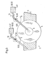
- Fig. 2 is another embodiment according to Fig. 1 shown with rotatably arranged feeds in a schematic manner.
- three different feeds 8, namely a first feed 81, a second feed 82 and a third feed 83 are provided, which are arranged on a substantially formed as a circular ring Pulverinjektorhalter 12.
- the substrate 3 can be successively coated with at least three different layers.
- this also applies, of course, to the powder injector holder 12 Fig. 1 as well.
- the coating process with the thermal spray device 1 works according to Fig. 2 completely analogous to the way in which he describes the Fig. 1 has already been explained in detail.
- the essential difference is that the change from one feed 8, for example from the first feed 81, to another feed 82 or 83 is effected by a rotational movement of the powder injector holder 12 about an axis of rotation 14, as symbolized by the double arrow 9, and not by a linear movement, as in the powder injector according to Fig. 1 ,
- FIG. 3 A third embodiment with pivotally arranged feeds is in Fig. 3 shown.
- This spray device 1 is also suitable for successively coating the substrate 3 with two different spray powders 41, 42.
- the essential difference from the embodiment according to Fig. 1 consists merely in that the change of the feeds 81, 82 occurs in that the feeders 81, 82, preferably simultaneously, are pivotable about a respective rotation axis 14, as indicated by the double arrows 9 symbolically.
- the supply 81 is pivoted away from the region of the heating zone 6 as shown to the left about the axis 141, and the feeder 82nd pivoted about the axis 142 in the region of the heating zone 6. Accordingly, as in the above already described exactly two other embodiments, the valves 13, which regulate the supply of the spray powders 41, 42, opened or closed.
- a spray device 1 with movably arranged spray guns 5, 51, 52 is shown.
- This particular embodiment is particularly suitable when, for example, two layers with two different spray guns are to be applied with one and the same spray powder. It is well known that with different spray guns that operate with different spray parameters or by different methods, layers with different properties can be sprayed with one and the same spray powder. So can the in Fig. 4 schematically shown spray gun 51, for example, a Sulzer Metco F4-MB plasma spray gun, while the spray gun 52 is a Sulzer Metco Triplex II plasma spray gun.
- the two spray guns 51, 52 may also be two spray guns 5 operating on different principles.
- the spray gun 51 may be a flame spray gun 51 while the spray gun 52 is a plasma spray gun 52 or a wire spray gun 52.
- any other combination of types of spray guns 5 is possible.
- a substrate to be coated 3 positioned in front of a feed 8, wherein during a spraying operation, a first spray gun 51 is exchangeable with a second spray gun 52.
- the two spray guns 51, 52 are mounted on a movable spray gun holder 15, which is used to change the spray guns 51, 52 is displaceable in the direction of the double arrow 9 during the injection process, so that one layer with the spray gun 51 and then a second layer can be sprayed with the spray gun 52 successively first.
- the spray guns 51, 52 may also be mounted on an annular spray gun holder 15, or that the spray guns 51, 52 may also be arranged pivotably.
- more than two identical or different spray guns 5 can be provided on a spray gun holder 15 in order to be able to spray more than two different layers onto a substrate 3.
- thermal spray devices 1 in which a plurality of identical or different types of spray guns 5 are provided, and one or more different feeds 8, which are exactly like the spray guns 5 separately or together against each other movable, so that sprayed layer systems can be made of different spray powders and / or according to different spraying methods, such as Plasma spraying, wire spraying, HVOF etc. can be sprayed.
Landscapes
- Chemical & Material Sciences (AREA)
- Engineering & Computer Science (AREA)
- Physics & Mathematics (AREA)
- Plasma & Fusion (AREA)
- Chemical Kinetics & Catalysis (AREA)
- Materials Engineering (AREA)
- Mechanical Engineering (AREA)
- Metallurgy (AREA)
- Organic Chemistry (AREA)
- Coating By Spraying Or Casting (AREA)
- Nozzles (AREA)
Claims (12)
- Dispositif de pulvérisation thermique pour le revêtement d'une surface (2) d'un substrat (3) par un matériau de revêtement (4) lors d'un processus de pulvérisation thermique, comprenant un pistolet de pulvérisation (5) avec une installation de chauffage pour chauffer le matériau de revêtement (4) dans une zone de chauffage (6) ainsi qu'une installation de chargement avec une amenée (8) par laquelle le matériau de revêtement (4) peut être introduit dans la zone de chauffage (6), où le dispositif de pulvérisation thermique est réalisé de façon qu'une position relative (9) entre l'amenée (8) et la zone de chauffage (6) est modifiable à l'état de fonctionnement, caractérisé en ce qu'au moins une première amenée (81) et une deuxième amenée (82) sont prévues, et que la première amenée (81) et/ou la deuxième amenée (82) est disposée d'une manière mobile relativement à la zone de chauffage (6) de telle sorte à l'extérieur du pistolet de pulvérisation que la première et/ou deuxième amenée soit éloignée totalement de la zone de chauffage lorsque la deuxième et/ou première amenée se trouve dans l'étendue de la zone de chauffage de sorte qu'une première couche de pulvérisation thermique peut être appliquée avec une première poudre de pulvérisation et une deuxième couche de pulvérisation thermique avec une deuxième poudre de pulvérisation successivement sans interruption du processus de pulvérisation thermique sur le substrat (3) sans que la deuxième couche de pulvérisation thermique soit contaminée par la première poudre de pulvérisation et/ou sans que la première couche de pulvérisation thermique soit contaminée par la deuxième poudre de pulvérisation.
- Dispositif de pulvérisation thermique selon la revendication 1, dans lequel l'installation de chauffage est un brûleur de plasma et/ou une installation de chauffage pour la projection de métaux fondus et/ou une installation de chauffage pour la projection à l'arc et/ou une installation de chauffage pour la projection à choc à la flamme et/ou une autre source de chaleur thermique.
- Dispositif de pulvérisation thermique selon la revendication 1 ou 2, dans lequel le matériau de revêtement (4) se présente sous forme de poudre de pulvérisation (4) et/ou de fil de pulvérisation (4).
- Dispositif de pulvérisation thermique selon l'une des revendications précédentes, dans lequel l'amenée (8) est disposée d'une manière mobile relativement à la zone de chauffage (6).
- Dispositif de pulvérisation thermique selon l'une des revendications précédentes, dans lequel par la première amenée (81), un premier matériau de revêtement (41) peut être amené, et par la deuxième amenée (82) un deuxième matériau de revêtement (42) peut être amené.
- Dispositif de pulvérisation thermique selon l'une des revendications précédentes, dans lequel le dispositif de projection est configuré de façon que la zone de chauffage (6) soit disposée d'une manière mobile relativement à l'amenée (8, 81, 82).
- Dispositif de pulvérisation thermique selon l'une des revendications précédentes, dans lequel au moins une première installation de chauffage pour produire une première zone de chauffage (61) et une deuxième installation de chauffage pour produire une deuxième zone de chauffage (62) sont prévues, et le dispositif de pulvérisation est configuré de façon qu'au moins la première zone de chauffage (61) soit disposée d'une manière mobile relativement à l'amenée (8, 81, 82).
- Dispositif de pulvérisation thermique selon l'une des revendications précédentes, dans lequel est prévue une unité de nettoyage.
- Dispositif de pulvérisation thermique selon l'une des revendications précédentes, dans lequel l'amenée (8, 81, 82) et/ou la zone de chauffage (6, 61, 62) et/ou l'unité de nettoyage sont disposées linéairement les unes contre les autres au moyen d'un entraînement.
- Dispositif de pulvérisation thermique selon l'une des revendications précédentes, dans lequel l'amenée (8, 81, 82) et/ou la zone de chauffage (6, 61, 62) et/ou l'unité de nettoyage sont disposées d'une manière tournante les unes contre les autres au moyen d'un entraînement.
- Dispositif de pulvérisation thermique selon l'une des revendications précédentes, dans lequel l'entraînement est un entraînement pneumatique et/ou un entraînement hydraulique et/ou un entraînement magnétique et/ou un entraînement électrique, en particulier un moteur linéaire ou une machine de rotation.
- Procédé de pulvérisation thermique, dans lequel une surface (2) d'un substrat (3) est revêtue lors d'un processus de pulvérisation thermique d'un matériau de revêtement (4) au moyen d'un dispositif de pulvérisation thermique (1), comprenant un pistolet de pulvérisation (5) avec une installation de chauffage, et comprenant en outre une installation de chargement avec une amenée (8), où le matériau de revêtement (4) est introduit par l'amenée (8) dans la zone de chauffage (6) et est chauffé dans la zone de chauffage (6) par l'installation de chauffage, et une position relative (9) entre l'amenée (8) et la zone de chauffage (6) est modifiée à l'état de fonctionnement, caractérisé en ce qu'au moins une première amenée (81) et une deuxième amenée (82) sont prévues à l'extérieur du pistolet de pulvérisation, et que la première amenée (81) et/ou la deuxième amenée (82) est déplacée relativement à la zone de chauffage (6) de façon que la première et/ou deuxième amenée soit éloignée totalement de la zone de chauffage lorsque la deuxième et/ou première amenée se trouve dans l'étendue de la zone de chauffage de sorte qu'une première couche de pulvérisation thermique est appliquée avec une première poudre de pulvérisation et une deuxième couche de pulvérisation thermique avec une deuxième poudre de pulvérisation successivement sans interruption du processus de pulvérisation thermique sur le substrat (3) sans que la deuxième couche de pulvérisation thermique soit contaminée par la première poudre de pulvérisation et/ou sans que la première couche de pulvérisation thermique soit contaminée par la deuxième poudre de pulvérisation.
Priority Applications (1)
| Application Number | Priority Date | Filing Date | Title |
|---|---|---|---|
| EP05405569A EP1652956B1 (fr) | 2004-11-02 | 2005-10-04 | Dispositif et procédé de pulvérisation thermique |
Applications Claiming Priority (2)
| Application Number | Priority Date | Filing Date | Title |
|---|---|---|---|
| EP04405667 | 2004-11-02 | ||
| EP05405569A EP1652956B1 (fr) | 2004-11-02 | 2005-10-04 | Dispositif et procédé de pulvérisation thermique |
Publications (2)
| Publication Number | Publication Date |
|---|---|
| EP1652956A1 EP1652956A1 (fr) | 2006-05-03 |
| EP1652956B1 true EP1652956B1 (fr) | 2011-01-12 |
Family
ID=36123792
Family Applications (1)
| Application Number | Title | Priority Date | Filing Date |
|---|---|---|---|
| EP05405569A Expired - Lifetime EP1652956B1 (fr) | 2004-11-02 | 2005-10-04 | Dispositif et procédé de pulvérisation thermique |
Country Status (1)
| Country | Link |
|---|---|
| EP (1) | EP1652956B1 (fr) |
Families Citing this family (2)
| Publication number | Priority date | Publication date | Assignee | Title |
|---|---|---|---|---|
| EP2366730B1 (fr) * | 2010-03-17 | 2016-03-16 | Innovent e.V. | Procédé de modification chimique de la surface polymère d'une matière solide particulaire |
| CN101921993B (zh) * | 2010-09-02 | 2011-09-28 | 上海交通大学 | 聚合物薄膜纳米掺杂扬尘装置及其掺杂方法 |
Family Cites Families (5)
| Publication number | Priority date | Publication date | Assignee | Title |
|---|---|---|---|---|
| JPH05179417A (ja) * | 1991-12-27 | 1993-07-20 | Nippon Steel Corp | プラズマ溶射装置 |
| JPH09263927A (ja) * | 1996-03-28 | 1997-10-07 | Toyota Motor Corp | 傾斜組成皮膜の形成方法 |
| JPH1068059A (ja) * | 1996-08-28 | 1998-03-10 | Aisin Seiki Co Ltd | 爆発溶射方法 |
| JPH10152766A (ja) * | 1996-11-26 | 1998-06-09 | Mitsubishi Heavy Ind Ltd | プラズマ溶射トーチ |
| JP3733461B2 (ja) * | 2001-01-31 | 2006-01-11 | 中国電力株式会社 | 複合トーチ型プラズマ発生方法及び装置 |
-
2005
- 2005-10-04 EP EP05405569A patent/EP1652956B1/fr not_active Expired - Lifetime
Also Published As
| Publication number | Publication date |
|---|---|
| EP1652956A1 (fr) | 2006-05-03 |
Similar Documents
| Publication | Publication Date | Title |
|---|---|---|
| DE2452684C2 (de) | Verfahren und Vorrichtung zur gleichmäßigen Verteilung eines Stromes zerstäubter Teilchen auf einem Substrat | |
| EP2455510B1 (fr) | Dispositif de revêtement thermique de surfaces intérieures de cylindres dans des carters | |
| DE69123152T2 (de) | Hochgeschwindigkeitslichtbogenspritzvorrichtung und verfahren zum formen von material | |
| WO2013083671A1 (fr) | Procédé de revêtement d'un substrat | |
| EP0915184B1 (fr) | Procédé de fabrication d'une couche de céramique sur un substrat métallique | |
| EP1980773B1 (fr) | Procédé de projection thermique destiné à recouvrir une gorge annulaire, utilisation d'un fil de projection tout comme piston doté d'un revêtement thermique | |
| DE3503105A1 (de) | Verfahren zum beschichten von maschinenteilen und werkzeugen mit hartstoffmaterial und durch das verfahren hergestellte maschinenteile und werkzeuge | |
| DD259586A5 (de) | Verfahren zur herstellung von gespruehten abreibbaren beschichtungen und nach dem verfahren hergestellte beschichtung | |
| WO2010003396A1 (fr) | Procédé et dispositif de pulvérisation gazeuse à froid | |
| EP3463678B1 (fr) | Procede de revetement | |
| EP0532134A1 (fr) | Procédé et appareil pour revêter un substrat avec un polymère résistant à la chaleur | |
| EP2427585B1 (fr) | Procédé de revêtement d'un substrat | |
| US20060090699A1 (en) | Thermal spraying apparatus and also a thermal spraying process | |
| EP1652956B1 (fr) | Dispositif et procédé de pulvérisation thermique | |
| EP2711441B1 (fr) | Dispositif et procédé destinés à la production d'un système de couches | |
| EP2014415B1 (fr) | Procédé de traitement d'une surface d'un composant d'un turbine à gas | |
| DE4226768C2 (de) | Vorrichtung zur Förderung und Aufbereitung von Kunststoffmaterial | |
| DE4016412C2 (fr) | ||
| WO2013083672A1 (fr) | Dispositif de projection plasma et procédé de revêtement | |
| EP1387896B1 (fr) | Ustensile de cuisine a revetement par projection thermique et procede de production de ce revetement | |
| DE2830316A1 (de) | Spritz- bzw. giesskopf zum beschichten von gegenstaenden | |
| EP1350862A1 (fr) | Procédé et apparail d'application thermique d'un revêtement sur une surface | |
| DE2544847A1 (de) | Thermische pulverspritzvorrichtung | |
| DE102006061652A1 (de) | Verfahren und Vorrichtung zum Beschichten eines Hohlkörpers | |
| DE102011114395A1 (de) | Vorrichtung zum thermischen Beschichten |
Legal Events
| Date | Code | Title | Description |
|---|---|---|---|
| PUAI | Public reference made under article 153(3) epc to a published international application that has entered the european phase |
Free format text: ORIGINAL CODE: 0009012 |
|
| AK | Designated contracting states |
Kind code of ref document: A1 Designated state(s): AT BE BG CH CY CZ DE DK EE ES FI FR GB GR HU IE IS IT LI LT LU LV MC NL PL PT RO SE SI SK TR |
|
| AX | Request for extension of the european patent |
Extension state: AL BA HR MK YU |
|
| 17P | Request for examination filed |
Effective date: 20061005 |
|
| AKX | Designation fees paid |
Designated state(s): AT BE BG CH CY CZ DE DK EE ES FI FR GB GR HU IE IS IT LI LT LU LV MC NL PL PT RO SE SI SK TR |
|
| 17Q | First examination report despatched |
Effective date: 20070416 |
|
| GRAP | Despatch of communication of intention to grant a patent |
Free format text: ORIGINAL CODE: EPIDOSNIGR1 |
|
| GRAS | Grant fee paid |
Free format text: ORIGINAL CODE: EPIDOSNIGR3 |
|
| GRAA | (expected) grant |
Free format text: ORIGINAL CODE: 0009210 |
|
| AK | Designated contracting states |
Kind code of ref document: B1 Designated state(s): AT BE BG CH CY CZ DE DK EE ES FI FR GB GR HU IE IS IT LI LT LU LV MC NL PL PT RO SE SI SK TR |
|
| REG | Reference to a national code |
Ref country code: GB Ref legal event code: FG4D Free format text: NOT ENGLISH |
|
| REG | Reference to a national code |
Ref country code: CH Ref legal event code: NV Representative=s name: SULZER MANAGEMENT AG PATENTABTEILUNG/0067 Ref country code: CH Ref legal event code: EP |
|
| REG | Reference to a national code |
Ref country code: IE Ref legal event code: FG4D Free format text: LANGUAGE OF EP DOCUMENT: GERMAN |
|
| REF | Corresponds to: |
Ref document number: 502005010829 Country of ref document: DE Date of ref document: 20110224 Kind code of ref document: P |
|
| REG | Reference to a national code |
Ref country code: DE Ref legal event code: R096 Ref document number: 502005010829 Country of ref document: DE Effective date: 20110224 |
|
| REG | Reference to a national code |
Ref country code: SE Ref legal event code: TRGR |
|
| REG | Reference to a national code |
Ref country code: NL Ref legal event code: T3 |
|
| LTIE | Lt: invalidation of european patent or patent extension |
Effective date: 20110112 |
|
| PG25 | Lapsed in a contracting state [announced via postgrant information from national office to epo] |
Ref country code: LV Free format text: LAPSE BECAUSE OF FAILURE TO SUBMIT A TRANSLATION OF THE DESCRIPTION OR TO PAY THE FEE WITHIN THE PRESCRIBED TIME-LIMIT Effective date: 20110112 Ref country code: ES Free format text: LAPSE BECAUSE OF FAILURE TO SUBMIT A TRANSLATION OF THE DESCRIPTION OR TO PAY THE FEE WITHIN THE PRESCRIBED TIME-LIMIT Effective date: 20110423 Ref country code: IS Free format text: LAPSE BECAUSE OF FAILURE TO SUBMIT A TRANSLATION OF THE DESCRIPTION OR TO PAY THE FEE WITHIN THE PRESCRIBED TIME-LIMIT Effective date: 20110512 Ref country code: GR Free format text: LAPSE BECAUSE OF FAILURE TO SUBMIT A TRANSLATION OF THE DESCRIPTION OR TO PAY THE FEE WITHIN THE PRESCRIBED TIME-LIMIT Effective date: 20110413 Ref country code: PT Free format text: LAPSE BECAUSE OF FAILURE TO SUBMIT A TRANSLATION OF THE DESCRIPTION OR TO PAY THE FEE WITHIN THE PRESCRIBED TIME-LIMIT Effective date: 20110512 Ref country code: LT Free format text: LAPSE BECAUSE OF FAILURE TO SUBMIT A TRANSLATION OF THE DESCRIPTION OR TO PAY THE FEE WITHIN THE PRESCRIBED TIME-LIMIT Effective date: 20110112 |
|
| REG | Reference to a national code |
Ref country code: IE Ref legal event code: FD4D |
|
| PG25 | Lapsed in a contracting state [announced via postgrant information from national office to epo] |
Ref country code: FI Free format text: LAPSE BECAUSE OF FAILURE TO SUBMIT A TRANSLATION OF THE DESCRIPTION OR TO PAY THE FEE WITHIN THE PRESCRIBED TIME-LIMIT Effective date: 20110112 Ref country code: CY Free format text: LAPSE BECAUSE OF FAILURE TO SUBMIT A TRANSLATION OF THE DESCRIPTION OR TO PAY THE FEE WITHIN THE PRESCRIBED TIME-LIMIT Effective date: 20110112 Ref country code: SI Free format text: LAPSE BECAUSE OF FAILURE TO SUBMIT A TRANSLATION OF THE DESCRIPTION OR TO PAY THE FEE WITHIN THE PRESCRIBED TIME-LIMIT Effective date: 20110112 Ref country code: BG Free format text: LAPSE BECAUSE OF FAILURE TO SUBMIT A TRANSLATION OF THE DESCRIPTION OR TO PAY THE FEE WITHIN THE PRESCRIBED TIME-LIMIT Effective date: 20110412 Ref country code: PL Free format text: LAPSE BECAUSE OF FAILURE TO SUBMIT A TRANSLATION OF THE DESCRIPTION OR TO PAY THE FEE WITHIN THE PRESCRIBED TIME-LIMIT Effective date: 20110112 |
|
| PG25 | Lapsed in a contracting state [announced via postgrant information from national office to epo] |
Ref country code: IE Free format text: LAPSE BECAUSE OF FAILURE TO SUBMIT A TRANSLATION OF THE DESCRIPTION OR TO PAY THE FEE WITHIN THE PRESCRIBED TIME-LIMIT Effective date: 20110112 Ref country code: EE Free format text: LAPSE BECAUSE OF FAILURE TO SUBMIT A TRANSLATION OF THE DESCRIPTION OR TO PAY THE FEE WITHIN THE PRESCRIBED TIME-LIMIT Effective date: 20110112 Ref country code: DK Free format text: LAPSE BECAUSE OF FAILURE TO SUBMIT A TRANSLATION OF THE DESCRIPTION OR TO PAY THE FEE WITHIN THE PRESCRIBED TIME-LIMIT Effective date: 20110112 |
|
| PLBE | No opposition filed within time limit |
Free format text: ORIGINAL CODE: 0009261 |
|
| STAA | Information on the status of an ep patent application or granted ep patent |
Free format text: STATUS: NO OPPOSITION FILED WITHIN TIME LIMIT |
|
| PG25 | Lapsed in a contracting state [announced via postgrant information from national office to epo] |
Ref country code: RO Free format text: LAPSE BECAUSE OF FAILURE TO SUBMIT A TRANSLATION OF THE DESCRIPTION OR TO PAY THE FEE WITHIN THE PRESCRIBED TIME-LIMIT Effective date: 20110112 Ref country code: SK Free format text: LAPSE BECAUSE OF FAILURE TO SUBMIT A TRANSLATION OF THE DESCRIPTION OR TO PAY THE FEE WITHIN THE PRESCRIBED TIME-LIMIT Effective date: 20110112 Ref country code: CZ Free format text: LAPSE BECAUSE OF FAILURE TO SUBMIT A TRANSLATION OF THE DESCRIPTION OR TO PAY THE FEE WITHIN THE PRESCRIBED TIME-LIMIT Effective date: 20110112 |
|
| 26N | No opposition filed |
Effective date: 20111013 |
|
| REG | Reference to a national code |
Ref country code: DE Ref legal event code: R097 Ref document number: 502005010829 Country of ref document: DE Effective date: 20111013 |
|
| PG25 | Lapsed in a contracting state [announced via postgrant information from national office to epo] |
Ref country code: MC Free format text: LAPSE BECAUSE OF NON-PAYMENT OF DUE FEES Effective date: 20111031 |
|
| PG25 | Lapsed in a contracting state [announced via postgrant information from national office to epo] |
Ref country code: LU Free format text: LAPSE BECAUSE OF NON-PAYMENT OF DUE FEES Effective date: 20111004 |
|
| PG25 | Lapsed in a contracting state [announced via postgrant information from national office to epo] |
Ref country code: TR Free format text: LAPSE BECAUSE OF FAILURE TO SUBMIT A TRANSLATION OF THE DESCRIPTION OR TO PAY THE FEE WITHIN THE PRESCRIBED TIME-LIMIT Effective date: 20110112 |
|
| PG25 | Lapsed in a contracting state [announced via postgrant information from national office to epo] |
Ref country code: HU Free format text: LAPSE BECAUSE OF FAILURE TO SUBMIT A TRANSLATION OF THE DESCRIPTION OR TO PAY THE FEE WITHIN THE PRESCRIBED TIME-LIMIT Effective date: 20110112 |
|
| PGFP | Annual fee paid to national office [announced via postgrant information from national office to epo] |
Ref country code: SE Payment date: 20131022 Year of fee payment: 9 Ref country code: FR Payment date: 20131022 Year of fee payment: 9 Ref country code: BE Payment date: 20131022 Year of fee payment: 9 Ref country code: AT Payment date: 20131011 Year of fee payment: 9 Ref country code: CH Payment date: 20131021 Year of fee payment: 9 Ref country code: GB Payment date: 20131021 Year of fee payment: 9 Ref country code: DE Payment date: 20131021 Year of fee payment: 9 |
|
| PGFP | Annual fee paid to national office [announced via postgrant information from national office to epo] |
Ref country code: IT Payment date: 20131028 Year of fee payment: 9 Ref country code: NL Payment date: 20131022 Year of fee payment: 9 |
|
| REG | Reference to a national code |
Ref country code: CH Ref legal event code: NV Representative=s name: INTELLECTUAL PROPERTY SERVICES GMBH, CH |
|
| REG | Reference to a national code |
Ref country code: DE Ref legal event code: R119 Ref document number: 502005010829 Country of ref document: DE |
|
| REG | Reference to a national code |
Ref country code: NL Ref legal event code: V1 Effective date: 20150501 |
|
| REG | Reference to a national code |
Ref country code: CH Ref legal event code: PL |
|
| REG | Reference to a national code |
Ref country code: SE Ref legal event code: EUG |
|
| REG | Reference to a national code |
Ref country code: AT Ref legal event code: MM01 Ref document number: 495278 Country of ref document: AT Kind code of ref document: T Effective date: 20141004 |
|
| GBPC | Gb: european patent ceased through non-payment of renewal fee |
Effective date: 20141004 |
|
| PG25 | Lapsed in a contracting state [announced via postgrant information from national office to epo] |
Ref country code: BE Free format text: LAPSE BECAUSE OF NON-PAYMENT OF DUE FEES Effective date: 20141031 |
|
| PG25 | Lapsed in a contracting state [announced via postgrant information from national office to epo] |
Ref country code: CH Free format text: LAPSE BECAUSE OF NON-PAYMENT OF DUE FEES Effective date: 20141031 Ref country code: GB Free format text: LAPSE BECAUSE OF NON-PAYMENT OF DUE FEES Effective date: 20141004 Ref country code: LI Free format text: LAPSE BECAUSE OF NON-PAYMENT OF DUE FEES Effective date: 20141031 Ref country code: DE Free format text: LAPSE BECAUSE OF NON-PAYMENT OF DUE FEES Effective date: 20150501 Ref country code: SE Free format text: LAPSE BECAUSE OF NON-PAYMENT OF DUE FEES Effective date: 20141005 |
|
| REG | Reference to a national code |
Ref country code: FR Ref legal event code: ST Effective date: 20150630 |
|
| PG25 | Lapsed in a contracting state [announced via postgrant information from national office to epo] |
Ref country code: FR Free format text: LAPSE BECAUSE OF NON-PAYMENT OF DUE FEES Effective date: 20141031 Ref country code: AT Free format text: LAPSE BECAUSE OF NON-PAYMENT OF DUE FEES Effective date: 20141004 Ref country code: IT Free format text: LAPSE BECAUSE OF NON-PAYMENT OF DUE FEES Effective date: 20141004 Ref country code: NL Free format text: LAPSE BECAUSE OF NON-PAYMENT OF DUE FEES Effective date: 20150501 |