EP1656304B1 - Tete de distribution de produit fluide - Google Patents
Tete de distribution de produit fluide Download PDFInfo
- Publication number
- EP1656304B1 EP1656304B1 EP04767674A EP04767674A EP1656304B1 EP 1656304 B1 EP1656304 B1 EP 1656304B1 EP 04767674 A EP04767674 A EP 04767674A EP 04767674 A EP04767674 A EP 04767674A EP 1656304 B1 EP1656304 B1 EP 1656304B1
- Authority
- EP
- European Patent Office
- Prior art keywords
- base
- dispenser
- orifice
- axial
- head according
- Prior art date
- Legal status (The legal status is an assumption and is not a legal conclusion. Google has not performed a legal analysis and makes no representation as to the accuracy of the status listed.)
- Expired - Lifetime
Links
- 239000012530 fluid Substances 0.000 title claims description 20
- 238000006073 displacement reaction Methods 0.000 claims description 7
- 230000000694 effects Effects 0.000 description 5
- 239000000470 constituent Substances 0.000 description 4
- 238000007790 scraping Methods 0.000 description 4
- 238000007789 sealing Methods 0.000 description 4
- 239000007788 liquid Substances 0.000 description 2
- 150000003839 salts Chemical class 0.000 description 2
- 235000002566 Capsicum Nutrition 0.000 description 1
- 239000006002 Pepper Substances 0.000 description 1
- 235000016761 Piper aduncum Nutrition 0.000 description 1
- 235000017804 Piper guineense Nutrition 0.000 description 1
- 244000203593 Piper nigrum Species 0.000 description 1
- 235000008184 Piper nigrum Nutrition 0.000 description 1
- 239000002537 cosmetic Substances 0.000 description 1
- 239000006071 cream Substances 0.000 description 1
- 230000000994 depressogenic effect Effects 0.000 description 1
- 235000013305 food Nutrition 0.000 description 1
- 238000000465 moulding Methods 0.000 description 1
- 238000004806 packaging method and process Methods 0.000 description 1
- 239000000843 powder Substances 0.000 description 1
- 239000002453 shampoo Substances 0.000 description 1
- 230000003068 static effect Effects 0.000 description 1
Images


Classifications
-
- B—PERFORMING OPERATIONS; TRANSPORTING
- B65—CONVEYING; PACKING; STORING; HANDLING THIN OR FILAMENTARY MATERIAL
- B65D—CONTAINERS FOR STORAGE OR TRANSPORT OF ARTICLES OR MATERIALS, e.g. BAGS, BARRELS, BOTTLES, BOXES, CANS, CARTONS, CRATES, DRUMS, JARS, TANKS, HOPPERS, FORWARDING CONTAINERS; ACCESSORIES, CLOSURES, OR FITTINGS THEREFOR; PACKAGING ELEMENTS; PACKAGES
- B65D47/00—Closures with filling and discharging, or with discharging, devices
- B65D47/04—Closures with discharging devices other than pumps
- B65D47/20—Closures with discharging devices other than pumps comprising hand-operated members for controlling discharge
- B65D47/24—Closures with discharging devices other than pumps comprising hand-operated members for controlling discharge with poppet valves or lift valves, i.e. valves opening or closing a passageway by a relative motion substantially perpendicular to the plane of the seat
- B65D47/241—Closures with discharging devices other than pumps comprising hand-operated members for controlling discharge with poppet valves or lift valves, i.e. valves opening or closing a passageway by a relative motion substantially perpendicular to the plane of the seat the valve being opened or closed by actuating a cap-like element
- B65D47/242—Closures with discharging devices other than pumps comprising hand-operated members for controlling discharge with poppet valves or lift valves, i.e. valves opening or closing a passageway by a relative motion substantially perpendicular to the plane of the seat the valve being opened or closed by actuating a cap-like element moving helically
Definitions
- the present invention relates to a fluid dispenser head intended to be associated with a fluid reservoir.
- This dispensing head generally comprises a fixed base formed by or mounted on the tank.
- the head includes a rotary actuator rotatably mounted on the base about an axis between two end stop positions.
- the head comprises a dispensing orifice selectively closable by rotation of the actuating element on the base.
- This type of dispensing head is frequently used as an actuatable closure system for the dispensing of liquid, granular or powder fluid product stored in a reservoir.
- a preferred application of this kind of head exists in the fields of the food industry, body care or cosmetics. Other fields are not excluded, however.
- a dispensing head according to the preamble of claim 1 is known from US-A-5000360.
- this type of manifold distribution head and rotary actuating element is operable between an open position and a closed position by rotating the actuating element on the base. It is also known that the rotation of the rotary element on the base makes it possible to unmask or disengage one or more orifice (s) of closed distribution (s) in the closed position. Heads provided with several dispensing orifices of different cross sections are also known so that the flow rate of the fluid product can be varied through the dispensing orifices.
- the present invention relates to a type of dispensing head with a single dispensing orifice. The orifice may, however, comprise several holes. With this type of dispensing head with a single dispensing orifice, the rotary displacement of the actuating element only makes it possible to close or disengage the dispensing orifice between the two extreme stop positions.
- the present invention aims to define a dispensing head with a single dispensing orifice which allows modular use of the dispensing orifice. Another object of the invention is to allow a graduated clearance of the dispensing orifice.
- the present invention proposes a dispensing head according to claim 1.
- the two extreme stop positions during the rotation of the actuating element on the base, define two opening positions of the dispensing orifice separated by at least one intermediate position of closure of the dispensing orifice.
- the dispensing head comprises flow variation means making it possible to vary the flow rate of the fluid product through the dispensing orifice from one open position to the other. Therefore, an open position allows more fluid to be dispensed than the other open position for a given time. This gives a modular distribution of fluid product through a single dispensing orifice.
- the dispensing orifice is located on the axis of rotation of the element on the base.
- the packaging or dispenser equipped with the dispensing head according to the invention is then in the form of a salt shaker or a conventional pepper with a single axial central distribution orifice.
- the dispensing head comprises axial displacement means able to move the element axially relative to the base during its rotation on the base.
- the axial displacement means comprise at least one guide path having two different sections connected together at a low point, the two sections each defining a respective end stop, the two end stops respectively corresponding to the two open positions and the low point corresponding to the closed position.
- the base forms at least one guide window axial rotator which extends over a periphery portion of the base, said window defining a guide path, said window forming two window sections connected together, a first section defining a first slope and the second section defining a second different slope of the first slope, each section defining a stop end, the abutment ends being axially offset, the actuating element comprising at least one axial rotational guide pin engaged in said window so that a rotation of the element actuation on the base has the effect of moving said at least one lug in its respective window, thus moving the actuating element axially to reach different heights depending on whether the lug is in abutment on the first or the second section.
- the base comprises a ring formed with several axial rotary guide windows distributed over the periphery of the ring, the cap comprising a skirt which extends around the ring and which internally forms a plurality of guide pins. axial rotary engaged in respective windows.
- the element forms the dispensing orifice and the base forms a shutter needle engaged in the closed position in the dispensing orifice, and disengaged from the orifice in the positions of opening differently so that the flow rates through the orifice are different in the two open positions. It is the more or less pronounced disengagement of the valve from the dispensing opening which makes it possible to vary the flow from one opening position to the other. More precisely, this more or less pronounced disengagement makes it possible to vary the passage section of the fluid product just downstream of the single dispensing orifice.
- the actuating element comprises axial guiding means engaged around the needle so that the needle is slidably mounted in said axial guiding means, said guiding means extending downwards from the periphery of the lug. distribution orifice, said guide means forming a plurality of lights of variable sizes in depending on the position of the needle in the axial guide means.
- the axial guide means comprise a plurality of tabs which extend downwards from the outer periphery of the dispensing orifice, said tabs being connected by a scraping ring slidably engaged around the needle. .
- the base may comprise an internal sleeve inside which the needle extends, the actuating element comprising a cover disposed on the sleeve and forming the dispensing orifice, said cap comprising an annular lip in sliding contact. rotary seal in said sleeve.
- the actuating element comprises a detachable guarantee tongue blocked by the base so that the actuating element is locked in rotation on the base in the closed position.
- the fluid dispenser equipped with the dispensing head according to the invention comprises a reservoir 1 for containing fluid, for example salt, a cream or a shampoo. More generally, the fluid product may be liquid, granular or powdery.
- the tank 1 forms at its upper end a snap groove 11, a shoulder 12 which extends radially inwards and which terminates in a neck 13.
- the neck 13 defines an opening allowing the fluid product stored in the reservoir to be extracted.
- the reservoir is not a critical component for the present invention: it can be of any shape and size. Even the snap groove 11 and the shoulder 12 and the neck 13 may have a different configuration without departing from the scope of the present invention.
- This reservoir 1 is here associated with a dispensing head comprising two constituent elements, namely a base 2 and a rotary actuating element 3.
- the base 2 is here mounted on the reservoir 1, but it is also possible to envisage that the base 2 is made integrally with the reservoir 1.
- the dispensing head here comprises only two constituent elements, it is not excluded that it may further comprise other constituent elements in certain embodiments that do not come out. not the scope of the invention. An example with two constituent elements is, however, advantageous from the point of view of molding and assembly.
- the base 2 comprises an inner sleeve 21 defining a lower end portion 211 in sealing contact in the neck 13. This is a static sealing contact, since the base 2 is intended to be fixedly mounted on the reservoir 1.
- the sleeve 21 defines an internal passage which is in direct communication with the interior of the reservoir 1, since the sleeve is disposed inside the neck 13.
- a needle 20 defining an outer upper end 201 is centrally and axially disposed inside the sleeve 21.
- Holding flanges 202 connect the inner wall of the sleeve 21 to the needle 20.
- needle 20 preferably has a cylindrical outer wall from its upper end 201.
- the sleeve 21 is connected at its upper end to a ring 22 which extends coaxially around the sleeve 21.
- the ring 22 is provided with a plurality of windows 221 which provide openings in the wall of the ring 22. These windows 221, which here are three in number, form a guide path. The windows are equiangularly distributed around the periphery of the crown 22.
- Each window 221 is substantially in the form of a chevron with the point directed downwards.
- each window 221 defines a first window section 2211 and a second window section 2212. Each section is in the form of a substantially rectilinear slit or ramp, but inclined with respect to the horizontal or the vertical.
- each section has a slope 2215, 2216 having a certain length, a certain profile and a certain degree of inclination.
- the degrees of inclination of the two slopes may be identical, but preferably, according to the invention the degrees of inclination of these two slopes are different.
- the first section 2211 has a slope inclination degree lower than the second window section 2212.
- each window section 2211 and 2212 are connected together at a low point 2210.
- each window section includes a stop end 2213, 2214 which defines the extreme extent of the window sections. These abutment ends 2213 and 2214 are here equidistant from the low point 2210, so that each section of windows has an identical length.
- the abutment ends 2213 and 2214 are not located in the same plane, but instead axially offset. Since the slope inclination degree of the second section 2212 is greater than that of the first section 2211, the abutment end 2214 is located axially higher than the abutment end 2213. This axial offset of the ends the stop of the two sections of windows can also be obtained with identical inclination degrees of slopes, but with lengths of slopes of sections different windows.
- the abutment end 2214 would also be axially offset upwards with respect to the abutment end 2213
- the axial offset of the stop ends of the windows 221 can be achieved by varying either the slope degree of the window section slopes or the slope lengths of the window sections. It is also possible to envisage a combination of different lengths and degrees of inclination. However, it is not excluded according to the invention that the stop ends of the windows are arranged in the same plane. However, the offset of these ends is preferred.
- slopes 2215 and 2216 each form a recess 2217 and 2218 which breaks the linearity of the slope.
- These recesses, notches or bearings define intermediate positions between the low point 2210 and the abutment ends 2213 and 2214.
- the base 1 forms around the ring 22 a complex configuration that is not regular around the perimeter of the crown.
- the base forms two buttresses 24 interrupted on the one hand by a lower slot 25 and on the other by a range 26.
- the slot 25 is located below the buttresses 24 and the beach 26 is also located. 25 against the buttresses 25, at a height even lower than that of the slot 25.
- the slot 25 is located substantially diametrically opposite the range 26.
- the slot 25 extends over an angle of about 10 to 30 °, while the range 26 extends over an angular distance of more than 90 °.
- the base also forms at its lower outer periphery a snap-fastening collar 23 intended to cooperate with the detent groove 11 formed by the reservoir 1.
- the base 2 is fixedly mounted on the reservoir 1 at the of the groove 11, and this sealingly through the sealed engagement of the lower end portion 211 of the sleeve 21 in the neck 13.
- the rotary actuating element 3 is here in the form of a cover comprising a rotary shutter plate 31 pierced centrally with a dispensing orifice 30.
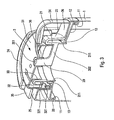
- the needle 20 is engaged substantially sealingly in the dispensing orifice 30 in FIGS. 1, 2 and 3.
- the plate 31 forms on the lower periphery of the dispensing orifice 30 an axial guide tumbler 36 which extends around the needle 20 over a certain height.
- This turret 36 is constituted by a plurality of tabs connecting the periphery of the dispensing orifice 30 to a scraper ring 362.
- the turret thus defines a plurality of passage apertures 363 between each tab 361. This is visible in FIG.
- these lights 363 form a communication passage between the internal space formed by the sleeve 21 in communication direct with the tank and the outside of the head.
- the fluid product stored in the tank 1 can flow through the dispensing orifice 30 through the passage lumens 363, when the needle 20 is withdrawn inside the head.
- the guiding and scraping turret 36 not only keeps the needle 20 in the axis of rotation of the head, but also makes it possible to clean the needle 20 with each rotation of the actuating element by a scraping effect obtained. by moving the needle in the turret.
- the ring 362 and the tabs 361 participate in this scraping action.
- the plate 31 is extended at its outer periphery by a skirt 32 which extends downwards.
- This skirt 32 is arranged concentrically around the ring 22.
- the skirt 32 here forms three lugs 221 which are engaged in respective windows 221 formed by the ring 22. This is visible in Figure 1, for a lug and a window .
- the skirt 32 comprises three lugs 321 distributed equiangularly at 120 ° on the periphery of the inner wall of the skirt 32. Since each lug 321 is engaged in a respective window 221, and this window presents a profile with two identical or different slopes, a rotation of the rotary actuating element 3 on the base 2 has the effect of moving the lugs in the windows following the profile of the slopes.
- the rotary actuating element 3 When the pins 321 are located at the 2210 of the windows 221, the rotary actuating element 3 is at its lowest level relative to the base 2. The needle 20 is then located at its highest level in the guide and scraper turret. 36. This corresponds to the closed position of the dispensing head shown in Figures 1, 2 and 3, wherein the upper end 201 of the needle 20 is located in the dispensing orifice 30 advantageously sealed. It can also be noted that the upper end 201 is located substantially in the same plane as the plate 31.
- Another opening position can of course be reached when the lugs abut against the other end stops of the windows.
- the abutment ends 2213 and 2214 are located in the same horizontal plane, that is to say when there is no axial offset between these abutment ends, the needle is depressed or disengaged in the same way with the same magnitude in the two open positions.
- the ends of abutment 2213 and 2214 are axially offset as in the preferred embodiment of the invention, the two open positions correspond to two different engagement or depression positions of the needle 20 relative to the dispensing orifice 30.
- the recesses 2217 and 2218 formed by the slopes 2215 and 2216 define stable opening intermediate positions corresponding to a fixed intermediate flow rate.
- two extreme open positions separated by a plurality of fixed intermediate opening positions and at least one fixed intermediate closing position it is possible to define two extreme open positions separated by a plurality of fixed intermediate opening positions and at least one fixed intermediate closing position. Indeed, one can provide several closing positions and more than two intermediate opening positions, or on the contrary only one intermediate opening position on one of the two slopes.
- the more or less marked or pronounced depression of the needle 20 in the turret 36, respectively in the dispensing orifice 30, makes it possible to vary the flow rate of fluid.
- the engagement of the lugs in the windows is axial displacement means while ensuring a rotation guide.
- the rotary actuating element 3 forms a sealing lip 33 in rotary sealing contact in the sleeve 21. This ensures a perfect dynamic seal of the dispensing head.
- the actuating element 3 also forms an actuating button 34 which aids in the rotational manipulation of the element 3. This actuating button 34 is situated at the level of the range 26 between the two buttresses 24. When the button 34 is in abutment against the rear buttress, when looking at Figure 4, the dispensing head is in a low flow opening position. On the other hand, when the actuating button 34 is in abutment against the other buttress 24 normally located in the foreground in FIG. 5, the dispensing head is in the open position at a high speed.
- the rotary actuating element also comprises first-use guarantee means in the form of a tongue 35 made integrally with the remainder of the actuating element 3 and disposed at the level of the
- the tongue 35 preferably extends over the entire width of the crenel 25 so as to abut with the two adjacent buttresses 24. In this way, the rotary actuating element 3 is locked in rotation in the closed position. This is clearly visible in FIG. 2, as well as in FIG. 3. To actuate the dispensing head, the tongue 35 must first be torn off.
- the displacement means in the form of the cooperation between lugs and chevron-shaped windows can be likened to a kind of chevron-shaped threading with identical or different inclination slopes and with identical slope lengths. or different.
Landscapes
- Engineering & Computer Science (AREA)
- Mechanical Engineering (AREA)
- Closures For Containers (AREA)
- Containers And Packaging Bodies Having A Special Means To Remove Contents (AREA)
- Devices For Dispensing Beverages (AREA)
- Coating Apparatus (AREA)
- Feeding, Discharge, Calcimining, Fusing, And Gas-Generation Devices (AREA)
Applications Claiming Priority (2)
| Application Number | Priority Date | Filing Date | Title |
|---|---|---|---|
| FR0308626A FR2857653B1 (fr) | 2003-07-15 | 2003-07-15 | Tete de distribution de produit fluide |
| PCT/FR2004/001845 WO2005007534A2 (fr) | 2003-07-15 | 2004-07-13 | Tête de distribution de produit fluide |
Publications (2)
| Publication Number | Publication Date |
|---|---|
| EP1656304A2 EP1656304A2 (fr) | 2006-05-17 |
| EP1656304B1 true EP1656304B1 (fr) | 2007-02-14 |
Family
ID=33548147
Family Applications (1)
| Application Number | Title | Priority Date | Filing Date |
|---|---|---|---|
| EP04767674A Expired - Lifetime EP1656304B1 (fr) | 2003-07-15 | 2004-07-13 | Tete de distribution de produit fluide |
Country Status (14)
| Country | Link |
|---|---|
| US (1) | US7748580B2 (cs) |
| EP (1) | EP1656304B1 (cs) |
| JP (1) | JP2007516135A (cs) |
| CN (1) | CN100488849C (cs) |
| AU (1) | AU2004256950B2 (cs) |
| BR (1) | BRPI0412294A (cs) |
| CA (1) | CA2532900A1 (cs) |
| CZ (1) | CZ200621A3 (cs) |
| DE (1) | DE602004004795T2 (cs) |
| ES (1) | ES2281006T3 (cs) |
| FR (1) | FR2857653B1 (cs) |
| PL (1) | PL202697B1 (cs) |
| RU (1) | RU2352507C2 (cs) |
| WO (1) | WO2005007534A2 (cs) |
Families Citing this family (5)
| Publication number | Priority date | Publication date | Assignee | Title |
|---|---|---|---|---|
| ES2254038B1 (es) * | 2005-12-22 | 2007-02-16 | Comercial Valira S.A. | Tapon con brocal automatico. |
| AT507950B1 (de) | 2009-02-23 | 2011-07-15 | Xolution Gmbh | Deckel eines behälters |
| US8141793B2 (en) * | 2009-07-14 | 2012-03-27 | The Dial Corporation | Gel air freshener and method of unsealing such gel air freshener |
| FR2978737B1 (fr) * | 2011-08-01 | 2013-08-30 | Maitrise & Innovation | Bouchon anti-goutte a capuchon mobile automatique et a haute etancheite |
| CN110271766B (zh) * | 2019-04-30 | 2020-07-21 | 嘉兴市龙骏信息科技有限公司 | 一种液体胶水盛装瓶 |
Family Cites Families (13)
| Publication number | Priority date | Publication date | Assignee | Title |
|---|---|---|---|---|
| US2533915A (en) * | 1945-05-07 | 1950-12-12 | Chester A Brooks | Rotatable closure structure having yieldable locking means |
| US3231155A (en) * | 1964-03-23 | 1966-01-25 | Paul H Mcconnell | Container and closure cap therefor |
| FR1520693A (fr) * | 1967-03-01 | 1968-04-12 | Oreal | Nouveau dispositif de bouchage pour flacons ou récipients analogues |
| US4424918A (en) * | 1981-10-16 | 1984-01-10 | Gene Stull | Non-resealable dispenser cap construction |
| BE905791A (fr) * | 1986-11-19 | 1987-03-16 | Lynes Holding Sa | Bouchon verseur. |
| US4842169A (en) * | 1987-02-03 | 1989-06-27 | Gene Stull | Twist cap having adjustable flow rate |
| US4823994A (en) * | 1987-02-25 | 1989-04-25 | Laauwe Robert H | Speciality closures for bottle necks |
| US5000360A (en) * | 1989-09-27 | 1991-03-19 | John Lown | Pouring spout which can be selectively opened and closed |
| US5429282A (en) * | 1994-03-31 | 1995-07-04 | Erie Plastics | Multi-position self-guiding closure for a container |
| FR2760724B1 (fr) * | 1997-03-14 | 1999-04-30 | Oreal | Recipient de type a capsule montee par claquage |
| US6135318A (en) * | 1997-10-08 | 2000-10-24 | Stull Technologies | Variable rate closure for dispensers having fluid contents |
| US6675995B2 (en) * | 2000-06-05 | 2004-01-13 | Stull Technologies, Inc. | Traversing twist cap |
| RU28864U1 (ru) * | 2002-10-29 | 2003-04-20 | Каневец Алексей Валерьевич | Затвор к бутылкам |
-
2003
- 2003-07-15 FR FR0308626A patent/FR2857653B1/fr not_active Expired - Fee Related
-
2004
- 2004-07-13 AU AU2004256950A patent/AU2004256950B2/en not_active Expired - Fee Related
- 2004-07-13 RU RU2006104626/12A patent/RU2352507C2/ru not_active IP Right Cessation
- 2004-07-13 US US10/564,163 patent/US7748580B2/en not_active Expired - Fee Related
- 2004-07-13 ES ES04767674T patent/ES2281006T3/es not_active Expired - Lifetime
- 2004-07-13 CA CA002532900A patent/CA2532900A1/en not_active Abandoned
- 2004-07-13 EP EP04767674A patent/EP1656304B1/fr not_active Expired - Lifetime
- 2004-07-13 CN CNB2004800234920A patent/CN100488849C/zh not_active Expired - Fee Related
- 2004-07-13 WO PCT/FR2004/001845 patent/WO2005007534A2/fr not_active Ceased
- 2004-07-13 JP JP2006519959A patent/JP2007516135A/ja active Pending
- 2004-07-13 PL PL379289A patent/PL202697B1/pl not_active IP Right Cessation
- 2004-07-13 DE DE602004004795T patent/DE602004004795T2/de not_active Expired - Lifetime
- 2004-07-13 CZ CZ20060021A patent/CZ200621A3/cs unknown
- 2004-07-13 BR BRPI0412294-1A patent/BRPI0412294A/pt not_active IP Right Cessation
Also Published As
| Publication number | Publication date |
|---|---|
| JP2007516135A (ja) | 2007-06-21 |
| WO2005007534A3 (fr) | 2005-04-14 |
| EP1656304A2 (fr) | 2006-05-17 |
| WO2005007534A2 (fr) | 2005-01-27 |
| AU2004256950A1 (en) | 2005-01-27 |
| AU2004256950B2 (en) | 2010-06-17 |
| CN100488849C (zh) | 2009-05-20 |
| CZ200621A3 (cs) | 2007-01-31 |
| ES2281006T3 (es) | 2007-09-16 |
| BRPI0412294A (pt) | 2006-09-19 |
| CA2532900A1 (en) | 2005-01-27 |
| FR2857653B1 (fr) | 2008-03-28 |
| DE602004004795T2 (de) | 2007-11-22 |
| FR2857653A1 (fr) | 2005-01-21 |
| CN1849247A (zh) | 2006-10-18 |
| US7748580B2 (en) | 2010-07-06 |
| PL202697B1 (pl) | 2009-07-31 |
| DE602004004795D1 (de) | 2007-03-29 |
| US20070017937A1 (en) | 2007-01-25 |
| RU2352507C2 (ru) | 2009-04-20 |
| RU2006104626A (ru) | 2007-08-20 |
| PL379289A1 (pl) | 2006-08-21 |
Similar Documents
| Publication | Publication Date | Title |
|---|---|---|
| BE1005639A3 (fr) | Saupoudreuse pour condiments et autres matieres. | |
| EP2102077B1 (fr) | Distributeur de produit fluide | |
| EP2091836B1 (fr) | Distributeur de produit fluide | |
| CA2652321C (fr) | Valve a deux voies | |
| FR2732316A1 (fr) | Distributeur pour le soutirage d'un liquide d'un recipient | |
| EP1893064B1 (fr) | Machine pour preparer une infusion comprenant un dispositif de verrouillage d'une chambre d'infusion | |
| BE898045A (fr) | Dispositif de secouage de condiment. | |
| FR2617032A1 (fr) | Saupoudreuse | |
| WO2007042680A1 (fr) | Couvercle a usages multiples, notamment pour des liquides, notamment pour pot de peinture | |
| CA2404470C (fr) | Dispositif de conditionnement et de distribution d'un produit liquide | |
| FR2659632A1 (fr) | Distributeur de produit pateux melange d'un produit pateux secondaire et son utilisation. | |
| FR3019153A1 (fr) | Dispositif pour delivrer une pastille | |
| EP2074904A1 (fr) | Dispositif de conditionnement et de distribution d'un stick de produit, notamment d'un produit cosmetique | |
| EP1656304B1 (fr) | Tete de distribution de produit fluide | |
| EP0749391B1 (fr) | Recipient a goulot pourvu d'une fermeture distributrice a capuchon devissable partiellement | |
| EP1566124B1 (fr) | Couvercle de fermeture d'un récipient d'appareil électroménager de préparation culinaire de type blender | |
| FR2589441A1 (fr) | Bouchon verseur a orifice reglable | |
| CH631672A5 (fr) | Recipient avec couvercle, notamment pour la preparation et la conservation d'aliments. | |
| EP1360014A1 (fr) | Dispositif de distribution de produit fluide | |
| EP0277893B1 (fr) | Distributeur pour produit pateux à poussoir axial rotatif | |
| FR2906981A1 (fr) | Embout de distribution pour dispositif de conditionnement et de distribution d'un produit cosmetique, et dispositif associe | |
| EP0373989B1 (fr) | Capsule de bouchage d'un récipient, équipée de moyens basculants pour la distribution de la substance contenue dans ledit récipient | |
| BE1003733A5 (fr) | Dispositif de distribution. | |
| CA3001049A1 (fr) | Machine hydraulique et pompe doseuse reversible equipee d'une telle machine | |
| WO2025262227A1 (fr) | Distributeur de produit fluide |
Legal Events
| Date | Code | Title | Description |
|---|---|---|---|
| PUAI | Public reference made under article 153(3) epc to a published international application that has entered the european phase |
Free format text: ORIGINAL CODE: 0009012 |
|
| 17P | Request for examination filed |
Effective date: 20060214 |
|
| AK | Designated contracting states |
Kind code of ref document: A2 Designated state(s): DE ES FR GB IT |
|
| RIN1 | Information on inventor provided before grant (corrected) |
Inventor name: HUET, ALAIN Inventor name: DELISLE, ERWAN Inventor name: VO, CHI-HUNG Inventor name: BERTHELIN, FREDERIC Inventor name: UYTTERHAEGHE, LUC Inventor name: LEBALC'H, SERGE |
|
| GRAP | Despatch of communication of intention to grant a patent |
Free format text: ORIGINAL CODE: EPIDOSNIGR1 |
|
| RBV | Designated contracting states (corrected) |
Designated state(s): DE ES FR GB IT |
|
| DAX | Request for extension of the european patent (deleted) | ||
| GRAS | Grant fee paid |
Free format text: ORIGINAL CODE: EPIDOSNIGR3 |
|
| GRAA | (expected) grant |
Free format text: ORIGINAL CODE: 0009210 |
|
| AK | Designated contracting states |
Kind code of ref document: B1 Designated state(s): DE ES FR GB IT |
|
| REG | Reference to a national code |
Ref country code: GB Ref legal event code: FG4D Free format text: NOT ENGLISH |
|
| RAP2 | Party data changed (patent owner data changed or rights of a patent transferred) |
Owner name: SEAQUIST GENERAL PLASTICS SAS |
|
| REF | Corresponds to: |
Ref document number: 602004004795 Country of ref document: DE Date of ref document: 20070329 Kind code of ref document: P |
|
| REG | Reference to a national code |
Ref country code: ES Ref legal event code: FG2A Ref document number: 2281006 Country of ref document: ES Kind code of ref document: T3 |
|
| PLBE | No opposition filed within time limit |
Free format text: ORIGINAL CODE: 0009261 |
|
| STAA | Information on the status of an ep patent application or granted ep patent |
Free format text: STATUS: NO OPPOSITION FILED WITHIN TIME LIMIT |
|
| 26N | No opposition filed |
Effective date: 20071115 |
|
| PGFP | Annual fee paid to national office [announced via postgrant information from national office to epo] |
Ref country code: ES Payment date: 20090723 Year of fee payment: 6 |
|
| PGFP | Annual fee paid to national office [announced via postgrant information from national office to epo] |
Ref country code: IT Payment date: 20090721 Year of fee payment: 6 |
|
| PGFP | Annual fee paid to national office [announced via postgrant information from national office to epo] |
Ref country code: FR Payment date: 20100805 Year of fee payment: 7 |
|
| PGFP | Annual fee paid to national office [announced via postgrant information from national office to epo] |
Ref country code: GB Payment date: 20100820 Year of fee payment: 7 |
|
| PG25 | Lapsed in a contracting state [announced via postgrant information from national office to epo] |
Ref country code: IT Free format text: LAPSE BECAUSE OF NON-PAYMENT OF DUE FEES Effective date: 20100713 |
|
| REG | Reference to a national code |
Ref country code: ES Ref legal event code: FD2A Effective date: 20110818 |
|
| PG25 | Lapsed in a contracting state [announced via postgrant information from national office to epo] |
Ref country code: ES Free format text: LAPSE BECAUSE OF NON-PAYMENT OF DUE FEES Effective date: 20100714 |
|
| GBPC | Gb: european patent ceased through non-payment of renewal fee |
Effective date: 20110713 |
|
| REG | Reference to a national code |
Ref country code: FR Ref legal event code: ST Effective date: 20120330 |
|
| PG25 | Lapsed in a contracting state [announced via postgrant information from national office to epo] |
Ref country code: FR Free format text: LAPSE BECAUSE OF NON-PAYMENT OF DUE FEES Effective date: 20110801 |
|
| PG25 | Lapsed in a contracting state [announced via postgrant information from national office to epo] |
Ref country code: GB Free format text: LAPSE BECAUSE OF NON-PAYMENT OF DUE FEES Effective date: 20110713 |
|
| PGFP | Annual fee paid to national office [announced via postgrant information from national office to epo] |
Ref country code: DE Payment date: 20150713 Year of fee payment: 12 |
|
| REG | Reference to a national code |
Ref country code: DE Ref legal event code: R119 Ref document number: 602004004795 Country of ref document: DE |
|
| PG25 | Lapsed in a contracting state [announced via postgrant information from national office to epo] |
Ref country code: DE Free format text: LAPSE BECAUSE OF NON-PAYMENT OF DUE FEES Effective date: 20170201 |