EP1658798A1 - Steam generator for cooking apparatus - Google Patents
Steam generator for cooking apparatus Download PDFInfo
- Publication number
- EP1658798A1 EP1658798A1 EP04105916A EP04105916A EP1658798A1 EP 1658798 A1 EP1658798 A1 EP 1658798A1 EP 04105916 A EP04105916 A EP 04105916A EP 04105916 A EP04105916 A EP 04105916A EP 1658798 A1 EP1658798 A1 EP 1658798A1
- Authority
- EP
- European Patent Office
- Prior art keywords
- steam
- heater plate
- water
- duty cycle
- steam generator
- Prior art date
- Legal status (The legal status is an assumption and is not a legal conclusion. Google has not performed a legal analysis and makes no representation as to the accuracy of the status listed.)
- Granted
Links
- 238000010411 cooking Methods 0.000 title claims description 55
- XLYOFNOQVPJJNP-UHFFFAOYSA-N water Substances O XLYOFNOQVPJJNP-UHFFFAOYSA-N 0.000 claims abstract description 94
- 230000004907 flux Effects 0.000 claims abstract description 17
- 238000006243 chemical reaction Methods 0.000 claims abstract description 3
- 230000007423 decrease Effects 0.000 claims abstract description 3
- 238000010438 heat treatment Methods 0.000 claims description 35
- 238000000034 method Methods 0.000 claims description 8
- 238000013021 overheating Methods 0.000 abstract description 4
- 238000009835 boiling Methods 0.000 description 19
- 230000007246 mechanism Effects 0.000 description 6
- 238000012546 transfer Methods 0.000 description 6
- 239000007788 liquid Substances 0.000 description 5
- 235000013305 food Nutrition 0.000 description 4
- 230000033228 biological regulation Effects 0.000 description 2
- 230000001276 controlling effect Effects 0.000 description 2
- 238000012986 modification Methods 0.000 description 2
- 230000004048 modification Effects 0.000 description 2
- 230000001105 regulatory effect Effects 0.000 description 2
- 230000004044 response Effects 0.000 description 2
- 229910000831 Steel Inorganic materials 0.000 description 1
- 230000009471 action Effects 0.000 description 1
- 230000004075 alteration Effects 0.000 description 1
- 238000013459 approach Methods 0.000 description 1
- 230000009286 beneficial effect Effects 0.000 description 1
- 238000009529 body temperature measurement Methods 0.000 description 1
- 229910010293 ceramic material Inorganic materials 0.000 description 1
- 230000008859 change Effects 0.000 description 1
- 230000001419 dependent effect Effects 0.000 description 1
- 230000007613 environmental effect Effects 0.000 description 1
- 238000001704 evaporation Methods 0.000 description 1
- 230000008020 evaporation Effects 0.000 description 1
- 238000004519 manufacturing process Methods 0.000 description 1
- 239000000463 material Substances 0.000 description 1
- 238000012544 monitoring process Methods 0.000 description 1
- 230000006911 nucleation Effects 0.000 description 1
- 238000010899 nucleation Methods 0.000 description 1
- 230000002093 peripheral effect Effects 0.000 description 1
- 230000008569 process Effects 0.000 description 1
- 239000010959 steel Substances 0.000 description 1
- 239000000758 substrate Substances 0.000 description 1
- 239000008400 supply water Substances 0.000 description 1
- 238000009834 vaporization Methods 0.000 description 1
- 230000008016 vaporization Effects 0.000 description 1
Images




Classifications
-
- F—MECHANICAL ENGINEERING; LIGHTING; HEATING; WEAPONS; BLASTING
- F24—HEATING; RANGES; VENTILATING
- F24C—DOMESTIC STOVES OR RANGES ; DETAILS OF DOMESTIC STOVES OR RANGES, OF GENERAL APPLICATION
- F24C15/00—Details
- F24C15/32—Arrangements of ducts for hot gases, e.g. in or around baking ovens
- F24C15/322—Arrangements of ducts for hot gases, e.g. in or around baking ovens with forced circulation
- F24C15/327—Arrangements of ducts for hot gases, e.g. in or around baking ovens with forced circulation with air moisturising
-
- A—HUMAN NECESSITIES
- A47—FURNITURE; DOMESTIC ARTICLES OR APPLIANCES; COFFEE MILLS; SPICE MILLS; SUCTION CLEANERS IN GENERAL
- A47J—KITCHEN EQUIPMENT; COFFEE MILLS; SPICE MILLS; APPARATUS FOR MAKING BEVERAGES
- A47J27/00—Cooking-vessels
- A47J27/04—Cooking-vessels for cooking food in steam; Devices for extracting fruit juice by means of steam ; Vacuum cooking vessels
-
- F—MECHANICAL ENGINEERING; LIGHTING; HEATING; WEAPONS; BLASTING
- F24—HEATING; RANGES; VENTILATING
- F24C—DOMESTIC STOVES OR RANGES ; DETAILS OF DOMESTIC STOVES OR RANGES, OF GENERAL APPLICATION
- F24C15/00—Details
- F24C15/10—Tops, e.g. hot plates; Rings
Definitions
- the present invention relates to a steam generating mechanism for use in a cooking application and more particularly to a steam generator for use with a cooking apparatus, such as a cooking sink, microwave oven or conventional oven, which can provide steam cooking capability.
- One type of steam generating mechanism which is typically used in an oven, has a means for providing water into the bottom portion of an oven cavity.
- An oven heater is installed into the bottom of the oven cavity and operates to heat the water so as to generate steam into the chamber.
- Another type of steam generating mechanism employs a configuration in which the water is injected over a heater to generate steam.
- US Pat. No. 6,318,246 illustrates such a system, wherein a water supply tube directs water toward a suction side of a fan where air and water is sucked by the fan and is dispersed toward a heater so that water is formed into steam.
- U.S. Pat. No. 4,741,261 discloses another type of steam generating mechanism.
- a steam generator is arranged outside of a cooking pot and is connected to the pot so that steam generated by the steam supply can be directed into the cooking pot.
- a valve assembly between the steam generator and the cooking pot controls the introduction of steam into the pot.
- a steam generator (40) having a housing for forming a steam generating chamber (54), the housing having a steam outlet port (68).
- a heater plate (56) is supported by the housing within the steam generating chamber or cavity.
- a water inlet valve (42) is fluidly connected to the housing for selectively supplying water into the steam generating chamber whereby water is directed to the heater plate for conversion to steam.
- the heater plate forms a bottom wall of the steam generating chamber and is arranged to have a high point.
- the water inlet valve is opened and closed in accord with a duty cycle which alternates between two phases: a fill phase duty cycle and a steady state duty cycle.
- the steady state duty cycle is relatively slower than the fill phase duty cycle such that during the fill phase water the level of water in the steam generating chamber rises and in the steady state phase the level of water in the steam generating chamber decreases.
- a boil dry condition over threshold
- the high point of the heater plate begins to overheat first such that a temperature sensor mounted to the heater plate at the high end of the heater plate can operate to prevent overheating of the heater plate. It is also possible to sense for leakage current to allow for safe operation of the steam generator at critical heat flux, thus ensuring a high efficiency and fast steam generation.
- the cooking apparatus 10 includes of a bowl or sink-like cooking chamber 12 set into an upper surface of a counter top.
- a lid 14 is provided hingedly supported above the cooking chamber 12. Alternatively, the lid 14 may be a separate element and not hingedly connected to the cooking chamber.
- the cooking chamber 12 is designed to receive various types of cooking utensils, such as a perforated basket (not shown).
- a user interface 16 which can include a set of controls and indicator lamps, is provided for the cooking apparatus. These controls or user interface 16 may be preferably located along the peripheral edge of the cooking chamber 12 although they can also be separated from the body of the cooking apparatus 10.
- the cooking apparatus 10 may be a "stand alone” device or may be incorporated into a cook top or cooking hob with conventional burners.
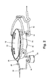
- FIG. 2 shows various elements of the cooking apparatus 10 in greater detail. It should be understood that FIG. 2 is schematic in nature and does not illustrate the particular appearance or configuration that may be used in a commercial implementation of the present invention.
- the cooking chamber or sink 12 is designed to receive water and/or steam depending on the cooking select.
- a water valve 20 is provided on a water inlet supply 22 to regulate the supply of water into the cooking sink 12. Water supplied through the water valve 20 is directed through inlet tubes 26 to inlet housings 24 which are provided along the top, upper edge of the of the cooking sink 12. Water flows into the cooking sink through the inlet ports 28 located along the upper edge of the cooking sink 12.
- a heating element 30 is provided along the bottom surface of the steam generator 10. After water is added into the cooking chamber 12, the heater 30 can be used to heat the water for cooking food items placed in the cooking chamber. Alternatively, food items can be added into the cooking chamber and heated directly by the heating element such that the cooking chamber 12 functions as a pan to braise or brown food items.
- a drain pipe 32 extends from the bottom of the cooking chamber 12 for draining water from the chamber 12.
- a valve 34 is provided for selectively controlling the draining.
- heating lamps may be provided along the upper edge of the cooking chamber 12 or along the lid 14 to supply radiant energy into the cooking chamber 12.
- a steam generator 40 is also provided for introducing steam into the cooking apparatus 10 in accordance with the invention. Water is supplied to the steam generator through the water inlet supply 22 which is controlled by a water valve 42. A steam conduit 44 provides a path for steam to flow from the steam generator 40 to the cooking chamber 12. The steam conduit 44 may be connected to the inlet housing such that steam is introduced from the chamber 12 via the inlet ports 28.
- the steam generator 40 includes a casing or housing 52 which is preferably a plastic material with a low thermal mass.
- the housing 52 defines a steam generation cavity or chamber 54.
- a heater plate 56 forms a bottom wall of the steam generation cavity 54.
- the heater plate 56 is composed by a metallic plate 58 on which a thick film heating element 60 is deposited upon a substrate layer 62 of ceramic material.
- the face of the metallic plate 58 opposite the thick film heating element 60 is directed toward the inner space or steam generation cavity 54.
- the use of a thick film heating element 60 allows for very quick heating as the thermal mass of the heater plate 56 is relatively small. Very fast water heating is also achieved because the thick film heater 60 allows for input of a large amount of energy into the cooking chamber. Finally, the temperature of the thick film heater 60 can be precisely controlled.
- the heater plate 56 is arranged to have a high point 63. As shown in FIG. 3, the heater plate 56 may be mounted in such a way that it is placed on a plane P that is at an angle from the horizontal orientation H. In this way, the heater plate has a high end.
- the heater plate 56 is shown oriented at an angle via the configuration of the housing 52. However, this may be accomplished in any number of ways including through the use of mounting feet extending from the housing or through the use of a specially configured metallic plate 58.
- the present invention is directed to cover any method used for orientating the heater plate at an angle.
- the heater plate may be arranged in other ways to achieve having a high point.
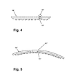
- FIGS. 4 and 5 two alternate embodiments of the heater plate 56 is shown.
- the high point 63' is provided by forming a small upward protrusion or dimple in the heater plate 56'.
- the high point 63" is provided by bowing upwardly the middle portion of the heater plate 56".
- an inlet water opening 66 through which water is added or sprayed into the steam cavity 54.
- the inlet opening 66 is fluidly connected to the water valve 42 for selectively controlling water inlet into the steam cavity 54.
- heat from the heater plate 56 operates to heat water and convert water to steam.
- Steam then exits the steam generator 40 through steam outlet port or opening 68. The steam passes through the steam conduits 44 to the cooking chamber 12.
- a temperature sensor 64 is mounted on the underside of the heater plate 56 at the high point 63 on the heater plate. In this way, the temperature sensor 64 is positioned to sense when the heater plate 56 begins to overheat. As long as sufficient water is present, the heater plate will not overheat. Overheating of the heater plate 56 will occur when the steam generator 40 begins to run dry. Since the highest part of the heater plate 56 will be the first to run dry, the temperature sensor 64 will be able to sense when the heater plate 56 first begins to overheat.
- a similar temperature sensor 64' and 64" can be provided in the alternate embodiments shown in FIG. 4 and 5.
- sensor 64 is designed to improve the likelihood of detecting a temperature rise above the critical heat flux point, but operates only at location 64. It is also possible to measure the current leakage between the heater element 60 (resistive track) and steel plate 58 to measure the critical heat flux temperature over the entire surface of heater plate 56. Current leakage will occur, over a predetermined minimum threshold, only in the event of a high temperature, over threshold condition, such that current leakage is a good measure of over-threshold temperature condition. In this way, two different types of over threshold sensing system can be employed.
- Two key performance measures for the steam generator 40 are: 1) that it produce steam very fast; and 2) that it produce steam efficiently.
- the present invention provides a system to control the temperature and heat transfer of the heater plate 56, the amount of water in contact with the heater plate, and the speed at which the heating plate heats.
- the inventors have discovered that in order for the steam generator 40 of the present invention to be capable of rapidly producing steam, it is beneficial to have a large surface area which is completely covered by water with a heater plate that is at temperature close to critical heat flux.
- Heat flux in this case of steam generation is typically the amount of heat, transferred to a liquid, per unit of time through a unit area.
- the critical heat flux is the condition where the steam generation rate approaches the most efficient possible.
- Boiling heat transfer is a convective process which involves a change of phase from liquid to vapour.
- FIGS. 6a and 6b illustrate pool boiling curve and provide images of various stages in it, respectively.
- the temperature of the heater plate close to the critical heat flux temperature but not exceeding it.
- the critical heat flux temperature is dependent on atmospheric conditions as well as the characteristics of the water used, however it is approximately between 110° C and 140 ° C, but could be higher or lower depending on environmental conditions and water characteristics..
- the heater plate 56 is necessary to arrange the heater plate 56 in such a way that only a small volume of water is sufficient to completely cover the heater plate 56, including the high point 63.
- the angle A at which the heater plate is supported be relatively shallow.
- a steep angle, for example, 20° off horizontal will lead to a relatively deep covering of water over the heater plate on the low end, contributing to a relatively large volume of water.
- the heater plate is supported at an angle A from approximately just slightly greater than 0 to 10° off horizontal, in the case where the heater plate 56 is inclined. In the case where the heater plate 56 is configured in some alternate way to provide a high point, it is also necessary to minimize the amount of total water above the heater plate 56.
- the speed at which the heater plate 56 is heated is a function of heater type.
- the thick film heating element 60 provides for inputting a large amount of energy and extremely rapid heating response due to the low thermal mass of the heater plate 56.
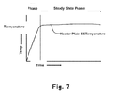
- FIG. 7 it can be seen that the heater plate 56 having the thick film heating element 60 is capable of heating to just below the critical heat flux temperature very rapidly and then entering a steady state temperature.
- control system for the present invention includes a controller or control circuit 70 which analyzes temperature measurement signals from the temperature sensor 64, leakage current and other sensors and controls an electric switch 72 in response.
- the electric switch 72 is arranged between a power supply 74 and the heating element 60. If the control circuit 70 senses that the heater plate 56 is overheating, the supply of power to the heating element 60 can be controlled, as well as flow rate of water entering chamber 54.
- the controller 70 is able to produce in a short period of time (flash boiling) a first amount of steam perceived by the consumer and in the second time guarantee precisely the amount of steam required by the consumer. Looking at FIG. 7, it can be seen that the controller 70 has inputs from 1) the temperature of the sensor 64 placed on the bottom of the thick-film heater on line 73 and the user desired rate of steam on line 75. The controller 70 may also receive input regarding the leakage current as discussed above. The controller outputs include the heater element 60 duty cycle on line 77 and the water valve 42 duty cycle on line 79.
- the supply of water into the steam generator can be separated into two main phases: the fill phase (flash boiling), and the steady-state phase.
- the fill phase is initiated upon start up of steam production to create a water film on the surface of the heater plate 56.
- the controller 70 outputs a water valve duty cycle which pulses the water valve ON and OFF to rapidly provide this water film on the surface of the heater plate 56.
- the controller 70 also outputs a duty cycle to the heater 60 to rapidly raise the temperature of the heater plate 56 to close to the critical heat flux for the water and is regulated for example by a PID temperature controller.
- the steady-state phase starts after the fill phase with a regulation control of the steam flow.
- the correlation between the amount of steam required by the consumer and the heater temperature surface pulse the ON/OFF switch on the inlet water valve 42.
- the steam flow regulation can be simple look-up tables or a more sophisticated closed loop system like a PID.
- the inlet water valve 42 can be cycled for a period of time at the higher rate employed during the fill phase to create again a water film on the entire surface of the heater.
- step 82 the timer is initiated and the water valve 42 is pulsed to supply water into the steam cavity 54.
- the pulse rate for the water valve 42 is MAX_FLOW. Water is inlet in the steam cavity 54 for a predetermined time as shown in steps 84 and 86.
- the controller 70 After an initial time FillPhase_Time, the controller 70 initiates heating the heater plate 56 by pulsing the heating element 60.
- the controller 70 outputs a duty cycle to the heater 60 to rapidly raise the temperature of the heater plate 56 to close to the critical temperature for the water and is regulated for example by a PID temperature controller.
- step 94 the flow rate of the water inlet valve 42 is reduced to a USER_FLOW rate 54 for a predetermined time as shown in step 94.
- This period is the steady-state phase referred to above.
- This steady-state phase continues for the period selected by the user and, as described above, the amount of steam required drives the duty rate of the water valve 42 and the duty rate of the heater 60.
- steps 96 and 98 it can be seen that during the steady state operation, the temperature of the heater plate is monitored and in the event of an over-threshold temperature, an action is taken, such as increasing the rate of pulsing the water inlet valve.
- an action is taken, such as increasing the rate of pulsing the water inlet valve.
- the inlet water valve 42 can be cycled for a period of time at the higher MAX_FLOW employed during the flash-boiling phase to create again a water film on the entire surface of the heater.
- the controller outputs a duty cycle to control the heating element 60.
- This duty cycle rate may be energized in accord with a user input to provide different levels of heat energy input. In this way, it is possible to control the amount of steam produced by the steam generator. To produce large quantities of steam, the heater is cycled at a high duty rate while a low duty cycle will produce less steam.
- the steam generator is able to operate safely with a relatively small amount of water provided above the heater plate 56 by switching the duty cycle of the water valve 42 between a fill phase and a steady state phase.
- This type of system allow water inlet control without the need for expensive and complicated control systems for monitoring the presence of water.
- This method of operation also provides for very fast steam generation. Due to the relatively shallow pool of water provided over the heater plate 56 and high efficiency, the water heats rapidly and quickly is converted to steam.
- the steam generator 40 is shown as part of a cooking apparatus 10 in the present application, it can be appreciated that the steam generator of the present invention may be used in any number of applications.
- the steam generator may be used with a conventional or micro-wave oven.
- the steam generator 40 may also be incorporated as an integral part of a cooking apparatus or oven system.
- the controller 70 of the steam generator 40 may be incorporated as part of the controller for a cooking apparatus.
- the controller 70 may be formed as part of the user interface control 16.
Landscapes
- Engineering & Computer Science (AREA)
- Chemical & Material Sciences (AREA)
- Combustion & Propulsion (AREA)
- Mechanical Engineering (AREA)
- General Engineering & Computer Science (AREA)
- Food Science & Technology (AREA)
- Cookers (AREA)
- Commercial Cooking Devices (AREA)
Abstract
Description
- The present invention relates to a steam generating mechanism for use in a cooking application and more particularly to a steam generator for use with a cooking apparatus, such as a cooking sink, microwave oven or conventional oven, which can provide steam cooking capability.
- It is sometimes preferable for particular kinds of foods to be cooked using steam. Accordingly, conventional ovens and microwaves have sometimes been equipped with a steam generating mechanism in addition to a regular heating means. Additionally, it is known to provide sinks with cooking capabilities including having a steam generator which provides steam into the cooking sink.
- Conventionally there has been introduced a wide variety of steam generating mechanisms into the market, which can be characterized into different categories.
- One type of steam generating mechanism which is typically used in an oven, has a means for providing water into the bottom portion of an oven cavity. An oven heater is installed into the bottom of the oven cavity and operates to heat the water so as to generate steam into the chamber.
- Another type of steam generating mechanism employs a configuration in which the water is injected over a heater to generate steam. US Pat. No. 6,318,246 illustrates such a system, wherein a water supply tube directs water toward a suction side of a fan where air and water is sucked by the fan and is dispersed toward a heater so that water is formed into steam.
- U.S. Pat. No. 4,741,261 discloses another type of steam generating mechanism. In this reference, a steam generator is arranged outside of a cooking pot and is connected to the pot so that steam generated by the steam supply can be directed into the cooking pot. A valve assembly between the steam generator and the cooking pot controls the introduction of steam into the pot.
- According to the invention, a steam generator (40) is provided having a housing for forming a steam generating chamber (54), the housing having a steam outlet port (68). A heater plate (56) is supported by the housing within the steam generating chamber or cavity. A water inlet valve (42) is fluidly connected to the housing for selectively supplying water into the steam generating chamber whereby water is directed to the heater plate for conversion to steam. The heater plate forms a bottom wall of the steam generating chamber and is arranged to have a high point.
- The water inlet valve is opened and closed in accord with a duty cycle which alternates between two phases: a fill phase duty cycle and a steady state duty cycle. The steady state duty cycle is relatively slower than the fill phase duty cycle such that during the fill phase water the level of water in the steam generating chamber rises and in the steady state phase the level of water in the steam generating chamber decreases.
In a boil dry condition (over threshold), the high point of the heater plate begins to overheat first such that a temperature sensor mounted to the heater plate at the high end of the heater plate can operate to prevent overheating of the heater plate. It is also possible to sense for leakage current to allow for safe operation of the steam generator at critical heat flux, thus ensuring a high efficiency and fast steam generation. - [0010] The present invention will be more apparent from the accompanying drawings, which are provided by way of non-limiting example and in which:
- FIG. 1 is a perspective view of a cooking apparatus having a steam generator embodying the principles of the present invention.
- FIG. 2. is a schematic illustration of the cooking apparatus showing the major components of the cooking apparatus, including a steam generator according to the present invention.
- FIG. 3. is a schematic, cross-sectional view of the steam generator.
- FIGS. 4 and 5 illustrate schematically alternate embodiments of the heater plate of the present invention.
- FIG. 6a is a graph showing the pool boiling curve for water at atmospheric pressure.
- FIG. 6b is a schematic illustration of the various stages of the pool boiling curve.
- FIG. 7 is a graph showing the temperature control of the steam generator heater plate in accordance with the present invention.
- FIG. 8 is a schematic illustration of the inputs and outputs of the controller of the present invention.
- FIG. 9 is a flow chart illustrating the operation and control of the steam generator of the present invention.
- With reference to FIG. 1, there is shown a
cooking apparatus 10 having a steam generator in accordance with the present invention. Thecooking apparatus 10 includes of a bowl or sink-like cooking chamber 12 set into an upper surface of a counter top. Alid 14 is provided hingedly supported above thecooking chamber 12. Alternatively, thelid 14 may be a separate element and not hingedly connected to the cooking chamber. Thecooking chamber 12 is designed to receive various types of cooking utensils, such as a perforated basket (not shown). Auser interface 16 which can include a set of controls and indicator lamps, is provided for the cooking apparatus. These controls oruser interface 16 may be preferably located along the peripheral edge of thecooking chamber 12 although they can also be separated from the body of thecooking apparatus 10. Thecooking apparatus 10 may be a "stand alone" device or may be incorporated into a cook top or cooking hob with conventional burners. - FIG. 2 shows various elements of the
cooking apparatus 10 in greater detail. It should be understood that FIG. 2 is schematic in nature and does not illustrate the particular appearance or configuration that may be used in a commercial implementation of the present invention. The cooking chamber orsink 12 is designed to receive water and/or steam depending on the cooking select. Awater valve 20 is provided on awater inlet supply 22 to regulate the supply of water into thecooking sink 12. Water supplied through thewater valve 20 is directed through inlet tubes 26 to inlethousings 24 which are provided along the top, upper edge of the of thecooking sink 12. Water flows into the cooking sink through theinlet ports 28 located along the upper edge of thecooking sink 12. - A
heating element 30 is provided along the bottom surface of thesteam generator 10. After water is added into thecooking chamber 12, theheater 30 can be used to heat the water for cooking food items placed in the cooking chamber. Alternatively, food items can be added into the cooking chamber and heated directly by the heating element such that thecooking chamber 12 functions as a pan to braise or brown food items. Adrain pipe 32 extends from the bottom of thecooking chamber 12 for draining water from thechamber 12. Avalve 34 is provided for selectively controlling the draining. - It is also possible to add other heating type systems to the
cooking apparatus 10. For example, heating lamps (not shown) may be provided along the upper edge of thecooking chamber 12 or along thelid 14 to supply radiant energy into thecooking chamber 12. Alternatively, it is possible to direct MW energy into the cooking chamber. - A
steam generator 40 is also provided for introducing steam into thecooking apparatus 10 in accordance with the invention. Water is supplied to the steam generator through thewater inlet supply 22 which is controlled by awater valve 42. Asteam conduit 44 provides a path for steam to flow from thesteam generator 40 to thecooking chamber 12. Thesteam conduit 44 may be connected to the inlet housing such that steam is introduced from thechamber 12 via theinlet ports 28. - Turning to FIG. 3, the steam generator of the present invention is shown schematically. The
steam generator 40 includes a casing orhousing 52 which is preferably a plastic material with a low thermal mass. Thehousing 52 defines a steam generation cavity orchamber 54. Aheater plate 56 forms a bottom wall of thesteam generation cavity 54. - The
heater plate 56 is composed by ametallic plate 58 on which a thickfilm heating element 60 is deposited upon asubstrate layer 62 of ceramic material. The face of themetallic plate 58 opposite the thickfilm heating element 60 is directed toward the inner space orsteam generation cavity 54. The use of a thickfilm heating element 60 allows for very quick heating as the thermal mass of theheater plate 56 is relatively small. Very fast water heating is also achieved because thethick film heater 60 allows for input of a large amount of energy into the cooking chamber. Finally, the temperature of thethick film heater 60 can be precisely controlled. - The
heater plate 56 is arranged to have ahigh point 63. As shown in FIG. 3, theheater plate 56 may be mounted in such a way that it is placed on a plane P that is at an angle from the horizontal orientation H. In this way, the heater plate has a high end. Theheater plate 56 is shown oriented at an angle via the configuration of thehousing 52. However, this may be accomplished in any number of ways including through the use of mounting feet extending from the housing or through the use of a specially configuredmetallic plate 58. The present invention is directed to cover any method used for orientating the heater plate at an angle. - Alternatively, the heater plate may be arranged in other ways to achieve having a high point. In FIGS. 4 and 5, two alternate embodiments of the
heater plate 56 is shown. In FIG 4, the high point 63' is provided by forming a small upward protrusion or dimple in the heater plate 56'. In FIG 5, thehigh point 63" is provided by bowing upwardly the middle portion of theheater plate 56". - Returning to FIG. 3, it is seen that provided within the
housing 52 is aninlet water opening 66 through which water is added or sprayed into thesteam cavity 54. Theinlet opening 66 is fluidly connected to thewater valve 42 for selectively controlling water inlet into thesteam cavity 54. After water enters thesteam cavity 54, heat from theheater plate 56 operates to heat water and convert water to steam. Steam then exits thesteam generator 40 through steam outlet port oropening 68. The steam passes through thesteam conduits 44 to thecooking chamber 12. - A
temperature sensor 64 is mounted on the underside of theheater plate 56 at thehigh point 63 on the heater plate. In this way, thetemperature sensor 64 is positioned to sense when theheater plate 56 begins to overheat. As long as sufficient water is present, the heater plate will not overheat. Overheating of theheater plate 56 will occur when thesteam generator 40 begins to run dry. Since the highest part of theheater plate 56 will be the first to run dry, thetemperature sensor 64 will be able to sense when theheater plate 56 first begins to overheat. Asimilar temperature sensor 64' and 64" can be provided in the alternate embodiments shown in FIG. 4 and 5. - The inclusion and location of
sensor 64 is designed to improve the likelihood of detecting a temperature rise above the critical heat flux point, but operates only atlocation 64. It is also possible to measure the current leakage between the heater element 60 (resistive track) andsteel plate 58 to measure the critical heat flux temperature over the entire surface ofheater plate 56. Current leakage will occur, over a predetermined minimum threshold, only in the event of a high temperature, over threshold condition, such that current leakage is a good measure of over-threshold temperature condition. In this way, two different types of over threshold sensing system can be employed. - Two key performance measures for the
steam generator 40 are: 1) that it produce steam very fast; and 2) that it produce steam efficiently. In order to achieve these results the present invention provides a system to control the temperature and heat transfer of theheater plate 56, the amount of water in contact with the heater plate, and the speed at which the heating plate heats. Moreover, the inventors have discovered that in order for thesteam generator 40 of the present invention to be capable of rapidly producing steam, it is beneficial to have a large surface area which is completely covered by water with a heater plate that is at temperature close to critical heat flux. - Heat flux in this case of steam generation is typically the amount of heat, transferred to a liquid, per unit of time through a unit area. Generally, one may say that the critical heat flux is the condition where the steam generation rate approaches the most efficient possible. Boiling heat transfer is a convective process which involves a change of phase from liquid to vapour. There are two basic types of boiling: pool boiling and flow boiling. In general there appear to be three distinct regimes in pool boiling, these are the free convective evaporation regime, the nucleate boiling regime, and the film boiling regime. The heat transfer characteristics vary drastically from one regime to another. Nucleate boiling has a great practical value for fast steam generation because of the relatively high heat transfer rates. As the heating surface temperature is increased, vaporization will continue but bubbles will form on the heating surface at nucleation sites. As more and more bubbles break away from the heating surface, the liquid nearby is greatly agitated, resulting in a large increase of the heat transfer rate. However the heat transfer rate cannot be increased indefinitely since at some stage there will be so many bubbles covering the heated surface which will prevent the liquid from reaching the heated surface. Consequently there is a danger of burnout or "boiling crisis". The peak heat flux for nucleate boiling at this point is called the critical heat flux. Typically this point of "critical heat flux" occurs below the Leidenfrost point, or minimum surface temperature to support film boiling, since for film boiling the heated surface is covered with a layer of vapour preventing contact between the liquid and the heated surface. FIGS. 6a and 6b illustrate pool boiling curve and provide images of various stages in it, respectively.
- Accordingly, in order to maximize speed and efficiency, it is desirable to control the temperature of the heater plate close to the critical heat flux temperature but not exceeding it. The critical heat flux temperature is dependent on atmospheric conditions as well as the characteristics of the water used, however it is approximately between 110° C and 140 ° C, but could be higher or lower depending on environmental conditions and water characteristics..
- To promote rapid water heating, especially during initial conditions it is also helpful to have only a small volume of water in contact with the heater plate. To achieve this end, it is necessary to arrange the
heater plate 56 in such a way that only a small volume of water is sufficient to completely cover theheater plate 56, including thehigh point 63. In FIG. 3, it can be understood that it is important to have the angle A at which the heater plate is supported be relatively shallow. A steep angle, for example, 20° off horizontal, will lead to a relatively deep covering of water over the heater plate on the low end, contributing to a relatively large volume of water. Preferably, the heater plate is supported at an angle A from approximately just slightly greater than 0 to 10° off horizontal, in the case where theheater plate 56 is inclined. In the case where theheater plate 56 is configured in some alternate way to provide a high point, it is also necessary to minimize the amount of total water above theheater plate 56. - The speed at which the
heater plate 56 is heated is a function of heater type. In the present invention, the thickfilm heating element 60 provides for inputting a large amount of energy and extremely rapid heating response due to the low thermal mass of theheater plate 56. In FIG. 7, it can be seen that theheater plate 56 having the thickfilm heating element 60 is capable of heating to just below the critical heat flux temperature very rapidly and then entering a steady state temperature. - Tuming now to FIG. 3 and FIG 8, it can be understood that the control system for the present invention includes a controller or
control circuit 70 which analyzes temperature measurement signals from thetemperature sensor 64, leakage current and other sensors and controls anelectric switch 72 in response. Theelectric switch 72 is arranged between apower supply 74 and theheating element 60. If thecontrol circuit 70 senses that theheater plate 56 is overheating, the supply of power to theheating element 60 can be controlled, as well as flow rate ofwater entering chamber 54. - The
controller 70 is able to produce in a short period of time (flash boiling) a first amount of steam perceived by the consumer and in the second time guarantee precisely the amount of steam required by the consumer. Looking at FIG. 7, it can be seen that thecontroller 70 has inputs from 1) the temperature of thesensor 64 placed on the bottom of the thick-film heater online 73 and the user desired rate of steam online 75. Thecontroller 70 may also receive input regarding the leakage current as discussed above. The controller outputs include theheater element 60 duty cycle online 77 and thewater valve 42 duty cycle online 79. - The supply of water into the steam generator can be separated into two main phases: the fill phase (flash boiling), and the steady-state phase. The fill phase is initiated upon start up of steam production to create a water film on the surface of the
heater plate 56. During this phase, thecontroller 70 outputs a water valve duty cycle which pulses the water valve ON and OFF to rapidly provide this water film on the surface of theheater plate 56. During the fill phase, thecontroller 70 also outputs a duty cycle to theheater 60 to rapidly raise the temperature of theheater plate 56 to close to the critical heat flux for the water and is regulated for example by a PID temperature controller. - The steady-state phase starts after the fill phase with a regulation control of the steam flow. The correlation between the amount of steam required by the consumer and the heater temperature surface pulse the ON/OFF switch on the
inlet water valve 42. The steam flow regulation can be simple look-up tables or a more sophisticated closed loop system like a PID. During this phase, if leakage current is sensed or thetemperature sensor 64 indicates an over threshold condition, theinlet water valve 42 can be cycled for a period of time at the higher rate employed during the fill phase to create again a water film on the entire surface of the heater. - The above description can be illustrated in a flow chart as shown in FIG. 9, where the fill phase (flash boiling) is described in steps 80-92. After a steam generation operation is initiated, as shown in
step 80, a timer which can be part of thecontrol circuit 70, is set to zero (TIME = 0), thewater valve 42 andheating element 60 are not energized. Instep 82, the timer is initiated and thewater valve 42 is pulsed to supply water into thesteam cavity 54. The pulse rate for thewater valve 42 is MAX_FLOW. Water is inlet in thesteam cavity 54 for a predetermined time as shown insteps - After an initial time FillPhase_Time, the
controller 70 initiates heating theheater plate 56 by pulsing theheating element 60. Thecontroller 70 outputs a duty cycle to theheater 60 to rapidly raise the temperature of theheater plate 56 to close to the critical temperature for the water and is regulated for example by a PID temperature controller. - After a predetermined time, Fillphase = EndTime, the flow rate of the
water inlet valve 42 is reduced to aUSER_FLOW rate 54 for a predetermined time as shown instep 94. This period is the steady-state phase referred to above. This steady-state phase continues for the period selected by the user and, as described above, the amount of steam required drives the duty rate of thewater valve 42 and the duty rate of theheater 60. - As shown in
steps temperature sensor 64 indicates an over threshold condition, theinlet water valve 42 can be cycled for a period of time at the higher MAX_FLOW employed during the flash-boiling phase to create again a water film on the entire surface of the heater. - As discussed above, the controller outputs a duty cycle to control the
heating element 60. This duty cycle rate may be energized in accord with a user input to provide different levels of heat energy input. In this way, it is possible to control the amount of steam produced by the steam generator. To produce large quantities of steam, the heater is cycled at a high duty rate while a low duty cycle will produce less steam. - It can be seen, therefore, that the steam generator is able to operate safely with a relatively small amount of water provided above the
heater plate 56 by switching the duty cycle of thewater valve 42 between a fill phase and a steady state phase. This type of system allow water inlet control without the need for expensive and complicated control systems for monitoring the presence of water. This method of operation also provides for very fast steam generation. Due to the relatively shallow pool of water provided over theheater plate 56 and high efficiency, the water heats rapidly and quickly is converted to steam. - While the
steam generator 40 is shown as part of acooking apparatus 10 in the present application, it can be appreciated that the steam generator of the present invention may be used in any number of applications. For example, the steam generator may be used with a conventional or micro-wave oven. - Additionally, while the
steam generator 40 has been shown as a "stand alone" type device, the steam generator of the present invention may also be incorporated as an integral part of a cooking apparatus or oven system. In such an integrated system, thecontroller 70 of thesteam generator 40 may be incorporated as part of the controller for a cooking apparatus. For example, thecontroller 70 may be formed as part of theuser interface control 16. - As is apparent from the foregoing specification, the invention is susceptible of being embodied with various alterations and modifications which may differ particularly from those that have been described in the preceding specification and description. It should be understood that we wish to embody within the scope of the patent warranted hereon all such modifications as reasonably and properly come within the scope of our contribution to the art.
Claims (16)
- A steam generator (40) for producing steam, characterized in that
a housing (52) is provided for forming a steam generating chamber (54), the housing having a steam outlet port (68);
a heater plate (56) is supported by the housing within the steam generating chamber energized to a temperature near, but not exceeding, the critical heat flux temperature; and
a water inlet valve (42) fluidly connected to the housing for selectively supplying water into the steam generating chamber whereby water is directed to the heater plate for conversion to steam. - The steam generator (40) as claimed in claim 1, characterized in that the heater plate forms a bottom wall of the steam generating chamber and includes a metallic plate (58) which supports a thick film heating element (60).
- The steam generator (40) as claimed in claim 2, characterized in that the thick film heating element (60) is cycled at a plurality of different duty cycles for generating different levels of heat energy output so that the amount of steam produced by the steam generator may be controlled.
- The steam generator (40) as claimed in claim 1, characterized in that
the heater plate includes a metallic plate (58) which supports a thick film heating element (60),
a controller (70) is provided for outputting a duty cycle to the heating element and using feedback data such that the heating element rapidly raises the temperature of the heater plate to a temperature near, but not exceeding, the critical heat flux. - The steam generator (40) as claimed in claim 1, characterized in that the heater plate (56) forms a bottom wall of the steam generating chamber.
- The steam generator (40) as claimed in claim 5, characterized in that the heater plate (56) is configured to have a high point (63).
- The steam generator (40) as claimed in claim 5, characterized in that the heater plate (56) is supported at an inclined angle from horizontal.
- The steam generator (40) as claimed in claim 7, characterized in that the heater plate (56) is supported at an inclined angle of between 0 and 20 degrees.
- The steam generator (40) as claimed in claim 6, characterized in that a temperature sensor (64) is mounted to the heater plate at the high point.
- The steam generator (40) as claimed in claim 1, characterized in that the water inlet valve (42) is opened and closed in accord with a duty cycle which alternates between two phases.
- The steam generator (40) as claimed in claim 1, characterized in that the water inlet valve (42) is opened and closed in accord with a duty cycle which alternates between a fill phase duty cycle and a steady state duty cycle, wherein the steady state duty cycle is relatively slower than the fill phase duty cycle such that during the fill phase water the level of water in the steam generating chamber rises and in the steady state phase the level of water in the steam generating chamber decreases.
- A method for operating a cooking appliance having a steam generator (40) having a housing (52) which is provided for forming a steam generating chamber (54), the cooking appliance having a controller (70), characterized in that
a water inlet valve (42) supplying water into the steam generating chamber is pulsed in accord with a first duty cycle in order to provide a film of water over a heater plate (56) supported by the housing within the steam generating chamber (54), the heater plate having a thick film heating element (60),
the heating element is energized to rapidly raise the temperature of the heater plate to a temperature near, but not exceeding, the critical heat flux temperature,
after a predetermined time, the water inlet valve is pulsed in accord with a second duty cycle, which is relatively slower than the first duty cycle, to provide a steady state of operation for the steam generator. - The method of operating the cooking appliance as claimed in claim 12, further characterized in that
during the steady state operation the temperature of the heater plate is monitored and in the event of an over-threshold temperature, the rate of pulsing the water inlet valve is increased. - The method of operating the cooking appliance as claimed in claim 12, further characterized in that
during the steady state operation the temperature of the heater plate is monitored and in the event of an over-threshold temperature, the duty cycle of the heating element is changed. - The method of operating the cooking appliance as claimed in claim 12, further characterized in that
the controller receives signals from a temperature sensor (64) located at a high point on the heater plate and changes the control output in the event of an over-threshold temperature. - The method of operating the cooking appliance as claimed in claim 15, further characterized in that
the controller receives a signal indicative of current leakage between the heating element (60) and a metallic plate (58) upon which the heating element is mounted and changes the control output in the event of a signal indicating current leakage.
Priority Applications (5)
| Application Number | Priority Date | Filing Date | Title |
|---|---|---|---|
| ES04105916T ES2320885T3 (en) | 2004-11-19 | 2004-11-19 | STEAM GENERATOR FOR KITCHEN APPLIANCE. |
| EP04105916A EP1658798B1 (en) | 2004-11-19 | 2004-11-19 | Steam generator for cooking apparatus |
| DE602004019658T DE602004019658D1 (en) | 2004-11-19 | 2004-11-19 | Steam generator for cooking appliances |
| CA2526761A CA2526761C (en) | 2004-11-19 | 2005-11-10 | Steam generator for cooking apparatus |
| US11/281,828 US7669591B2 (en) | 2004-11-19 | 2005-11-17 | Steam generator for cooking apparatus |
Applications Claiming Priority (1)
| Application Number | Priority Date | Filing Date | Title |
|---|---|---|---|
| EP04105916A EP1658798B1 (en) | 2004-11-19 | 2004-11-19 | Steam generator for cooking apparatus |
Publications (2)
| Publication Number | Publication Date |
|---|---|
| EP1658798A1 true EP1658798A1 (en) | 2006-05-24 |
| EP1658798B1 EP1658798B1 (en) | 2009-02-25 |
Family
ID=34929891
Family Applications (1)
| Application Number | Title | Priority Date | Filing Date |
|---|---|---|---|
| EP04105916A Ceased EP1658798B1 (en) | 2004-11-19 | 2004-11-19 | Steam generator for cooking apparatus |
Country Status (5)
| Country | Link |
|---|---|
| US (1) | US7669591B2 (en) |
| EP (1) | EP1658798B1 (en) |
| CA (1) | CA2526761C (en) |
| DE (1) | DE602004019658D1 (en) |
| ES (1) | ES2320885T3 (en) |
Cited By (17)
| Publication number | Priority date | Publication date | Assignee | Title |
|---|---|---|---|---|
| EP1905331A1 (en) * | 2006-09-28 | 2008-04-02 | Samsung Electronics Co., Ltd. | Water level sensing unit, steam generator having the same, and heating cooking apparatus having the steam generator |
| EP1905330A1 (en) * | 2006-09-28 | 2008-04-02 | Samsung Electronics Co., Ltd. | Steam generator and heating cooking apparatus having the same |
| DE102007017932A1 (en) | 2007-04-13 | 2008-10-23 | Miele & Cie. Kg | Steam generator for a household appliance that can be heated by means of a heat accumulator |
| WO2010134930A1 (en) * | 2009-05-16 | 2010-11-25 | Ideas Well Done Llc | Food steamer containers with sequential ohmic water heating |
| DE102009044053A1 (en) | 2009-09-18 | 2011-05-05 | Miele & Cie. Kg | Steam generator for a household appliance |
| WO2011117659A1 (en) * | 2010-03-26 | 2011-09-29 | Strix Limited | Steam cooking appliances |
| WO2012089469A1 (en) * | 2010-12-29 | 2012-07-05 | Arcelik Anonim Sirketi | A cooking device comprising a steam generator |
| DE102014206281A1 (en) * | 2014-04-02 | 2015-10-08 | BSH Hausgeräte GmbH | Operating an evaporator of a household appliance |
| DE102014210669A1 (en) | 2014-06-05 | 2015-12-17 | BSH Hausgeräte GmbH | Evaporator |
| EP2993408A1 (en) * | 2014-09-02 | 2016-03-09 | Miele & Cie. KG | Cooking device and method for operating the same |
| DE102015215768A1 (en) | 2015-08-19 | 2017-02-23 | BSH Hausgeräte GmbH | Household steamer |
| EP3176509A1 (en) * | 2015-12-01 | 2017-06-07 | Electrolux Appliances Aktiebolag | Cooking hob with steam generator |
| WO2018219709A1 (en) * | 2017-05-31 | 2018-12-06 | Electrolux Appliances Aktiebolag | Cooker with vapor generator |
| EP2390587B1 (en) * | 2010-05-27 | 2019-07-17 | BSH Hausgeräte GmbH | Cooking device with a steam generation function |
| WO2020120324A1 (en) * | 2018-12-12 | 2020-06-18 | Electrolux Appliances Aktiebolag | Method for controlling a steam generating system for a domestic steam cooking oven and steam generating system |
| DE102019103783A1 (en) * | 2019-02-14 | 2020-08-20 | Rational Aktiengesellschaft | Steam generator for a cooking appliance, cooking appliance and method for generating steam |
| EP3736502A1 (en) * | 2019-05-10 | 2020-11-11 | Electrolux Appliances Aktiebolag | Cooking hob integrated with steam system |
Families Citing this family (29)
| Publication number | Priority date | Publication date | Assignee | Title |
|---|---|---|---|---|
| JP2010502261A (en) * | 2006-08-29 | 2010-01-28 | パク、カン−ス | Cookware using steam |
| US20080223221A1 (en) * | 2007-03-12 | 2008-09-18 | Schimpf Mark J | Steam generator and steam chamber oven insert for converting conventional home oven to steam injected bread baking oven |
| ES2512515T3 (en) * | 2007-11-28 | 2014-10-24 | Whirlpool Corporation | Method to control the humidity level in a cooking oven |
| EP2326229B1 (en) * | 2008-07-21 | 2018-03-28 | LG Electronics Inc. | A steam head for cleaner |
| KR101528937B1 (en) * | 2009-05-11 | 2015-06-15 | 엘지전자 주식회사 | Cooking equipment |
| KR101609390B1 (en) * | 2009-05-11 | 2016-04-05 | 엘지전자 주식회사 | Cooker |
| RU2531415C2 (en) * | 2010-04-28 | 2014-10-20 | Шарп Кабусики Кайся | Cooking device |
| GB201017461D0 (en) | 2010-10-15 | 2010-12-01 | Strix Ltd | Electric steam generation |
| US9150997B2 (en) * | 2011-08-22 | 2015-10-06 | Lg Electronics Inc. | Home appliance including steam generator and controlling method of the same |
| US9371841B2 (en) | 2012-03-05 | 2016-06-21 | Electrolux Home Products, Inc. | Safety arrangement for an integrated heater, pump, and motor for an appliance |
| KR102244526B1 (en) * | 2014-11-21 | 2021-04-26 | 엘지전자 주식회사 | Cooker |
| US10208964B2 (en) * | 2014-12-05 | 2019-02-19 | Illinois Tool Works Inc. | Steam cooking oven and method |
| US10314315B2 (en) * | 2015-02-03 | 2019-06-11 | Lbc Bakery Equipment, Inc. | Convection oven with linear counter-flow heat exchanger |
| US20170095105A1 (en) * | 2015-10-05 | 2017-04-06 | Joseph R. Clark | Mini steam generator for cooking food, modular cooking appliance, and modular food preparation station |
| FR3046924B1 (en) * | 2016-01-21 | 2018-01-12 | Seb S.A. | METHOD FOR COOKING A FOOD |
| US10281157B2 (en) | 2016-02-10 | 2019-05-07 | Wolf Appliance, Inc. | Gas cooktop with integrated wok |
| USD812415S1 (en) * | 2016-02-10 | 2018-03-13 | Wolf Appliance, Inc. | Wok burner assembly integrated with a gas cooktop |
| KR101975196B1 (en) * | 2017-05-17 | 2019-05-07 | 엘지전자 주식회사 | Cooking apparatus |
| CN111093389A (en) * | 2017-06-21 | 2020-05-01 | 皇家飞利浦有限公司 | Apparatus and method for preparing food puree |
| DE202018006410U1 (en) | 2017-08-09 | 2020-04-23 | Sharkninja Operating Llc | Cooking device and components thereof |
| WO2020176477A1 (en) | 2019-02-25 | 2020-09-03 | Sharkninja Operating Llc | Cooking system with guard |
| US20190254476A1 (en) | 2019-02-25 | 2019-08-22 | Sharkninja Operating Llc | Cooking device and components thereof |
| CN110162125B (en) * | 2019-06-05 | 2024-08-27 | 江苏拓米洛高端装备股份有限公司 | Humidity creation system and method and device for controlling the humidity creation system |
| US11647861B2 (en) | 2020-03-30 | 2023-05-16 | Sharkninja Operating Llc | Cooking device and components thereof |
| CN113545663B (en) * | 2021-08-04 | 2022-09-06 | 广东美的厨房电器制造有限公司 | Control method, control device, cooking device and storage medium |
| CN113397373B (en) * | 2021-08-04 | 2023-04-14 | 杭州老板电器股份有限公司 | Control method and system for steam generator of steam box |
| CN115268538B (en) * | 2022-07-11 | 2024-04-05 | 宁波新芝生物科技股份有限公司 | Synchronous PID control device and method for water temperature and flow |
| CN115264385A (en) * | 2022-08-16 | 2022-11-01 | 陈文生 | Pipeline steam heating type hot dish device |
| CN118031414B (en) * | 2024-04-11 | 2024-06-11 | 厦门宝益科技有限公司 | Thick film heating device capable of efficiently maintaining benign heat exchange of medium |
Citations (5)
| Publication number | Priority date | Publication date | Assignee | Title |
|---|---|---|---|---|
| DE3703814A1 (en) * | 1987-02-07 | 1988-08-18 | Buderus Kuechentechnik | Method for operating a cooking device that can be heated with a hot-air generator and a steam generator |
| EP0508942A2 (en) * | 1991-04-12 | 1992-10-14 | Condair AG | Method of and means for controlling a steam generator |
| DE4309240A1 (en) * | 1993-03-23 | 1994-09-29 | Ego Elektro Blanc & Fischer | Steam generator with an evaporating chamber |
| GB2325396A (en) * | 1997-05-19 | 1998-11-25 | Otter Controls Ltd | Heating element supplied with electricity via spring contacts |
| JP2002125858A (en) * | 2000-10-23 | 2002-05-08 | Tokyo Gas Co Ltd | Griddle |
Family Cites Families (5)
| Publication number | Priority date | Publication date | Assignee | Title |
|---|---|---|---|---|
| DE7911823U1 (en) | 1979-04-23 | 1979-07-26 | A-Z Ausruestung Und Zubehoer Gmbh & Co, Kg, 5628 Heiligenhaus | Washing machine with transport lock |
| US4624117A (en) | 1985-02-05 | 1986-11-25 | Whirlpool Corporation | Removable shipping restraint system for appliances |
| DE4428197C2 (en) | 1994-08-09 | 1999-10-21 | Bsh Bosch Siemens Hausgeraete | Electrically operated washing machine |
| DE19629884B4 (en) | 1996-07-24 | 2006-04-13 | BSH Bosch und Siemens Hausgeräte GmbH | Electrically operated washing machine |
| US6453802B1 (en) * | 2001-03-27 | 2002-09-24 | Market Forge Industries, Inc. | Connectionless food steamer with automatic electric steam trap |
-
2004
- 2004-11-19 ES ES04105916T patent/ES2320885T3/en not_active Expired - Lifetime
- 2004-11-19 EP EP04105916A patent/EP1658798B1/en not_active Ceased
- 2004-11-19 DE DE602004019658T patent/DE602004019658D1/en not_active Expired - Lifetime
-
2005
- 2005-11-10 CA CA2526761A patent/CA2526761C/en not_active Expired - Fee Related
- 2005-11-17 US US11/281,828 patent/US7669591B2/en not_active Expired - Fee Related
Patent Citations (5)
| Publication number | Priority date | Publication date | Assignee | Title |
|---|---|---|---|---|
| DE3703814A1 (en) * | 1987-02-07 | 1988-08-18 | Buderus Kuechentechnik | Method for operating a cooking device that can be heated with a hot-air generator and a steam generator |
| EP0508942A2 (en) * | 1991-04-12 | 1992-10-14 | Condair AG | Method of and means for controlling a steam generator |
| DE4309240A1 (en) * | 1993-03-23 | 1994-09-29 | Ego Elektro Blanc & Fischer | Steam generator with an evaporating chamber |
| GB2325396A (en) * | 1997-05-19 | 1998-11-25 | Otter Controls Ltd | Heating element supplied with electricity via spring contacts |
| JP2002125858A (en) * | 2000-10-23 | 2002-05-08 | Tokyo Gas Co Ltd | Griddle |
Non-Patent Citations (1)
| Title |
|---|
| PATENT ABSTRACTS OF JAPAN vol. 2002, no. 09 4 September 2002 (2002-09-04) * |
Cited By (33)
| Publication number | Priority date | Publication date | Assignee | Title |
|---|---|---|---|---|
| US7989737B2 (en) | 2006-09-28 | 2011-08-02 | Samsung Electronics Co., Ltd. | Steam generator and heating cooking apparatus having the same |
| US7856875B2 (en) | 2006-09-28 | 2010-12-28 | Samsung Electronics Co., Ltd. | Water level sensing unit, steam generator having the same, and heating cooking apparatus having the steam generator |
| EP1905331A1 (en) * | 2006-09-28 | 2008-04-02 | Samsung Electronics Co., Ltd. | Water level sensing unit, steam generator having the same, and heating cooking apparatus having the steam generator |
| KR101041077B1 (en) * | 2006-09-28 | 2011-06-13 | 삼성전자주식회사 | Steam generator and heating cooking device having same |
| EP1905330A1 (en) * | 2006-09-28 | 2008-04-02 | Samsung Electronics Co., Ltd. | Steam generator and heating cooking apparatus having the same |
| CN101152049B (en) * | 2006-09-28 | 2011-09-07 | 三星电子株式会社 | Steam generator and heating cooking apparatus having the same |
| WO2008125268A3 (en) * | 2007-04-13 | 2012-01-05 | Miele & Cie. Kg | Steam generator for a household appliance, heatable using a heat accumulator |
| DE102007017932A1 (en) | 2007-04-13 | 2008-10-23 | Miele & Cie. Kg | Steam generator for a household appliance that can be heated by means of a heat accumulator |
| US8285128B2 (en) | 2007-04-13 | 2012-10-09 | Miele & Cie. Kg | Steam generator for a household appliance, heatable using a heat accumulator |
| WO2010134930A1 (en) * | 2009-05-16 | 2010-11-25 | Ideas Well Done Llc | Food steamer containers with sequential ohmic water heating |
| US8525081B2 (en) | 2009-05-16 | 2013-09-03 | Wood Stone Ideas, Llc | Food steamer containers with sequential ohmic water heating |
| DE102009044053A1 (en) | 2009-09-18 | 2011-05-05 | Miele & Cie. Kg | Steam generator for a household appliance |
| EP2298140A3 (en) * | 2009-09-18 | 2011-07-06 | Miele & Cie. KG | Steam unit for a domestic appliance |
| WO2011117659A1 (en) * | 2010-03-26 | 2011-09-29 | Strix Limited | Steam cooking appliances |
| EP2390587B1 (en) * | 2010-05-27 | 2019-07-17 | BSH Hausgeräte GmbH | Cooking device with a steam generation function |
| WO2012089469A1 (en) * | 2010-12-29 | 2012-07-05 | Arcelik Anonim Sirketi | A cooking device comprising a steam generator |
| CN103270373A (en) * | 2010-12-29 | 2013-08-28 | 阿塞里克股份有限公司 | A cooking device comprising a steam generator |
| CN103270373B (en) * | 2010-12-29 | 2015-11-25 | 阿塞里克股份有限公司 | Comprise the cooking device of steam generator |
| DE102014206281A1 (en) * | 2014-04-02 | 2015-10-08 | BSH Hausgeräte GmbH | Operating an evaporator of a household appliance |
| US10349775B2 (en) | 2014-04-02 | 2019-07-16 | BSH Hausgeräte GmbH | Operation of a vaporizer of a domestic appliance |
| DE102014210669A1 (en) | 2014-06-05 | 2015-12-17 | BSH Hausgeräte GmbH | Evaporator |
| EP2993408A1 (en) * | 2014-09-02 | 2016-03-09 | Miele & Cie. KG | Cooking device and method for operating the same |
| DE102015215768A1 (en) | 2015-08-19 | 2017-02-23 | BSH Hausgeräte GmbH | Household steamer |
| CN108291725B (en) * | 2015-12-01 | 2020-04-21 | 伊莱克斯家用电器股份公司 | Cooking hob with a steam generator |
| CN108291725A (en) * | 2015-12-01 | 2018-07-17 | 伊莱克斯家用电器股份公司 | cooking stove with steam generator |
| WO2017092988A1 (en) * | 2015-12-01 | 2017-06-08 | Electrolux Appliances Aktiebolag | Cooking hob with steam generator |
| EP3176509A1 (en) * | 2015-12-01 | 2017-06-07 | Electrolux Appliances Aktiebolag | Cooking hob with steam generator |
| WO2018219709A1 (en) * | 2017-05-31 | 2018-12-06 | Electrolux Appliances Aktiebolag | Cooker with vapor generator |
| CN108980907A (en) * | 2017-05-31 | 2018-12-11 | 伊莱克斯家用电器股份公司 | Cooking stove |
| WO2020120324A1 (en) * | 2018-12-12 | 2020-06-18 | Electrolux Appliances Aktiebolag | Method for controlling a steam generating system for a domestic steam cooking oven and steam generating system |
| US12044401B2 (en) | 2018-12-12 | 2024-07-23 | Electrolux Appliances Aktiebolag | Method for controlling a steam generating system for a domestic steam cooking oven and steam generating system |
| DE102019103783A1 (en) * | 2019-02-14 | 2020-08-20 | Rational Aktiengesellschaft | Steam generator for a cooking appliance, cooking appliance and method for generating steam |
| EP3736502A1 (en) * | 2019-05-10 | 2020-11-11 | Electrolux Appliances Aktiebolag | Cooking hob integrated with steam system |
Also Published As
| Publication number | Publication date |
|---|---|
| US7669591B2 (en) | 2010-03-02 |
| US20060108433A1 (en) | 2006-05-25 |
| EP1658798B1 (en) | 2009-02-25 |
| CA2526761C (en) | 2013-04-23 |
| DE602004019658D1 (en) | 2009-04-09 |
| CA2526761A1 (en) | 2006-05-19 |
| ES2320885T3 (en) | 2009-05-29 |
Similar Documents
| Publication | Publication Date | Title |
|---|---|---|
| CA2526761C (en) | Steam generator for cooking apparatus | |
| EP2187130B1 (en) | Vapor cooker | |
| KR101931364B1 (en) | Steam generator and cooker having the same | |
| US9788678B2 (en) | Heating cooker | |
| CN101221063A (en) | Water level sensor, steam generator, heating cooker and control method thereof | |
| TWI359647B (en) | ||
| KR102126485B1 (en) | Electronic cooking device with a steam generating apparatus | |
| CN104510325A (en) | Electric cooker and control method thereof | |
| EP2088370A1 (en) | Cooking oven comprising steam generating system | |
| CN100436948C (en) | Control method of microwave oven | |
| JP2003262338A (en) | Superheat steam cooking device and steam generating device | |
| KR20200074079A (en) | Electronic cooking device with a steam generating apparatus | |
| CN1969723A (en) | Steam cooking apparatus | |
| KR100826925B1 (en) | Heating cooker and control method | |
| KR100526210B1 (en) | Steam cooking apparatus | |
| JP2017035322A (en) | rice cooker | |
| JP3082689B2 (en) | Electric rice cooker | |
| JP2018201692A (en) | Cooker | |
| KR100538173B1 (en) | Superheated steam cooking apparatus | |
| JP2001211999A (en) | rice cooker | |
| JP2008267668A (en) | Cooker | |
| JPH06121734A (en) | Electric rice cooker | |
| JP2004049676A (en) | rice cooker | |
| CN120848618A (en) | Cooking appliance control method and cooking appliance | |
| JPH05253059A (en) | Energy saving type steamer |
Legal Events
| Date | Code | Title | Description |
|---|---|---|---|
| PUAI | Public reference made under article 153(3) epc to a published international application that has entered the european phase |
Free format text: ORIGINAL CODE: 0009012 |
|
| AK | Designated contracting states |
Kind code of ref document: A1 Designated state(s): AT BE BG CH CY CZ DE DK EE ES FI FR GB GR HU IE IS IT LI LU MC NL PL PT RO SE SI SK TR |
|
| AX | Request for extension of the european patent |
Extension state: AL HR LT LV MK YU |
|
| 17P | Request for examination filed |
Effective date: 20061026 |
|
| 17Q | First examination report despatched |
Effective date: 20061208 |
|
| AKX | Designation fees paid |
Designated state(s): DE ES FR GB IT |
|
| GRAP | Despatch of communication of intention to grant a patent |
Free format text: ORIGINAL CODE: EPIDOSNIGR1 |
|
| GRAS | Grant fee paid |
Free format text: ORIGINAL CODE: EPIDOSNIGR3 |
|
| GRAA | (expected) grant |
Free format text: ORIGINAL CODE: 0009210 |
|
| AK | Designated contracting states |
Kind code of ref document: B1 Designated state(s): DE ES FR GB IT |
|
| REG | Reference to a national code |
Ref country code: GB Ref legal event code: FG4D |
|
| REF | Corresponds to: |
Ref document number: 602004019658 Country of ref document: DE Date of ref document: 20090409 Kind code of ref document: P |
|
| REG | Reference to a national code |
Ref country code: ES Ref legal event code: FG2A Ref document number: 2320885 Country of ref document: ES Kind code of ref document: T3 |
|
| PLBE | No opposition filed within time limit |
Free format text: ORIGINAL CODE: 0009261 |
|
| STAA | Information on the status of an ep patent application or granted ep patent |
Free format text: STATUS: NO OPPOSITION FILED WITHIN TIME LIMIT |
|
| 26N | No opposition filed |
Effective date: 20091126 |
|
| REG | Reference to a national code |
Ref country code: FR Ref legal event code: PLFP Year of fee payment: 12 |
|
| REG | Reference to a national code |
Ref country code: FR Ref legal event code: PLFP Year of fee payment: 13 |
|
| PGFP | Annual fee paid to national office [announced via postgrant information from national office to epo] |
Ref country code: ES Payment date: 20161011 Year of fee payment: 13 |
|
| REG | Reference to a national code |
Ref country code: FR Ref legal event code: PLFP Year of fee payment: 14 |
|
| REG | Reference to a national code |
Ref country code: FR Ref legal event code: PLFP Year of fee payment: 15 |
|
| PG25 | Lapsed in a contracting state [announced via postgrant information from national office to epo] |
Ref country code: ES Free format text: LAPSE BECAUSE OF NON-PAYMENT OF DUE FEES Effective date: 20171120 |
|
| PGFP | Annual fee paid to national office [announced via postgrant information from national office to epo] |
Ref country code: GB Payment date: 20210930 Year of fee payment: 18 |
|
| PGFP | Annual fee paid to national office [announced via postgrant information from national office to epo] |
Ref country code: DE Payment date: 20210929 Year of fee payment: 18 Ref country code: FR Payment date: 20211109 Year of fee payment: 18 |
|
| PGFP | Annual fee paid to national office [announced via postgrant information from national office to epo] |
Ref country code: IT Payment date: 20211012 Year of fee payment: 18 |
|
| REG | Reference to a national code |
Ref country code: DE Ref legal event code: R119 Ref document number: 602004019658 Country of ref document: DE |
|
| GBPC | Gb: european patent ceased through non-payment of renewal fee |
Effective date: 20221119 |
|
| PG25 | Lapsed in a contracting state [announced via postgrant information from national office to epo] |
Ref country code: IT Free format text: LAPSE BECAUSE OF NON-PAYMENT OF DUE FEES Effective date: 20221119 Ref country code: GB Free format text: LAPSE BECAUSE OF NON-PAYMENT OF DUE FEES Effective date: 20221119 Ref country code: DE Free format text: LAPSE BECAUSE OF NON-PAYMENT OF DUE FEES Effective date: 20230601 |
|
| PG25 | Lapsed in a contracting state [announced via postgrant information from national office to epo] |
Ref country code: FR Free format text: LAPSE BECAUSE OF NON-PAYMENT OF DUE FEES Effective date: 20221130 |