EP1659076A1 - Handling & stacking support for open-sided container - Google Patents
Handling & stacking support for open-sided container Download PDFInfo
- Publication number
- EP1659076A1 EP1659076A1 EP05257114A EP05257114A EP1659076A1 EP 1659076 A1 EP1659076 A1 EP 1659076A1 EP 05257114 A EP05257114 A EP 05257114A EP 05257114 A EP05257114 A EP 05257114A EP 1659076 A1 EP1659076 A1 EP 1659076A1
- Authority
- EP
- European Patent Office
- Prior art keywords
- post
- container
- rail
- handling
- top rail
- Prior art date
- Legal status (The legal status is an assumption and is not a legal conclusion. Google has not performed a legal analysis and makes no representation as to the accuracy of the status listed.)
- Granted
Links
Images


Classifications
-
- B—PERFORMING OPERATIONS; TRANSPORTING
- B65—CONVEYING; PACKING; STORING; HANDLING THIN OR FILAMENTARY MATERIAL
- B65D—CONTAINERS FOR STORAGE OR TRANSPORT OF ARTICLES OR MATERIALS, e.g. BAGS, BARRELS, BOTTLES, BOXES, CANS, CARTONS, CRATES, DRUMS, JARS, TANKS, HOPPERS, FORWARDING CONTAINERS; ACCESSORIES, CLOSURES, OR FITTINGS THEREFOR; PACKAGING ELEMENTS; PACKAGES
- B65D90/00—Component parts, details or accessories for large containers
- B65D90/02—Wall construction
- B65D90/021—Flexible side walls or doors
-
- B—PERFORMING OPERATIONS; TRANSPORTING
- B65—CONVEYING; PACKING; STORING; HANDLING THIN OR FILAMENTARY MATERIAL
- B65D—CONTAINERS FOR STORAGE OR TRANSPORT OF ARTICLES OR MATERIALS, e.g. BAGS, BARRELS, BOTTLES, BOXES, CANS, CARTONS, CRATES, DRUMS, JARS, TANKS, HOPPERS, FORWARDING CONTAINERS; ACCESSORIES, CLOSURES, OR FITTINGS THEREFOR; PACKAGING ELEMENTS; PACKAGES
- B65D88/00—Large containers
- B65D88/02—Large containers rigid
- B65D88/12—Large containers rigid specially adapted for transport
- B65D88/127—Large containers rigid specially adapted for transport open-sided container, i.e. having substantially the whole side free to provide access, with or without closures
-
- B—PERFORMING OPERATIONS; TRANSPORTING
- B65—CONVEYING; PACKING; STORING; HANDLING THIN OR FILAMENTARY MATERIAL
- B65D—CONTAINERS FOR STORAGE OR TRANSPORT OF ARTICLES OR MATERIALS, e.g. BAGS, BARRELS, BOTTLES, BOXES, CANS, CARTONS, CRATES, DRUMS, JARS, TANKS, HOPPERS, FORWARDING CONTAINERS; ACCESSORIES, CLOSURES, OR FITTINGS THEREFOR; PACKAGING ELEMENTS; PACKAGES
- B65D90/00—Component parts, details or accessories for large containers
- B65D90/0026—Corner fittings characterised by shape, configuration or number of openings
Definitions
- an open-sided container features handling fittings carried by a longitudinal top or roof rail, at a span intermediate corner end posts and supported (from below) by an inclined post, strut, or brace.
- Support posts could be of cranked or offset profile at an upper end, for attachment to a top rail carrying a handling fitting at a point inset from and inboard of a post lower end and from one side of and/or below a handling fitting.
- a support post between top and bottom rails could feature a lateral offshoot, strut or brace at an upper post end to a top rail and/or handling fitting carried by a top rail.
- a straight post between upper and lower rails could be fitted with a supplementary cranked or offset arm, strut or brace, to a top rail and/or handling fitting carried by a top rail.
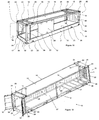
- Figure 1 shows a container 10 with base 12, roof 13 supported on longitudinal top rails 14, and intermediate headers 15, front end frame 16, rear end frame 17 incorporating a pair of doors 18, floor 19 comprising typically timber boards laid on transverse steel channels 20 spanning longitudinal bottom rails 21 corner posts 22, 23 located at each of the four corners incorporating known corner castings 24 at top and bottom.
- Posts 22 at the front end are typically joined by a corrugated steel wall panel 60 closing off the front end.
- Intermediate of the corner castings 24 are top handling fittings 25, interconnected transversely by header 15 and bottom handling fittings 26 incorporated within bottom rails 21 and connected transversely by intermediate sill 20.
- a stub wall 29 - fitted to one or both sides of the container - with intermediate post 30 satisfies that end.
- this can be mitigated by making the stub wall 29 short of a direct support line between fittings 25, 26 - as shown on the near side of the Figure 1, yet still allow a wider stub wall 29' as depicted on the other side of the container 10.
- a single post 31 connected to - or able to abut - a position on header 15 and sill 20.
- Post 31 if not permanently fixed to 15 header and sill 20, can be removable, or movable by sliding or hinging to allow access for cargo removal and loading when stacking is not required.
- Lifting forces acting through fittings 25 or 26 are supported either by connection of the post 31 to header 15 and sill 20 via pins, hinges, or other connections able to generate tension in the post 31.
- header 15 and sill 20 might be supported by top rail 14 and/or bottom rail 21, either fully or in part load-sharing with intermediate post 31.
- Lifting forces upon such containers are generally less than half stacking forces.
- post 31 could be removed - allowing clearer load access.
- Post 31 might not necessarily be located directly between header 15 and sill 20, rather but to one side or end - with necessary structural and mechanical provision by interconnection for stacking and/or lifting forces.
- Two or more posts 31 might be fitted for added strength or for more convenient location.
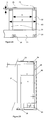
- posts 31 might be fitted near the underside of fittings 25, and spaced apart from corner posts 22 a distance ⁇ D', to allow free movement in and out of the container 10 of pallets of known width a little less than 'D' typically 1200mm and 8OOmm in Europe and 1.18m in Australia.
- the distance' D' might apply between post 31 and panel 60 shown in broken line - the distance 'D' being denoted (D').
- Pallets are then withdrawn by rotation and side shifting, past post 31, but enabling such pallets to be unloaded from either side.
- a clearance 'C' denoted by arrows between post 31 and header 15, or top rail 14 (or sill 20 and bottom rail 21 ) could be some 10 to 30mm. Clearance 'C' is useful to accommodate movement of post 31 into position.
- top fittings 25 When lifting loads are applied through top fittings 25, the header 15 and/or top rail 14 deflect upward until container 10 begins to be lifted clear of the ground or other support. In this mode, clearance 'C' would simply increase and top rail 14, corner posts 22, bottom rail 21 strain until supporting the lift.
- post 31 can be relieved of up to 50% of the stacking load and thus be conveniently of lighter weight construction than otherwise.
- a spigot 32 is fixed to the rail 14 via plate 33.
- a hole plate 34 is fixed to post 21 with hole 35 slotted to provide clearance above and/or below the spigot 32, of the order 10 to 20mm. making opening and closing or movement of the post 31 easier.
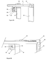
- post 31 is hinged to sill and header - (the following arrangements being illustrated at the post top and largely mirrored yet adapted at the bottom sill) - a hinge pin 36 might be offset on an arm 37 or cantilevered as shown in Figure 4 from a stacking abutment 38 - in this example part of a longitudinal beam 39 spanning front end header 40* and intermediate header 25/45*.
- Post 31 can be moved from a stacking position about axis 41 of hinge pin 36 clear of cargo movements when required
- post 31 might comprise a solid panel hinged to allow it to be positioned in alternative locations allowing free movement of pallets 42 in the transverse direction and maximising width (space) for longer cargo, such as 12m pipes to be loaded through the sides, with post 31 turned to position 31'.
- handling of containers can be by a side frame 43 mounted on a fork lift truck 44, which engages the fittings 25 through known twist-locks 47.
- handling frame 43 requires an abutment 46 near the base 12 of the container.
- FIG. 6 shows such a frame and an abutment surface formed by abutment plate 48 fixed to the bottom side rail 21.
- side curtain 28 When fitted, side curtain 28 is shown in section line coming down past the level of floor 19 and being tucked in behind abutment plate 48, for protection from puncture by handling frame abutment 46. If post 31 is fitted close enough under fittings 25, and curtain 18 is taken behind, post 31 can itself serve as such an abutment surface.
- top rail 15 can be reinforced by a diagonal bracing struts 54 back to corner posts 22 to assist in the structural requirements of lifting and stacking, whilst bearing in mind that flexibility of the structure must be matched with clearance 'C'.
- Strut 54 might be pin-jointed to top rail 15 and corner post 22 as illustrated (and thus be (re)movable to position 54' for cargo access, or be fixed permanently.
- Figure 1 shows in the rear far side stub wall a 'letter box' opening 58, to allow insertion of fork truck tines under a pallet (not shown), sited adjacent to the stub wall.
- post 31 can be of chosen section - either slim or bulky according to geometric space requirements of cargo.
- hinge 46 might be mounted not on header 15 and sill 20, but on some other location to suit cargo and operating needs.
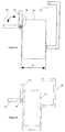
- Figure 7 is a section through post 22 - with the location of fittings 25, 26 drawn and the known top and underside elongate handling aperture 40** shown.
- Post 22/52* comprises one or more pressings to form a composite structure terminating at the front face with end panel 51 and at the side a reinforcement 52 located underneath fitting 25.
- Fitting 25 might be extended, as shown in broken line, to allow a longer aperture 40'** to be formed in it, to aid cleaning and location of handling devices and thus enable post 22 to be shortened back to 52', thereby increasing the side access dimension between end posts and/or stub walls.
- Figure 8 shows a side elevation of an alternative where post 31 is attached by a pivot 55 to top rail 14 and keyed to bottom side rail 21 by a spigot 56, which engages a hole plate 57 seen in section, fixed to the side rail.
- a pallet 64 is depicted blocked from removal by post 12 and post 31'.
- Figure 9 shows a post 31 which is inclined to the vertical. It aims to meet close to top fitting 25 and fully support a slender top rail 14 against stacking and lifting loads, yet make use of a more robust bottom rail 21, by cutting back to enlarge the side opening at the level of floor 19.
- Figure 10 illustrates an improved seal arrangement.
- Post 31 is formed as part of a rectangular door 70, attached to post 22 at hinges 71.
- a double-lipped gasket 73 which seals a gap between closed door 70 and top rail 14, corner post 22 and bottom side rail 21.
- side rail 75 is extended down to line 74 to come closer to the top of door edge 72 and engage gasket 73.
- curtain 76 Attached to side rail 75 is curtain 76 - which is depicted transparent for ease of illustration - drawn over post 31, with its perimeter in drawn position 76'.
- Over curtain 76 is shown a rubber pelmet 77, fixed to side rail 75 and terminating along its bottom edge at line 79 closely level with an edge 78 of side rail 75.
- a conventional door cam and keep arrangement 84 secures the door to the side frame and can be arranged to take lifting loads through fittings 15.
- curtain 76 might be reinforced by a blade 81* or sheet of a resilient low friction material - perhaps of a triangular shaped dense neoprene foam or rubber, so that as curtain 76 is drawn closed - in this example to the left, it can slide easily between pelmet and door.
- Figure 11 shows a similar view to Figure 6 with a drop door 82, attached by hinges to bottom side rail 21.
- Door 82 is locked by some means (not shown) in a vertical position at which it serves to retain cargo within the container 10.
- Door 82 can be released and fold outwards to allow access to the cargo space.
- a flexible buffer 83 might be placed on bottom rail 21 to support the door 82 above the ground and allow flexing of the door 82, in the event of impact with such as fork lift truck 44.
- Fig 12 shows a side elevation of container 10 with a post 90 which is not vertical, but cranked at a bend 91 toward fitting 25, for support against stacking and other handling loads.
- Strut 91 could connect to one side of, and/or beneath fitting 25.
- a post 93 is set vertical, all the way up to top rail 14. Handling fittings 25 cannot support heavy stacking loads required of containers in a simple cantilever mounting from post 93, so a supplementary brace 95 is provided.
- a open sided container 10 with top handling fittings 25 intermediate ends of a container 10 is fitted with an intermediate post dedicated to address those fittings.
- Such a post set at intermediate span can be cranked to enlarge a side access aperture - at least at floor level - yet support an intermediate handling fitting.
- a post with offset strut could support an intermediate fitting set somewhat to one side of the post axis.
- the strut may comprise a tube, pressing, plate of up to 50 mm thick, gusset or any other frame or support.
- the post may be inclined overall to the vertical, and/or cranked once or more times from an inclined or vertical line.
- a strut 95 is welded to post 93 and fitting 25. Alternatively, it might be screwed, bolted, pinned or otherwise fixed to post 93 and fitting 25.
- Bolts 94 reflect an example fastening device - with the benefit that it could be removed if so required for additional cargo access under fitting 25.
Landscapes
- Engineering & Computer Science (AREA)
- Mechanical Engineering (AREA)
- Pallets (AREA)
Abstract

Description
- With open or so-called curtain-sided freight containers there is a need to support stacking and lifting loads applied to handling positions intermediate of the overall length or span - this to encompass different containerisation standards. These impose bending stresses in top and bottom rails upon which the fittings are set.
- Generally, a compromise is struck between handling fitting support and undue intrusion into (side) load access. Thus directly underpinning a handling fitting provides effective support, but severely impedes side access except for fragmentary loads of width less than the span between supports. Absent this, over a large unsupported span, severe bending loads arise - and which can unduly stress and distort an open space frame structure such is commonly employed.
- In the present disclosure, the Applicant presents various approaches for use individually, or selectively in combination, to contribute to handling support ,within the scope of the appended claims.
- A container as set out in Claim 1.
- In a particular construction, an open-sided container features handling fittings carried by a longitudinal top or roof rail, at a span intermediate corner end posts and supported (from below) by an inclined post, strut, or brace.
- Support posts could be of cranked or offset profile at an upper end, for attachment to a top rail carrying a handling fitting at a point inset from and inboard of a post lower end and from one side of and/or below a handling fitting.
- A support post between top and bottom rails could feature a lateral offshoot, strut or brace at an upper post end to a top rail and/or handling fitting carried by a top rail.
- Alternatively, a straight post between upper and lower rails could be fitted with a supplementary cranked or offset arm, strut or brace, to a top rail and/or handling fitting carried by a top rail.
- Attendant lateral support of handling fittings represents a pragmatic compromise with load access.
- There now follows a description of some particular embodiments of the invention, by way of example only, with reference to the accompanying diagrammatic and schematic drawings.
- These drawings are presented in complementary pairs - respectively in illustrative and corresponding CAD engineering format - to help comprehension (although detail may be introduced or adjusted (simplified) in relation to one another), and in which the drawing references are paired, vis companion Figures 1A and 1 B, etc. For ease of reference, only the common reference, vis Figure 1, is used in the text.
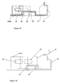
- Figure 1 (ie companion Figures 1 A and 1 B) shows a
container 10 withbase 12,roof 13 supported onlongitudinal top rails 14, andintermediate headers 15,front end frame 16,rear end frame 17 incorporating a pair ofdoors 18,floor 19 comprising typically timber boards laid on transverse steel channels 20 spanninglongitudinal bottom rails 21corner posts known corner castings 24 at top and bottom. -
Posts 22 at the front end are typically joined by a corrugatedsteel wall panel 60 closing off the front end. Intermediate of thecorner castings 24 aretop handling fittings 25, interconnected transversely byheader 15 andbottom handling fittings 26 incorporated withinbottom rails 21 and connected transversely by intermediate sill 20. -
Side openings 27 are bounded by top andbottom rails corner posts container 10 fitted with aplastics curtain 28 hanging from roller rails fixed the length oftop rails 14 and fastened to the side frame as required. In use, handlingcontainer 10 is viacorner castings 24 and/orfittings - When handling and stacking through
corner castings 24, there is direct support throughcorner posts fittings - At a 'rear' end, a stub wall 29 - fitted to one or both sides of the container - with
intermediate post 30 satisfies that end. - However, for unhindered cargo access, a side opening of maximum width is desirable - which makes use of such a
stub wall 29 at both ends undesirable. - In some ways this can be mitigated by making the
stub wall 29 short of a direct support line betweenfittings 25, 26 - as shown on the near side of the Figure 1, yet still allow a wider stub wall 29' as depicted on the other side of thecontainer 10. - In addition, at one or both ends is installed a
single post 31, connected to - or able to abut - a position onheader 15 and sill 20. - In operation, stacking loads imposed upon
fittings 25 are resisted by support fromheader 15, itself supported bypost 31. -
Post 31, if not permanently fixed to 15 header and sill 20, can be removable, or movable by sliding or hinging to allow access for cargo removal and loading when stacking is not required. - Lifting forces acting through
fittings post 31 toheader 15 and sill 20 via pins, hinges, or other connections able to generate tension in thepost 31. - Alternatively,
header 15 and sill 20 might be supported bytop rail 14 and/orbottom rail 21, either fully or in part load-sharing withintermediate post 31. Lifting forces upon such containers are generally less than half stacking forces. Thus, where only lifting, or lighter stacking, loads are to be supported,post 31 could be removed - allowing clearer load access. -
Post 31 might not necessarily be located directly betweenheader 15 and sill 20, rather but to one side or end - with necessary structural and mechanical provision by interconnection for stacking and/or lifting forces. - Two or
more posts 31 might be fitted for added strength or for more convenient location. For example, in Figure 2posts 31 might be fitted near the underside offittings 25, and spaced apart from corner posts 22 a distance `D', to allow free movement in and out of thecontainer 10 of pallets of known width a little less than 'D' typically 1200mm and 8OOmm in Europe and 1.18m in Australia. - Alternatively, the distance' D' might apply between
post 31 andpanel 60 shown in broken line - the distance 'D' being denoted (D'). - Pallets are then withdrawn by rotation and side shifting,
past post 31, but enabling such pallets to be unloaded from either side. - A clearance 'C' denoted by arrows between
post 31 andheader 15, or top rail 14 (or sill 20 and bottom rail 21 ) could be some 10 to 30mm. Clearance 'C' is useful to accommodate movement ofpost 31 into position. - When lifting loads are applied through
top fittings 25, theheader 15 and/ortop rail 14 deflect upward untilcontainer 10 begins to be lifted clear of the ground or other support. In this mode, clearance 'C' would simply increase andtop rail 14,corner posts 22,bottom rail 21 strain until supporting the lift. - When heavier stacking loads are applied,
header 15 deflects downward andtop rail 14,corner posts 22 andbottom rail 21 would not be strong enough to take those heavier loads in full. However, they do strain to take a substantial part of the stacking load, until the clearance 'C' is taken up and thenpost 31 comes into play. - By careful construction and design,
post 31 can be relieved of up to 50% of the stacking load and thus be conveniently of lighter weight construction than otherwise. - An alternative to lifting loads being carried by
fixed structure - A
spigot 32 is fixed to therail 14 viaplate 33. Ahole plate 34 is fixed to post 21 withhole 35 slotted to provide clearance above and/or below thespigot 32, of theorder 10 to 20mm. making opening and closing or movement of thepost 31 easier. - Under lifting or stacking loads through fitting 25, the clearance is taken up and the resultant deflections of the fixed frame perform as already described - with the potential of sharing these loads through post 31 and fixed
structure - An alternative to the spigot might be the use of conventional container door locking bars.
- In Figure 4,
post 31 is hinged to sill and header - (the following arrangements being illustrated at the post top and largely mirrored yet adapted at the bottom sill) - ahinge pin 36 might be offset on anarm 37 or cantilevered as shown in Figure 4 from a stacking abutment 38 - in this example part of alongitudinal beam 39 spanningfront end header 40* andintermediate header 25/45*. -
Post 31 can be moved from a stacking position aboutaxis 41 ofhinge pin 36 clear of cargo movements when required - In another embodiment of Figure 5,
post 31 might comprise a solid panel hinged to allow it to be positioned in alternative locations allowing free movement ofpallets 42 in the transverse direction and maximising width (space) for longer cargo, such as 12m pipes to be loaded through the sides, withpost 31 turned to position 31'. - Within container storage depots, handling of containers can be by a
side frame 43 mounted on afork lift truck 44, which engages thefittings 25 through known twist-locks 47. To be able to lift from one side ofcontainer 10, handlingframe 43 requires anabutment 46 near thebase 12 of the container. - On closed containers abutment 46 can be made more or less anywhere upon the surface of their side walls. But on curtain or open sided containers additional structure is provided to solve the problem. Thus Figure 6 shows such a frame and an abutment surface formed by
abutment plate 48 fixed to thebottom side rail 21. - When fitted,
side curtain 28 is shown in section line coming down past the level offloor 19 and being tucked in behindabutment plate 48, for protection from puncture by handlingframe abutment 46. Ifpost 31 is fitted close enough underfittings 25, andcurtain 18 is taken behind,post 31 can itself serve as such an abutment surface. - In Figure 4 the
top rail 15 can be reinforced by adiagonal bracing struts 54 back tocorner posts 22 to assist in the structural requirements of lifting and stacking, whilst bearing in mind that flexibility of the structure must be matched with clearance 'C'. -
Strut 54 might be pin-jointed totop rail 15 andcorner post 22 as illustrated (and thus be (re)movable to position 54' for cargo access, or be fixed permanently. Figure 1 shows in the rear far side stub wall a 'letter box' opening 58, to allow insertion of fork truck tines under a pallet (not shown), sited adjacent to the stub wall. - The tines can then be used to side shift the pallet to a new position on the
floor 19 without need to remove the wall. In Figure 5, post 31 can be of chosen section - either slim or bulky according to geometric space requirements of cargo. - In Figure 4
hinge 46 might be mounted not onheader 15 and sill 20, but on some other location to suit cargo and operating needs. - Figure 7 is a section through post 22 - with the location of
fittings aperture 40** shown. -
Post 22/52* comprises one or more pressings to form a composite structure terminating at the front face withend panel 51 and at the side areinforcement 52 located underneath fitting 25. - Fitting 25 might be extended, as shown in broken line, to allow a longer aperture 40'** to be formed in it, to aid cleaning and location of handling devices and thus enable
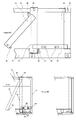
post 22 to be shortened back to 52', thereby increasing the side access dimension between end posts and/or stub walls. - Figure 8 shows a side elevation of an alternative where
post 31 is attached by apivot 55 totop rail 14 and keyed tobottom side rail 21 by aspigot 56, which engages ahole plate 57 seen in section, fixed to the side rail. Apallet 64 is depicted blocked from removal bypost 12 and post 31'. - However, engagement of
fork lift tines 58 and utilisation of side shifting ability offork tines 58 allows the post 31' to be displaced to 31, with or without apallet 64, and then be free to be withdrawnpast post 22. - Figure 9 shows a
post 31 which is inclined to the vertical. It aims to meet close totop fitting 25 and fully support a slendertop rail 14 against stacking and lifting loads, yet make use of a morerobust bottom rail 21, by cutting back to enlarge the side opening at the level offloor 19. - In this way, pallets can be side-shifted, behind the
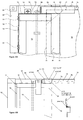
post 31, close towards an otherwise obscured end ofcontainer 10. Weather-tightness is a difficulty in curtain sided containers, especially where the curtain joins posts and top rails. - Figure 10 illustrates an improved seal arrangement.
Post 31 is formed as part of arectangular door 70, attached to post 22 at hinges 71. - To the four perimeter edges of 72 of
door 70 is fastened a double-lipped gasket 73, which seals a gap betweenclosed door 70 andtop rail 14,corner post 22 andbottom side rail 21. - Note that
side rail 75 is extended down toline 74 to come closer to the top ofdoor edge 72 and engagegasket 73. - Attached to
side rail 75 is curtain 76 - which is depicted transparent for ease of illustration - drawn overpost 31, with its perimeter in drawn position 76'. - Over
curtain 76 is shown arubber pelmet 77, fixed toside rail 75 and terminating along its bottom edge atline 79 closely level with an edge 78 ofside rail 75. - The overlap, as illustrated, of door, curtain and pelmet assists greatly in closing a potential water leak.
Post 31 abuts side rails 14, 21 as before with clearance 'C', and possible spigot keying into the rails. - A conventional door cam and keep
arrangement 84 secures the door to the side frame and can be arranged to take lifting loads throughfittings 15. - The top left hand corner of
curtain 76 might be reinforced by ablade 81* or sheet of a resilient low friction material - perhaps of a triangular shaped dense neoprene foam or rubber, so that ascurtain 76 is drawn closed - in this example to the left, it can slide easily between pelmet and door. - Figure 11 shows a similar view to Figure 6 with a
drop door 82, attached by hinges tobottom side rail 21.Door 82 is locked by some means (not shown) in a vertical position at which it serves to retain cargo within thecontainer 10.Door 82 can be released and fold outwards to allow access to the cargo space. - The danger is that, should door 82 be allowed to contact the
ground 86, andbottom rail 21 deflect downward towards theground 86 as the cargo weight bears upon it, damage would be incurred to the door 82 - as well as the inconvenience of thedoor 82 liable to jamming on the ground and not be able to be closed. - Thus a
flexible buffer 83 might be placed onbottom rail 21 to support thedoor 82 above the ground and allow flexing of thedoor 82, in the event of impact with such asfork lift truck 44. - Fig 12 shows a side elevation of
container 10 with apost 90 which is not vertical, but cranked at abend 91 toward fitting 25, for support against stacking and other handling loads.Strut 91 could connect to one side of, and/or beneath fitting 25. - In Figure 13 a post 93 is set vertical, all the way up to
top rail 14.Handling fittings 25 cannot support heavy stacking loads required of containers in a simple cantilever mounting from post 93, so asupplementary brace 95 is provided. - Overall, a open
sided container 10, withtop handling fittings 25 intermediate ends of acontainer 10 is fitted with an intermediate post dedicated to address those fittings. - Such a post set at intermediate span can be cranked to enlarge a side access aperture - at least at floor level - yet support an intermediate handling fitting.
- A post with offset strut could support an intermediate fitting set somewhat to one side of the post axis. The strut may comprise a tube, pressing, plate of up to 50 mm thick, gusset or any other frame or support.
- The post may be inclined overall to the vertical, and/or cranked once or more times from an inclined or vertical line.
- In Figure 13 a
strut 95 is welded to post 93 andfitting 25. Alternatively, it might be screwed, bolted, pinned or otherwise fixed to post 93 andfitting 25.Bolts 94 reflect an example fastening device - with the benefit that it could be removed if so required for additional cargo access under fitting 25. -
- 10
- container
- 11
- 12
- base
- 13
- roof
- 14
- top rail
- 15
- header
- 16
- front end frame
- 17
- rear end frame
- 18
- door
- 19
- floor
- 20
- transverse channels (sill)
- 21
- longitudinal bottom rail
- 22
- corner post
- 23
- corner post
- 24
- corner casting
- 25
- handling fittings (top rail)
- 26
- handling fittings (bottom rail)
- 27
- side openings
- 28
- plastics curtain
- 29
- stub wall
- 30
- intermediate post
- 31
- post
- 32
- spigot
- 33
- plate
- 34
- hole plate
- 35
- hole
- 36
- hinge pin
- 37
- arm
- 38
- abutment
- 39
- beam
- 40
- header
- 41
- hinge axis
- 42
- pallet
- 43
- side frame
- 44
- fork lift truck
- 45
- intermediate header
- 46
- abutment
- 47
- twist-lock
- 48
- abutment plate
- 51
- end panel
- 52
- reinforcement
- 54
- strut
- 55
- pivot
- 56
- spigot
- 57
- hole plate
- 58
- fork lift tines
- 59
- letter box opening
- 60
- corrugated wall panel
- 64
- pallet
- 70
- door
- 71
- hinge
- 72
- perimeter edge
- 73
- gasket
- 74
- line
- 75
- side rail
- 76
- curtain
- 77
- pelmet
- 78
- edge
- 79
- line
- 81
- blade
- 82
- drop door
- 83
- buffer
- 84
- door cam
- 86
- ground
- 90
- post
- 91
- bend
- 92
- strut
- 93
- post
- 94
- bolt
- 95
- strut
Claims (16)
- An open-sided container (10)
with handling fittings (25, 26) carried by a longitudinal top or roof rail (14) at a span intermediate corner end posts (22) and supported (from below) by an inclined post (31), strut, or brace. - A container of Claim 1,
with a support post of cranked or offset profile at an upper end, for attachment to a top rail carrying a handling fitting at a point inset from and inboard of a post lower end and from one side of and/or below a handling fitting. - A container of either preceding claim,
with a support post between top and bottom rails a lateral offshoot, strut or brace at an upper post end to a top rail and/or handling fitting carried by the top rail. - A container of any preceding claim
with a straight post between upper and lower rails fitted with a supplementary cranked or offset arm, strut or brace, to a top rail and/or handling fitting carried by a top rail. - A container of any preceding claim
with a lower end mounted upon a bottom rail and an upper end secured to a top rail, the post ends being mutually offset or displaced longitudinally, to provide differential span side access clearance at opposite ends. - A container of any preceding claim
with handling fittings set at opposite ends of a transverse header beam spanning between top rails at opposite container sides. - A container of any preceding claim
with a post pivot mounting at one end to allow inclined post orientation in relation to a top rail with handling fitting. - A container of any preceding claim with a detachable coupling
between a post upper end and a top rail and/or handling fitting. - A container of any preceding claim with a demountable post.
- A container of any preceding claim
with a post configured to take side lifting load
between an abutment at a lower end <braced by a bottom rail> and a coupling at an upper end <braced by a top rail>. - A container of any preceding claim
with a post pivoted at an upper end and a detachable coupling at its lower end, to allow an inclined post disposition. - A container of any preceding claim
with a post integrated with, or substituted by, a gate or door, with a detachable coupling with a top or bottom rail, and intervening seal with a container frame. - A container of any preceding claim
configured with a variable clearance between a post upper end and a top rail or handling fitting to accommodate rail deflection upon loading. - A container of any preceding claim
with a post movable upon or between top and bottom rails to a longitudinal span position intermediate a handling fitting and a corner end post at one or other end, to a compromise between lateral access and fitting support. - A container of any preceding claim
with a movable brace between a top rail or handling fitting and a corner end post. - A container of any preceding claim
with a multiple dog-leg, cranked, or zig-zag profile, for differential lateral access clearance and mutually offset opposite end alignment at points of connection between a top rail or handling fitting and a bottom rail.
Applications Claiming Priority (1)
| Application Number | Priority Date | Filing Date | Title |
|---|---|---|---|
| GB0425374A GB0425374D0 (en) | 2004-11-17 | 2004-11-17 | Improvements in open sided containers |
Publications (2)
| Publication Number | Publication Date |
|---|---|
| EP1659076A1 true EP1659076A1 (en) | 2006-05-24 |
| EP1659076B1 EP1659076B1 (en) | 2014-10-08 |
Family
ID=33548450
Family Applications (1)
| Application Number | Title | Priority Date | Filing Date |
|---|---|---|---|
| EP20050257114 Expired - Lifetime EP1659076B1 (en) | 2004-11-17 | 2005-11-17 | Handling & stacking support for open-sided container |
Country Status (2)
| Country | Link |
|---|---|
| EP (1) | EP1659076B1 (en) |
| GB (1) | GB0425374D0 (en) |
Cited By (9)
| Publication number | Priority date | Publication date | Assignee | Title |
|---|---|---|---|---|
| EP2088094A1 (en) | 2008-02-08 | 2009-08-12 | Zentrum für angewandte Forschung und Technologie E.V. | Loading unit for international transport and enveloping of goods |
| GB2463328A (en) * | 2008-07-24 | 2010-03-17 | Dale Botham | Collapsible curtain sided cargo container |
| DE102013002006A1 (en) * | 2013-02-06 | 2014-08-07 | CES Containerhandling Equipment & Solutions GmbH | Transport container for use on e.g. lorry for transporting goods, has vertical auxiliary support selectively brought into function position, in which support supports cover part at bottom part, and non-function position |
| CN108502384A (en) * | 2018-05-18 | 2018-09-07 | 中集车辆(集团)有限公司 | A kind of commuting case and packing method detachably transported |
| EP3552992A1 (en) * | 2018-04-09 | 2019-10-16 | Allog GmbH | Transport platform |
| TWI680095B (en) * | 2018-09-10 | 2019-12-21 | 陳文登 | Container handling structure |
| JP2020111363A (en) * | 2019-01-11 | 2020-07-27 | 株式会社総合車両製作所 | container |
| WO2022184319A1 (en) * | 2021-03-02 | 2022-09-09 | Wenker Gmbh & Co. Kg | Transport device for piece goods, and use thereof |
| DE102024130733A1 (en) * | 2024-10-22 | 2026-04-23 | Wecon GmbH Nutzfahrzeuge - Container-Technik | Large-capacity container |
Citations (8)
| Publication number | Priority date | Publication date | Assignee | Title |
|---|---|---|---|---|
| GB2337509A (en) * | 1998-05-20 | 1999-11-24 | Sea Containers Services Ltd | Freight container with detachable angled stays |
| GB2368336A (en) * | 2000-10-27 | 2002-05-01 | Adaptainer Palletwide Ltd | A freight container |
| DE10215831A1 (en) * | 2001-04-10 | 2002-11-28 | Martin Clive-Smith | Collapsible platform base container or flat rack for transporting vehicles comprises folding intermediate corner posts and outer end support frames on a platform base |
| GB2393435A (en) * | 2002-08-02 | 2004-03-31 | Martin Clive-Smith | End structures for containers |
| US6739468B1 (en) * | 1999-08-16 | 2004-05-25 | Sea Containers Services Ltd. | Freight container |
| US20040222219A1 (en) * | 2002-12-23 | 2004-11-11 | Sea Containers Services Ltd. | Freight container |
| WO2004106193A1 (en) * | 2003-05-27 | 2004-12-09 | Container Leasing Uk Limited | Freight container |
| EP1632442A1 (en) * | 2004-07-15 | 2006-03-08 | Cobra Containers S.p.A. | Curtainside container |
-
2004
- 2004-11-17 GB GB0425374A patent/GB0425374D0/en not_active Ceased
-
2005
- 2005-11-17 EP EP20050257114 patent/EP1659076B1/en not_active Expired - Lifetime
Patent Citations (8)
| Publication number | Priority date | Publication date | Assignee | Title |
|---|---|---|---|---|
| GB2337509A (en) * | 1998-05-20 | 1999-11-24 | Sea Containers Services Ltd | Freight container with detachable angled stays |
| US6739468B1 (en) * | 1999-08-16 | 2004-05-25 | Sea Containers Services Ltd. | Freight container |
| GB2368336A (en) * | 2000-10-27 | 2002-05-01 | Adaptainer Palletwide Ltd | A freight container |
| DE10215831A1 (en) * | 2001-04-10 | 2002-11-28 | Martin Clive-Smith | Collapsible platform base container or flat rack for transporting vehicles comprises folding intermediate corner posts and outer end support frames on a platform base |
| GB2393435A (en) * | 2002-08-02 | 2004-03-31 | Martin Clive-Smith | End structures for containers |
| US20040222219A1 (en) * | 2002-12-23 | 2004-11-11 | Sea Containers Services Ltd. | Freight container |
| WO2004106193A1 (en) * | 2003-05-27 | 2004-12-09 | Container Leasing Uk Limited | Freight container |
| EP1632442A1 (en) * | 2004-07-15 | 2006-03-08 | Cobra Containers S.p.A. | Curtainside container |
Cited By (11)
| Publication number | Priority date | Publication date | Assignee | Title |
|---|---|---|---|---|
| EP2088094A1 (en) | 2008-02-08 | 2009-08-12 | Zentrum für angewandte Forschung und Technologie E.V. | Loading unit for international transport and enveloping of goods |
| DE102008009131A1 (en) * | 2008-02-08 | 2009-08-20 | Cideon Engineering Gmbh | Loading unit for intermodal transport and handling of goods |
| GB2463328A (en) * | 2008-07-24 | 2010-03-17 | Dale Botham | Collapsible curtain sided cargo container |
| DE102013002006A1 (en) * | 2013-02-06 | 2014-08-07 | CES Containerhandling Equipment & Solutions GmbH | Transport container for use on e.g. lorry for transporting goods, has vertical auxiliary support selectively brought into function position, in which support supports cover part at bottom part, and non-function position |
| EP3552992A1 (en) * | 2018-04-09 | 2019-10-16 | Allog GmbH | Transport platform |
| CN108502384A (en) * | 2018-05-18 | 2018-09-07 | 中集车辆(集团)有限公司 | A kind of commuting case and packing method detachably transported |
| CN108502384B (en) * | 2018-05-18 | 2024-05-24 | 中集车辆(集团)股份有限公司 | Detachable transport exchange box and boxing method |
| TWI680095B (en) * | 2018-09-10 | 2019-12-21 | 陳文登 | Container handling structure |
| JP2020111363A (en) * | 2019-01-11 | 2020-07-27 | 株式会社総合車両製作所 | container |
| WO2022184319A1 (en) * | 2021-03-02 | 2022-09-09 | Wenker Gmbh & Co. Kg | Transport device for piece goods, and use thereof |
| DE102024130733A1 (en) * | 2024-10-22 | 2026-04-23 | Wecon GmbH Nutzfahrzeuge - Container-Technik | Large-capacity container |
Also Published As
| Publication number | Publication date |
|---|---|
| GB0425374D0 (en) | 2004-12-22 |
| EP1659076B1 (en) | 2014-10-08 |
Similar Documents
| Publication | Publication Date | Title |
|---|---|---|
| EP1567429B1 (en) | Collapsible flat rack | |
| EP2389328B1 (en) | Base frame / end cover engagement assembly for a collapsible container | |
| US6109469A (en) | Freight container | |
| EP1659076B1 (en) | Handling & stacking support for open-sided container | |
| EP2686252B1 (en) | Freight container | |
| US8876217B1 (en) | Cover assembly for open top container | |
| AU756429B2 (en) | Vehicle side tipper system | |
| EP3601105B1 (en) | A collapsible intermodal container and a collapsible intermodal container assembly | |
| FI121746B (en) | locking arrangements | |
| US20040222219A1 (en) | Freight container | |
| US2932262A (en) | Reinforcing structures for temporary barricades for doors of boxcars and grain cars | |
| GB2393435A (en) | End structures for containers | |
| GB2368336A (en) | A freight container | |
| FR2710019A1 (en) | Box body with lift-up sidewalls for road-transport vehicle and vehicle equipped with such a box body | |
| CN111469876B (en) | A reinforced freight train car roof | |
| EP0881112A1 (en) | Integrated system for large-volume containers and transport means | |
| RU224451U1 (en) | LARGE-CAPACITY CARGO BODY FOR TRANSPORTATION OF PIECE, BULK AND BULK DRY CARGO | |
| CA2799271C (en) | Convertible trailer | |
| AU2006100271B4 (en) | Trailer support posts | |
| AU2004100514B4 (en) | Improved freight container | |
| HK1188195B (en) | Freight container | |
| GB2288791A (en) | Shipping container | |
| ZA200103983B (en) | Vehicle side tipper system. | |
| HK40020488B (en) | A collapsible intermodal container and a collapsible intermodal container assembly | |
| HK40020488A (en) | A collapsible intermodal container and a collapsible intermodal container assembly |
Legal Events
| Date | Code | Title | Description |
|---|---|---|---|
| PUAI | Public reference made under article 153(3) epc to a published international application that has entered the european phase |
Free format text: ORIGINAL CODE: 0009012 |
|
| AK | Designated contracting states |
Kind code of ref document: A1 Designated state(s): AT BE BG CH CY CZ DE DK EE ES FI FR GB GR HU IE IS IT LI LT LU LV MC NL PL PT RO SE SI SK TR |
|
| AX | Request for extension of the european patent |
Extension state: AL BA HR MK YU |
|
| 17P | Request for examination filed |
Effective date: 20061124 |
|
| AKX | Designation fees paid |
Designated state(s): AT BE BG CH CY CZ DE DK EE ES FI FR GB GR HU IE IS IT LI LT LU LV MC NL PL PT RO SE SI SK TR |
|
| 17Q | First examination report despatched |
Effective date: 20070130 |
|
| 18D | Application deemed to be withdrawn |
Effective date: 20120828 |
|
| D18D | Application deemed to be withdrawn (deleted) | ||
| GRAP | Despatch of communication of intention to grant a patent |
Free format text: ORIGINAL CODE: EPIDOSNIGR1 |
|
| RAP1 | Party data changed (applicant data changed or rights of an application transferred) |
Owner name: BOTHAM, DALE Owner name: SMITH, CLIVE-SMITH |
|
| RIN1 | Information on inventor provided before grant (corrected) |
Inventor name: BOTHAM, DALE Inventor name: SMITH, CLIVE-SMITH |
|
| INTG | Intention to grant announced |
Effective date: 20140619 |
|
| RAP1 | Party data changed (applicant data changed or rights of an application transferred) |
Owner name: ICON CONTAINERS LIMITED |
|
| RIN1 | Information on inventor provided before grant (corrected) |
Inventor name: BOTHAM, DALE Inventor name: CLIVE-SMITH, MARTIN |
|
| GRAS | Grant fee paid |
Free format text: ORIGINAL CODE: EPIDOSNIGR3 |
|
| GRAA | (expected) grant |
Free format text: ORIGINAL CODE: 0009210 |
|
| AK | Designated contracting states |
Kind code of ref document: B1 Designated state(s): AT BE BG CH CY CZ DE DK EE ES FI FR GB GR HU IE IS IT LI LT LU LV MC NL PL PT RO SE SI SK TR |
|
| REG | Reference to a national code |
Ref country code: AT Ref legal event code: REF Ref document number: 690440 Country of ref document: AT Kind code of ref document: T Effective date: 20141015 Ref country code: CH Ref legal event code: EP |
|
| REG | Reference to a national code |
Ref country code: IE Ref legal event code: FG4D |
|
| REG | Reference to a national code |
Ref country code: DE Ref legal event code: R096 Ref document number: 602005044860 Country of ref document: DE Effective date: 20141120 |
|
| PGFP | Annual fee paid to national office [announced via postgrant information from national office to epo] |
Ref country code: DK Payment date: 20141111 Year of fee payment: 10 |
|
| REG | Reference to a national code |
Ref country code: NL Ref legal event code: T3 |
|
| PGFP | Annual fee paid to national office [announced via postgrant information from national office to epo] |
Ref country code: CH Payment date: 20141112 Year of fee payment: 10 Ref country code: ES Payment date: 20141028 Year of fee payment: 10 Ref country code: IE Payment date: 20141110 Year of fee payment: 10 Ref country code: LU Payment date: 20141202 Year of fee payment: 10 |
|
| PGFP | Annual fee paid to national office [announced via postgrant information from national office to epo] |
Ref country code: AT Payment date: 20141027 Year of fee payment: 10 |
|
| REG | Reference to a national code |
Ref country code: AT Ref legal event code: MK05 Ref document number: 690440 Country of ref document: AT Kind code of ref document: T Effective date: 20141008 |
|
| REG | Reference to a national code |
Ref country code: LT Ref legal event code: MG4D |
|
| PG25 | Lapsed in a contracting state [announced via postgrant information from national office to epo] |
Ref country code: IS Free format text: LAPSE BECAUSE OF FAILURE TO SUBMIT A TRANSLATION OF THE DESCRIPTION OR TO PAY THE FEE WITHIN THE PRESCRIBED TIME-LIMIT Effective date: 20150208 Ref country code: LT Free format text: LAPSE BECAUSE OF FAILURE TO SUBMIT A TRANSLATION OF THE DESCRIPTION OR TO PAY THE FEE WITHIN THE PRESCRIBED TIME-LIMIT Effective date: 20141008 Ref country code: ES Free format text: LAPSE BECAUSE OF FAILURE TO SUBMIT A TRANSLATION OF THE DESCRIPTION OR TO PAY THE FEE WITHIN THE PRESCRIBED TIME-LIMIT Effective date: 20141008 Ref country code: FI Free format text: LAPSE BECAUSE OF FAILURE TO SUBMIT A TRANSLATION OF THE DESCRIPTION OR TO PAY THE FEE WITHIN THE PRESCRIBED TIME-LIMIT Effective date: 20141008 Ref country code: PT Free format text: LAPSE BECAUSE OF FAILURE TO SUBMIT A TRANSLATION OF THE DESCRIPTION OR TO PAY THE FEE WITHIN THE PRESCRIBED TIME-LIMIT Effective date: 20150209 |
|
| PG25 | Lapsed in a contracting state [announced via postgrant information from national office to epo] |
Ref country code: CY Free format text: LAPSE BECAUSE OF FAILURE TO SUBMIT A TRANSLATION OF THE DESCRIPTION OR TO PAY THE FEE WITHIN THE PRESCRIBED TIME-LIMIT Effective date: 20141008 Ref country code: GR Free format text: LAPSE BECAUSE OF FAILURE TO SUBMIT A TRANSLATION OF THE DESCRIPTION OR TO PAY THE FEE WITHIN THE PRESCRIBED TIME-LIMIT Effective date: 20150109 Ref country code: LV Free format text: LAPSE BECAUSE OF FAILURE TO SUBMIT A TRANSLATION OF THE DESCRIPTION OR TO PAY THE FEE WITHIN THE PRESCRIBED TIME-LIMIT Effective date: 20141008 Ref country code: SE Free format text: LAPSE BECAUSE OF FAILURE TO SUBMIT A TRANSLATION OF THE DESCRIPTION OR TO PAY THE FEE WITHIN THE PRESCRIBED TIME-LIMIT Effective date: 20141008 Ref country code: PL Free format text: LAPSE BECAUSE OF FAILURE TO SUBMIT A TRANSLATION OF THE DESCRIPTION OR TO PAY THE FEE WITHIN THE PRESCRIBED TIME-LIMIT Effective date: 20141008 |
|
| REG | Reference to a national code |
Ref country code: DE Ref legal event code: R097 Ref document number: 602005044860 Country of ref document: DE |
|
| PG25 | Lapsed in a contracting state [announced via postgrant information from national office to epo] |
Ref country code: RO Free format text: LAPSE BECAUSE OF FAILURE TO SUBMIT A TRANSLATION OF THE DESCRIPTION OR TO PAY THE FEE WITHIN THE PRESCRIBED TIME-LIMIT Effective date: 20141008 Ref country code: DK Free format text: LAPSE BECAUSE OF FAILURE TO SUBMIT A TRANSLATION OF THE DESCRIPTION OR TO PAY THE FEE WITHIN THE PRESCRIBED TIME-LIMIT Effective date: 20141008 Ref country code: SK Free format text: LAPSE BECAUSE OF FAILURE TO SUBMIT A TRANSLATION OF THE DESCRIPTION OR TO PAY THE FEE WITHIN THE PRESCRIBED TIME-LIMIT Effective date: 20141008 Ref country code: CZ Free format text: LAPSE BECAUSE OF FAILURE TO SUBMIT A TRANSLATION OF THE DESCRIPTION OR TO PAY THE FEE WITHIN THE PRESCRIBED TIME-LIMIT Effective date: 20141008 Ref country code: EE Free format text: LAPSE BECAUSE OF FAILURE TO SUBMIT A TRANSLATION OF THE DESCRIPTION OR TO PAY THE FEE WITHIN THE PRESCRIBED TIME-LIMIT Effective date: 20141008 |
|
| PLBE | No opposition filed within time limit |
Free format text: ORIGINAL CODE: 0009261 |
|
| STAA | Information on the status of an ep patent application or granted ep patent |
Free format text: STATUS: NO OPPOSITION FILED WITHIN TIME LIMIT |
|
| PG25 | Lapsed in a contracting state [announced via postgrant information from national office to epo] |
Ref country code: IT Free format text: LAPSE BECAUSE OF FAILURE TO SUBMIT A TRANSLATION OF THE DESCRIPTION OR TO PAY THE FEE WITHIN THE PRESCRIBED TIME-LIMIT Effective date: 20141008 |
|
| 26N | No opposition filed |
Effective date: 20150709 |
|
| REG | Reference to a national code |
Ref country code: FR Ref legal event code: PLFP Year of fee payment: 11 |
|
| PGFP | Annual fee paid to national office [announced via postgrant information from national office to epo] |
Ref country code: MC Payment date: 20150930 Year of fee payment: 11 |
|
| PG25 | Lapsed in a contracting state [announced via postgrant information from national office to epo] |
Ref country code: SI Free format text: LAPSE BECAUSE OF FAILURE TO SUBMIT A TRANSLATION OF THE DESCRIPTION OR TO PAY THE FEE WITHIN THE PRESCRIBED TIME-LIMIT Effective date: 20141008 |
|
| PGFP | Annual fee paid to national office [announced via postgrant information from national office to epo] |
Ref country code: BE Payment date: 20151123 Year of fee payment: 11 |
|
| PG25 | Lapsed in a contracting state [announced via postgrant information from national office to epo] |
Ref country code: BG Free format text: LAPSE BECAUSE OF FAILURE TO SUBMIT A TRANSLATION OF THE DESCRIPTION OR TO PAY THE FEE WITHIN THE PRESCRIBED TIME-LIMIT Effective date: 20141008 |
|
| PG25 | Lapsed in a contracting state [announced via postgrant information from national office to epo] |
Ref country code: LU Free format text: LAPSE BECAUSE OF NON-PAYMENT OF DUE FEES Effective date: 20151117 |
|
| REG | Reference to a national code |
Ref country code: CH Ref legal event code: PL |
|
| PG25 | Lapsed in a contracting state [announced via postgrant information from national office to epo] |
Ref country code: HU Free format text: LAPSE BECAUSE OF FAILURE TO SUBMIT A TRANSLATION OF THE DESCRIPTION OR TO PAY THE FEE WITHIN THE PRESCRIBED TIME-LIMIT; INVALID AB INITIO Effective date: 20051117 Ref country code: LI Free format text: LAPSE BECAUSE OF NON-PAYMENT OF DUE FEES Effective date: 20151130 Ref country code: CH Free format text: LAPSE BECAUSE OF NON-PAYMENT OF DUE FEES Effective date: 20151130 Ref country code: TR Free format text: LAPSE BECAUSE OF FAILURE TO SUBMIT A TRANSLATION OF THE DESCRIPTION OR TO PAY THE FEE WITHIN THE PRESCRIBED TIME-LIMIT Effective date: 20141008 |
|
| REG | Reference to a national code |
Ref country code: IE Ref legal event code: MM4A |
|
| PG25 | Lapsed in a contracting state [announced via postgrant information from national office to epo] |
Ref country code: AT Free format text: THE PATENT HAS BEEN ANNULLED BY A DECISION OF A NATIONAL AUTHORITY Effective date: 20141008 |
|
| REG | Reference to a national code |
Ref country code: FR Ref legal event code: PLFP Year of fee payment: 12 |
|
| PG25 | Lapsed in a contracting state [announced via postgrant information from national office to epo] |
Ref country code: IE Free format text: LAPSE BECAUSE OF NON-PAYMENT OF DUE FEES Effective date: 20151117 |
|
| REG | Reference to a national code |
Ref country code: FR Ref legal event code: PLFP Year of fee payment: 13 |
|
| PG25 | Lapsed in a contracting state [announced via postgrant information from national office to epo] |
Ref country code: MC Free format text: LAPSE BECAUSE OF NON-PAYMENT OF DUE FEES Effective date: 20161130 Ref country code: BE Free format text: LAPSE BECAUSE OF NON-PAYMENT OF DUE FEES Effective date: 20161130 |
|
| REG | Reference to a national code |
Ref country code: FR Ref legal event code: PLFP Year of fee payment: 14 |
|
| PG25 | Lapsed in a contracting state [announced via postgrant information from national office to epo] |
Ref country code: ES Free format text: THE PATENT HAS BEEN ANNULLED BY A DECISION OF A NATIONAL AUTHORITY Effective date: 20141008 |
|
| PGFP | Annual fee paid to national office [announced via postgrant information from national office to epo] |
Ref country code: GB Payment date: 20230928 Year of fee payment: 19 |
|
| PGFP | Annual fee paid to national office [announced via postgrant information from national office to epo] |
Ref country code: NL Payment date: 20231016 Year of fee payment: 19 Ref country code: FR Payment date: 20230911 Year of fee payment: 19 |
|
| PGFP | Annual fee paid to national office [announced via postgrant information from national office to epo] |
Ref country code: DE Payment date: 20230919 Year of fee payment: 19 |
|
| REG | Reference to a national code |
Ref country code: DE Ref legal event code: R119 Ref document number: 602005044860 Country of ref document: DE |
|
| REG | Reference to a national code |
Ref country code: NL Ref legal event code: MM Effective date: 20241201 |
|
| GBPC | Gb: european patent ceased through non-payment of renewal fee |
Effective date: 20241117 |
|
| PG25 | Lapsed in a contracting state [announced via postgrant information from national office to epo] |
Ref country code: NL Free format text: LAPSE BECAUSE OF NON-PAYMENT OF DUE FEES Effective date: 20241201 |
|
| PG25 | Lapsed in a contracting state [announced via postgrant information from national office to epo] |
Ref country code: DE Free format text: LAPSE BECAUSE OF NON-PAYMENT OF DUE FEES Effective date: 20250603 |
|
| PG25 | Lapsed in a contracting state [announced via postgrant information from national office to epo] |
Ref country code: GB Free format text: LAPSE BECAUSE OF NON-PAYMENT OF DUE FEES Effective date: 20241117 |
|
| PG25 | Lapsed in a contracting state [announced via postgrant information from national office to epo] |
Ref country code: FR Free format text: LAPSE BECAUSE OF NON-PAYMENT OF DUE FEES Effective date: 20241130 |