EP1659263A2 - Cooling system for a gas turbine airfoil - Google Patents
Cooling system for a gas turbine airfoil Download PDFInfo
- Publication number
- EP1659263A2 EP1659263A2 EP05257023A EP05257023A EP1659263A2 EP 1659263 A2 EP1659263 A2 EP 1659263A2 EP 05257023 A EP05257023 A EP 05257023A EP 05257023 A EP05257023 A EP 05257023A EP 1659263 A2 EP1659263 A2 EP 1659263A2
- Authority
- EP
- European Patent Office
- Prior art keywords
- airfoil
- cooling
- tip cap
- tip
- cooling circuit
- Prior art date
- Legal status (The legal status is an assumption and is not a legal conclusion. Google has not performed a legal analysis and makes no representation as to the accuracy of the status listed.)
- Granted
Links
Images


Classifications
-
- F—MECHANICAL ENGINEERING; LIGHTING; HEATING; WEAPONS; BLASTING
- F01—MACHINES OR ENGINES IN GENERAL; ENGINE PLANTS IN GENERAL; STEAM ENGINES
- F01D—NON-POSITIVE DISPLACEMENT MACHINES OR ENGINES, e.g. STEAM TURBINES
- F01D5/00—Blades; Blade-carrying members; Heating, heat-insulating, cooling or antivibration means on the blades or the members
- F01D5/12—Blades
- F01D5/14—Form or construction
- F01D5/18—Hollow blades, i.e. blades with cooling or heating channels or cavities; Heating, heat-insulating or cooling means on blades
- F01D5/187—Convection cooling
- F01D5/188—Convection cooling with an insert in the blade cavity to guide the cooling fluid, e.g. forming a separation wall
-
- F—MECHANICAL ENGINEERING; LIGHTING; HEATING; WEAPONS; BLASTING
- F01—MACHINES OR ENGINES IN GENERAL; ENGINE PLANTS IN GENERAL; STEAM ENGINES
- F01D—NON-POSITIVE DISPLACEMENT MACHINES OR ENGINES, e.g. STEAM TURBINES
- F01D5/00—Blades; Blade-carrying members; Heating, heat-insulating, cooling or antivibration means on the blades or the members
- F01D5/12—Blades
- F01D5/14—Form or construction
- F01D5/18—Hollow blades, i.e. blades with cooling or heating channels or cavities; Heating, heat-insulating or cooling means on blades
-
- F—MECHANICAL ENGINEERING; LIGHTING; HEATING; WEAPONS; BLASTING
- F01—MACHINES OR ENGINES IN GENERAL; ENGINE PLANTS IN GENERAL; STEAM ENGINES
- F01D—NON-POSITIVE DISPLACEMENT MACHINES OR ENGINES, e.g. STEAM TURBINES
- F01D5/00—Blades; Blade-carrying members; Heating, heat-insulating, cooling or antivibration means on the blades or the members
- F01D5/12—Blades
- F01D5/28—Selecting particular materials; Particular measures relating thereto; Measures against erosion or corrosion
- F01D5/288—Protective coatings for blades
-
- Y—GENERAL TAGGING OF NEW TECHNOLOGICAL DEVELOPMENTS; GENERAL TAGGING OF CROSS-SECTIONAL TECHNOLOGIES SPANNING OVER SEVERAL SECTIONS OF THE IPC; TECHNICAL SUBJECTS COVERED BY FORMER USPC CROSS-REFERENCE ART COLLECTIONS [XRACs] AND DIGESTS
- Y02—TECHNOLOGIES OR APPLICATIONS FOR MITIGATION OR ADAPTATION AGAINST CLIMATE CHANGE
- Y02T—CLIMATE CHANGE MITIGATION TECHNOLOGIES RELATED TO TRANSPORTATION
- Y02T50/00—Aeronautics or air transport
- Y02T50/60—Efficient propulsion technologies, e.g. for aircraft
Definitions
- the present invention relates to a bucket for a turbine and particularly relates to a cooling system for an airfoil, and specifically the airfoil tip.
- a bucket for a gas turbine having an airfoil, a shank and a platform between the shank and the airfoil.
- the airfoil includes a cooling circuit having a plurality of passages for flowing a cooling medium within the airfoil and at least one rib extending between opposite sides of the airfoil dividing the cooling circuit into a forward cooling circuit and an aft cooling circuit.
- the airfoil also includes an airfoil tip having an opening and a tip cap secured to the airfoil closing the opening.
- the rib includes a hole for flowing a portion of the cooling medium toward the tip cap to impingement cool the tip cap.
- a bucket for a gas turbine having an airfoil, a shank and a platform between the shank and the airfoil, the airfoil including a cooling circuit having a plurality of passages for flowing a cooling medium within the airfoil.
- the airfoil includes a tip having an opening and a tip cap secured to the airfoil closing the opening.
- the tip cap has a thermal barrier coating along an outside surface thereof.
- the airfoil has a seat adjacent the airfoil tip for receiving the tip cap and which seat also has a thermal barrier coating.
- a bucket for a gas turbine rotor, not shown, including an airfoil 12, a shank 14 and a platform 16 between the shank 14 and the airfoil 12.
- the bucket 12 includes a cooling circuit, generally designated 20, having a plurality of passages for flowing a cooling medium, for example, air, within the airfoil.
- cooling air for example, compressor discharge air
- the cooling circuit 20 including a forward cooling circuit 22 and an aft cooling circuit 24.
- Inlets 26 and 28, respectively, adjacent the base of the shank 14 each provide a pair of inlet ports as illustrated for flowing a cooling medium, preferably compressor discharge air, into the respective forward and aft cooling circuits 22 and 24.
- the forward cooling circuit 22 includes a plurality of generally serpentine configured passages formed by ribs 30 and 32 and in part by a central rib 34, the ribs extending between opposite sides of the airfoil.
- the cooling medium e.g., compressor discharge air
- a supplemental passageway 40 also supplies the cooling medium directly to the leading edge film cooling holes 39.
- the aft cooling circuit 24 includes a pair of ribs 42 and 44 extending between opposite sides of the airfoil.
- the cooling medium flows through the inlet 28 in a generally radially outward direction through passage 46 between the central rib 34 and rib 42, reverses direction adjacent the tip of the airfoil for flow through passage 48 in a generally radially inward direction and finally flows in a radially outward direction via passage 50 between rib 44 and the trailing edge.
- a wall, not shown, in passage 50 and along the trailing edge, contains perforations for flowing the cooling medium through trailing edge cooling holes 52 ( Figure 3).
- the airfoil tip is provided with an opening 56 defined by a recessed seat 58.
- a tip cap 60 ( Figure 4) is disposed in the opening 56 on seat 58.
- the tip cap 60 is suitably secured to the airfoil tip on seat 58 closing the opening 56.
- Tip cap 60 may, however, have small openings therethrough to discharge a small portion of the cooling medium into the hot gas path, e.g., to exhaust particulate matter into the hot gas path.
- the radially outer face of tip cap 60 is provided with a vacuum plasma spray bond coat and a thermal barrier coating (TBC) 62.
- the bond coat and the thermal barrier coating may comprise an oxidation resistant alloy such as MCrALY and zirconia partially stabilized with yittria, respectively, as set forth in U.S. Patent No. 6,730,413, the subject matter of which is incorporated herein by reference. Other types of bond and TBC coatings may be used.
- the seat 58 i.e., the margin of the opening 56, is likewise provided with the bond coat and thermal barrier coating. These layers protect the tip cap from the elevated temperatures of the hot gas flowing in the gas path.
- the cooling circuit 20 hereof provides for active cooling of the underside of the tip cap 60. Particularly, cooling air is bled from the forward circuit for flow through a hole for impingement cooling of the tip cap 60.
- the central rib 34 is provided with a hole 70 adjacent the airfoil tip and immediately below the tip cap 60.
- the hole 70 is angled in a radially outward direction toward the aft portion of the tip cap.
- the aft portion of the tip cap constitutes the hottest portion of the tip cap.
- a jet of impingement cooling air from the forward cooling circuit 22 is directed through hole 70 onto the underside of the aft portion of the tip cap 60.
- a pressure drop is created in the aft coating circuit 24 with respect to the forward cooling circuit 22 such that the impingement hole 70 through rib 34 separating the forward and aft cooling flow circuits has sufficient jet potential to effect impingement cooling of the tip cap 60.
- Metering plates, not shown, used in the inlets 26 and 28 are also sized such that total bucket cooling flow remains the same as in prior designs while simultaneously more cooling air is directed to the aft cooling circuit. Consequently, the combined cooling effect of the impingement jet cooling flow through hole 70 together with the TBC coating 62 on the external surface of the tip cap 60 and the seat 58 for the tip cap 60, reduces both the tip cap metal temperature and thermally induced stress.
Landscapes
- Engineering & Computer Science (AREA)
- Mechanical Engineering (AREA)
- General Engineering & Computer Science (AREA)
- Chemical & Material Sciences (AREA)
- Materials Engineering (AREA)
- Turbine Rotor Nozzle Sealing (AREA)
Abstract
Description
- The present invention relates to a bucket for a turbine and particularly relates to a cooling system for an airfoil, and specifically the airfoil tip.
- With increased gas firing temperatures in modern day gas turbines, various portions along the hot gas path of the turbine are exposed to a higher heat load environment. One area that has exhibited marked increase in heat load is the tip of the airfoil on the gas turbine rotor. Excessive heat loads have resulted in airfoil tip cap oxidation and creep distress. While thicker and different materials less subject to oxidation and creep properties have been substituted for prior airfoil tip cap designs, it has been demonstrated that unacceptable tip cap stress levels may increase notwithstanding these thicker and different materials. Accordingly, there is a demonstrated need for a cooling system for the airfoil tip cap of a turbine bucket which will lower the tip cap metal temperature and thermally-induced stresses and particularly without increasing the total turbine cooling flow.
- In a preferred embodiment of the present invention, there is provided a bucket for a gas turbine having an airfoil, a shank and a platform between the shank and the airfoil. The airfoil includes a cooling circuit having a plurality of passages for flowing a cooling medium within the airfoil and at least one rib extending between opposite sides of the airfoil dividing the cooling circuit into a forward cooling circuit and an aft cooling circuit. The airfoil also includes an airfoil tip having an opening and a tip cap secured to the airfoil closing the opening. The rib includes a hole for flowing a portion of the cooling medium toward the tip cap to impingement cool the tip cap.
- In a further preferred embodiment of the invention, there is provided a bucket for a gas turbine having an airfoil, a shank and a platform between the shank and the airfoil, the airfoil including a cooling circuit having a plurality of passages for flowing a cooling medium within the airfoil. The airfoil includes a tip having an opening and a tip cap secured to the airfoil closing the opening. The tip cap has a thermal barrier coating along an outside surface thereof.
- Preferably, the airfoil has a seat adjacent the airfoil tip for receiving the tip cap and which seat also has a thermal barrier coating.
- The invention will now be described in greater detail, by way of example, with reference to the drawings, in which:-
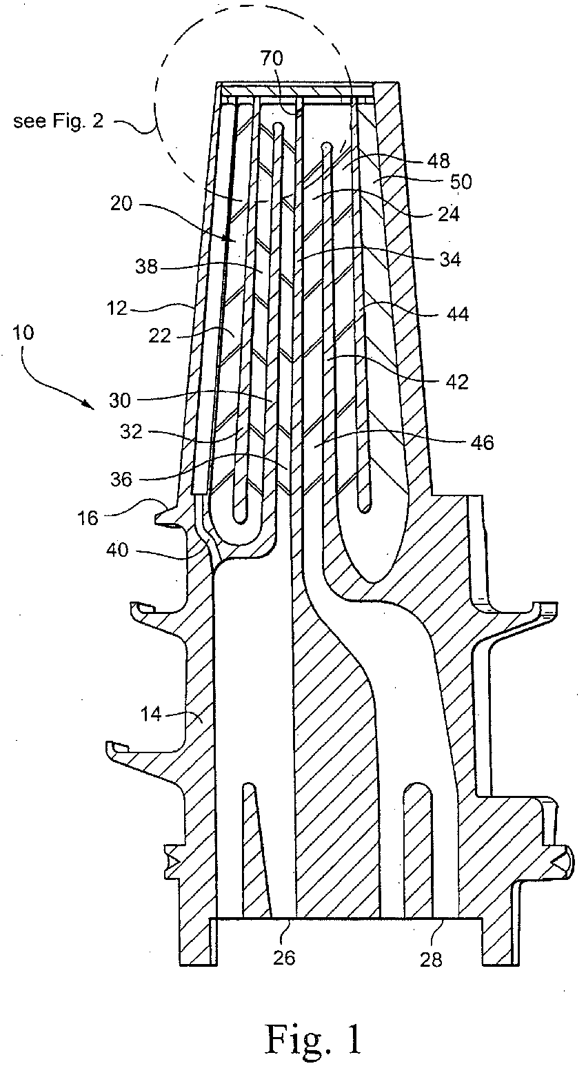
- FIGURE 1 is a schematic cross-sectional view of a bucket for a gas turbine illustrating a cooling system therefor in accordance with a preferred aspect of the present invention;
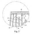
- FIGURE 2 is an enlarged cross-sectional view of a tip portion of the airfoil of Figure 1;
- FIGURE 3 is an end view of the airfoil looking generally radially inwardly; and
- FIGURE 4 is a fragmentary perspective view of a tip cap installed on the tip of the airfoil.
- Referring now to Figure 1, there is illustrated a bucket, generally designated 10, for a gas turbine rotor, not shown, including an
airfoil 12, ashank 14 and aplatform 16 between theshank 14 and theairfoil 12. As illustrated in Figure 1, thebucket 12 includes a cooling circuit, generally designated 20, having a plurality of passages for flowing a cooling medium, for example, air, within the airfoil. Particularly, it will be appreciated that cooling air, for example, compressor discharge air, may be supplied to theairfoil cooling circuit 20, thecooling circuit 20 including aforward cooling circuit 22 and anaft cooling circuit 24.Inlets shank 14 each provide a pair of inlet ports as illustrated for flowing a cooling medium, preferably compressor discharge air, into the respective forward andaft cooling circuits - The
forward cooling circuit 22 includes a plurality of generally serpentine configured passages formed byribs central rib 34, the ribs extending between opposite sides of the airfoil. Thus, the cooling medium, e.g., compressor discharge air, flows throughinlet 26 intopassage 36 in a generally radially outward direction betweenribs passage 38 betweenribs supplemental passageway 40 also supplies the cooling medium directly to the leading edgefilm cooling holes 39. - The
aft cooling circuit 24 includes a pair ofribs inlet 28 in a generally radially outward direction throughpassage 46 between thecentral rib 34 andrib 42, reverses direction adjacent the tip of the airfoil for flow throughpassage 48 in a generally radially inward direction and finally flows in a radially outward direction viapassage 50 betweenrib 44 and the trailing edge. A wall, not shown, inpassage 50 and along the trailing edge, contains perforations for flowing the cooling medium through trailing edge cooling holes 52 (Figure 3). - Referring to Figure 3, the airfoil tip is provided with an
opening 56 defined by arecessed seat 58. A tip cap 60 (Figure 4) is disposed in theopening 56 onseat 58. Thetip cap 60 is suitably secured to the airfoil tip onseat 58 closing theopening 56.Tip cap 60 may, however, have small openings therethrough to discharge a small portion of the cooling medium into the hot gas path, e.g., to exhaust particulate matter into the hot gas path. As noted previously, it is desirable to lower the tip cap metal temperature and thermally induced stresses in the tip cap without drawing off additional cooling air from the total engine flow. - To in part achieve that objective, the radially outer face of
tip cap 60 is provided with a vacuum plasma spray bond coat and a thermal barrier coating (TBC) 62. The bond coat and the thermal barrier coating may comprise an oxidation resistant alloy such as MCrALY and zirconia partially stabilized with yittria, respectively, as set forth in U.S. Patent No. 6,730,413, the subject matter of which is incorporated herein by reference. Other types of bond and TBC coatings may be used. Additionally, theseat 58, i.e., the margin of theopening 56, is likewise provided with the bond coat and thermal barrier coating. These layers protect the tip cap from the elevated temperatures of the hot gas flowing in the gas path. - Further, the
cooling circuit 20 hereof provides for active cooling of the underside of thetip cap 60. Particularly, cooling air is bled from the forward circuit for flow through a hole for impingement cooling of thetip cap 60. As illustrated in Figures 1 and 2, thecentral rib 34 is provided with ahole 70 adjacent the airfoil tip and immediately below thetip cap 60. Thehole 70 is angled in a radially outward direction toward the aft portion of the tip cap. The aft portion of the tip cap constitutes the hottest portion of the tip cap. Thus, a jet of impingement cooling air from theforward cooling circuit 22 is directed throughhole 70 onto the underside of the aft portion of thetip cap 60. By judicious choice of the size of theinlets aft coating circuit 24 with respect to theforward cooling circuit 22 such that theimpingement hole 70 throughrib 34 separating the forward and aft cooling flow circuits has sufficient jet potential to effect impingement cooling of thetip cap 60. Metering plates, not shown, used in theinlets hole 70 together with theTBC coating 62 on the external surface of thetip cap 60 and theseat 58 for thetip cap 60, reduces both the tip cap metal temperature and thermally induced stress.
Claims (13)
- A bucket (10) for a gas turbine comprising:an airfoil (12), a shank (14) and a platform (16) between the shank and the airfoil;said airfoil including a cooling circuit (20) having a plurality of passages (36), (38), (46), (48), (50) for flowing a cooling medium within the airfoil;at least one rib (34) extending between opposite sides of said airfoil dividing the cooling circuit into a forward cooling circuit (22) and an aft cooling circuit (24);said airfoil including an airfoil tip having an opening (56);a tip cap (60) secured to said airfoil closing said opening;said rib (34) having a hole (70) for flowing a portion of the cooling medium toward said tip cap to impingement cool said tip cap.
- A bucket according to claim 1 wherein each of said forward and aft cooling circuits includes a plurality of serpentine passages (36), (38), (46), (48), (50) defined in part by said rib (34), said impingement cooling hole (70) extending through said rib (34) to impingement cool an aft portion of said cap.
- A bucket according to claim 1 wherein said airfoil includes film-cooling holes (39) along a leading edge portion of the airfoil for flowing air from said forward cooling circuit and through said film-cooling holes to film cool the airfoil.
- A bucket according to claim 3 wherein said airfoil includes a plurality of openings (52) through the trailing edge in communication with the aft cooling circuit (24) for cooling the trailing edge.
- A bucket according to claim 1 wherein said tip cap has a thermal barrier (62) coating along an outside surface thereof.
- A bucket according to claim 1 wherein said airfoil tip includes a recessed seat (58) for receiving said tip cap, said seat having a thermal barrier (62) coating.
- A bucket according to claim 1 wherein said airfoil tip includes a recessed seat (58) for receiving said tip cap, said seat having a thermal barrier (62) coating, said tip cap having a thermal barrier (62) coating along an outside surface thereof.
- A bucket (10) for a gas turbine comprising:an airfoil (12), a shank (14) and a platform (16)between the shank and the airfoil;said airfoil including a cooling circuit (20) having a plurality of passages (36),(38),(46),(48),(50) for flowing a cooling medium within the airfoil;said airfoil including a tip having an opening (56);a tip cap (60) secured to said airfoil closing said opening;said tip cap having a thermal barrier (62) coating along an outside surface thereof.
- A bucket according to claim 8 wherein said airfoil includes film cooling holes (39) along a leading edge portion of the airfoil for flowing air from said cooling circuit to film cool the airfoil.
- A bucket according to claim 9 wherein said airfoil includes a plurality of openings (52) through the trailing edge in communication with the aft cooling circuit for flowing air from said cooling circuit to film cool the trailing edge.
- A bucket according to claim 8 wherein said airfoil tip includes a recessed seat (58) for receiving said tip cap, said seat having a thermal barrier (62) coating.
- A bucket according to claim 11 wherein said thermal barrier (62) coating is applied solely to said outside surface of said tip cap.
- A bucket according to claim 8 wherein said thermal barrier (62) coating is applied solely to said outside surface of said tip cap.
Applications Claiming Priority (1)
| Application Number | Priority Date | Filing Date | Title |
|---|---|---|---|
| US10/990,961 US7168921B2 (en) | 2004-11-18 | 2004-11-18 | Cooling system for an airfoil |
Publications (3)
| Publication Number | Publication Date |
|---|---|
| EP1659263A2 true EP1659263A2 (en) | 2006-05-24 |
| EP1659263A3 EP1659263A3 (en) | 2009-12-16 |
| EP1659263B1 EP1659263B1 (en) | 2015-02-25 |
Family
ID=35734410
Family Applications (1)
| Application Number | Title | Priority Date | Filing Date |
|---|---|---|---|
| EP05257023.1A Expired - Lifetime EP1659263B1 (en) | 2004-11-18 | 2005-11-14 | Cooling system for a gas turbine airfoil |
Country Status (4)
| Country | Link |
|---|---|
| US (1) | US7168921B2 (en) |
| EP (1) | EP1659263B1 (en) |
| JP (1) | JP2006144786A (en) |
| CN (1) | CN100564809C (en) |
Cited By (4)
| Publication number | Priority date | Publication date | Assignee | Title |
|---|---|---|---|---|
| EP2426316A1 (en) * | 2010-09-03 | 2012-03-07 | Siemens Aktiengesellschaft | Turbine blade |
| US8662825B2 (en) | 2009-09-09 | 2014-03-04 | Rolls-Royce Plc | Cooled aerofoil blade or vane |
| EP2487331A3 (en) * | 2011-02-14 | 2017-03-22 | General Electric Company | Component of a turbine bucket platform |
| EP3249159A1 (en) | 2016-05-23 | 2017-11-29 | Siemens Aktiengesellschaft | Turbine blade and corresponding turbomachine |
Families Citing this family (19)
| Publication number | Priority date | Publication date | Assignee | Title |
|---|---|---|---|---|
| US7695243B2 (en) * | 2006-07-27 | 2010-04-13 | General Electric Company | Dust hole dome blade |
| FR2919897B1 (en) * | 2007-08-08 | 2014-08-22 | Snecma | TURBINE DISPENSER SECTOR |
| US20090060714A1 (en) * | 2007-08-30 | 2009-03-05 | General Electric Company | Multi-part cast turbine engine component having an internal cooling channel and method of forming a multi-part cast turbine engine component |
| US8057157B2 (en) * | 2007-10-22 | 2011-11-15 | General Electric Company | System for delivering air from a multi-stage compressor to a turbine portion of a gas turbine engine |
| US8192146B2 (en) * | 2009-03-04 | 2012-06-05 | Siemens Energy, Inc. | Turbine blade dual channel cooling system |
| US8172507B2 (en) * | 2009-05-12 | 2012-05-08 | Siemens Energy, Inc. | Gas turbine blade with double impingement cooled single suction side tip rail |
| US8157505B2 (en) * | 2009-05-12 | 2012-04-17 | Siemens Energy, Inc. | Turbine blade with single tip rail with a mid-positioned deflector portion |
| US8313287B2 (en) | 2009-06-17 | 2012-11-20 | Siemens Energy, Inc. | Turbine blade squealer tip rail with fence members |
| US8371817B2 (en) * | 2009-09-15 | 2013-02-12 | General Electric Company | Apparatus and method for a turbine bucket tip cap |
| US8764379B2 (en) * | 2010-02-25 | 2014-07-01 | General Electric Company | Turbine blade with shielded tip coolant supply passageway |
| RU2010132334A (en) * | 2010-08-03 | 2012-02-10 | Дженерал Электрик Компани (US) | FUEL NOZZLE FOR TURBINE ENGINE AND COOLING HOUSING FOR COOLING THE EXTERNAL PART OF A CYLINDRICAL FUEL NOZZLE OF A TURBINE ENGINE |
| CN103459776B (en) * | 2011-04-22 | 2015-07-08 | 三菱日立电力系统株式会社 | Blade components and rotating machinery |
| US9249670B2 (en) * | 2011-12-15 | 2016-02-02 | General Electric Company | Components with microchannel cooling |
| WO2013101761A1 (en) * | 2011-12-29 | 2013-07-04 | General Electric Company | Airfoil cooling circuit |
| US8974182B2 (en) * | 2012-03-01 | 2015-03-10 | General Electric Company | Turbine bucket with a core cavity having a contoured turn |
| CN104508247B (en) * | 2012-08-06 | 2017-05-31 | 通用电气公司 | Turbine airfoil and manufacturing method thereof |
| US10006294B2 (en) | 2015-10-19 | 2018-06-26 | General Electric Company | Article and method of cooling an article |
| US10450874B2 (en) * | 2016-02-13 | 2019-10-22 | General Electric Company | Airfoil for a gas turbine engine |
| DE102019125779B4 (en) * | 2019-09-25 | 2024-03-21 | Man Energy Solutions Se | Blade of a turbomachine |
Citations (4)
| Publication number | Priority date | Publication date | Assignee | Title |
|---|---|---|---|---|
| US5246340A (en) | 1991-11-19 | 1993-09-21 | Allied-Signal Inc. | Internally cooled airfoil |
| US5902093A (en) | 1997-08-22 | 1999-05-11 | General Electric Company | Crack arresting rotor blade |
| EP1085171A2 (en) | 1999-09-17 | 2001-03-21 | General Electric Company | Thermal barrier coated squealer tip cavity |
| US20020141868A1 (en) | 2001-03-27 | 2002-10-03 | Ching-Pang Lee | Cooled thermal barrier coating on a turbine blade tip |
Family Cites Families (1)
| Publication number | Priority date | Publication date | Assignee | Title |
|---|---|---|---|---|
| JPH04124405A (en) * | 1990-09-17 | 1992-04-24 | Hitachi Ltd | Gas turbine rotor blade tip cooling structure |
-
2004
- 2004-11-18 US US10/990,961 patent/US7168921B2/en not_active Expired - Lifetime
-
2005
- 2005-11-04 JP JP2005320297A patent/JP2006144786A/en not_active Withdrawn
- 2005-11-14 EP EP05257023.1A patent/EP1659263B1/en not_active Expired - Lifetime
- 2005-11-18 CN CNB2005101267612A patent/CN100564809C/en not_active Expired - Lifetime
Patent Citations (4)
| Publication number | Priority date | Publication date | Assignee | Title |
|---|---|---|---|---|
| US5246340A (en) | 1991-11-19 | 1993-09-21 | Allied-Signal Inc. | Internally cooled airfoil |
| US5902093A (en) | 1997-08-22 | 1999-05-11 | General Electric Company | Crack arresting rotor blade |
| EP1085171A2 (en) | 1999-09-17 | 2001-03-21 | General Electric Company | Thermal barrier coated squealer tip cavity |
| US20020141868A1 (en) | 2001-03-27 | 2002-10-03 | Ching-Pang Lee | Cooled thermal barrier coating on a turbine blade tip |
Cited By (5)
| Publication number | Priority date | Publication date | Assignee | Title |
|---|---|---|---|---|
| US8662825B2 (en) | 2009-09-09 | 2014-03-04 | Rolls-Royce Plc | Cooled aerofoil blade or vane |
| EP2426316A1 (en) * | 2010-09-03 | 2012-03-07 | Siemens Aktiengesellschaft | Turbine blade |
| WO2012028584A1 (en) * | 2010-09-03 | 2012-03-08 | Siemens Aktiengesellschaft | Turbine blade |
| EP2487331A3 (en) * | 2011-02-14 | 2017-03-22 | General Electric Company | Component of a turbine bucket platform |
| EP3249159A1 (en) | 2016-05-23 | 2017-11-29 | Siemens Aktiengesellschaft | Turbine blade and corresponding turbomachine |
Also Published As
| Publication number | Publication date |
|---|---|
| CN100564809C (en) | 2009-12-02 |
| JP2006144786A (en) | 2006-06-08 |
| EP1659263B1 (en) | 2015-02-25 |
| US7168921B2 (en) | 2007-01-30 |
| CN1776199A (en) | 2006-05-24 |
| EP1659263A3 (en) | 2009-12-16 |
| US20060104813A1 (en) | 2006-05-18 |
Similar Documents
| Publication | Publication Date | Title |
|---|---|---|
| EP1659263B1 (en) | Cooling system for a gas turbine airfoil | |
| EP2388437B1 (en) | Cooling circuit flow path for a turbine section airfoil | |
| US6283708B1 (en) | Coolable vane or blade for a turbomachine | |
| US6991430B2 (en) | Turbine blade with recessed squealer tip and shelf | |
| EP1375825B1 (en) | Failsafe film cooled wall | |
| EP1079071B1 (en) | Turbine blade with preferentially cooled trailing edge pressure wall | |
| US5927946A (en) | Turbine blade having recuperative trailing edge tip cooling | |
| US6135715A (en) | Tip insulated airfoil | |
| CN101482031B (en) | Turbine blade tip shroud | |
| US7967566B2 (en) | Thermally balanced near wall cooling for a turbine blade | |
| EP1826360A2 (en) | Turbine bucket platform cooling circuit and method | |
| JP2001107702A (en) | Insulation coated squealer tip cavity | |
| CN101482029B (en) | Turbine blade tip shroud | |
| JP2006083859A (en) | Apparatus and method for cooling turbine blade platform | |
| US20200024951A1 (en) | Component for a turbine engine with a cooling hole | |
| US20130195650A1 (en) | Gas Turbine Pattern Swirl Film Cooling | |
| EP1749975A2 (en) | Cooled turbine shroud | |
| EP1808574B1 (en) | Turbine engine with improved cooling | |
| US7661930B2 (en) | Central cooling circuit for a moving blade of a turbomachine | |
| EP3508689B1 (en) | Two portion cooling passage for airfoil | |
| CN101482032A (en) | Turbine blade tip shroud | |
| US9995165B2 (en) | Blade outer air seal having partial coating | |
| US8585350B1 (en) | Turbine vane with trailing edge extension | |
| EP3508691B1 (en) | Method of forming cooling a passage for turbine component with cap element | |
| US11572803B1 (en) | Turbine airfoil with leading edge cooling passage(s) coupled via plenum to film cooling holes, and related method |
Legal Events
| Date | Code | Title | Description |
|---|---|---|---|
| PUAI | Public reference made under article 153(3) epc to a published international application that has entered the european phase |
Free format text: ORIGINAL CODE: 0009012 |
|
| AK | Designated contracting states |
Kind code of ref document: A2 Designated state(s): AT BE BG CH CY CZ DE DK EE ES FI FR GB GR HU IE IS IT LI LT LU LV MC NL PL PT RO SE SI SK TR |
|
| AX | Request for extension of the european patent |
Extension state: AL BA HR MK YU |
|
| PUAL | Search report despatched |
Free format text: ORIGINAL CODE: 0009013 |
|
| AK | Designated contracting states |
Kind code of ref document: A3 Designated state(s): AT BE BG CH CY CZ DE DK EE ES FI FR GB GR HU IE IS IT LI LT LU LV MC NL PL PT RO SE SI SK TR |
|
| AX | Request for extension of the european patent |
Extension state: AL BA HR MK YU |
|
| 17P | Request for examination filed |
Effective date: 20100616 |
|
| AKX | Designation fees paid |
Designated state(s): CH DE GB LI |
|
| 17Q | First examination report despatched |
Effective date: 20100730 |
|
| GRAP | Despatch of communication of intention to grant a patent |
Free format text: ORIGINAL CODE: EPIDOSNIGR1 |
|
| INTG | Intention to grant announced |
Effective date: 20141010 |
|
| RIN1 | Information on inventor provided before grant (corrected) |
Inventor name: HIRT, PHILIP RICHARD Inventor name: BUTKIEWICZ, JEFFREY JOHN Inventor name: HONKOMP, MARK STEVEN |
|
| GRAS | Grant fee paid |
Free format text: ORIGINAL CODE: EPIDOSNIGR3 |
|
| GRAA | (expected) grant |
Free format text: ORIGINAL CODE: 0009210 |
|
| AK | Designated contracting states |
Kind code of ref document: B1 Designated state(s): CH DE GB LI |
|
| REG | Reference to a national code |
Ref country code: GB Ref legal event code: FG4D |
|
| REG | Reference to a national code |
Ref country code: CH Ref legal event code: EP |
|
| REG | Reference to a national code |
Ref country code: DE Ref legal event code: R096 Ref document number: 602005045882 Country of ref document: DE Effective date: 20150409 |
|
| REG | Reference to a national code |
Ref country code: DE Ref legal event code: R097 Ref document number: 602005045882 Country of ref document: DE |
|
| PLBE | No opposition filed within time limit |
Free format text: ORIGINAL CODE: 0009261 |
|
| STAA | Information on the status of an ep patent application or granted ep patent |
Free format text: STATUS: NO OPPOSITION FILED WITHIN TIME LIMIT |
|
| 26N | No opposition filed |
Effective date: 20151126 |
|
| PGFP | Annual fee paid to national office [announced via postgrant information from national office to epo] |
Ref country code: CH Payment date: 20191022 Year of fee payment: 15 |
|
| REG | Reference to a national code |
Ref country code: CH Ref legal event code: PL |
|
| PG25 | Lapsed in a contracting state [announced via postgrant information from national office to epo] |
Ref country code: LI Free format text: LAPSE BECAUSE OF NON-PAYMENT OF DUE FEES Effective date: 20201130 Ref country code: CH Free format text: LAPSE BECAUSE OF NON-PAYMENT OF DUE FEES Effective date: 20201130 |
|
| P01 | Opt-out of the competence of the unified patent court (upc) registered |
Effective date: 20230522 |
|
| REG | Reference to a national code |
Ref country code: DE Ref legal event code: R081 Ref document number: 602005045882 Country of ref document: DE Owner name: GENERAL ELECTRIC TECHNOLOGY GMBH, CH Free format text: FORMER OWNER: GENERAL ELECTRIC CO., SCHENECTADY, N.Y., US |
|
| REG | Reference to a national code |
Ref country code: GB Ref legal event code: 732E Free format text: REGISTERED BETWEEN 20240222 AND 20240228 |
|
| PGFP | Annual fee paid to national office [announced via postgrant information from national office to epo] |
Ref country code: DE Payment date: 20241022 Year of fee payment: 20 |
|
| PGFP | Annual fee paid to national office [announced via postgrant information from national office to epo] |
Ref country code: GB Payment date: 20241022 Year of fee payment: 20 |
|
| REG | Reference to a national code |
Ref country code: DE Ref legal event code: R071 Ref document number: 602005045882 Country of ref document: DE |
|
| REG | Reference to a national code |
Ref country code: GB Ref legal event code: PE20 Expiry date: 20251113 |