EP1666546B1 - Procédé et dispositif pour la production de pigments d'interférence améliorés - Google Patents
Procédé et dispositif pour la production de pigments d'interférence améliorés Download PDFInfo
- Publication number
- EP1666546B1 EP1666546B1 EP05021553A EP05021553A EP1666546B1 EP 1666546 B1 EP1666546 B1 EP 1666546B1 EP 05021553 A EP05021553 A EP 05021553A EP 05021553 A EP05021553 A EP 05021553A EP 1666546 B1 EP1666546 B1 EP 1666546B1
- Authority
- EP
- European Patent Office
- Prior art keywords
- coating
- substrate material
- tray
- color
- coated
- Prior art date
- Legal status (The legal status is an assumption and is not a legal conclusion. Google has not performed a legal analysis and makes no representation as to the accuracy of the status listed.)
- Expired - Lifetime
Links
- 239000000049 pigment Substances 0.000 title abstract description 126
- 238000000034 method Methods 0.000 title abstract description 69
- 239000000463 material Substances 0.000 claims abstract description 189
- 238000000576 coating method Methods 0.000 claims abstract description 143
- 239000011248 coating agent Substances 0.000 claims abstract description 129
- 239000000758 substrate Substances 0.000 claims abstract description 91
- 238000000151 deposition Methods 0.000 claims abstract description 41
- 238000009834 vaporization Methods 0.000 claims abstract description 30
- 230000008016 vaporization Effects 0.000 claims abstract description 30
- 238000004581 coalescence Methods 0.000 claims abstract description 24
- 238000004544 sputter deposition Methods 0.000 claims description 32
- 238000007740 vapor deposition Methods 0.000 claims description 6
- 238000000313 electron-beam-induced deposition Methods 0.000 claims description 4
- 238000009527 percussion Methods 0.000 claims description 3
- 239000002245 particle Substances 0.000 abstract description 41
- 230000008569 process Effects 0.000 abstract description 35
- 239000010408 film Substances 0.000 abstract description 22
- 230000003287 optical effect Effects 0.000 abstract description 12
- 238000005240 physical vapour deposition Methods 0.000 abstract description 9
- 239000010409 thin film Substances 0.000 abstract description 5
- 239000011651 chromium Substances 0.000 description 76
- GWEVSGVZZGPLCZ-UHFFFAOYSA-N Titan oxide Chemical compound O=[Ti]=O GWEVSGVZZGPLCZ-UHFFFAOYSA-N 0.000 description 44
- 239000000203 mixture Substances 0.000 description 33
- 239000000523 sample Substances 0.000 description 31
- 229910052751 metal Inorganic materials 0.000 description 30
- 239000002184 metal Substances 0.000 description 30
- VYZAMTAEIAYCRO-UHFFFAOYSA-N Chromium Chemical compound [Cr] VYZAMTAEIAYCRO-UHFFFAOYSA-N 0.000 description 25
- 229910052804 chromium Inorganic materials 0.000 description 25
- 230000008021 deposition Effects 0.000 description 25
- 239000000843 powder Substances 0.000 description 23
- 229910052799 carbon Inorganic materials 0.000 description 22
- 239000003086 colorant Substances 0.000 description 21
- OKTJSMMVPCPJKN-UHFFFAOYSA-N Carbon Chemical compound [C] OKTJSMMVPCPJKN-UHFFFAOYSA-N 0.000 description 19
- 229910052618 mica group Inorganic materials 0.000 description 19
- 239000010445 mica Substances 0.000 description 18
- 238000005259 measurement Methods 0.000 description 17
- 239000010936 titanium Substances 0.000 description 17
- 238000001704 evaporation Methods 0.000 description 16
- 150000002500 ions Chemical class 0.000 description 14
- VYPSYNLAJGMNEJ-UHFFFAOYSA-N Silicium dioxide Chemical compound O=[Si]=O VYPSYNLAJGMNEJ-UHFFFAOYSA-N 0.000 description 13
- 230000008020 evaporation Effects 0.000 description 13
- 239000003973 paint Substances 0.000 description 12
- 229910052719 titanium Inorganic materials 0.000 description 12
- IJGRMHOSHXDMSA-UHFFFAOYSA-N Atomic nitrogen Chemical compound N#N IJGRMHOSHXDMSA-UHFFFAOYSA-N 0.000 description 11
- 239000007789 gas Substances 0.000 description 11
- 238000001755 magnetron sputter deposition Methods 0.000 description 11
- PXHVJJICTQNCMI-UHFFFAOYSA-N Nickel Chemical compound [Ni] PXHVJJICTQNCMI-UHFFFAOYSA-N 0.000 description 10
- RTAQQCXQSZGOHL-UHFFFAOYSA-N Titanium Chemical compound [Ti] RTAQQCXQSZGOHL-UHFFFAOYSA-N 0.000 description 9
- 239000000976 ink Substances 0.000 description 8
- 150000002739 metals Chemical class 0.000 description 8
- 229910052681 coesite Inorganic materials 0.000 description 7
- 150000001875 compounds Chemical class 0.000 description 7
- 229910052906 cristobalite Inorganic materials 0.000 description 7
- 239000010432 diamond Substances 0.000 description 7
- 230000000694 effects Effects 0.000 description 7
- 239000011521 glass Substances 0.000 description 7
- 230000007246 mechanism Effects 0.000 description 7
- 229910044991 metal oxide Inorganic materials 0.000 description 7
- 150000004706 metal oxides Chemical class 0.000 description 7
- 229920003023 plastic Polymers 0.000 description 7
- 239000004033 plastic Substances 0.000 description 7
- 239000000047 product Substances 0.000 description 7
- 239000000377 silicon dioxide Substances 0.000 description 7
- 229910052682 stishovite Inorganic materials 0.000 description 7
- 239000000126 substance Substances 0.000 description 7
- 229910052905 tridymite Inorganic materials 0.000 description 7
- UQSXHKLRYXJYBZ-UHFFFAOYSA-N Iron oxide Chemical compound [Fe]=O UQSXHKLRYXJYBZ-UHFFFAOYSA-N 0.000 description 6
- KDLHZDBZIXYQEI-UHFFFAOYSA-N Palladium Chemical compound [Pd] KDLHZDBZIXYQEI-UHFFFAOYSA-N 0.000 description 6
- 239000006096 absorbing agent Substances 0.000 description 6
- 239000007771 core particle Substances 0.000 description 6
- 229910001635 magnesium fluoride Inorganic materials 0.000 description 6
- 238000001771 vacuum deposition Methods 0.000 description 6
- 229910045601 alloy Inorganic materials 0.000 description 5
- 239000000956 alloy Substances 0.000 description 5
- XAGFODPZIPBFFR-UHFFFAOYSA-N aluminium Chemical compound [Al] XAGFODPZIPBFFR-UHFFFAOYSA-N 0.000 description 5
- 229910052782 aluminium Inorganic materials 0.000 description 5
- 229910017052 cobalt Inorganic materials 0.000 description 5
- 239000010941 cobalt Substances 0.000 description 5
- GUTLYIVDDKVIGB-UHFFFAOYSA-N cobalt atom Chemical compound [Co] GUTLYIVDDKVIGB-UHFFFAOYSA-N 0.000 description 5
- 238000009826 distribution Methods 0.000 description 5
- 238000005286 illumination Methods 0.000 description 5
- 239000011261 inert gas Substances 0.000 description 5
- 230000033001 locomotion Effects 0.000 description 5
- 238000004519 manufacturing process Methods 0.000 description 5
- 229910052759 nickel Inorganic materials 0.000 description 5
- 150000004767 nitrides Chemical class 0.000 description 5
- 229910052757 nitrogen Inorganic materials 0.000 description 5
- 239000000654 additive Substances 0.000 description 4
- 230000015572 biosynthetic process Effects 0.000 description 4
- 229910052802 copper Inorganic materials 0.000 description 4
- 239000010949 copper Substances 0.000 description 4
- 238000010586 diagram Methods 0.000 description 4
- 239000003989 dielectric material Substances 0.000 description 4
- 238000007772 electroless plating Methods 0.000 description 4
- 238000005755 formation reaction Methods 0.000 description 4
- 230000006870 function Effects 0.000 description 4
- -1 iron oxide Chemical class 0.000 description 4
- 239000002932 luster Substances 0.000 description 4
- VNWKTOKETHGBQD-UHFFFAOYSA-N methane Chemical compound C VNWKTOKETHGBQD-UHFFFAOYSA-N 0.000 description 4
- 150000002902 organometallic compounds Chemical class 0.000 description 4
- 239000000454 talc Substances 0.000 description 4
- 229910052623 talc Inorganic materials 0.000 description 4
- XEEYBQQBJWHFJM-UHFFFAOYSA-N Iron Chemical compound [Fe] XEEYBQQBJWHFJM-UHFFFAOYSA-N 0.000 description 3
- 230000000996 additive effect Effects 0.000 description 3
- XKRFYHLGVUSROY-UHFFFAOYSA-N argon Substances [Ar] XKRFYHLGVUSROY-UHFFFAOYSA-N 0.000 description 3
- 239000011230 binding agent Substances 0.000 description 3
- 230000008859 change Effects 0.000 description 3
- 239000013068 control sample Substances 0.000 description 3
- 238000007796 conventional method Methods 0.000 description 3
- 238000000354 decomposition reaction Methods 0.000 description 3
- 239000000975 dye Substances 0.000 description 3
- 238000002474 experimental method Methods 0.000 description 3
- 230000004907 flux Effects 0.000 description 3
- 238000010438 heat treatment Methods 0.000 description 3
- 229930195733 hydrocarbon Natural products 0.000 description 3
- 150000002430 hydrocarbons Chemical class 0.000 description 3
- 150000001247 metal acetylides Chemical class 0.000 description 3
- 230000006911 nucleation Effects 0.000 description 3
- 238000010899 nucleation Methods 0.000 description 3
- 238000000197 pyrolysis Methods 0.000 description 3
- 238000005546 reactive sputtering Methods 0.000 description 3
- 229910052710 silicon Inorganic materials 0.000 description 3
- 231100000331 toxic Toxicity 0.000 description 3
- 230000002588 toxic effect Effects 0.000 description 3
- 238000011179 visual inspection Methods 0.000 description 3
- CSCPPACGZOOCGX-UHFFFAOYSA-N Acetone Chemical compound CC(C)=O CSCPPACGZOOCGX-UHFFFAOYSA-N 0.000 description 2
- QGZKDVFQNNGYKY-UHFFFAOYSA-N Ammonia Chemical compound N QGZKDVFQNNGYKY-UHFFFAOYSA-N 0.000 description 2
- 229910052582 BN Inorganic materials 0.000 description 2
- PZNSFCLAULLKQX-UHFFFAOYSA-N Boron nitride Chemical compound N#B PZNSFCLAULLKQX-UHFFFAOYSA-N 0.000 description 2
- 239000004215 Carbon black (E152) Substances 0.000 description 2
- RYGMFSIKBFXOCR-UHFFFAOYSA-N Copper Chemical compound [Cu] RYGMFSIKBFXOCR-UHFFFAOYSA-N 0.000 description 2
- 241001005836 Euchloe ausonia Species 0.000 description 2
- 229920000877 Melamine resin Polymers 0.000 description 2
- ZOKXTWBITQBERF-UHFFFAOYSA-N Molybdenum Chemical compound [Mo] ZOKXTWBITQBERF-UHFFFAOYSA-N 0.000 description 2
- XUIMIQQOPSSXEZ-UHFFFAOYSA-N Silicon Chemical compound [Si] XUIMIQQOPSSXEZ-UHFFFAOYSA-N 0.000 description 2
- 229910003087 TiOx Inorganic materials 0.000 description 2
- ATJFFYVFTNAWJD-UHFFFAOYSA-N Tin Chemical compound [Sn] ATJFFYVFTNAWJD-UHFFFAOYSA-N 0.000 description 2
- XLOMVQKBTHCTTD-UHFFFAOYSA-N Zinc monoxide Chemical compound [Zn]=O XLOMVQKBTHCTTD-UHFFFAOYSA-N 0.000 description 2
- 239000011358 absorbing material Substances 0.000 description 2
- 238000010521 absorption reaction Methods 0.000 description 2
- 230000001464 adherent effect Effects 0.000 description 2
- 229910003481 amorphous carbon Inorganic materials 0.000 description 2
- 150000001450 anions Chemical class 0.000 description 2
- 229910052786 argon Inorganic materials 0.000 description 2
- QVGXLLKOCUKJST-UHFFFAOYSA-N atomic oxygen Chemical compound [O] QVGXLLKOCUKJST-UHFFFAOYSA-N 0.000 description 2
- 239000001055 blue pigment Substances 0.000 description 2
- 239000006229 carbon black Substances 0.000 description 2
- 230000003197 catalytic effect Effects 0.000 description 2
- 238000005229 chemical vapour deposition Methods 0.000 description 2
- 239000002537 cosmetic Substances 0.000 description 2
- 230000007423 decrease Effects 0.000 description 2
- 238000013461 design Methods 0.000 description 2
- 238000001514 detection method Methods 0.000 description 2
- 238000001035 drying Methods 0.000 description 2
- PCHJSUWPFVWCPO-UHFFFAOYSA-N gold Chemical compound [Au] PCHJSUWPFVWCPO-UHFFFAOYSA-N 0.000 description 2
- 229910052737 gold Inorganic materials 0.000 description 2
- 239000010931 gold Substances 0.000 description 2
- 239000010439 graphite Substances 0.000 description 2
- 229910002804 graphite Inorganic materials 0.000 description 2
- 231100001261 hazardous Toxicity 0.000 description 2
- 239000001023 inorganic pigment Substances 0.000 description 2
- 238000007733 ion plating Methods 0.000 description 2
- 238000001659 ion-beam spectroscopy Methods 0.000 description 2
- 238000010884 ion-beam technique Methods 0.000 description 2
- 229910052742 iron Inorganic materials 0.000 description 2
- 238000002156 mixing Methods 0.000 description 2
- 229910052750 molybdenum Inorganic materials 0.000 description 2
- 239000011733 molybdenum Substances 0.000 description 2
- 238000012544 monitoring process Methods 0.000 description 2
- 229910052758 niobium Inorganic materials 0.000 description 2
- 239000001301 oxygen Substances 0.000 description 2
- 229910052760 oxygen Inorganic materials 0.000 description 2
- 229910052763 palladium Inorganic materials 0.000 description 2
- 239000011236 particulate material Substances 0.000 description 2
- 230000005855 radiation Effects 0.000 description 2
- 230000004044 response Effects 0.000 description 2
- 239000010703 silicon Substances 0.000 description 2
- 229910052709 silver Inorganic materials 0.000 description 2
- 239000004332 silver Substances 0.000 description 2
- 230000003595 spectral effect Effects 0.000 description 2
- 239000007921 spray Substances 0.000 description 2
- 229910001220 stainless steel Inorganic materials 0.000 description 2
- 229910052718 tin Inorganic materials 0.000 description 2
- 239000011135 tin Substances 0.000 description 2
- HLLICFJUWSZHRJ-UHFFFAOYSA-N tioxidazole Chemical compound CCCOC1=CC=C2N=C(NC(=O)OC)SC2=C1 HLLICFJUWSZHRJ-UHFFFAOYSA-N 0.000 description 2
- 239000004408 titanium dioxide Substances 0.000 description 2
- 229910021341 titanium silicide Inorganic materials 0.000 description 2
- 229910052721 tungsten Inorganic materials 0.000 description 2
- WFKWXMTUELFFGS-UHFFFAOYSA-N tungsten Chemical compound [W] WFKWXMTUELFFGS-UHFFFAOYSA-N 0.000 description 2
- 239000010937 tungsten Substances 0.000 description 2
- ZNOKGRXACCSDPY-UHFFFAOYSA-N tungsten trioxide Chemical compound O=[W](=O)=O ZNOKGRXACCSDPY-UHFFFAOYSA-N 0.000 description 2
- 238000007704 wet chemistry method Methods 0.000 description 2
- 229920001661 Chitosan Polymers 0.000 description 1
- 229910019589 Cr—Fe Inorganic materials 0.000 description 1
- MYMOFIZGZYHOMD-UHFFFAOYSA-N Dioxygen Chemical compound O=O MYMOFIZGZYHOMD-UHFFFAOYSA-N 0.000 description 1
- 239000004593 Epoxy Substances 0.000 description 1
- VGGSQFUCUMXWEO-UHFFFAOYSA-N Ethene Chemical compound C=C VGGSQFUCUMXWEO-UHFFFAOYSA-N 0.000 description 1
- 239000005977 Ethylene Substances 0.000 description 1
- 229910017060 Fe Cr Inorganic materials 0.000 description 1
- 229910002544 Fe-Cr Inorganic materials 0.000 description 1
- VVQNEPGJFQJSBK-UHFFFAOYSA-N Methyl methacrylate Chemical compound COC(=O)C(C)=C VVQNEPGJFQJSBK-UHFFFAOYSA-N 0.000 description 1
- 229910018054 Ni-Cu Inorganic materials 0.000 description 1
- 229910018487 Ni—Cr Inorganic materials 0.000 description 1
- 229910018481 Ni—Cu Inorganic materials 0.000 description 1
- 229910018594 Si-Cu Inorganic materials 0.000 description 1
- BQCADISMDOOEFD-UHFFFAOYSA-N Silver Chemical compound [Ag] BQCADISMDOOEFD-UHFFFAOYSA-N 0.000 description 1
- 229910008465 Si—Cu Inorganic materials 0.000 description 1
- NRTOMJZYCJJWKI-UHFFFAOYSA-N Titanium nitride Chemical compound [Ti]#N NRTOMJZYCJJWKI-UHFFFAOYSA-N 0.000 description 1
- 235000019013 Viburnum opulus Nutrition 0.000 description 1
- 244000071378 Viburnum opulus Species 0.000 description 1
- HCHKCACWOHOZIP-UHFFFAOYSA-N Zinc Chemical compound [Zn] HCHKCACWOHOZIP-UHFFFAOYSA-N 0.000 description 1
- XHCLAFWTIXFWPH-UHFFFAOYSA-N [O-2].[O-2].[O-2].[O-2].[O-2].[V+5].[V+5] Chemical class [O-2].[O-2].[O-2].[O-2].[O-2].[V+5].[V+5] XHCLAFWTIXFWPH-UHFFFAOYSA-N 0.000 description 1
- 150000001252 acrylic acid derivatives Chemical class 0.000 description 1
- NIXOWILDQLNWCW-UHFFFAOYSA-N acrylic acid group Chemical group C(C=C)(=O)O NIXOWILDQLNWCW-UHFFFAOYSA-N 0.000 description 1
- 229920000122 acrylonitrile butadiene styrene Polymers 0.000 description 1
- 229920000180 alkyd Polymers 0.000 description 1
- AZDRQVAHHNSJOQ-UHFFFAOYSA-N alumane Chemical group [AlH3] AZDRQVAHHNSJOQ-UHFFFAOYSA-N 0.000 description 1
- 229910021529 ammonia Inorganic materials 0.000 description 1
- IRERQBUNZFJFGC-UHFFFAOYSA-L azure blue Chemical compound [Na+].[Na+].[Na+].[Na+].[Na+].[Na+].[Na+].[Na+].[Al+3].[Al+3].[Al+3].[Al+3].[Al+3].[Al+3].[S-]S[S-].[O-][Si]([O-])([O-])[O-].[O-][Si]([O-])([O-])[O-].[O-][Si]([O-])([O-])[O-].[O-][Si]([O-])([O-])[O-].[O-][Si]([O-])([O-])[O-].[O-][Si]([O-])([O-])[O-] IRERQBUNZFJFGC-UHFFFAOYSA-L 0.000 description 1
- 238000004364 calculation method Methods 0.000 description 1
- 125000002915 carbonyl group Chemical group [*:2]C([*:1])=O 0.000 description 1
- 239000010406 cathode material Substances 0.000 description 1
- 239000000919 ceramic Substances 0.000 description 1
- 229910010293 ceramic material Inorganic materials 0.000 description 1
- 238000012512 characterization method Methods 0.000 description 1
- 238000005234 chemical deposition Methods 0.000 description 1
- 239000008199 coating composition Substances 0.000 description 1
- IVMYJDGYRUAWML-UHFFFAOYSA-N cobalt(ii) oxide Chemical class [Co]=O IVMYJDGYRUAWML-UHFFFAOYSA-N 0.000 description 1
- 238000013329 compounding Methods 0.000 description 1
- 239000012141 concentrate Substances 0.000 description 1
- 239000004020 conductor Substances 0.000 description 1
- 238000005137 deposition process Methods 0.000 description 1
- 229910001873 dinitrogen Inorganic materials 0.000 description 1
- 238000006073 displacement reaction Methods 0.000 description 1
- 238000010494 dissociation reaction Methods 0.000 description 1
- 230000005593 dissociations Effects 0.000 description 1
- 238000005315 distribution function Methods 0.000 description 1
- 230000009977 dual effect Effects 0.000 description 1
- 238000000635 electron micrograph Methods 0.000 description 1
- 238000004100 electronic packaging Methods 0.000 description 1
- 238000009503 electrostatic coating Methods 0.000 description 1
- 238000005516 engineering process Methods 0.000 description 1
- 125000003700 epoxy group Chemical group 0.000 description 1
- 238000000605 extraction Methods 0.000 description 1
- 238000001125 extrusion Methods 0.000 description 1
- 239000004744 fabric Substances 0.000 description 1
- 238000005562 fading Methods 0.000 description 1
- 239000012467 final product Substances 0.000 description 1
- 238000009408 flooring Methods 0.000 description 1
- 238000009472 formulation Methods 0.000 description 1
- 239000001056 green pigment Substances 0.000 description 1
- 239000002784 hot electron Substances 0.000 description 1
- 229910001026 inconel Inorganic materials 0.000 description 1
- 239000011810 insulating material Substances 0.000 description 1
- 230000010354 integration Effects 0.000 description 1
- SZVJSHCCFOBDDC-UHFFFAOYSA-N iron(II,III) oxide Inorganic materials O=[Fe]O[Fe]O[Fe]=O SZVJSHCCFOBDDC-UHFFFAOYSA-N 0.000 description 1
- NLYAJNPCOHFWQQ-UHFFFAOYSA-N kaolin Chemical compound O.O.O=[Al]O[Si](=O)O[Si](=O)O[Al]=O NLYAJNPCOHFWQQ-UHFFFAOYSA-N 0.000 description 1
- 239000007788 liquid Substances 0.000 description 1
- 238000011068 loading method Methods 0.000 description 1
- ORUIBWPALBXDOA-UHFFFAOYSA-L magnesium fluoride Chemical compound [F-].[F-].[Mg+2] ORUIBWPALBXDOA-UHFFFAOYSA-L 0.000 description 1
- CPLXHLVBOLITMK-UHFFFAOYSA-N magnesium oxide Inorganic materials [Mg]=O CPLXHLVBOLITMK-UHFFFAOYSA-N 0.000 description 1
- 239000000395 magnesium oxide Substances 0.000 description 1
- AXZKOIWUVFPNLO-UHFFFAOYSA-N magnesium;oxygen(2-) Chemical compound [O-2].[Mg+2] AXZKOIWUVFPNLO-UHFFFAOYSA-N 0.000 description 1
- JDSHMPZPIAZGSV-UHFFFAOYSA-N melamine Chemical compound NC1=NC(N)=NC(N)=N1 JDSHMPZPIAZGSV-UHFFFAOYSA-N 0.000 description 1
- 238000002844 melting Methods 0.000 description 1
- 230000008018 melting Effects 0.000 description 1
- 239000002923 metal particle Substances 0.000 description 1
- 238000001465 metallisation Methods 0.000 description 1
- 238000003801 milling Methods 0.000 description 1
- 238000012986 modification Methods 0.000 description 1
- 230000004048 modification Effects 0.000 description 1
- 230000007935 neutral effect Effects 0.000 description 1
- 229910001120 nichrome Inorganic materials 0.000 description 1
- 229910000480 nickel oxide Inorganic materials 0.000 description 1
- 239000012860 organic pigment Substances 0.000 description 1
- 230000010355 oscillation Effects 0.000 description 1
- 230000003534 oscillatory effect Effects 0.000 description 1
- GNRSAWUEBMWBQH-UHFFFAOYSA-N oxonickel Chemical compound [Ni]=O GNRSAWUEBMWBQH-UHFFFAOYSA-N 0.000 description 1
- BPUBBGLMJRNUCC-UHFFFAOYSA-N oxygen(2-);tantalum(5+) Chemical compound [O-2].[O-2].[O-2].[O-2].[O-2].[Ta+5].[Ta+5] BPUBBGLMJRNUCC-UHFFFAOYSA-N 0.000 description 1
- RVTZCBVAJQQJTK-UHFFFAOYSA-N oxygen(2-);zirconium(4+) Chemical compound [O-2].[O-2].[Zr+4] RVTZCBVAJQQJTK-UHFFFAOYSA-N 0.000 description 1
- 238000004806 packaging method and process Methods 0.000 description 1
- 238000010422 painting Methods 0.000 description 1
- 230000008447 perception Effects 0.000 description 1
- 238000005289 physical deposition Methods 0.000 description 1
- 238000007747 plating Methods 0.000 description 1
- 229920000647 polyepoxide Polymers 0.000 description 1
- 229920000728 polyester Polymers 0.000 description 1
- 238000004321 preservation Methods 0.000 description 1
- 238000002203 pretreatment Methods 0.000 description 1
- 238000012545 processing Methods 0.000 description 1
- 230000000750 progressive effect Effects 0.000 description 1
- 230000002035 prolonged effect Effects 0.000 description 1
- 238000001552 radio frequency sputter deposition Methods 0.000 description 1
- 239000000376 reactant Substances 0.000 description 1
- 239000003870 refractory metal Substances 0.000 description 1
- 230000008439 repair process Effects 0.000 description 1
- 230000010076 replication Effects 0.000 description 1
- 230000003362 replicative effect Effects 0.000 description 1
- 229920005989 resin Polymers 0.000 description 1
- 239000011347 resin Substances 0.000 description 1
- 238000005316 response function Methods 0.000 description 1
- 238000012552 review Methods 0.000 description 1
- 229920006395 saturated elastomer Polymers 0.000 description 1
- 238000004626 scanning electron microscopy Methods 0.000 description 1
- 230000035945 sensitivity Effects 0.000 description 1
- 229910052814 silicon oxide Inorganic materials 0.000 description 1
- 229910052596 spinel Inorganic materials 0.000 description 1
- 239000011029 spinel Substances 0.000 description 1
- 238000005477 sputtering target Methods 0.000 description 1
- 239000010935 stainless steel Substances 0.000 description 1
- 150000003440 styrenes Chemical class 0.000 description 1
- 150000004763 sulfides Chemical class 0.000 description 1
- 229910052715 tantalum Inorganic materials 0.000 description 1
- GUVRBAGPIYLISA-UHFFFAOYSA-N tantalum atom Chemical compound [Ta] GUVRBAGPIYLISA-UHFFFAOYSA-N 0.000 description 1
- PBCFLUZVCVVTBY-UHFFFAOYSA-N tantalum pentoxide Inorganic materials O=[Ta](=O)O[Ta](=O)=O PBCFLUZVCVVTBY-UHFFFAOYSA-N 0.000 description 1
- 238000012360 testing method Methods 0.000 description 1
- 238000005979 thermal decomposition reaction Methods 0.000 description 1
- XOLBLPGZBRYERU-UHFFFAOYSA-N tin dioxide Chemical compound O=[Sn]=O XOLBLPGZBRYERU-UHFFFAOYSA-N 0.000 description 1
- 229910001432 tin ion Inorganic materials 0.000 description 1
- 229910001887 tin oxide Inorganic materials 0.000 description 1
- 238000002834 transmittance Methods 0.000 description 1
- 229910001930 tungsten oxide Inorganic materials 0.000 description 1
- 235000013799 ultramarine blue Nutrition 0.000 description 1
- 150000003673 urethanes Chemical class 0.000 description 1
- 229910001935 vanadium oxide Inorganic materials 0.000 description 1
- 239000011364 vaporized material Substances 0.000 description 1
- 125000000391 vinyl group Chemical group [H]C([*])=C([H])[H] 0.000 description 1
- 229920002554 vinyl polymer Polymers 0.000 description 1
- 238000001429 visible spectrum Methods 0.000 description 1
- 230000000007 visual effect Effects 0.000 description 1
- 239000003039 volatile agent Substances 0.000 description 1
- 238000005406 washing Methods 0.000 description 1
- 239000002699 waste material Substances 0.000 description 1
- XLYOFNOQVPJJNP-UHFFFAOYSA-N water Chemical compound O XLYOFNOQVPJJNP-UHFFFAOYSA-N 0.000 description 1
- 229910052725 zinc Inorganic materials 0.000 description 1
- 239000011701 zinc Substances 0.000 description 1
- 239000011787 zinc oxide Substances 0.000 description 1
- 229910052726 zirconium Inorganic materials 0.000 description 1
- 229910001928 zirconium oxide Inorganic materials 0.000 description 1
Images


Classifications
-
- C—CHEMISTRY; METALLURGY
- C23—COATING METALLIC MATERIAL; COATING MATERIAL WITH METALLIC MATERIAL; CHEMICAL SURFACE TREATMENT; DIFFUSION TREATMENT OF METALLIC MATERIAL; COATING BY VACUUM EVAPORATION, BY SPUTTERING, BY ION IMPLANTATION OR BY CHEMICAL VAPOUR DEPOSITION, IN GENERAL; INHIBITING CORROSION OF METALLIC MATERIAL OR INCRUSTATION IN GENERAL
- C23C—COATING METALLIC MATERIAL; COATING MATERIAL WITH METALLIC MATERIAL; SURFACE TREATMENT OF METALLIC MATERIAL BY DIFFUSION INTO THE SURFACE, BY CHEMICAL CONVERSION OR SUBSTITUTION; COATING BY VACUUM EVAPORATION, BY SPUTTERING, BY ION IMPLANTATION OR BY CHEMICAL VAPOUR DEPOSITION, IN GENERAL
- C23C14/00—Coating by vacuum evaporation, by sputtering or by ion implantation of the coating forming material
- C23C14/22—Coating by vacuum evaporation, by sputtering or by ion implantation of the coating forming material characterised by the process of coating
- C23C14/223—Coating by vacuum evaporation, by sputtering or by ion implantation of the coating forming material characterised by the process of coating specially adapted for coating particles
-
- C—CHEMISTRY; METALLURGY
- C09—DYES; PAINTS; POLISHES; NATURAL RESINS; ADHESIVES; COMPOSITIONS NOT OTHERWISE PROVIDED FOR; APPLICATIONS OF MATERIALS NOT OTHERWISE PROVIDED FOR
- C09C—TREATMENT OF INORGANIC MATERIALS, OTHER THAN FIBROUS FILLERS, TO ENHANCE THEIR PIGMENTING OR FILLING PROPERTIES ; PREPARATION OF CARBON BLACK ; PREPARATION OF INORGANIC MATERIALS WHICH ARE NO SINGLE CHEMICAL COMPOUNDS AND WHICH ARE MAINLY USED AS PIGMENTS OR FILLERS
- C09C1/00—Treatment of specific inorganic materials other than fibrous fillers; Preparation of carbon black
- C09C1/0015—Pigments exhibiting interference colours, e.g. transparent platelets of appropriate thinness or flaky substrates, e.g. mica, bearing appropriate thin transparent coatings
-
- C—CHEMISTRY; METALLURGY
- C09—DYES; PAINTS; POLISHES; NATURAL RESINS; ADHESIVES; COMPOSITIONS NOT OTHERWISE PROVIDED FOR; APPLICATIONS OF MATERIALS NOT OTHERWISE PROVIDED FOR
- C09D—COATING COMPOSITIONS, e.g. PAINTS, VARNISHES OR LACQUERS; FILLING PASTES; CHEMICAL PAINT OR INK REMOVERS; INKS; CORRECTING FLUIDS; WOODSTAINS; PASTES OR SOLIDS FOR COLOURING OR PRINTING; USE OF MATERIALS THEREFOR
- C09D11/00—Inks
- C09D11/02—Printing inks
- C09D11/03—Printing inks characterised by features other than the chemical nature of the binder
- C09D11/037—Printing inks characterised by features other than the chemical nature of the binder characterised by the pigment
-
- C—CHEMISTRY; METALLURGY
- C09—DYES; PAINTS; POLISHES; NATURAL RESINS; ADHESIVES; COMPOSITIONS NOT OTHERWISE PROVIDED FOR; APPLICATIONS OF MATERIALS NOT OTHERWISE PROVIDED FOR
- C09D—COATING COMPOSITIONS, e.g. PAINTS, VARNISHES OR LACQUERS; FILLING PASTES; CHEMICAL PAINT OR INK REMOVERS; INKS; CORRECTING FLUIDS; WOODSTAINS; PASTES OR SOLIDS FOR COLOURING OR PRINTING; USE OF MATERIALS THEREFOR
- C09D5/00—Coating compositions, e.g. paints, varnishes or lacquers, characterised by their physical nature or the effects produced; Filling pastes
- C09D5/36—Pearl essence, e.g. coatings containing platelet-like pigments for pearl lustre
-
- C—CHEMISTRY; METALLURGY
- C09—DYES; PAINTS; POLISHES; NATURAL RESINS; ADHESIVES; COMPOSITIONS NOT OTHERWISE PROVIDED FOR; APPLICATIONS OF MATERIALS NOT OTHERWISE PROVIDED FOR
- C09D—COATING COMPOSITIONS, e.g. PAINTS, VARNISHES OR LACQUERS; FILLING PASTES; CHEMICAL PAINT OR INK REMOVERS; INKS; CORRECTING FLUIDS; WOODSTAINS; PASTES OR SOLIDS FOR COLOURING OR PRINTING; USE OF MATERIALS THEREFOR
- C09D7/00—Features of coating compositions, not provided for in group C09D5/00; Processes for incorporating ingredients in coating compositions
- C09D7/40—Additives
- C09D7/60—Additives non-macromolecular
- C09D7/61—Additives non-macromolecular inorganic
- C09D7/62—Additives non-macromolecular inorganic modified by treatment with other compounds
-
- C—CHEMISTRY; METALLURGY
- C23—COATING METALLIC MATERIAL; COATING MATERIAL WITH METALLIC MATERIAL; CHEMICAL SURFACE TREATMENT; DIFFUSION TREATMENT OF METALLIC MATERIAL; COATING BY VACUUM EVAPORATION, BY SPUTTERING, BY ION IMPLANTATION OR BY CHEMICAL VAPOUR DEPOSITION, IN GENERAL; INHIBITING CORROSION OF METALLIC MATERIAL OR INCRUSTATION IN GENERAL
- C23C—COATING METALLIC MATERIAL; COATING MATERIAL WITH METALLIC MATERIAL; SURFACE TREATMENT OF METALLIC MATERIAL BY DIFFUSION INTO THE SURFACE, BY CHEMICAL CONVERSION OR SUBSTITUTION; COATING BY VACUUM EVAPORATION, BY SPUTTERING, BY ION IMPLANTATION OR BY CHEMICAL VAPOUR DEPOSITION, IN GENERAL
- C23C14/00—Coating by vacuum evaporation, by sputtering or by ion implantation of the coating forming material
- C23C14/22—Coating by vacuum evaporation, by sputtering or by ion implantation of the coating forming material characterised by the process of coating
- C23C14/50—Substrate holders
-
- C—CHEMISTRY; METALLURGY
- C01—INORGANIC CHEMISTRY
- C01P—INDEXING SCHEME RELATING TO STRUCTURAL AND PHYSICAL ASPECTS OF SOLID INORGANIC COMPOUNDS
- C01P2004/00—Particle morphology
- C01P2004/01—Particle morphology depicted by an image
- C01P2004/03—Particle morphology depicted by an image obtained by SEM
-
- C—CHEMISTRY; METALLURGY
- C01—INORGANIC CHEMISTRY
- C01P—INDEXING SCHEME RELATING TO STRUCTURAL AND PHYSICAL ASPECTS OF SOLID INORGANIC COMPOUNDS
- C01P2004/00—Particle morphology
- C01P2004/20—Particle morphology extending in two dimensions, e.g. plate-like
-
- C—CHEMISTRY; METALLURGY
- C01—INORGANIC CHEMISTRY
- C01P—INDEXING SCHEME RELATING TO STRUCTURAL AND PHYSICAL ASPECTS OF SOLID INORGANIC COMPOUNDS
- C01P2004/00—Particle morphology
- C01P2004/80—Particles consisting of a mixture of two or more inorganic phases
-
- C—CHEMISTRY; METALLURGY
- C01—INORGANIC CHEMISTRY
- C01P—INDEXING SCHEME RELATING TO STRUCTURAL AND PHYSICAL ASPECTS OF SOLID INORGANIC COMPOUNDS
- C01P2004/00—Particle morphology
- C01P2004/80—Particles consisting of a mixture of two or more inorganic phases
- C01P2004/82—Particles consisting of a mixture of two or more inorganic phases two phases having the same anion, e.g. both oxidic phases
- C01P2004/84—Particles consisting of a mixture of two or more inorganic phases two phases having the same anion, e.g. both oxidic phases one phase coated with the other
- C01P2004/86—Thin layer coatings, i.e. the coating thickness being less than 0.1 time the particle radius
-
- C—CHEMISTRY; METALLURGY
- C01—INORGANIC CHEMISTRY
- C01P—INDEXING SCHEME RELATING TO STRUCTURAL AND PHYSICAL ASPECTS OF SOLID INORGANIC COMPOUNDS
- C01P2006/00—Physical properties of inorganic compounds
- C01P2006/60—Optical properties, e.g. expressed in CIELAB-values
-
- C—CHEMISTRY; METALLURGY
- C01—INORGANIC CHEMISTRY
- C01P—INDEXING SCHEME RELATING TO STRUCTURAL AND PHYSICAL ASPECTS OF SOLID INORGANIC COMPOUNDS
- C01P2006/00—Physical properties of inorganic compounds
- C01P2006/60—Optical properties, e.g. expressed in CIELAB-values
- C01P2006/62—L* (lightness axis)
-
- C—CHEMISTRY; METALLURGY
- C01—INORGANIC CHEMISTRY
- C01P—INDEXING SCHEME RELATING TO STRUCTURAL AND PHYSICAL ASPECTS OF SOLID INORGANIC COMPOUNDS
- C01P2006/00—Physical properties of inorganic compounds
- C01P2006/60—Optical properties, e.g. expressed in CIELAB-values
- C01P2006/63—Optical properties, e.g. expressed in CIELAB-values a* (red-green axis)
-
- C—CHEMISTRY; METALLURGY
- C01—INORGANIC CHEMISTRY
- C01P—INDEXING SCHEME RELATING TO STRUCTURAL AND PHYSICAL ASPECTS OF SOLID INORGANIC COMPOUNDS
- C01P2006/00—Physical properties of inorganic compounds
- C01P2006/60—Optical properties, e.g. expressed in CIELAB-values
- C01P2006/64—Optical properties, e.g. expressed in CIELAB-values b* (yellow-blue axis)
-
- C—CHEMISTRY; METALLURGY
- C01—INORGANIC CHEMISTRY
- C01P—INDEXING SCHEME RELATING TO STRUCTURAL AND PHYSICAL ASPECTS OF SOLID INORGANIC COMPOUNDS
- C01P2006/00—Physical properties of inorganic compounds
- C01P2006/60—Optical properties, e.g. expressed in CIELAB-values
- C01P2006/65—Chroma (C*)
-
- C—CHEMISTRY; METALLURGY
- C01—INORGANIC CHEMISTRY
- C01P—INDEXING SCHEME RELATING TO STRUCTURAL AND PHYSICAL ASPECTS OF SOLID INORGANIC COMPOUNDS
- C01P2006/00—Physical properties of inorganic compounds
- C01P2006/60—Optical properties, e.g. expressed in CIELAB-values
- C01P2006/66—Hue (H*)
-
- C—CHEMISTRY; METALLURGY
- C08—ORGANIC MACROMOLECULAR COMPOUNDS; THEIR PREPARATION OR CHEMICAL WORKING-UP; COMPOSITIONS BASED THEREON
- C08K—Use of inorganic or non-macromolecular organic substances as compounding ingredients
- C08K3/00—Use of inorganic substances as compounding ingredients
- C08K3/34—Silicon-containing compounds
-
- C—CHEMISTRY; METALLURGY
- C08—ORGANIC MACROMOLECULAR COMPOUNDS; THEIR PREPARATION OR CHEMICAL WORKING-UP; COMPOSITIONS BASED THEREON
- C08K—Use of inorganic or non-macromolecular organic substances as compounding ingredients
- C08K9/00—Use of pretreated ingredients
- C08K9/02—Ingredients treated with inorganic substances
-
- C—CHEMISTRY; METALLURGY
- C09—DYES; PAINTS; POLISHES; NATURAL RESINS; ADHESIVES; COMPOSITIONS NOT OTHERWISE PROVIDED FOR; APPLICATIONS OF MATERIALS NOT OTHERWISE PROVIDED FOR
- C09C—TREATMENT OF INORGANIC MATERIALS, OTHER THAN FIBROUS FILLERS, TO ENHANCE THEIR PIGMENTING OR FILLING PROPERTIES ; PREPARATION OF CARBON BLACK ; PREPARATION OF INORGANIC MATERIALS WHICH ARE NO SINGLE CHEMICAL COMPOUNDS AND WHICH ARE MAINLY USED AS PIGMENTS OR FILLERS
- C09C2200/00—Compositional and structural details of pigments exhibiting interference colours
- C09C2200/10—Interference pigments characterized by the core material
- C09C2200/1004—Interference pigments characterized by the core material the core comprising at least one inorganic oxide, e.g. Al2O3, TiO2 or SiO2
-
- C—CHEMISTRY; METALLURGY
- C09—DYES; PAINTS; POLISHES; NATURAL RESINS; ADHESIVES; COMPOSITIONS NOT OTHERWISE PROVIDED FOR; APPLICATIONS OF MATERIALS NOT OTHERWISE PROVIDED FOR
- C09C—TREATMENT OF INORGANIC MATERIALS, OTHER THAN FIBROUS FILLERS, TO ENHANCE THEIR PIGMENTING OR FILLING PROPERTIES ; PREPARATION OF CARBON BLACK ; PREPARATION OF INORGANIC MATERIALS WHICH ARE NO SINGLE CHEMICAL COMPOUNDS AND WHICH ARE MAINLY USED AS PIGMENTS OR FILLERS
- C09C2200/00—Compositional and structural details of pigments exhibiting interference colours
- C09C2200/10—Interference pigments characterized by the core material
- C09C2200/102—Interference pigments characterized by the core material the core consisting of glass or silicate material like mica or clays, e.g. kaolin
-
- C—CHEMISTRY; METALLURGY
- C09—DYES; PAINTS; POLISHES; NATURAL RESINS; ADHESIVES; COMPOSITIONS NOT OTHERWISE PROVIDED FOR; APPLICATIONS OF MATERIALS NOT OTHERWISE PROVIDED FOR
- C09C—TREATMENT OF INORGANIC MATERIALS, OTHER THAN FIBROUS FILLERS, TO ENHANCE THEIR PIGMENTING OR FILLING PROPERTIES ; PREPARATION OF CARBON BLACK ; PREPARATION OF INORGANIC MATERIALS WHICH ARE NO SINGLE CHEMICAL COMPOUNDS AND WHICH ARE MAINLY USED AS PIGMENTS OR FILLERS
- C09C2200/00—Compositional and structural details of pigments exhibiting interference colours
- C09C2200/10—Interference pigments characterized by the core material
- C09C2200/1054—Interference pigments characterized by the core material the core consisting of a metal
- C09C2200/1058—Interference pigments characterized by the core material the core consisting of a metal comprising a protective coating on the metallic layer
-
- C—CHEMISTRY; METALLURGY
- C09—DYES; PAINTS; POLISHES; NATURAL RESINS; ADHESIVES; COMPOSITIONS NOT OTHERWISE PROVIDED FOR; APPLICATIONS OF MATERIALS NOT OTHERWISE PROVIDED FOR
- C09C—TREATMENT OF INORGANIC MATERIALS, OTHER THAN FIBROUS FILLERS, TO ENHANCE THEIR PIGMENTING OR FILLING PROPERTIES ; PREPARATION OF CARBON BLACK ; PREPARATION OF INORGANIC MATERIALS WHICH ARE NO SINGLE CHEMICAL COMPOUNDS AND WHICH ARE MAINLY USED AS PIGMENTS OR FILLERS
- C09C2200/00—Compositional and structural details of pigments exhibiting interference colours
- C09C2200/10—Interference pigments characterized by the core material
- C09C2200/1087—Interference pigments characterized by the core material the core consisting of bismuth oxychloride, magnesium fluoride, nitrides, carbides, borides, lead carbonate, barium or calcium sulfate, zinc sulphide, molybdenum disulphide or graphite
-
- C—CHEMISTRY; METALLURGY
- C09—DYES; PAINTS; POLISHES; NATURAL RESINS; ADHESIVES; COMPOSITIONS NOT OTHERWISE PROVIDED FOR; APPLICATIONS OF MATERIALS NOT OTHERWISE PROVIDED FOR
- C09C—TREATMENT OF INORGANIC MATERIALS, OTHER THAN FIBROUS FILLERS, TO ENHANCE THEIR PIGMENTING OR FILLING PROPERTIES ; PREPARATION OF CARBON BLACK ; PREPARATION OF INORGANIC MATERIALS WHICH ARE NO SINGLE CHEMICAL COMPOUNDS AND WHICH ARE MAINLY USED AS PIGMENTS OR FILLERS
- C09C2200/00—Compositional and structural details of pigments exhibiting interference colours
- C09C2200/24—Interference pigments comprising a metallic reflector or absorber layer, which is not adjacent to the core
-
- C—CHEMISTRY; METALLURGY
- C09—DYES; PAINTS; POLISHES; NATURAL RESINS; ADHESIVES; COMPOSITIONS NOT OTHERWISE PROVIDED FOR; APPLICATIONS OF MATERIALS NOT OTHERWISE PROVIDED FOR
- C09C—TREATMENT OF INORGANIC MATERIALS, OTHER THAN FIBROUS FILLERS, TO ENHANCE THEIR PIGMENTING OR FILLING PROPERTIES ; PREPARATION OF CARBON BLACK ; PREPARATION OF INORGANIC MATERIALS WHICH ARE NO SINGLE CHEMICAL COMPOUNDS AND WHICH ARE MAINLY USED AS PIGMENTS OR FILLERS
- C09C2200/00—Compositional and structural details of pigments exhibiting interference colours
- C09C2200/30—Interference pigments characterised by the thickness of the core or layers thereon or by the total thickness of the final pigment particle
- C09C2200/301—Thickness of the core
-
- C—CHEMISTRY; METALLURGY
- C09—DYES; PAINTS; POLISHES; NATURAL RESINS; ADHESIVES; COMPOSITIONS NOT OTHERWISE PROVIDED FOR; APPLICATIONS OF MATERIALS NOT OTHERWISE PROVIDED FOR
- C09C—TREATMENT OF INORGANIC MATERIALS, OTHER THAN FIBROUS FILLERS, TO ENHANCE THEIR PIGMENTING OR FILLING PROPERTIES ; PREPARATION OF CARBON BLACK ; PREPARATION OF INORGANIC MATERIALS WHICH ARE NO SINGLE CHEMICAL COMPOUNDS AND WHICH ARE MAINLY USED AS PIGMENTS OR FILLERS
- C09C2200/00—Compositional and structural details of pigments exhibiting interference colours
- C09C2200/30—Interference pigments characterised by the thickness of the core or layers thereon or by the total thickness of the final pigment particle
- C09C2200/303—Thickness of a layer with low refractive material
-
- C—CHEMISTRY; METALLURGY
- C09—DYES; PAINTS; POLISHES; NATURAL RESINS; ADHESIVES; COMPOSITIONS NOT OTHERWISE PROVIDED FOR; APPLICATIONS OF MATERIALS NOT OTHERWISE PROVIDED FOR
- C09C—TREATMENT OF INORGANIC MATERIALS, OTHER THAN FIBROUS FILLERS, TO ENHANCE THEIR PIGMENTING OR FILLING PROPERTIES ; PREPARATION OF CARBON BLACK ; PREPARATION OF INORGANIC MATERIALS WHICH ARE NO SINGLE CHEMICAL COMPOUNDS AND WHICH ARE MAINLY USED AS PIGMENTS OR FILLERS
- C09C2200/00—Compositional and structural details of pigments exhibiting interference colours
- C09C2200/30—Interference pigments characterised by the thickness of the core or layers thereon or by the total thickness of the final pigment particle
- C09C2200/304—Thickness of intermediate layers adjacent to the core, e.g. metallic layers, protective layers, rutilisation enhancing layers or reflective layers
-
- C—CHEMISTRY; METALLURGY
- C09—DYES; PAINTS; POLISHES; NATURAL RESINS; ADHESIVES; COMPOSITIONS NOT OTHERWISE PROVIDED FOR; APPLICATIONS OF MATERIALS NOT OTHERWISE PROVIDED FOR
- C09C—TREATMENT OF INORGANIC MATERIALS, OTHER THAN FIBROUS FILLERS, TO ENHANCE THEIR PIGMENTING OR FILLING PROPERTIES ; PREPARATION OF CARBON BLACK ; PREPARATION OF INORGANIC MATERIALS WHICH ARE NO SINGLE CHEMICAL COMPOUNDS AND WHICH ARE MAINLY USED AS PIGMENTS OR FILLERS
- C09C2200/00—Compositional and structural details of pigments exhibiting interference colours
- C09C2200/30—Interference pigments characterised by the thickness of the core or layers thereon or by the total thickness of the final pigment particle
- C09C2200/306—Thickness of an absorbing layer
-
- C—CHEMISTRY; METALLURGY
- C09—DYES; PAINTS; POLISHES; NATURAL RESINS; ADHESIVES; COMPOSITIONS NOT OTHERWISE PROVIDED FOR; APPLICATIONS OF MATERIALS NOT OTHERWISE PROVIDED FOR
- C09C—TREATMENT OF INORGANIC MATERIALS, OTHER THAN FIBROUS FILLERS, TO ENHANCE THEIR PIGMENTING OR FILLING PROPERTIES ; PREPARATION OF CARBON BLACK ; PREPARATION OF INORGANIC MATERIALS WHICH ARE NO SINGLE CHEMICAL COMPOUNDS AND WHICH ARE MAINLY USED AS PIGMENTS OR FILLERS
- C09C2200/00—Compositional and structural details of pigments exhibiting interference colours
- C09C2200/50—Interference pigments comprising a layer or a core consisting of or comprising discrete particles, e.g. nanometric or submicrometer-sized particles
- C09C2200/505—Inorganic particles, e.g. oxides, nitrides or carbides
-
- C—CHEMISTRY; METALLURGY
- C09—DYES; PAINTS; POLISHES; NATURAL RESINS; ADHESIVES; COMPOSITIONS NOT OTHERWISE PROVIDED FOR; APPLICATIONS OF MATERIALS NOT OTHERWISE PROVIDED FOR
- C09C—TREATMENT OF INORGANIC MATERIALS, OTHER THAN FIBROUS FILLERS, TO ENHANCE THEIR PIGMENTING OR FILLING PROPERTIES ; PREPARATION OF CARBON BLACK ; PREPARATION OF INORGANIC MATERIALS WHICH ARE NO SINGLE CHEMICAL COMPOUNDS AND WHICH ARE MAINLY USED AS PIGMENTS OR FILLERS
- C09C2220/00—Methods of preparing the interference pigments
- C09C2220/20—PVD, CVD methods or coating in a gas-phase using a fluidized bed
Definitions
- the present invention is related generally to thin film optical coatings for producing interference pigments. More specifically, the present invention is related to methods and apparatus for producing thin interference coatings in the form of thin coalescence films on pigment particles which exhibit enhanced colorant effects and hiding power.
- Interference pigments and colorants have been used to provide a colored gloss in substances such as cosmetics, inks, coating materials, ornaments and ceramics.
- a silicatic material such as mica, talc or glass is coated with a material of high refractive index, such as a metal oxide, and a layer of metal particles is further deposited on top of such highly refractive material.
- a material of high refractive index such as a metal oxide
- different types of gloss and refractive colors are produced.
- U.S. Patent No. 4,434,010 discloses flakes composed of symmetrical layers that may be used in applications such as automotive paints and the like.
- the flakes are formed by depositing a semi-opaque metal layer upon a flexible web, followed by a dielectric layer, a metal reflecting layer, another dielectric layer, and finally another semi-opaque metal layer.
- the thin film layers are specifically ordered in a symmetric fashion such that the same intended color is achieved regardless of whether the flakes have one or the other lateral face directed towards the incident radiation.
- High chroma interference platelets for use in paints are disclosed in U.S. Patent No. 5,571,624 .
- These platelets are formed from a symmetrical multilayer thin film structure in which a first semi-opaque layer such as chromium is formed on a substrate, with a first dielectric layer formed on the first semi-opaque layer.
- An opaque reflecting metal layer such as aluminum is formed on the first dielectric layer, followed by a second dielectric layer of the same material and thickness as the first dielectric layer.
- a second semi-opaque layer of the same material and thickness as the first semi-opaque layer is formed on the second dielectric layer.
- the dielectric materials utilized such as magnesium fluoride, have an index of refraction less than 2.0.
- the dielectric materials typically have an index of refraction greater than 2.0.
- U.S. Patent No. 5,116,664 discloses a pigment that is made by coating a first layer of TiO 2 onto mica followed by coating the TiO 2 layer with powder particles of at least one of the metals cobalt, nickel, copper, zinc, tin, gold, and silver.
- the metallic powder layer is deposited by an electroless wet chemical process to a thickness of 5A to 1000 A. Electron micrographs showed that these particles were in the form of finely divided rods.
- U.S. Patent No. 5,573,584 discloses a process for preparing forgery proof documents by printing with interference pigments.
- the pigments are formed by overcoating platelet-like silicatic substrates (micas, talc or glass flakes) with a first colorless or selectively absorbing metal oxide layer of high refractive index, a second non-selectively absorbing semitransparent layer, and optionally, a third layer comprising a colorless or selectively absorbing metal oxide in combination with scattering pigments.
- the second non-selectively absorbing semitransparent layer may be composed of carbon, a metal, or a metal oxide, which, for example, can be applied by gas phase decomposition of volatile compounds, such as compounds of iron, cobalt, nickel, chromium, molybdenum or tungsten, or metal oxides such as iron oxide, magnetite, nickel oxide, cobalt oxides, vanadium oxides, or mixtures thereof.
- volatile compounds such as compounds of iron, cobalt, nickel, chromium, molybdenum or tungsten
- metal oxides such as iron oxide, magnetite, nickel oxide, cobalt oxides, vanadium oxides, or mixtures thereof.
- Overcoating of a base material such as a TiO 2 -coated silicatic substrate with an outer layer of carbon, metal or metal oxide is usually accomplished in conventional processes by chemical deposition methods such as electroless plating or pyrolysis methods. Electroless plating methods involve a redox process with no extraction or supply of electric current. Pyrolysis methods rely on the thermal decomposition of a volatile compound such as a hydrocarbon or an organometallic compound whose pyrolytic decomposition product is deposited on the surface to be coated.
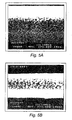
- Electroless deposition methods and pyrolytic methods produce large islands or dots of the material being deposited on the base material. Consequently, continuous coating is obtained at the expense of depositing enough coating material to sufficiently coat the gaps between such large islands or dots. This extensive deposition leads in turn to a thick coating which, because of its thickness, does not generate the best chromatic colors. In short, these conventional methods produce thick coalescence layers.
- a thick coalescence layer has the disadvantageous feature of significantly altering such underlying surface structure.
- photomicrographs of TiO 2 -coated mica that were treated in an electroless cobalt plating bath have been reported as showing finely divided rod-like particles on the surface of the TiO 2 layer. See, for example, U.S. Patent No. 5,116,664 , Fig. 1 and col. 6, lines 10-16, showing and describing a coating with finely divided rod-like particles.
- Chemical methods of deposition and electroless plating methods are typically limited to materials that involve hydrocarbons (liquid or gases), to organometallic compounds, and to metals, such as silver or nickel, that can readily be deposited by electroless processes. It is desirable, however, to manufacture mica interference pigments with methods that permit a much wider choice of materials.
- the present invention provides a coating apparatus as defined in claim 1.
- the apparatus enables uniform deposition of the coating material by directing an inorganic powdered substrate material into a vacuum chamber containing a coating material vaporization source, and generating a coating material vapor from the coating material vaporization source in a dry vacuum process.
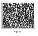
- the powdered substrate material is exposed to the coating material vapor in a substantially uniform manner, and a thin coalescence film of one or more layers of a coating material is formed on the powdered substrate material that substantially replicates a surface microstructure of the powdered substrate material.
- a pigment composition produced using the apparatus of the invention includes a powdered substrate material comprising a plurality of inorganic core particles having an observable surface microstructure.
- a coalescence film substantially surrounds the core particles of the substrate material, and the coalescence film substantially replicates the surface microstructure of the core particles.
- the pigment composition can be combined with various pigment media in order to produce a colorant composition for use in paints, inks, or plastics.
- the pigment particles can be optionally blended with other pigment flakes, particles, or dyes of different hues, chroma and brightness to achieve the color characteristics desired.
- Such pigment compositions exhibit enhanced hiding power, enhanced chroma on a white background and enhanced selected chromas on a black background. These pigment compositions also exhibit a greater available color gamut.
- the hardness and good adherence exhibited by the coalescence films on the pigment particles lead to advantages such as durability and the absence of rub-off coating losses.
- the present invention is directed to apparatus for coating a powdered substrate material to produce optical interference pigment compositions with enhanced colorant effects.
- the apparatus provides for uniform deposition of a coating material from a vaporization source onto a powdered substrate material to form a thin coalescence film of the coating material.
- the thin coalescence film enhances the hiding power and color gamut of the pigment composition.
- a coating material vaporization source used in the deposition process can be selected from an evaporative source, a sputtering source, an electron beam deposition source, an arc vapor deposition source, and the like.
- the pigment composition produced by the apparatus of the invention preferably includes a powdered substrate material comprising a plurality of inorganic core particles having an observable surface microstructure.
- a thin coalescence film substantially surrounds the core particles of the substrate material such that the coalescence film substantially replicates the surface microstructure of the core particles.
- the coated particles of the pigment composition generally have a single-layered or multi-layered interior structure, with a thin continuous layer of the coalescence film substantially surrounding each of the particles.
- the pigment composition can be combined with various pigment media in order to produce a colorant composition for use in paints, inks, or plastics.
- the colorant composition produces a predetermined optical response through radiation incident on a surface coated with the colorant composition.
- the optical response includes enhanced color effects that are due to the coating deposited on the substrate material according to this invention.
- the substrate material can be selected from a variety of particulate materials such as various silicatic materials.
- suitable substrate materials include multilayer platelets such as MgF 2 /Al/MgF 2 platelets, SiO 2 /Al/SiO 2 platelets, and solgel-SiO 2 /AlSiO 2 - solgel platelets, interference glass flakes ( i.e ., glass flakes having a defined thickness in the range from about 0.2 ⁇ m to about 1 ⁇ m), and combinations thereof.
- the MgF 2 , SiO 2 , and solgel-SiO 2 layers on the aluminum cores of the above platelets can have an optical thickness ranging from about 2 quarter waves (qw) at about 400 nm to about 8 qw at about 700 nm.
- the substrate material can be a particulate material, such as mica flakes, glass flakes, talc, boron nitride, and the like, which can be used uncoated, or precoated with a high refractive index material.
- the high refractive index material is preferably a dielectric material with an index of refraction of greater than about 1.65.
- suitable high refractive index dielectric materials include titanium dioxide, zirconium oxide, tin oxide, iron oxide, zinc oxide, tantalum pentoxide, magnesium oxide, tungsten trioxide, carbon, and combinations thereof.
- One preferred substrate material is a TiO 2 -coated silicatic material such as TiO 2 -coated interference mica. The substrate materials described herein can be used singly or in a variety of combinations as desired.
- the coating material can include various light absorbing materials.
- Suitable coating materials include metals, sub-oxides such as metal sub-oxides, oxides including metal oxides, nitrides such as metal nitrides and metaloxynitrides, borides such as metal borides, carbides, sulfides, carbon such as diamond-like carbon and other amorphous carbon ( e.g ., poco, graphite or vitreous) materials.
- Preferred coating materials include gray metals and compounds thereof such as chromium, titanium, palladium, tin, nickel, cobalt, as well as other materials such as silicon, carbon, copper, and aluminum. Various combinations of any of the above coating materials may also be utilized. More generally, coating material choice in this invention includes any material that can be vacuum-deposited, reactively deposited in vacuum, or deposited in plasma assisted vacuum processes.
- An absorber coating composed of a multilayer structure of two or more layers can also be used.
- an alloy or a material composed of extremely thin layers can be deposited.
- the alloy may form spontaneously or may simply be indistinguishable from a multilayered absorber layer since the coating thickness for each layer can be on the order of about 5 Angstroms or less, and even less than about 1 Angstrom.
- the substrate particles travel around the vibrating trays in the chamber, the particles are coated by a thin deposition from each sputter target. The particles not only experience movement under the target, but are agitated under each target as well by a particular vibrating tray.
- Combinations of different absorber coating materials such as Ti/C, Pd/C, Zr/C, Nb/C, Al/C, Cu/C, Ti/W, Ti/Nb, Ti/Si, Al/Si, Pd/Cu, Co/Ni, Cr/Ni, and the like, can be utilized to form a multilayer coating.
- These different material combinations can each be deposited sequentially as alternating layers on the substrate particles so that the coalescent film on the particles is composed of multiple layers of two different absorber materials.
- the different materials used together in the coating each have a refractive index (n) and an absorption coefficient ( k ) that are approximately equal.
- three different coating materials can be employed, or as many different materials can be used as there are targets.
- Alloys can also be used in each target for the coating, such as titanium silicide (TiSi 2 ), Hastelloys (e.g., Ni-Mo-Fe, Ni-Mo-Fe-Cr, Ni-Si-Cu), Monels ( e.g., Ni-Cu), Inconels ( e.g., Ni-Cr-Fe), Nichromes ( e.g., Ni-Cr), and various stainless steels. Details regarding the properties of these and other alloys can be found in the Chemical Engineers' Handbook, McGraw-Hill, 2nd Ed., 2116 (1941 ).
- a coating material includes alternating layers of titanium and carbon (Ti/C) formed on particles of a substrate material such as TiO 2 -coated interference mica.
- the titanium layers are separated by the carbon layers and each particle is encapsulated with a final thin layer of carbon.
- the titanium and carbon layers are sequentially deposited from different targets at a thickness to provide absorbing properties to the coating material.
- the number of layers deposited depends on the thickness of the layers. For example, a larger number of layers are formed for the coating material when each of the layers are a few angstroms thick, whereas fewer layers are formed when each of the layers are many angstroms thick.
- Each of the layers of titanium and carbon can have a thickness ranging from about 1 ⁇ to about 50 ⁇ .
- Another preferred coating of alternating layers includes titanium and silicon (Ti/Si), which can be formed in a similar manner as the Ti/C coating discussed above.
- the carbides are deposited by reactive evaporation of metals with hydrocarbon gas, such as methane.
- Borides are deposited by evaporation of metals in the presence of diborane or halogenated borides, such as BF 3(g) .
- Nitrides are deposited in the presence of nitrogen gas, and oxynitrides are deposited in the presence of gas mixtures, such as oxygen/nitrogen mixtures, air/nitrogen mixtures, and water vapor/nitrogen mixtures. Ammonia may be substituted for the nitrogen if desired. Alternating layers of a metal and a nitride or oxynitride can be formed as the coating material such as titanium/titanium nitride, or titanium/titanium oxynitride.
- the coating material is preferably deposited on the substrate particles so as to form a thin coalescence film having a thickness from about 30 ⁇ to about 150 ⁇ , and preferably a thickness from about 60 ⁇ to about 100 ⁇ .
- the exact thickness depends strongly on the optical properties of the absorbing material.
- the pigment composition can be combined with various pigment media such as acrylic melamine, urethanes, polyesters, vinyl resins, acrylates, methyl methacrylate, ABS resins, epoxies, styrenes, ink and paint formulations based on alkyd resins, and mixtures thereof.
- the pigment composition combined with the pigment media produces a colorant composition that can be used directly as a paint, ink, or moldable plastic material.
- the colorant composition can also be utilized as an additive to conventional paint, ink, or plastic materials.
- the pigment composition can be optionally blended with various additive materials such as conventional pigment flakes, particles, or dyes of different hues, chroma and brightness to achieve the color characteristics desired.
- the pigment composition can be mixed with other conventional pigments, either of the interference type or noninterference type, to produce a range of other colors.
- This preblended composition can then be dispersed into a polymeric medium such as a paint, ink, plastic or other polymeric pigment vehicle for use in a conventional manner.
- suitable additive materials that can be combined with the coated particles of the invention include non-color shifting high chroma or high reflective platelets which produce unique color effects, such as MgF 2 /Al/MgF 2 platelets or SiO 2 /Al/SiO 2 platelets.
- Suitable additives that can be mixed with the pigment composition of the invention include lamellar pigments such as aluminum flakes, graphite flakes, glass flakes, iron oxide, boron nitride, mica flakes, interference based TiO 2 coated mica flakes, interference pigments based on multiple coated platelike silicatic substrates, metal-dielectric or all dielectric interference pigments, and the like; and non-lamellar pigments such as aluminum powder, carbon black, ultramarine blue, cobalt based pigments, organic pigments or dyes, rutile or spinel based inorganic pigments, naturally occurring pigments, inorganic pigments such as titanium dioxide, talc, china clay, and the like; as well as various mixtures thereof.
- pigments such as aluminum powder or carbon black can be added to control lightness and other color properties.
- the pigment composition can be easily and economically utilized in paints and inks for various applications to objects and papers, such as motorized vehicles, currency and security documents, household appliances, architectural structures, flooring, fabrics, sporting goods, electronic packaging/housing, toys, product packaging, etc.
- the pigment composition can also be utilized in forming colored plastic materials, coating compositions, extrusions, electrostatic coatings, glass, and ceramic materials.
- the invention relies on dry, physical vapor deposition methods and vacuum deposition sources.
- the deposition methods produce very fine distributions of nucleation sites on the surface of the material to be coated, and in particular, the deposition methods utilized produce coalescence layers thin enough so as to minimally or negligibly alter the structural features of the underlaying material surface microstructure.
- the thin coalescence layers that can be obtained with such fine nucleation site distributions lead to comparatively thinner coatings, with better chromatic colors.
- the material to be deposited has to be initially evaporated and deposition is subsequently accomplished by depositing the evaporated material on a selected substrate.
- the low temperature vapor deposition methods utilized in the present invention are all physical vapor deposition methods and include resistive evaporation, electron beam deposition, cathodic arc evaporation, carbon rod arc evaporation, magnetron sputtering including both planar and hollow cathode, balanced and unbalanced sputtering, as well as radio frequency sputtering.
- the material In resistive evaporation the material is brought to the evaporation temperature with the aid of a resistance source in an evaporative source.
- a resistance source in an evaporative source.
- an element made of a metal such as tungsten, tantalum or molybdenum holds the material to be evaporated and is heated by passing an intense electric current through the element.
- Arc vapor deposition uses a high intensity current, low voltage arc to vaporize a cathodic electrode (cathodic arc) or anodic electrode (anodic arc) and deposit the vaporized material on a substrate.
- Arc vaporization, especially cathodic arc evaporation, provides copious amounts of film-ions and reactive gas ions.
- the carbon rod arc evaporation differs from the above described cathodic arc evaporation in that the former operates in direct current (DC) mode while the latter operates in alternating current (AC) mode.
- the carbon rods are forced together to form an electrical short which causes high carbon temperature in the contact area, and therefore evaporation.
- Sputtering is ejection by bombardment and sputter deposition is a non-thermal process where the atoms of the material to be evaporated are ejected upon energetic collision with impinging particles that are typically inert gaseous ions and more particularly argon cations.
- the inert gas ions are formed by ionizing collisions with electrons in a vacuum chamber and they are accelerated by an electric potential towards the material to be sputtered.
- the material that is evaporated by sputtering subsequently deposits on a substrate.
- a sputtering cathode and an anode are enclosed in a chamber that contains rarefied inert gas. These electrodes are connected to a high voltage DC power supply which accelerates electrons to the anode. Electrons collide with the inert gas to form inert gas anions that accelerate to the cathode. The anions collide with the sputtering cathode material and vaporize the material that is subsequently deposited on a substrate interposed between the sputtering cathode and the anode.
- This is DC sputtering or more precisely DC diode cathodic sputtering, which typically operates at pressures in the order of 10 -2 Torr.
- the ion formation rate in a sputtering chamber can be enhanced by providing electrons from, for example, a source such as a heated filament.
- the electrons are accelerated by a discharge DC power supply.
- This enhancement in the electron generation rate leads to an increase in the deposition rate, and systems that operate according to this principle are known as triode sputtering systems.
- a sputtering system that, instead of a high voltage DC power supply, has a radio frequency (RF) power supply and a matching chamber is a RF sputtering system.
- This system prevents the charge build-up in a nonconducting material that is to be sputtered and it consequently permits the sputtering of insulating materials, typically being performed at pressures of an order of magnitude as low as 10 -4 Torr.
- Deposition rates achieved with radio frequency sputtering systems can be further increased with magnetron sputtering.
- a plasma exists in the sputtering chamber of a magnetron sputtering device, but appropriately generated magnetic fields additionally force the electrons to follow paths in the region near the sputtering cathode. Accordingly, the frequency of collisions with inert gas atoms is higher and more sputtering ions are formed.
- the progressive increase in sputtering and deposition rates is also characterized by a correspondingly increased ability to perform the deposition at lower pressures.
- an ion source provides a focused, divergent or collimated ion beam.
- the ion beam in the form of a beam plasma, is directed against a sputtering target and the sputtered atoms are deposited on a substrate.
- Reactive sputtering is a sputtering process in which a gas is introduced into the chamber so it reacts with the evaporated material to form a compound that is deposited on the substrate. Even when a compound is sputtered directly, the addition of a reactive gas may be necessary to compensate for the dissociation losses of the reactive component.
- reactive sputtering can arguably be classified as a chemical vapor deposition method
- reactive methods used in this invention rely on vacuum deposition sources that are used in physical vapor deposition methods. In this sense, the reactive deposition methods of this invention are referred to in this context as physical vapor deposition methods.
- Sputtering can be carried out by using "balanced” or "unbalanced” magnetic field confinement.
- "Balanced” magnetron or “standard” sputtering occurs when most of the magnetic field lines are confined to the target region.
- Unbalanced sputtering occurs when an external magnetic field is placed behind the substrate, or the magnets behind the sputtered target are of different strengths so that the ion and electron flux extends out away from the target toward the substrate.
- unbalanced magnetron sputtering rates are higher than for "balanced" magnetron sputtering with higher ion fluxes. Higher fluxes modify the growing deposited film to produce such changes as harder films with differing optical properties.
- Sources of electrons that are used for heating and ionizing atoms and molecules include hot electron emitting surfaces and plasma sources.
- plasma sources electrons are magnetically deflected from a plasma.
- the hollow cathode electron source uses a plasma discharge in a cavity that reflects and traps electrons.
- alternating current magnetron sputtering e.g., "dual magnetron sputtering"
- the voltage between two sputter sources is alternated to facilitate the continuous sputtering of conductors that develop insulating layers in reactive sputtering.
- a reactive gas such as oxygen, nitrogen, methane, and ethylene is introduced near the substrate surface in addition to the noble working gas (e.g., argon).
- the noble working gas e.g., argon
- the MetaModeTM process developed by Optical Coating Laboratory, Inc., ( U.S. Patent Nos. 4,851,095 and 5,225,057 ), allows continuous sputtering of a metallic target where a reactive process takes place in another contiguous chamber. Such a process is useful in making TiO x or SiO x absorbing layers from Ti metal or Si metal depositions.
- the coating apparatus of this invention includes a substrate exposure device.
- the substrate exposure device is configured such that the substrate particles are uniformly exposed to the coating material during the coating process.
- the substrate exposure device is a vibrating a vibrating conveyor or a container coupled to a percussion device, which may be incorporated in a free-fall chamber.
- the substrate exposure device is located within a rarefied chamber (hereinafter referred to as "vacuum chamber").
- the vibrating conveyors e.g ., electromagnetic or pulsating gas-driven devices
- the substrate exposure device itself serves as the chamber whose interior is subject to rarefaction during deposition.
- "waterfall-equipped" chambers and free-fall chambers are embodiments of substrate exposure devices that serve themselves as vacuum chambers.
- the particles of the substrate material are exposed to a vacuum deposition source, such as a hollow cathode sputtering system or a DC magnetron sputtering system.
- a vacuum deposition source such as a hollow cathode sputtering system or a DC magnetron sputtering system.
- a DC magnetron sputter target of chromium was used to deposit a uniform layer of chromium over the surfaces of interference mica.
- Visual inspection revealed that the appearance of the particles went from a pale white to a visual color, and turned gray with further deposition, gray being the color of elemental chromium. Too much chromium coating resulted in the deposition layer being too thick and the coating was opaque.
- the chromium layer was still semi-opaque (partially transmitting), enhanced color could be achieved as well as higher hiding.
- the pigment could be significantly improved in color by adjusting the degree of vibration, the time of deposition, the power to the sputter target, the throw distance, and the amount of substrate pigment being coated.
- embodiments of the coating apparatus of this invention also have a vacuum deposition source as a coating material vaporization source. Exemplary configurations of these elements are illustrated by the embodiments disclosed hereinbelow.
- any of the embodiments of the coating apparatus of this invention herein disclosed provides effective and uniform exposure of the substrate material powder. This means that statistically all the sides of the substrate material powder particles are approximately equally exposed to the coating material that is to be deposited on them. This type of exposure is hereinafter referred to as "uniform exposure”.
- FIG 1A schematically shows a perspective view of a coating apparatus 300 according to a further embodiment of the invention, in which a vacuum chamber 310 encloses both a coating material vaporization source 320 and the substrate exposure device, which is embodied by a vibrating conveyor coater 330.
- vibrating conveyor coater 330 preferably has four conveyors 371, 372, 373, and 374 which are disposed so that the powder of a substrate material 332 effectively circulates counterclockwise as indicated by arrows A5. While the powder circulates along this path, it is effectively mixed so that its exposure to the vaporized coating material is uniform. Efficient mixing also occurs at the end of each conveyor as the powder drops in a waterfall off of one tray and onto the next.
- the vaporized coating material is provided by coating material vaporization source 320, which in one embodiment of this invention is a physical evaporative source. In other embodiments of this invention coating material vaporization source 320 is a magnetron sputtering unit or any of the vacuum deposition sources described hereinabove.
- a vibrating means is provided to force the powder of the substrate material 332 to circulate.
- vibrating conveyor coater 330 can be associated with a plurality of electromagnets 342 which act as the vibrating means.
- Figure 1B schematically shows a side view of conveyor coater 330, and in particular, the components of the electromagnetic conveyors which include a tray 334, a shaft 335, an electromagnet 342, and a spring 344.
- the tray 334 can be made of a variety of materials, and preferably is made of stainless steel. As indicated in Figure 1B , tray 334 is longitudinally tilted with respect to the horizontal plane by an angle that is preferably between about 1° and about 20°, and more preferably between about 1° and about 5°.
- electromagnet 342 is located near a lower end 337 of tray 334 and preferably under such lower end.
- a higher end 339 of tray 334 is preferably cut as shown in Figure 1C , preferably at an angle of about 45° with respect to the longitudinal axis of tray 334.
- One end of spring 344 is preferably attached to electromagnet 342 and its opposite end is attached at a point near lower end 337 of tray 334.
- one end of shaft 335 is attached to electromagnet 342 and the opposite end is attached preferably to a region under tray 334 that is located between the half-length point of tray 334 and lower end 337.
- shaft 335 is conventionally attached to electromagnet 342 to effectively force tray 334 to oscillate according to corresponding oscillations generated by electromagnet 342.
- the restoring effect of spring 344 effectively creates a torque that tends to restore tray 334 to the position that it had prior to the displacement caused by electromagnet 342 acting upon shaft 335.
- the overall dynamic behavior of tray 334 coupled with spring 344 and shaft 335 is such that the powder of substrate material 332 is effectively forced upwards from lower end 337 to higher end 339 along tray 334.
- the vibrating tray can be energized by other vibrating means such as a pulsating gas-driven device.
- a pulsating air piston known as a pneumatic drive, attached to the vibrating tray, can be used to induce the vibrating motion in the tray.
- pneumatic drive systems are available from Martin Engineering (Livonia, MI).
- Each one of trays 334 in the embodiment schematically shown in Figure 1A is disposed so that each higher end 339 is located above lower end 337 of the next tray along the overall circulation path of substrate material 332. This arrangement is shown in the perspective view of Figure 1A and in the side view of Figure 1B .
- conveyor coater 330 has four conveyors, they are disposed with respect to each other in the above described configuration at preferably about 90° angles, as shown in the perspective view of Figure 1A and in the top view of Figure 1C .
- Figure 1B shows tray 334 lengthwise and also shows an end view of the following tray, electromagnet and spring in the sense of circulation of substrate material 332.
- Primed and unprimed numbers in Figure 31B label analogous elements in the lengthwise view and in the end view, respectively.
- Figure 1C shows a top view of the embodiment shown in Figure 1A , where differently shaded areas represent different trays 334 of different conveyors 371-374 forming a closed-loop square array.
- the powder of substrate material 332 is forced to move by the vibration of tray 334 along conveyor 371, and is coated with the vaporized coating material from coating material vaporization source 320.
- the coated powder then drops off at the higher end 339 of conveyor 371 onto lower end 337 of conveyor 372. Consequently, the powder moves along the path indicated by arrows A5.
- the overall powder flow changes travel direction by approximately 90° when it is dropped from one conveyor to the next conveyor along the path.
- the powder falls several inches when it is delivered from one conveyor to the following conveyor so that the powder is thoroughly mixed to provide uniform exposure to the vapor of the coating material that is to deposit on and coat substrate material 332.
- the approximately 45° cut at the higher end 339 of each tray 334 permits a uniform fall of the powder onto the entire width of the lower end 337 of the following tray.
- tray dimensions are about 28 inches long by about 7 inches wide, although commercially available conveyors come in lengths up to 30 feet and widths up to 2 feet. Multiple two-foot wide sputter targets would allow deposition through the length of the larger vibrating trays.
- embodiments of this device could have triangular tray arrangements, pentagonal arrangements, hexagonal arrangements, or arrangements in some other shape.
- Still another embodiment of this device could have a long vibrating tray with multiple overhead evaporating sources. Vibrating conveyors of this type are available from ARBO Engineering (North York, Ontario, Canada) and Eriez (Erie, PA). The preferred arrangement is the square arrangement of vibrating trays with four waterfalls at each 90° turn.
- FIG. 2A schematically shows a vertical cut-away view of a coating apparatus 400 according to another embodiment of the invention, in which the vacuum chamber comprises a tall and narrow elongated coating tower structure such as a free-fall tower 405 with a series of mounted coating material vaporization sources 420 and a container 450 for a substrate material 432.
- the tower 405 is provided with a receptacle 434 to collect and facilitate the subsequent retrieval of a coated substrate material 433.
- coating material vaporization sources 420 are magnetrons. In another embodiment, coating material vaporization sources 420 are hollow cathode sputtering systems.
- magnetrons When magnetrons are utilized for vaporization sources 420, the magnetrons can be mounted in a variety of configurations, but preferably they are mounted in a square or hexagonal configuration, as shown in Figures 2B and 2C .
- Figures 2B and 2C These figures schematically illustrate cross-sectional views of coating apparatus 400 taken in a plane that is orthogonal to the tower's longitudinal axis.
- Figure 2B shows a cross-sectional view of a square tower 406 with four magnetrons 421.
- Figure 2C shows an analogous cross-sectional view of a hexagonal tower 407 with six magnetrons 422.
- Square and hexagonal shaded regions 425 and 426 schematically illustrate the region into which the plasma in towers 406 and 407, respectively, is confined by the magnetic fields of the corresponding magnetrons 421 and 422.
- magnetrons are preferably installed over all sides of the coating tower to increase the deposition rate of the coating material onto the powder particles of substrate material 432.
- the container 450 is provided with a mechanism for appropriately releasing substrate material 432 into tower 405.
- this mechanism is exemplary embodied by a percussion mechanism such as a hammer 452 that, as indicated by double arrow A6, forces the release of substrate material 432 by appropriately shaking container 450.
- This can also be achieved by any other mechanism that produces a similar effect, such as a vibrator.
- substrate material 432 As schematically shown in Figure 2A , after substrate material 432 has been released from container 450, substrate material 432 falls down through a series of plasma regions 427 and past coating material vaporization sources 420. Because of convection and plasma forces, the powder particles spiral down to the bottom where they are collected in receptacle 434. The movement of the powder particles during fall allows for uniform exposure and deposition of a coating material thereon.
- FIG 3A schematically shows a vertical cross-sectional view of a coating apparatus 500 according to an additional embodiment of the invention, in which the vacuum chamber comprises a tall and narrow oblique coating tower 505 with a series of mounted coating material vaporization sources 520 and a container 550 for a substrate material 532.
- the tower 505 is provided with a receptacle 534 to collect and facilitate the subsequent retrieval of a coated substrate material 533.
- coating material vaporization sources 520 are magnetrons.
- the tower 505 stands at an angle preferably in the range of about 70°-89° relative to a horizontal plane intersecting the longitudinal axis of tower 505. Equivalently, tower 505 stands at an angle preferably in the range of about 1°-20° relative to a vertical axis, as shown in Figure 5A .
- Coating material vaporization sources 520 are mounted on one wall of tower 505.
- a device is generally disposed along the wall opposite vaporization sources 520 to force particles of substrate material 532 to undergo a motion such that it renders them fully and uniformly exposed to the coating material that emanates from vaporization sources 520.
- this device is a vibrating tray 508 with ledges that is longitudinally disposed along the wall opposite vaporization sources 520.
- this device is a stationary tray with ledges that is generally disposed as tray 508.
- Figure 3B schematically shows a cross-sectional view of coating apparatus 500 in a plane that is orthogonal to the longitudinal axis.
- tray 508 is provided with longitudinally extending lateral flanges 509 that confine the particles as they run downward over the ledges of tray 508.
- a mechanism such as a vibrator or a similar device forces substrate material 532 to be released from container 550 and to fall down on tray 508. Particles of substrate material 532 slide along the ledges of tray 508, flipping and mixing, and pass through a series of plasma regions 527. The particles are uniformly exposed and coated with the coating material that emanates from coating material vaporization sources 520, resulting in coated substrate material 533 which is collected in receptacle 534.
- Preferred embodiments of the towers schematically shown in Figures 2A and 3A are typically about 3 feet in diameter and about 6 feet long. These embodiments also include (not shown in Figures 2A-3A ) a return mechanism to the top of the tower for further processing of the pigment, if necessary.
- the pigment is circulated through the tower as many times as necessary until the desired color is achieved.
- the return mechanism can be embodied by a screw conveyor, a spiral vibrating elevator, or by a ferris wheel arrangement to reload the powder at container 450 or 550 from the respective receptacle 434 or 534.
- the sputter targets are of suitable dimensions to fit within the chambers.
- the coating is not composed of dot-like or rod-like formations, and the continuous covering is achieved at a much thinner coverage than with other methods, such as electroless or chemical vapor deposition processes.
- Metals and other materials deposited by physical vacuum processes according to the invention can have a thickness of about 30-150 ⁇ , and coalesce at thicknesses that are as small as about 30-50 ⁇ . For example, a coalescence thickness of about 40 ⁇ was commonly achieved in the experiments performed in the context of this invention.
- Deposition is supplemented in some embodiments with a process for altering the chemical makeup of the deposited material.
- the deposited material is oxidized, forming a somewhat thicker layer that increases the durability of the final pigment.
- the pigment product can be baked after vacuum deposition to produce a thicker oxide layer, since a metal layer would be oxidized somewhat after the heating process.
- the thickness of the layers of deposited material that are obtained in this way can be up to about 200 ⁇ while still replicating the underlying structure of the material on which deposition takes place.
- the dry processes are more environmentally friendly and comparatively less hazardous than conventional techniques because the processes of this invention do not produce waste solutions that must be disposed of following the coating processes.
- catalytic ions such as palladium or tin ions that are necessary elements in electrochemical wet chemical methods. The use of such ions may disadvantageously prevent the subsequent use of the manufactured pigments in various consumer products.
- the apparatus of this invention requires no high heating or any pyrolysis. Instead, the coating is deposited by a dry, low temperature process rather than a wet chemical process or a pyrolytic process. More precisely, "dry" in the context of this invention stands for the non-reliance on solutions by the deposition methods. Instead, the dry vacuum methods of this invention are implemented under conditions that are typical of physical vapor deposition techniques.
- the dry vacuum process can be carried out at a temperature of less than about 200°C if desired. In one preferred method, the dry vacuum process is carried out at a near ambient temperature ( e.g ., about 20-60°C). Alternatively, the dry vacuum process can be carried out at a temperature of about 200°C or greater.
- the coatings deposited are highly adherent, hard films that do not rub-off, unlike prior coatings such as carbon coatings that are deposited by pyrolytic processes.
- Organometallic compounds are more expensive than the materials used in physical deposition methods, and some of these compounds are toxic, a property that requires investment in equipment for handling the compounds themselves and for monitoring the processes in which they are used.
- variables x, y, and z which are normalized values of X, Y, and Z, respectively, are known in the art as the chromaticity coordinates, and are routinely used in the industry to quantify aspects of color such as purity, hue, and brightness.
- Another color coordinate system developed by CIE defines color characteristics which account for the dependence of color sensitivity of the eye on viewing angle in terms of X 10 Y 10 Z 10 tristimulus values. These values may be used for viewing angles greater than 4° (and are exact for a viewing angle of 10°), while the values X, Y, and Z are reserved for viewing angles specified for a 4° angle or less.
- X K ⁇ S ⁇ x ⁇ ⁇ R ⁇ d ⁇
- Y K ⁇ S ⁇ y ⁇ ⁇ R ⁇ d ⁇
- Z K ⁇ S ⁇ z ⁇ ⁇ R ⁇ d ⁇
- K 100 / ( ⁇ S( ⁇ )y'( ⁇ )d ⁇ ) S( ⁇ ) is the relative spectral power distribution of the illuminant
- x'( ⁇ ), y'( ⁇ ), and z'( ⁇ ) are the color matching functions for a specified angle
- R( ⁇ ) is the spectral reflectance of the specimen.
- chromaticity diagram From the x, y, z chromaticity coordinates, a useful diagram known as the "chromaticity diagram" can be plotted, wherein the loci of x and y values correspond to all real colors; which in conjunction with the human eye response function and the third dimension of brightness (which may be conveniently plotted on an axis perpendicular to the chromaticity plane), can be used to completely describe all aspects of perceived color.
- This system of color description is particularly useful when a quantitative comparison of color attributes is required.
- the chromaticity plane may be described in a variety of ways; however, a standard in the industry is known as the L*a*b* color space defined by CIE (hereinafter referred to as the "CIELab space").
- CIE CIE
- L* indicates lightness
- a* and b* are the chromaticity coordinates.
- the a* axis is perpendicular to the b* axis, with increasingly positive values of a* signifying deepening chroma of red and increasingly negative values of a* signify deepening chroma of green.
- the L*a*b* color system allows for a comparison of the color differences between two measurements through a metric, namely AE, which indicates the change in color as measured in the L*a*b* color space.
- AE a metric
- the L*a*b* set of coordinates is one of such sets of three items.
- Another set incorporates lightness, L*, but instead of the coordinates a* and b*, it uses the coordinates C* and h, that stand for chroma and hue, respectively.
- Chroma measures color saturation. Increasing fading corresponds to lower saturation. Hue corresponds with the dominant saturated color.
- DCATM Dynamic Color AreaTM
- DCATM metric is measured using a goniospectrophotometer, which is an instrument that allows for the configuration of nearly 300 distinct measurement geometries.
- the DCATM metric can also be applied to other multi-angle measurement geometries. Calculating the DCATM metric under two different geometries allows for a comparison of pigment appearance under two simulated viewing environments.
- the DCATM metric is represented by the area in the a*-b* plane defined by the function f(a*, b*). The larger the area defined by the DCATM metric for a given pigment, the larger that pigment's color gamut.
- the DCATM metric is described as a defined surface integral ⁇ ⁇ f a * , b * ⁇ db * da * where the integrations are performed between the lower and upper limits b 1 , b 2 , respectively, for b*, and the lower and upper limits a 1 , a 2 , respectively, for a*.
- This double integral provides an area in the a*-b* plane of the CIELab space. This area, and thus the DCATM metric, is measured in square CIE units.
- TiO 2 -coated interference mica having the colors of Super Green Pearl, Violet Pearl and Gold Pearl under the tradename MasterTint® was obtained from DuPont.
- TiO 2 -coated mica under the tradename Iriodin® was also obtained from E. Merck (Darmstadt, Germany). Samples of Iriodin® 221 Blue, Iriodin® 289 Flash Interference Blue, and Iriodin® 299 Flash Interference Green were used.
- a sample under the Mearlin tradename labelled Super Red Mearlin Luster pigment was obtained from the Englehard Corporation (Ossining, New York).
- Similar interference mica can be obtained from Kemira Oy (Pori, Finland), under the tradename Flonac.
- the substrate material was placed in a coating apparatus according to this invention, for example, a vibrating bed in a vacuum chamber.
- Other experiments used a rotating or an oscillatory drum coater, electromagnetic conveyors, or free falling coating towers.
- Gold Pearl interference pigment was first washed in acetone and dried in an air oven. The dried pigment was then placed in a cooled dish placed in a vacuum chamber pumped to a pressure of about 1.10 -4 Torr and subjected to DC magnetron coating of chromium in an Ar pressure of about 2.5 ⁇ 10 -3 Torr.
- Violet Pearl pigment was treated as described in Example 1. It was also sputter coated with chromium.
- Iriodin® 221 Blue pigment was coated with chromium in a barrel vacuum coater equipped with two chromium magnetron sources measuring 5"x15" in size. The magnetrons were run at about 3 A at 3 mTorr Ar for between 6 and 20 min depending on the color enhancement required. A mass of about 25-50 g of powder was processed without any pre-treatment, washing or drying.
- Example 1-7 The pigments identified in Examples 1-7 were utilized with no additional coating as control pigments. Cr-coated pigments according to Examples 1-7 and the control pigments were sprayed onto white and onto black coated paper panels to produce test samples. The sprayed materials included 25% by weight of pigment loading in an acrylic-melamine binder. The dried sprayed material was about 1 mil thick. The microscopic characteristics and colors of the control and Cr-coated samples are discussed below.
- Figures 6A-6B , and 7A-7C show scanning electron microscopic pictures of sprayed control pigments and Cr-coated pigments according to this invention.
- Figures 6A and 7A show scanning electron microscopic pictures of the surfaces of control Gold Pearl pigment at 50000x and control Super Green Pearl pigment at 75000x, respectively.
- Figures 6B and 7B show, respectively, scanning electron microscopic pictures of the surface at 50000x of the chromium-coated Gold Pearl pigment in Example 1, and of the surface at 75000x of the chromium-coated Super Green Pearl in Example 2.
- Figure 7C shows a scanning electron microscopic picture of the surface at 100000x of Super Green Pearl pigment that was coated with Cr as described in Example 2.
- the chromium coated pigments in some samples exhibited a higher chroma, a higher dynamic color shift, and a higher hiding power. Hue changes, i.e., color changes, were also noted.
- the higher hiding power was readily seen by comparing spray out samples on white paper panels.
- the control samples on the white paper background showed a slight reflection in color at near normal angle, but at a glancing angle the white paper was readily visible.
- the control showed little difference in reflection at normal versus glancing angle, i.e., the colors were practically the same.
- the chromium-coated pigment showed little, if any, difference in color whether it was sprayed over a black or white background.
- the pigment itself was also notably different.
- the control pigment was whitish in color whereas the Cr-coated pigment was colored.
- control samples on a white background only showed reflected color at near normal incidence. At higher angles, only the mass tone of the white background is seen. In contrast, the treated Cr-coated interference mica showed the color of the pigment at all angles. This observation implies a much improved hiding power (hiding the background color) over the control samples.
- Table 1 shows the difference between the color parameters for the control pigments on white and on black paper panels versus the Cr-coated pigments also on white and on black paper panels for the samples in Examples 1-3.
- the L*a*b* coordinates were measured at 10° incidence with a D 65 illuminant (CIE illuminant with a color temperature of 6504 K) with a Data Color 600 color integrating measuring instrument.
- DCATM calculations were based on color measurements using off-gloss (i.e., specular) geometry on a Zeiss GK 311M spectrophotometer. As described hereinabove, DCATM is a measure of the color gamut available as the angle of viewing is changed.
- the DCATM values in Table 1 for the Cr-coated pigments are greater than the corresponding values for the control samples by a factor in the range of approximately 1.4-2.6. This means that the available color gamut for the Cr-coated pigments has been increased by the same factor.
- the chroma for the Violet Pearl + Cr is still higher than the chroma for the control with no chromium on the white background because the chroma for the control on a white background is initially very low.
- the chroma and DCATM values will increase, but with additional chromium deposition the chroma and DCATM values will ultimately decrease as the pigment behaves more like chromium powder.
- the intensification of chroma with the added layer of chromium is due to an increase in absorption and interference effects.
- Figure 8 is a plot in a*b* color space that shows the hue and chroma changes for the three DuPont pigments in Examples 1-3 as the viewing angles change.
- the Cr-coated pigment as sprayed with the binder on white background has higher chroma than the corresponding control sample as similarly sprayed with the binder on white background. This is shown in Figure 8 by the location of the chroma point loci for the Cr-coated pigments and those for the corresponding control samples.
- the chroma point loci for the Cr-coated pigments are farther from the center of the a*b* axis system than point loci for the corresponding control samples. This is also satisfied for the chroma point loci when the background is black for the pigments in Examples 1 and 2.
- the loci of chroma points 802 and 804 in Figure 8 correspond to the Gold Pearl interference pigment in Example 1 on white background in the form of control sample and with Cr-coating according to this invention, respectively.
- the loci of chroma points 812, 814 and 822, 824 correspond to the pigments Super Green Pearl in Example 2 and Violet Pearl in Example 3, respectively.
- the loci 812 and 822 are for the control samples on a white background and the loci 814 and 824 are for the Cr-coated pigments also on white background.
- the pair of loci chroma points 812, 814 is for the pigment in Example 2 and the pair of chroma points 822, 824 is for the pigment in Example 3.
- the sets of loci of chroma points 804, 814 and 824 for the Cr-coated pigments on white background are farther from the origin of the a*b* coordinate system than the respective counterparts 802, 812 and 822 for the control samples on white background.
- the sets of loci of chroma points 803 and 813 for the Cr-coated pigments on black background in Examples 1 and 2 are also farther from the origin of the a*b* coordinate system than the respective counterparts 801 and 811 for the control samples on black background.
- the angle of detection is listed in the third column under the heading "View”.
- the gloss angle is the angle for which the angle of incidence is equal to the angle of reflection, and the difference between the gloss angle and the angle of detection is the angle listed in the fourth column under the heading "Diff.” for each measurement.
- the fifth column in each table under the heading "Filt.” provides the neutral density filter setting, where unity means that no filter was used.
- Points (a*, b*) in this Table correspond to triangles in Figure 9 .
- N° Illum View Diff. Fill.
- 45 90 45 1 10.30 8.73 18.60 35.46 16.77 -22.79 28.30 306.34 4
- 45 110 25 1 31.63 23.70 57.78 55.79 37.34 -38.93 53.94 313.81 5 45 120 15 1 57.92 41.42 103.57 70.47 51.57 -48.55 70.83 316.72
- Points (a*, b*) in this Table correspond to filled squares in Figure 9 .
- Points (a*, b*) in this Table correspond to crosses in Figure 9 .
- Points (a*, b*) in this Table correspond to filled diamonds in Figure 10 .
- Points (a*, b*) in this Table correspond to triangles in Figure 10 .
- N° Illum View Diff. Filt. X Y Z L* a* b* C* h 1 130 155 -105 1 17.60 18.91 17.36 50.59 -1.77 5.84 6.10 106.86 2 45 70 65 1 21.13 22.59 18.50 54.65 -1.37 10.51 10.60 97.43 3 45 90 45 1 35.80 38.10 25.57 68.09 -1.08 21.01 21.03 92.94 4 45 110 25 1 90.79 96.71 51.95 98.71 -1.62 40.76 40.79 92.27 5 45 120 15 1 145.09 154.20 77.74 118.02 -1.47 51.45 51.47 91.63
- Table 8 Sample: Cr-coated Gold Pearl in Example 1 on white background.
- Points (a*, b* in this Table correspond to squares in Figure 10 .
- 86.60 4 45 110 25 1 70.08 73.27 40.14 88.58 1.31 36.22 36.24 87.92 5 45 120 15 1 138.59 144.49 70.70 115.14 2.19 52.09 52.14 87.59
- Table 9 Sample: Cr-coated Gold Pearl in Example 1 on black background.
- Points (a*, b*) in this Table correspond to crosses in Figure 10 .
- Points (a*, b*) in this Table correspond to filled diamonds in Figure 11 .
- Points (a*, b*) in this Table correspond to triangles in Figure 11 .
- Points (a*, b*) in this Table correspond to squares in Figure 11 .
- 45 110 25 1 53.75 65.16 49.14 84.57 -19.65 19.25 27.51 135.59 5 45 120 15 1 94.25 117.89 93.15 106.54 -29.17 20.51 35.66 144.89 Table 13 Sample: Cr-coated Super Green Pearl in Example 2 on black background.
- Points (a*, b*) in this Table correspond to crosses in Figure 11 .
- N° Illum View Diff. Filt. X Y Z L* a* b* C* h 1 130 155 -105 1 4.70 5.54 5.85 28.21 -6.85 0.42 6.87 176.51 2 45 70 65 1 7.68 9.10 7.84 36.17 -8.54 6.37 10.65 143.30 3
- Points (a*, b*) in this Table correspond to filled diamonds in Figure 12 .
- Points (a*, b*) in this Table correspond to squares in Figure 12 .
- Points (a*, b*) in this Table correspond to triangles in Figure 12 .
- Points (a*, b*) in this Table correspond to crosses in Figure 12 .
- N° Illum View Diff. Filt. X Y Z L* a* b* C* h 1 45 70 65 1 7.38 6.83 8.07 31.41 9.15 -2.68 9.53 343.70 2
- 90 45 1 14.03 12.41 14.25 41.86 15.07 -2.26 15.24 351.47 3
- 110 25 1 39.74 33.77 36.38 64.78 26.01 -0.17 26.01 359.63 4
- Table 18 Sample: Control Merck Iriodin® 221 Blue in Example 4 on white background.
- Points (a*, b*) in this Table correspond to filled diamonds in Figure 13 .
- Points (a*, b*) in this Table correspond to squares in Figure 13 .
- N° Illum View Diff. Filt. X Y Z L* a* b* C* h 1 45 70 65 1 18.59 20.53 32.40 52.43 -4.48 -16.17 16.78 254.52 2 45 90 45 1 22.40 25.28 42.96 57.35 -7.04 -20.93 22.08 251.40 3 45 110 25 1 35.00 39.58 81.09 69.17 -8.44 -35.30 36.30 256.56 4 45 120 15 1 45.35 50.24 115.12 76.22 -6.46 -45.72 46.18 261.96 5 130 155 -105 1 19.02 20.31 30.82 52.19 -1.20 -14.38 14.43 265.24 Table 20 Sample: Cr-coated Merck Iriodin® 221 Blue in Example 4 on white background.
- Points (a*, b*) in this Table correspond to triangles in Figure 13 .
- N° Illum View Diff. Filt. X Y Z L* a* b* C* h 1 45 70 65 1 9.23 9.95 14.17 37.74 -1.64 -9.17 9.31 259.84 2 45 90 45 1 14.19 15.64 25.72 46.50 -3.94 -16.46 16.92 256.54 3 45 110 25 1 30.97 33.98 71.26 64.94 -4.56 -34.91 35.21 262.56 4 45 120 15 1 45.84 49.26 113.80 75.61 -2.45 -45.99 46.05 266.95 5 130 155 -105 1 7.37 7.69 10.48 33.34 0.72 -7.04 7.08 275.83
- Table 21 Sample: Cr-coated Merck Iriodin® 221 Blue in Example 4 on black background.
- Points (a*, b*) in this Table correspond to crosses in Figure 13 .
- Points (a*, b*) in this Table correspond to filled diamonds in Figure 14.
- N° Illum View Diff. Filt. X Y Z L* a* b* C* h 1 45 70 65 1 64.02 65.80 47.85 84.90 3.77 21.18 21.51 79.91 2 45 90 45 1 68.11 70.52 56.17 87.25 2.75 16.85 17.08 80.73 3 45 110 25 1 90.20 97.93 110.29 99.19 -4.77 -3.21 5.75 213.93 4 45 120 15 1 128.74 143.80 222.82 114.93 -10.68 -29.39 31.27 250.02 5 130 155 -105 1 63.93 67.22 50.28 85.61 0.46 19.87 19.88 88.68 Table 23 Sample: Control Iriodin® Flash Interference Blue in Example 5 on black background.
- Points (a*, b*) in this Table correspond to squares in Figure 14.
- N° Illum View Diff. Filt. X Y Z L* a* b* C* h 1 45 70 65 1 12.32 13.40 22.27 43.36 -2.63 -16.06 16.27 260.68 2
- 90 45 1 15.89 17.80 29.89 49.25 -5.58 -18.10 18.94 252.88 3
- 110 25 1 34.88 41.12 76.30 70.26 -13.54 -29.76 32.70 245.53 4
- Table 24 Sample: Cr-coated Iriodin® Flash Interference Blue in Example 5 on white background.
- Points (a*, b*) in this Table correspond to triangles in Figure 14.
- N° Illum View Diff. Filt. X Y Z L* a* b* C* h 1 45 70 65 1 5.30 5.70 8.42 28.64 -1.20 -8.64 8.72 262.12 2 45 90 45 1 8.93 9.88 15.17 37.62 -3.64 -11.73 12.28 252.75 3 45 110 25 1 29.16 32.78 55.52 63.98 -7.23 -22.64 23.77 252.28 4
- 45 120 15 1 70.04 77.93 144.18 90.75 -8.14 -36.62 37.51 257.47 5 130 155 -105 1 3.58 3.73 5.51 22.75 -0.65 -7.50 7.53 274.96
- Points (a*, b*) in this Table correspond to crosses in Figure 14.
- N° Illum View Diff. Filt. X Y Z L* a* b* C* h 1 45 70 65 1 4.54 4.94 7.85 26.58 -1.95 -10.22 10.40 259.17 2 45 90 45 1 7.72 8.59 13.73 35.18 -3.92 -12.52 13.12 252.61 3 45 110 25 1 23.37 26.22 44.38 58.24 -6.52 -20.98 21.97 252.75 4
- Points (a*, b*) in this Table correspond to filled diamonds in Figure 15.
- Points (a*, b*) in this Table correspond to squares in Figure 15.
- N° Illum View Diff. Filt. X Y Z L* a* b* C* h 1 45 70 65 1 6.45 7.17 11.38 32.18 -3.53 -11.59 12.11 253.06 2
- 45 90 45 1 10.59 12.35 15.21 41.76 -8.15 -4.69 9.40 209.90 3
- 45 110 25 1 37.53 46.25 39.58 73.71 -19.55 11.24 22.55
- 150.10 4 45 120 15 1 87.38 109.71 85.80 103.64 -29.10 20.66 35.69 144.63 5 130 155 -105 1 5.46 5.98 10.53 29.35 -2.40 -14.04 14.24 260.28
- Table 28 Sample: Cr-coated Iriodin® Flash Interference Green in Example 6 on white background.
- Points (a*, b*) in this Table correspond to triangles in Figure 15.
- Points (a*, b*) in this Table correspond to crosses in Figure 15.
- N° Illum View Diff. Filt. X Y Z L* a* b* C* h 1 45 70 65 1 6.87 7.58 10.27 33.09 -3.11 -6.85 7.52 245.57 2
- Figures 9-15 show the plots of the data given in Tables 2-29 for the respective pigments: Violet Pearl, Gold Pearl, Super Green Pearl, Super Red Mearlin Luster, Merck Iriodin® 221 Blue, Iriodin® 289 Flash Interference Blue, and Iriodin® 299 Flash Interference Green.
- the color characteristics are plotted in the a*b* space for the corresponding control sample on white and on black backgrounds and for the Cr-coated pigment according to this invention on white and on black backgrounds.
- Figures 9-15 invariably show in all cases that the Cr-coated pigments which may be produced by the apparatus of this invention gave nearly the same color trajectory on both the white and black backgrounds whereas the control samples gave widely different color trajectories.
- One of the practical consequences of this new attribute is that it allows a paint shop more freedom in repairs, especially when the paint is covering different colored bases.
Landscapes
- Chemical & Material Sciences (AREA)
- Organic Chemistry (AREA)
- Materials Engineering (AREA)
- Engineering & Computer Science (AREA)
- Chemical Kinetics & Catalysis (AREA)
- Life Sciences & Earth Sciences (AREA)
- Wood Science & Technology (AREA)
- Mechanical Engineering (AREA)
- Metallurgy (AREA)
- Inorganic Chemistry (AREA)
- General Chemical & Material Sciences (AREA)
- Pigments, Carbon Blacks, Or Wood Stains (AREA)
- Physical Vapour Deposition (AREA)
- Glass Compositions (AREA)
- Nitrogen Condensed Heterocyclic Rings (AREA)
Claims (10)
- Un appareil d'enduction (300, 400) destiné à déposer un mince film de coalescence sur un matériau en poudre formant substrat (332, 432), comprenant :une chambre à vide (310) ;une source de vaporisation de matériau d'enduction (320, 420) disposée au sein de la chambre à vide (310) ; et,i) un enducteur convoyeur vibrant (330) capable de faire circuler un matériau en poudre formant substrat (332) et d'exposer le matériau formant substrat (332) de manière substantiellement uniforme à de la vapeur de matériau d'enduction produite par la source de vaporisation (320) ; ouii) un conteneur (450) couplé à un dispositif à percussion (452) capable de faire circuler un matériau en poudre formant substrat (432) et d'exposer le matériau formant substrat (432) de manière substantiellement uniforme à de la vapeur de matériau d'enduction produite par la source de vaporisation (420).
- L'appareil d'enduction (300, 400) de la revendication 1, où la source de vaporisation de matériau d'enduction (320, 420) est sélectionnée dans le groupe consistant en une source d'évaporation, une source de pulvérisation, une source de dépôt par faisceau d'électrons, et une source de dépôt en phase vapeur par arc.
- L'appareil d'enduction (300) de la revendication 1, où l'enducteur convoyeur vibrant (330) comporte quatre convoyeurs (371, 372, 373, 374) qui sont agencés de manière à se chevaucher selon un modèle rectangulaire de façon à ce que le matériau en poudre formant substrat (332) se déplace de façon efficace d'un convoyeur (371, 372, 373, 374) à un convoyeur adjacent (372, 373, 374, 371).
- L'appareil d'enduction (300) de la revendication 3, où la source de vaporisation de matériau d'enduction (320) est disposée au-dessus d'un ou de plusieurs convoyeurs (371, 372, 373, 374).
- L'appareil d'enduction (300) de la revendication 3, où les convoyeurs (371, 372, 373, 374) comportent chacun un plateau (334) destiné à tenir le matériau en poudre formant substrat (332), et un dispositif vibrant (335, 342, 344) disposé en dessous du plateau (334) et raccordé en opération au plateau (334).
- L'appareil d'enduction (300) de la revendication 5, où chaque plateau (334) est incliné longitudinalement par rapport à un plan horizontal de façon à ce qu'une extrémité supérieure (339) d'un plateau (334) chevauche une extrémité inférieure (337) d'un plateau adjacent (334).
- L'appareil d'enduction (300) de la revendication 6, où chaque plateau (334) est incliné à un angle d'environ 1' à environ 20'.
- L'appareil d'enduction (300) de la revendication 1, où l'enducteur convoyeur vibrant (330) est un dispositif électromagnétique.
- L'appareil d'enduction (300) de la revendication 1, où l'enducteur convoyeur vibrant (330) est un dispositif pulsatoire entraîné par gaz.
- L'appareil d'enduction (300) de la revendication 1, où l'enducteur convoyeur vibrant (330) comporte trois convoyeurs qui sont agencés de manière à se chevaucher selon un modèle triangulaire de façon à ce que le matériau en poudre formant substrat (332) se déplace de façon efficace d'un convoyeur à un convoyeur adjacent.
Applications Claiming Priority (3)
| Application Number | Priority Date | Filing Date | Title |
|---|---|---|---|
| US09/389,962 US6241858B1 (en) | 1999-09-03 | 1999-09-03 | Methods and apparatus for producing enhanced interference pigments |
| US09/539,695 US6524381B1 (en) | 2000-03-31 | 2000-03-31 | Methods for producing enhanced interference pigments |
| EP00948607A EP1224242B1 (fr) | 1999-09-03 | 2000-07-10 | Procedes et dispositif de production de pigments d'interference ameliores |
Related Parent Applications (2)
| Application Number | Title | Priority Date | Filing Date |
|---|---|---|---|
| EP00948607.7 Division | 2000-07-10 | ||
| EP00948607A Division EP1224242B1 (fr) | 1999-09-03 | 2000-07-10 | Procedes et dispositif de production de pigments d'interference ameliores |
Publications (3)
| Publication Number | Publication Date |
|---|---|
| EP1666546A2 EP1666546A2 (fr) | 2006-06-07 |
| EP1666546A3 EP1666546A3 (fr) | 2008-09-03 |
| EP1666546B1 true EP1666546B1 (fr) | 2010-10-20 |
Family
ID=27012926
Family Applications (2)
| Application Number | Title | Priority Date | Filing Date |
|---|---|---|---|
| EP00948607A Expired - Lifetime EP1224242B1 (fr) | 1999-09-03 | 2000-07-10 | Procedes et dispositif de production de pigments d'interference ameliores |
| EP05021553A Expired - Lifetime EP1666546B1 (fr) | 1999-09-03 | 2000-07-10 | Procédé et dispositif pour la production de pigments d'interférence améliorés |
Family Applications Before (1)
| Application Number | Title | Priority Date | Filing Date |
|---|---|---|---|
| EP00948607A Expired - Lifetime EP1224242B1 (fr) | 1999-09-03 | 2000-07-10 | Procedes et dispositif de production de pigments d'interference ameliores |
Country Status (6)
| Country | Link |
|---|---|
| EP (2) | EP1224242B1 (fr) |
| AT (2) | ATE485345T1 (fr) |
| AU (1) | AU6208200A (fr) |
| DE (2) | DE60045136D1 (fr) |
| TW (1) | TWI239986B (fr) |
| WO (1) | WO2001018127A1 (fr) |
Cited By (5)
| Publication number | Priority date | Publication date | Assignee | Title |
|---|---|---|---|---|
| US10052903B2 (en) | 2014-07-29 | 2018-08-21 | Sicpa Holding Sa | Processes for in-field hardening of optical effect layers produced by magnetic-field generating devices generating concave field lines |
| US11577273B2 (en) | 2018-07-30 | 2023-02-14 | Sicpa Holding Sa | Processes for producing optical effects layers |
| US11618053B2 (en) | 2019-01-15 | 2023-04-04 | Sicpa Holding Sa | Process for producing optical effect layers |
| US11847527B2 (en) | 2019-02-28 | 2023-12-19 | Sicpa Holding Sa | Verifiable access credential |
| US12020864B2 (en) | 2018-07-30 | 2024-06-25 | Sicpa Holding Sa | Assemblies and processes for producing optical effect layers comprising oriented magnetic or magnetizable pigment particles |
Families Citing this family (38)
| Publication number | Priority date | Publication date | Assignee | Title |
|---|---|---|---|---|
| US6686042B1 (en) | 2000-09-22 | 2004-02-03 | Flex Products, Inc. | Optically variable pigments and foils with enhanced color shifting properties |
| US6569529B1 (en) | 2000-10-10 | 2003-05-27 | Flex Product, Inc. | Titanium-containing interference pigments and foils with color shifting properties |
| DE102005037095A1 (de) * | 2005-08-03 | 2007-02-08 | Merck Patent Gmbh | System von Interferenzpigmenten |
| EP2505618A1 (fr) * | 2011-04-01 | 2012-10-03 | Fábrica Nacional De Moneda Y Timbre | Utilisation des marqueurs de sécurité absorbant des ondes éléctromagnétique |
| TWI641660B (zh) | 2013-08-05 | 2018-11-21 | 瑞士商西克帕控股有限公司 | 磁性或可磁化色料顆粒及光學效應層 |
| WO2015085505A1 (fr) | 2013-12-11 | 2015-06-18 | Sicpa Holding Sa | Fils et bandes de sécurité variables dans le plan optique |
| CA2929739C (fr) | 2013-12-13 | 2021-11-09 | Sicpa Holding Sa | Procede de production de couches a effets |
| RU2668545C2 (ru) | 2014-02-13 | 2018-10-01 | Сикпа Холдинг Са | Защитные нити и полоски |
| PL2965920T3 (pl) | 2014-07-09 | 2018-03-30 | Sicpa Holding Sa | Optycznie zmienne magnetyczne nitki zabezpieczające i paski |
| RU2017105124A (ru) | 2014-07-30 | 2018-08-28 | Сикпа Холдинг Са | Способы получения слоев с оптическим эффектом с применением ременного привода |
| TW201703879A (zh) | 2015-06-02 | 2017-02-01 | 西克帕控股有限公司 | 用於生產光學效應層之製程 |
| JP2018522257A (ja) | 2015-07-01 | 2018-08-09 | シクパ ホルディング ソシエテ アノニムSicpa Holding Sa | 郵便切手 |
| JP6789217B2 (ja) * | 2015-07-22 | 2020-11-25 | 株式会社フルヤ金属 | 粉末コーティング装置 |
| TWI709626B (zh) | 2015-10-15 | 2020-11-11 | 瑞士商西克帕控股有限公司 | 用於製造包含定向非球面磁性或可磁化顏料顆粒的光學效應層之磁性組件與製程 |
| KR102588551B1 (ko) | 2015-11-10 | 2023-10-12 | 시크파 홀딩 에스에이 | 배향된 비-구형 자성 또는 자화성 안료 입자를 포함하는 광학 효과층 생성 장치 및 방법 |
| AR107681A1 (es) | 2016-02-29 | 2018-05-23 | Sicpa Holding Sa | Aparatos y procesos para producir capas con efecto óptico que comprenden partículas de pigmento no esféricas orientadas magnéticas, o magnetizables |
| EP3178569A1 (fr) | 2016-06-29 | 2017-06-14 | Sicpa Holding Sa | Procédés et dispositifs pour produire des couches à effet optique au moyen d'un photomasque |
| ES2877158T3 (es) | 2016-07-29 | 2021-11-16 | Sicpa Holding Sa | Procesos para producir capas de efecto |
| EP3500374B1 (fr) | 2016-08-16 | 2021-04-07 | Sicpa Holding Sa | Procédés de production de couches d'effets |
| RS61414B1 (sr) | 2016-09-22 | 2021-03-31 | Sicpa Holding Sa | Aparati i procesi za proizvodnju slojeva optičkog efekta obuhvatajući orijentisane nesferične magnetne ili magnetizovane pigmentne čestice |
| CA2988898C (fr) | 2016-12-21 | 2021-05-11 | Viavi Solutions Inc. | Particules comportant un colorant depose par vapeur |
| CA2988904C (fr) | 2016-12-21 | 2020-05-05 | Viavi Solutions Inc. | Pigment metallique colore hybride |
| TWI773805B (zh) | 2017-08-25 | 2022-08-11 | 瑞士商西克帕控股有限公司 | 用於產生包括經定向非球面扁球狀的磁性或可磁化顏料粒子的光學效果層的組件及進程 |
| TWI768096B (zh) | 2017-08-25 | 2022-06-21 | 瑞士商西克帕控股有限公司 | 光學效果層、用於產生此光學效果層的裝置及進程、及此裝置的使用方法 |
| TWI780201B (zh) | 2017-08-25 | 2022-10-11 | 瑞士商西克帕控股有限公司 | 光學效果層及其使用方法、包括此光學效果層的安全性文件或裝飾構件、及用於產生此光學效果層的裝置及進程 |
| TWI794359B (zh) | 2018-01-17 | 2023-03-01 | 瑞士商西克帕控股有限公司 | 用於生產光學效應層之製程 |
| US11577272B2 (en) | 2018-05-08 | 2023-02-14 | Sicpa Holding Sa | Magnetic assemblies, apparatuses and processes for producing optical effect layers comprising oriented non-spherical magnetic or magnetizable pigment particles |
| TWI829734B (zh) | 2018-09-10 | 2024-01-21 | 瑞士商西克帕控股有限公司 | 光學效應層、生產其之製程、及包含其之安全文件、裝飾元件及物件 |
| CN109628887A (zh) * | 2019-01-20 | 2019-04-16 | 邱晖 | 一种真空镀膜机 |
| JP7463633B2 (ja) | 2019-02-08 | 2024-04-09 | シクパ ホルディング ソシエテ アノニム | 配向される非球形で扁平の磁性又は磁化可能顔料粒子を含む、光学効果層を製造するための磁気組立体及びプロセス |
| TWI844619B (zh) | 2019-02-28 | 2024-06-11 | 瑞士商西克帕控股有限公司 | 利用可攜式裝置來認證磁感應標記之方法 |
| EP3946757B1 (fr) | 2019-03-28 | 2023-05-03 | Sicpa Holding Sa | Ensembles magnétiques et leurs procédés de production de couches à effet optique comprenant des particules pigmentaires magnétiques ou magnétisables orientées non sphériques |
| AU2020376218B2 (en) | 2019-10-28 | 2025-09-04 | Sicpa Holding Sa | Magnetic assemblies and processes for producing optical effect layers comprising oriented non-spherical magnetic or magnetizable pigment particles |
| WO2021083809A1 (fr) | 2019-10-28 | 2021-05-06 | Sicpa Holding Sa | Ensembles magnétiques et procédés de production de couches à effet optique comprenant des particules de pigments magnétiques ou magnétisables non sphériques orientées |
| AU2021279119A1 (en) | 2020-05-26 | 2023-02-02 | Sicpa Holding Sa | Magnetic assemblies and methods for producing optical effect layers comprising oriented platelet-shaped magnetic or magnetizable pigment particles |
| CN114196336A (zh) * | 2022-01-07 | 2022-03-18 | 山东中科泰阳光电科技有限公司 | 一种彩色光伏封装胶膜 |
| CN115491672B (zh) * | 2022-09-21 | 2023-11-24 | 中机新材料研究院(郑州)有限公司 | 一种超高速激光熔覆涂层表面微气孔的修复装置及其方法 |
| WO2026052662A1 (fr) | 2024-09-06 | 2026-03-12 | Sicpa Holding Sa | Dispositifs magnétiques, appareils magnétiques et procédés de production de couches à effet optique comprenant des particules de pigment magnétiques ou magnétisables non sphériques orientées |
Family Cites Families (4)
| Publication number | Priority date | Publication date | Assignee | Title |
|---|---|---|---|---|
| CA1329867C (fr) * | 1988-07-20 | 1994-05-31 | Hiroshi Ito | Pigment |
| DE69111375T2 (de) * | 1990-11-02 | 1996-01-04 | Nisshin Steel Co Ltd | Pigment und Verfahren zur Herstellung. |
| JPH10158541A (ja) * | 1996-11-27 | 1998-06-16 | Nisshin Steel Co Ltd | 耐候性,光輝性に優れたダークシルバー色メタリック顔料 |
| EP0927749B1 (fr) * | 1997-12-29 | 2003-02-26 | Sicpa Holding S.A. | Composition de revêtement, utilisation de particules, procédé pour marquer et identifier un document de valeur pourvu d'un tel revêtement |
-
2000
- 2000-07-10 AT AT05021553T patent/ATE485345T1/de not_active IP Right Cessation
- 2000-07-10 DE DE60045136T patent/DE60045136D1/de not_active Expired - Lifetime
- 2000-07-10 AT AT00948607T patent/ATE480599T1/de not_active IP Right Cessation
- 2000-07-10 AU AU62082/00A patent/AU6208200A/en not_active Abandoned
- 2000-07-10 DE DE60044942T patent/DE60044942D1/de not_active Expired - Lifetime
- 2000-07-10 EP EP00948607A patent/EP1224242B1/fr not_active Expired - Lifetime
- 2000-07-10 WO PCT/US2000/018795 patent/WO2001018127A1/fr not_active Ceased
- 2000-07-10 EP EP05021553A patent/EP1666546B1/fr not_active Expired - Lifetime
- 2000-08-02 TW TW089115531A patent/TWI239986B/zh not_active IP Right Cessation
Cited By (5)
| Publication number | Priority date | Publication date | Assignee | Title |
|---|---|---|---|---|
| US10052903B2 (en) | 2014-07-29 | 2018-08-21 | Sicpa Holding Sa | Processes for in-field hardening of optical effect layers produced by magnetic-field generating devices generating concave field lines |
| US11577273B2 (en) | 2018-07-30 | 2023-02-14 | Sicpa Holding Sa | Processes for producing optical effects layers |
| US12020864B2 (en) | 2018-07-30 | 2024-06-25 | Sicpa Holding Sa | Assemblies and processes for producing optical effect layers comprising oriented magnetic or magnetizable pigment particles |
| US11618053B2 (en) | 2019-01-15 | 2023-04-04 | Sicpa Holding Sa | Process for producing optical effect layers |
| US11847527B2 (en) | 2019-02-28 | 2023-12-19 | Sicpa Holding Sa | Verifiable access credential |
Also Published As
| Publication number | Publication date |
|---|---|
| AU6208200A (en) | 2001-04-10 |
| DE60045136D1 (de) | 2010-12-02 |
| EP1224242A1 (fr) | 2002-07-24 |
| WO2001018127A1 (fr) | 2001-03-15 |
| EP1666546A3 (fr) | 2008-09-03 |
| EP1224242B1 (fr) | 2010-09-08 |
| TWI239986B (en) | 2005-09-21 |
| EP1666546A2 (fr) | 2006-06-07 |
| ATE480599T1 (de) | 2010-09-15 |
| ATE485345T1 (de) | 2010-11-15 |
| DE60044942D1 (de) | 2010-10-21 |
Similar Documents
| Publication | Publication Date | Title |
|---|---|---|
| EP1666546B1 (fr) | Procédé et dispositif pour la production de pigments d'interférence améliorés | |
| US6676741B2 (en) | Methods for producing enhanced interference pigments | |
| US6241858B1 (en) | Methods and apparatus for producing enhanced interference pigments | |
| US7235300B2 (en) | Titanium-containing interference pigments and foils with color shifting properties | |
| US5662738A (en) | Luster pigments based on multiply coated plateletlike metallic substrates | |
| JP5856737B2 (ja) | 高導電性の光学可変性顔料 | |
| KR100455328B1 (ko) | 착색된광택안료 | |
| JP6118782B2 (ja) | 顔料の使用 | |
| KR102557547B1 (ko) | 금속 특성을 갖는 비금속 안료 | |
| CN1425046A (zh) | 多层珠光颜料 | |
| US6310118B1 (en) | Coloring material composition | |
| CN102365335A (zh) | 在纳米级金属颗粒上具有梯度的pvd金属效果颜料、其生产方法及其用途 | |
| CN107124885B (zh) | 导电彩色干涉颜料 | |
| CZ300777B6 (cs) | Kompozice tiskarských barev, smes pro její výrobu a bezpecnostní dokument | |
| JPH06313124A (ja) | 磁化可能な光輝顔料 | |
| Jiang et al. | Preparation and characterization of Fe2O3 coating on quartz fabric by electron beam evaporation | |
| ES2972524T3 (es) | Uso de una formulación de barniz que contiene pigmentos de efecto metálico para el barnizado de un vehículo equipado con un sensor de radar y un sensor lidar | |
| KR20240135544A (ko) | 광의 분산을 통해 시각적 효과를 제공하는 감성 소재 및 이의 제조 방법 | |
| JPH10101957A (ja) | 2色の色調を発現する顔料 | |
| JP2003292824A (ja) | 黒色顔料及びその製造方法 | |
| MXPA99012002A (en) | Pigment mixture |
Legal Events
| Date | Code | Title | Description |
|---|---|---|---|
| PUAI | Public reference made under article 153(3) epc to a published international application that has entered the european phase |
Free format text: ORIGINAL CODE: 0009012 |
|
| AC | Divisional application: reference to earlier application |
Ref document number: 1224242 Country of ref document: EP Kind code of ref document: P |
|
| AK | Designated contracting states |
Kind code of ref document: A2 Designated state(s): AT BE CH CY DE DK ES FI FR GB GR IE IT LI LU MC NL PT SE |
|
| PUAL | Search report despatched |
Free format text: ORIGINAL CODE: 0009013 |
|
| AK | Designated contracting states |
Kind code of ref document: A3 Designated state(s): AT BE CH CY DE DK ES FI FR GB GR IE IT LI LU MC NL PT SE |
|
| 17P | Request for examination filed |
Effective date: 20081120 |
|
| 17Q | First examination report despatched |
Effective date: 20090114 |
|
| AKX | Designation fees paid |
Designated state(s): AT BE CH CY DE DK ES FI FR GB GR IE IT LI LU MC NL PT SE |
|
| GRAP | Despatch of communication of intention to grant a patent |
Free format text: ORIGINAL CODE: EPIDOSNIGR1 |
|
| GRAS | Grant fee paid |
Free format text: ORIGINAL CODE: EPIDOSNIGR3 |
|
| GRAA | (expected) grant |
Free format text: ORIGINAL CODE: 0009210 |
|
| RAP1 | Party data changed (applicant data changed or rights of an application transferred) |
Owner name: JDS UNIPHASE CORPORATION |
|
| AC | Divisional application: reference to earlier application |
Ref document number: 1224242 Country of ref document: EP Kind code of ref document: P |
|
| AK | Designated contracting states |
Kind code of ref document: B1 Designated state(s): AT BE CH CY DE DK ES FI FR GB GR IE IT LI LU MC NL PT SE |
|
| REG | Reference to a national code |
Ref country code: GB Ref legal event code: FG4D |
|
| REG | Reference to a national code |
Ref country code: CH Ref legal event code: EP |
|
| REG | Reference to a national code |
Ref country code: IE Ref legal event code: FG4D |
|
| REG | Reference to a national code |
Ref country code: CH Ref legal event code: NV Representative=s name: MURGITROYD & COMPANY |
|
| REF | Corresponds to: |
Ref document number: 60045136 Country of ref document: DE Date of ref document: 20101202 Kind code of ref document: P |
|
| REG | Reference to a national code |
Ref country code: NL Ref legal event code: VDEP Effective date: 20101020 |
|
| PG25 | Lapsed in a contracting state [announced via postgrant information from national office to epo] |
Ref country code: NL Free format text: LAPSE BECAUSE OF FAILURE TO SUBMIT A TRANSLATION OF THE DESCRIPTION OR TO PAY THE FEE WITHIN THE PRESCRIBED TIME-LIMIT Effective date: 20101020 Ref country code: AT Free format text: LAPSE BECAUSE OF FAILURE TO SUBMIT A TRANSLATION OF THE DESCRIPTION OR TO PAY THE FEE WITHIN THE PRESCRIBED TIME-LIMIT Effective date: 20101020 Ref country code: PT Free format text: LAPSE BECAUSE OF FAILURE TO SUBMIT A TRANSLATION OF THE DESCRIPTION OR TO PAY THE FEE WITHIN THE PRESCRIBED TIME-LIMIT Effective date: 20110221 Ref country code: FI Free format text: LAPSE BECAUSE OF FAILURE TO SUBMIT A TRANSLATION OF THE DESCRIPTION OR TO PAY THE FEE WITHIN THE PRESCRIBED TIME-LIMIT Effective date: 20101020 Ref country code: SE Free format text: LAPSE BECAUSE OF FAILURE TO SUBMIT A TRANSLATION OF THE DESCRIPTION OR TO PAY THE FEE WITHIN THE PRESCRIBED TIME-LIMIT Effective date: 20101020 |
|
| PG25 | Lapsed in a contracting state [announced via postgrant information from national office to epo] |
Ref country code: GR Free format text: LAPSE BECAUSE OF FAILURE TO SUBMIT A TRANSLATION OF THE DESCRIPTION OR TO PAY THE FEE WITHIN THE PRESCRIBED TIME-LIMIT Effective date: 20110121 Ref country code: BE Free format text: LAPSE BECAUSE OF FAILURE TO SUBMIT A TRANSLATION OF THE DESCRIPTION OR TO PAY THE FEE WITHIN THE PRESCRIBED TIME-LIMIT Effective date: 20101020 |
|
| PG25 | Lapsed in a contracting state [announced via postgrant information from national office to epo] |
Ref country code: ES Free format text: LAPSE BECAUSE OF FAILURE TO SUBMIT A TRANSLATION OF THE DESCRIPTION OR TO PAY THE FEE WITHIN THE PRESCRIBED TIME-LIMIT Effective date: 20110131 |
|
| PLBE | No opposition filed within time limit |
Free format text: ORIGINAL CODE: 0009261 |
|
| STAA | Information on the status of an ep patent application or granted ep patent |
Free format text: STATUS: NO OPPOSITION FILED WITHIN TIME LIMIT |
|
| PG25 | Lapsed in a contracting state [announced via postgrant information from national office to epo] |
Ref country code: DK Free format text: LAPSE BECAUSE OF FAILURE TO SUBMIT A TRANSLATION OF THE DESCRIPTION OR TO PAY THE FEE WITHIN THE PRESCRIBED TIME-LIMIT Effective date: 20101020 |
|
| 26N | No opposition filed |
Effective date: 20110721 |
|
| REG | Reference to a national code |
Ref country code: DE Ref legal event code: R097 Ref document number: 60045136 Country of ref document: DE Effective date: 20110721 |
|
| PG25 | Lapsed in a contracting state [announced via postgrant information from national office to epo] |
Ref country code: IT Free format text: LAPSE BECAUSE OF FAILURE TO SUBMIT A TRANSLATION OF THE DESCRIPTION OR TO PAY THE FEE WITHIN THE PRESCRIBED TIME-LIMIT Effective date: 20101020 |
|
| PG25 | Lapsed in a contracting state [announced via postgrant information from national office to epo] |
Ref country code: MC Free format text: LAPSE BECAUSE OF NON-PAYMENT OF DUE FEES Effective date: 20110731 |
|
| REG | Reference to a national code |
Ref country code: IE Ref legal event code: MM4A |
|
| PG25 | Lapsed in a contracting state [announced via postgrant information from national office to epo] |
Ref country code: IE Free format text: LAPSE BECAUSE OF NON-PAYMENT OF DUE FEES Effective date: 20110710 |
|
| PG25 | Lapsed in a contracting state [announced via postgrant information from national office to epo] |
Ref country code: LU Free format text: LAPSE BECAUSE OF NON-PAYMENT OF DUE FEES Effective date: 20110710 Ref country code: CY Free format text: LAPSE BECAUSE OF EXPIRATION OF PROTECTION Effective date: 20101020 |
|
| REG | Reference to a national code |
Ref country code: FR Ref legal event code: PLFP Year of fee payment: 17 |
|
| REG | Reference to a national code |
Ref country code: CH Ref legal event code: PFA Owner name: VIAVI SOLUTIONS INC., US Free format text: FORMER OWNER: JDS UNIPHASE CORPORATION, US |
|
| REG | Reference to a national code |
Ref country code: DE Ref legal event code: R082 Ref document number: 60045136 Country of ref document: DE Representative=s name: MURGITROYD & COMPANY, DE Ref country code: DE Ref legal event code: R081 Ref document number: 60045136 Country of ref document: DE Owner name: VIAVI SOLUTIONS INC. (N. D. GES. D. STAATES DE, US Free format text: FORMER OWNER: JDS UNIPHASE CORP., MILPITAS, CALIF., US |
|
| REG | Reference to a national code |
Ref country code: FR Ref legal event code: CA Effective date: 20170208 Ref country code: FR Ref legal event code: CD Owner name: VIAVI SOLUTIONS INC., US Effective date: 20170208 |
|
| REG | Reference to a national code |
Ref country code: FR Ref legal event code: PLFP Year of fee payment: 18 |
|
| REG | Reference to a national code |
Ref country code: FR Ref legal event code: PLFP Year of fee payment: 19 |
|
| PGFP | Annual fee paid to national office [announced via postgrant information from national office to epo] |
Ref country code: DE Payment date: 20190726 Year of fee payment: 20 Ref country code: FR Payment date: 20190725 Year of fee payment: 20 |
|
| PGFP | Annual fee paid to national office [announced via postgrant information from national office to epo] |
Ref country code: GB Payment date: 20190726 Year of fee payment: 20 |
|
| PGFP | Annual fee paid to national office [announced via postgrant information from national office to epo] |
Ref country code: CH Payment date: 20190729 Year of fee payment: 20 |
|
| REG | Reference to a national code |
Ref country code: DE Ref legal event code: R071 Ref document number: 60045136 Country of ref document: DE |
|
| REG | Reference to a national code |
Ref country code: CH Ref legal event code: PL |
|
| REG | Reference to a national code |
Ref country code: GB Ref legal event code: PE20 Expiry date: 20200709 |
|
| PG25 | Lapsed in a contracting state [announced via postgrant information from national office to epo] |
Ref country code: GB Free format text: LAPSE BECAUSE OF EXPIRATION OF PROTECTION Effective date: 20200709 |