EP1667353A1 - Procédé et dispositif de décodage de paquets de données dans une procédure ARQ hybride - Google Patents
Procédé et dispositif de décodage de paquets de données dans une procédure ARQ hybride Download PDFInfo
- Publication number
- EP1667353A1 EP1667353A1 EP04028736A EP04028736A EP1667353A1 EP 1667353 A1 EP1667353 A1 EP 1667353A1 EP 04028736 A EP04028736 A EP 04028736A EP 04028736 A EP04028736 A EP 04028736A EP 1667353 A1 EP1667353 A1 EP 1667353A1
- Authority
- EP
- European Patent Office
- Prior art keywords
- decoding
- fact
- encoded packet
- fec code
- fec
- Prior art date
- Legal status (The legal status is an assumption and is not a legal conclusion. Google has not performed a legal analysis and makes no representation as to the accuracy of the status listed.)
- Withdrawn
Links
- 238000000034 method Methods 0.000 title claims abstract description 110
- 238000012545 processing Methods 0.000 claims abstract description 25
- 230000015654 memory Effects 0.000 claims description 63
- 230000009897 systematic effect Effects 0.000 claims description 20
- 230000005540 biological transmission Effects 0.000 claims description 11
- 238000004891 communication Methods 0.000 claims description 10
- 230000001413 cellular effect Effects 0.000 claims description 3
- 101150012579 ADSL gene Proteins 0.000 claims description 2
- 102100020775 Adenylosuccinate lyase Human genes 0.000 claims description 2
- 108700040193 Adenylosuccinate lyases Proteins 0.000 claims description 2
- 101100370254 Homo sapiens TPX2 gene Proteins 0.000 abstract description 17
- 102100024813 Targeting protein for Xklp2 Human genes 0.000 abstract description 17
- 239000000872 buffer Substances 0.000 description 34
- 238000004422 calculation algorithm Methods 0.000 description 15
- 230000007935 neutral effect Effects 0.000 description 11
- 101000642258 Homo sapiens Spondin-2 Proteins 0.000 description 10
- 102100036427 Spondin-2 Human genes 0.000 description 10
- 102100040496 Collagen alpha-2(VIII) chain Human genes 0.000 description 8
- 101000749886 Homo sapiens Collagen alpha-2(VIII) chain Proteins 0.000 description 8
- 101000969594 Homo sapiens Modulator of apoptosis 1 Proteins 0.000 description 8
- 102100021440 Modulator of apoptosis 1 Human genes 0.000 description 8
- 239000011159 matrix material Substances 0.000 description 8
- 238000012937 correction Methods 0.000 description 6
- 102100021753 Cardiolipin synthase (CMP-forming) Human genes 0.000 description 3
- 201000001925 Fuchs' endothelial dystrophy Diseases 0.000 description 3
- 101000895518 Homo sapiens Cardiolipin synthase (CMP-forming) Proteins 0.000 description 3
- 230000008901 benefit Effects 0.000 description 3
- 229940003304 dilt Drugs 0.000 description 3
- 101000979001 Homo sapiens Methionine aminopeptidase 2 Proteins 0.000 description 2
- 101000969087 Homo sapiens Microtubule-associated protein 2 Proteins 0.000 description 2
- 102100023174 Methionine aminopeptidase 2 Human genes 0.000 description 2
- 101100385368 Saccharomyces cerevisiae (strain ATCC 204508 / S288c) CSG2 gene Proteins 0.000 description 2
- 101150115304 cls-2 gene Proteins 0.000 description 2
- 125000004122 cyclic group Chemical group 0.000 description 2
- 238000013461 design Methods 0.000 description 2
- 208000010718 Multiple Organ Failure Diseases 0.000 description 1
- 238000013459 approach Methods 0.000 description 1
- 230000003139 buffering effect Effects 0.000 description 1
- 238000004364 calculation method Methods 0.000 description 1
- 238000006243 chemical reaction Methods 0.000 description 1
- 239000000470 constituent Substances 0.000 description 1
- 238000001514 detection method Methods 0.000 description 1
- 239000000284 extract Substances 0.000 description 1
- 208000035928 fuchs endothelial 2 corneal dystrophy Diseases 0.000 description 1
- 230000001788 irregular Effects 0.000 description 1
- 238000012804 iterative process Methods 0.000 description 1
- 238000004377 microelectronic Methods 0.000 description 1
- 238000004088 simulation Methods 0.000 description 1
Images


Classifications
-
- H—ELECTRICITY
- H04—ELECTRIC COMMUNICATION TECHNIQUE
- H04L—TRANSMISSION OF DIGITAL INFORMATION, e.g. TELEGRAPHIC COMMUNICATION
- H04L1/00—Arrangements for detecting or preventing errors in the information received
- H04L1/12—Arrangements for detecting or preventing errors in the information received by using return channel
- H04L1/16—Arrangements for detecting or preventing errors in the information received by using return channel in which the return channel carries supervisory signals, e.g. repetition request signals
- H04L1/18—Automatic repetition systems, e.g. Van Duuren systems
- H04L1/1829—Arrangements specially adapted for the receiver end
- H04L1/1835—Buffer management
- H04L1/1845—Combining techniques, e.g. code combining
-
- H—ELECTRICITY
- H04—ELECTRIC COMMUNICATION TECHNIQUE
- H04L—TRANSMISSION OF DIGITAL INFORMATION, e.g. TELEGRAPHIC COMMUNICATION
- H04L1/00—Arrangements for detecting or preventing errors in the information received
- H04L1/004—Arrangements for detecting or preventing errors in the information received by using forward error control
- H04L1/0045—Arrangements at the receiver end
- H04L1/0047—Decoding adapted to other signal detection operation
- H04L1/005—Iterative decoding, including iteration between signal detection and decoding operation
-
- H—ELECTRICITY
- H04—ELECTRIC COMMUNICATION TECHNIQUE
- H04L—TRANSMISSION OF DIGITAL INFORMATION, e.g. TELEGRAPHIC COMMUNICATION
- H04L1/00—Arrangements for detecting or preventing errors in the information received
- H04L1/004—Arrangements for detecting or preventing errors in the information received by using forward error control
- H04L1/0045—Arrangements at the receiver end
- H04L1/0055—MAP-decoding
-
- H—ELECTRICITY
- H04—ELECTRIC COMMUNICATION TECHNIQUE
- H04L—TRANSMISSION OF DIGITAL INFORMATION, e.g. TELEGRAPHIC COMMUNICATION
- H04L1/00—Arrangements for detecting or preventing errors in the information received
- H04L1/004—Arrangements for detecting or preventing errors in the information received by using forward error control
- H04L1/0056—Systems characterized by the type of code used
- H04L1/0057—Block codes
-
- H—ELECTRICITY
- H04—ELECTRIC COMMUNICATION TECHNIQUE
- H04L—TRANSMISSION OF DIGITAL INFORMATION, e.g. TELEGRAPHIC COMMUNICATION
- H04L1/00—Arrangements for detecting or preventing errors in the information received
- H04L1/004—Arrangements for detecting or preventing errors in the information received by using forward error control
- H04L1/0056—Systems characterized by the type of code used
- H04L1/0064—Concatenated codes
- H04L1/0066—Parallel concatenated codes
-
- H—ELECTRICITY
- H04—ELECTRIC COMMUNICATION TECHNIQUE
- H04L—TRANSMISSION OF DIGITAL INFORMATION, e.g. TELEGRAPHIC COMMUNICATION
- H04L1/00—Arrangements for detecting or preventing errors in the information received
- H04L1/12—Arrangements for detecting or preventing errors in the information received by using return channel
- H04L1/16—Arrangements for detecting or preventing errors in the information received by using return channel in which the return channel carries supervisory signals, e.g. repetition request signals
- H04L1/18—Automatic repetition systems, e.g. Van Duuren systems
- H04L1/1812—Hybrid protocols; Hybrid automatic repeat request [HARQ]
- H04L1/1816—Hybrid protocols; Hybrid automatic repeat request [HARQ] with retransmission of the same, encoded, message
-
- H—ELECTRICITY
- H04—ELECTRIC COMMUNICATION TECHNIQUE
- H04L—TRANSMISSION OF DIGITAL INFORMATION, e.g. TELEGRAPHIC COMMUNICATION
- H04L1/00—Arrangements for detecting or preventing errors in the information received
- H04L1/12—Arrangements for detecting or preventing errors in the information received by using return channel
- H04L1/16—Arrangements for detecting or preventing errors in the information received by using return channel in which the return channel carries supervisory signals, e.g. repetition request signals
- H04L1/18—Automatic repetition systems, e.g. Van Duuren systems
- H04L1/1812—Hybrid protocols; Hybrid automatic repeat request [HARQ]
- H04L1/1819—Hybrid protocols; Hybrid automatic repeat request [HARQ] with retransmission of additional or different redundancy
Definitions
- hybrid ARQ schemes are used to guarantee an error free transmission of data packets.
- FEC Forward Error Correction
- the invention is more particularly directed to HARQ systems of types II or III.
- LDPC Low Density Parity Check
- the main challenge in the receiver is the management of the needed memory to store the soft values for the combination process.
- the soft values are being combined before the deployment of the channel decoder.
- the previously received packet soft values
- the stored packet and the new packet need to be combined.
- the combined packet is then processed by the channel decoder.
- a goal of the invention is to propose another solution, totally different from the solution of the prior art, for performing the combination between the data of the previous packet and the data of the current packet.
- Another goal of the invention is to simplify the implementation of the overall outer modem including the decoder.
- Another goal of the invention is to improve the decoding precision.
- the invention proposes, according to an embodiment, a method of decoding an incident FEC code encoded packet of data within an ARQ scheme.
- the method comprises successive decoding processes of successive intermediate FEC code encoded packets related to said incident FEC code encoded packet.
- Each decoding process includes a FEC code decoding.
- a current decoding process comprises:
- the inventors have observed that using the code decoding results of the preceding FEC code decoding (i.e. the decoding of the previously received packet) for elaborating the initial decoding conditions of the current decoding process (i.e. the decoding process concerning the current received packet) permits to combine the information contained in the previous packet with the information contained in the current received packet.
- the shadow memory is advantageously the feed-back interleaver memory of the turbo-code decoder.
- the preceding decoding results in the sense of the invention are set to neutral values, for example a "0" logic values, such that the initial decoding conditions of the first FEC code decoding is obtained from said first intermediate FEC code encoded packet.
- the invention can be applicable either to an hybrid ARQ system of type II, or to an hybrid ARQ system of type III, i.e. an hybrid ARQ system with incremental redundancy technique.
- a current intermediate FEC code encoded packet comprises for example a received encoded group of data resulting from the transmission of a punctured FEC code encoded packet obtained from a puncturing of said incident FEC code encoded data with a current puncturing mask.
- said current intermediate FEC code encoded packet comprises additional reference data, in general neutral values, for example zero logic values, which replace the punctured bits.
- NACK negative acknowledgement
- each intermediate FEC code encoded packet is a received packet resulting from the transmission of at least a part of said incident FEC code encoded packet.
- said incident FEC code encoded packet may be punctured or not. But if said incident packet is punctured with a puncturing mask, the same puncturing mask will be used for all the eventual next transmissions caused by the reception of a negative acknowledgement (NACK).
- NACK negative acknowledgement
- said incident FEC code encoded packet may be an incident Low Density Parity Check (LDPC) code encoded packet and each FEC code decoding comprises a LDPC code decoding process.
- LDPC Low Density Parity Check
- Said combination of the data of said current intermediate LDPC code encoded packet with the decoding result concerning the preceding intermediate LDPC code encoded packet may comprise, for example, a summation or a weighted summation.
- the device comprises processing means for performing successive decoding processes of successive intermediate FEC code encoded packets related to said incident FEC code encoded packet.
- Said processing means includes a FEC decoder.
- Said processing means further comprises determination means for determining initial decoding conditions from the FEC code decoding result concerning the preceding intermediate FEC code encoded packet and from said current intermediate FEC code encoded packet.
- said FEC decoder is adapted to perform the current FEC code decoding using said initial decoding conditions.
- said Turbo code decoder is adapted to perform an iterative Soft-In-Soft-Out decoding process for delivering Log-Likelihood-Ratios called LLRs.
- Said initial decoding conditions comprises the data of said current intermediate FEC code encoded packet and the previous LLRs delivered by said Turbo code decoder at the end of the Turbo code decoding process concerning the preceding intermediate FEC code encoded packet .
- said Turbo code decoder comprises at least one MAP decoder adapted to implement two decoding processes of the Maximum-A-Posteriori (MAP) type.
- the data of said current intermediate FEC code encoded packet comprise systematic values, first parity values and second parity values.
- Said initial decoding conditions comprises :
- said Turbo code decoder comprises :
- said Turbo code decoder comprises several auxiliary deinterleaving memories respectively adapted to store several previous LLRs respectively associated to several different independent ARQ schemes.
- said LDPC decoding means comprises check nodes including a processing unit and first storing means, and variable nodes including a processing unit and second storing means.
- the first storing means of said check nodes are adapted to contain the decoding result of the LDPC decoding process.
- Said determination means comprises combination means included in said variable nodes for combining the data of said current intermediate LDPC encoded packet with the decoding result concerning the preceding intermediate LDPC encoded packet, and storing said initial decoding conditions in said second storing means of the variable nodes.
- an hybrid ARQ system comprising a device such as the one defined above.
- Such an element may form a cellular mobile phone.
- the transmitter side which can be for example a base station in an UMTS wireless communication system, comprises a CRC (Cyclic Redundancy Check) encoder CRCE followed by a forward error correction (FEC) code encoder FECC.
- CRC Cyclic Redundancy Check
- FEC forward error correction
- a module MODS connected to the output of the encoder FECC, is adapted for performing a modulation as well as a spreading.
- the encoded packet of data are then transmitted on a channel towards a receiver TP which can be for example a cellular mobile phone.
- the binary information bits are encoded with a cyclic redundancy check (CRC) code for error detection. These encoded binary information bits are then channel-encoded with a forward error correction (FEC) code with coding rate R. After having received the packet, the receiver checks the quality of the received packet after FEC decoding. If some errors are detected, a negative acknowledgment NACK is sent back to the transmitter.
- CRC cyclic redundancy check
- FEC forward error correction
- this NACK requires retransmission of the same encoded packet.
- the retransmitted packets are not identical to the original transmission packet.
- the retransmitted packet carries additional redundancy information, i.e. parity bits for error correction.
- the soft decision data sequence of the erroneous packet is stored in a buffer at the receiver side and it is combined symbol by symbol with the retransmitted packet before FEC decoding.
- the additional redundancy is combined with the previously received packet and the resulting more powerful FEC code word with coding rate R is decoded.
- the basic structure of a receiver according to the prior art is extended, in order to perform a hybrid ARQ process, by adding a combination unit and a memory buffer before the FEC decoder.
- the combination unit performs the combination of the stored packets and the newly received additional data packet in the case of a retransmission.
- the invention proposes a solution which is totally different from that used in the prior art, for performing the decoding of an incident encoded packet within an ARQ scheme.
- the incident FEC code encoded packet to be decoded is punctured (step 20) by using a puncturing mask.
- the punctured encoded packet is transmitted (step 21).
- an intermediate FEC code encoded packet is elaborated (step 23) from the encoded received packet and from additional reference data, generally neutral logic values, for example "0" logic values. In other words, the punctured bits are replaced by "0" values.
- initial decoding conditions are determined (step 24) from the content of said intermediate encoded packet and from the decoding result of the FEC decoding of the preceding intermediate encoded packet.
- the preceding decoding result is replaced by neutral logic values, for example "0" logic values, so that the initial decoding conditions are determined from the content of the first intermediate encoded packet.
- the FEC code decoding is performed (step 25) using said initial decoding conditions.
- the decoding result is then analyzed (step 28).
- an ACK is transmitted (step 27), and another incident encoded packet can be eventually processed.
- the flow chart of figure 2 is also applicable.
- the puncturing step 20 is optional.
- the same packet is retransmitted. That means in particular that the same puncturing mask, if any, is used for all the transmission related to the incident encoded packet to be decoded. Of course, for another incident encoded packet to be decoded, the puncturing mask, if any, may be different or not.
- the turbo-code encoder FECC1 is here a UMTS turbo-code encoder. It consists of two constituent convolutional encoders and an interleaver.
- the convolutional codes are fixed to be RSC (Recursive Codes) codes.
- hard values or soft values can be relevant.
- Hard values may indicate if a symbol is supposed to be "1" or "0".
- the extrinsic values ⁇ 2,int generated in the first step are feedback to the next iteration using deinterleaver 1 .
- the input values from deinterleaver 1 to MAP 1 decoder are set to 0, which represents the neutral value of the intrinsic information.
- the calculated extrinsic information is used at the a priori input of MAP 1 .
- turbo-decoding as well as the structure of such conventional turbo-code decoders implementing MAP or Max Log MAP algorithms, are well known from the man skilled in the art, for example from EP 1 398 881.
- turbo-code decoder FECD1 More precisely, such an embodiment of a turbo-code decoder FECD1 according to the invention is depicted in figure 4.
- the decoder FECD1 comprises an input buffering module IM for performing in particular a serial to parallel conversion which converts the soft values stream coming from the channel into three parallel streams of systematic values x 1 , first parity value y 1 and the interleaved second parity value y 2 .
- the decoding process is performed by two MAP decoders MAP 1 and MAP 2 . Although two separate MAP units can be used, only one MAP unit can be used. In such a case, the MAP 1 and MAP 2 operation are done serially on the same MAP unit.
- the two MAP decoders are connected by an interleaver IL1.
- An output deinterleaver DILT performs the deinterleaving of the output values resulting in the data stream x est .
- Decoding Turbo codes by searching the most likely codeword is far too complex. Therefore iterative decoding is advised.
- the two convolutional codes are decoded separately. While doing this, each decoder incorporates information that has been gathered by the other. This "gathering of information” is the exchange of soft-output values, where the bit-estimates of one unit are transformed into a priori information for the next.
- the decoders hence have to be soft-input soft-output (SISO) units, for example MAP units.
- SISO soft-input soft-output
- a main deinterleaving memory DIL1 is connected between the extrinsic output of the MAP 2 unit and the a priori input of the MAP 1 unit, through two switches SW1 and SW2.
- an auxiliary deinterleaving memory DIL2 is connected between the LLR output of the MAP 2 unit and the a priori input of the MAP 1 unit through the switches SW1 and SW2.
- the main deinterleaving memory is adapted to store and deinterleave the extrinsic information ⁇ 2,int delivered by the second MAP decoding process whereas the auxiliary deinterleaving memory DIL2 is adapted to store and deinterleave the previous LLRs (called LLR 2,int ), resulting from the decoding of a previously received packet.
- LLR 2,int previous LLRs
- the second switch SW2 is adapted for delivering either said deinterleaved extrinsic information or said deinterleaved previous LLRs to said first MAP decoding process MAP 1 .
- the deinterleaving memory can be split into an active (here, deinterleaver DIL1) which is being used in the actual turbo-decoding iteration and a shadow memory (here, DIL2).
- the active memory the extrinsic information is processed.
- the shadow memory stores the LLR values obtained from the last turbo-code decoding iteration.
- An incident turbo-code encoded packet of data which comprises systematic value x 1 , first parity value y 1 and second parity value y 2 , is to be decoded.
- x 1 , y 1 and y 2 represent respectively the systematic values, the first parity values and the second parity values of the first intermediate turbo-code encoded packet.
- the initial conditions are constituted by the systematic values x 1 , the first and second parity values y 1 and y 2 as well as the values "0" (figure 5) which represent the neutral values of the extrinsic information.
- the input values from deinterleaver DIL1 to the MAP 1 unit are set to 0.
- the calculated extrinsic information ⁇ 2 is used at the input of the MAP 1 unit (figure 6).
- the switches SW1 and SW2 are positioned so that the deinterleaving memory DIL1 is connected between the extrinsic output of the MAP 2 unit and the a priori input of the MAP 1 unit.
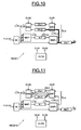
- the LLR values LLR 2,int are delivered to the output deinterleaver DILT for obtaining the output data stream x est . Further, the control means CLTM send the control signal CLS1 so that these LLR values are also stored in the shadow memory DIL2 (figure 7).
- a negative acknowledgment is sent to the transmitter by the receiver and the transmitter will send additional symbols to increase the coding performance.
- This might be a complete packet or incremental information segments, depending on the used ARQ scheme.
- this additional information would be combined with the existing information in a combining unit located outside of the decoder, and then delivered into the decoder. The decoder would then start a new round of decoding iterations.
- this combination will be performed by the decoder FECD1 by using the stored LLR values related to the preceding packet reception, i.e. the LLR values stored in the shadow memory DIL2 related to the decoding of the first intermediate packet.
- a second intermediate encoded packet is elaborated as described above for the first intermediate packet.
- x 1 , y 1 and y 2 represent respectively the systematic values, the first parity values and the second parity values of said second intermediate encoded packet.
- the initial conditions are constituted by the values x 1 , y 1 and y 2 as well as by the LLR values LLR 2 stored in the shadow memory DIL2 and related to the decoding of the first intermediate packet.
- the second intermediate packet is then turbo decoded as for the first intermediate packet (figure 9).
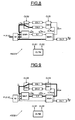
- the LLR values (decoding results of the second intermediate packet) are stored in the shadow memory DIL2 in the eventuality of another ARQ iteration if the second intermediate packet has not been correctly decoded (figure 10).
- the method and device according to this embodiment of the invention replaces the soft combining unit according to the prior art which is located outside the decoder, with an internal shadow memory. Accordingly, the overall outer modem design and implementation is simplified.
- the shadow memory may be in fact a feedback interleaver memory of the turbo-code decoder.
- the turbo-code decoder FECD 10 comprises three independent deinterleaver LLR memories DIL2, DIL3 and DIL4, and one deinterleaver memory DIL1 for one extrinsic information.
- the preceding decoding result is used for determining said initial decoding conditions, but said preceding decoding result is also used as an input for the MAP1 processing 120 during all the iterations of the turbo-code decoding process 25 between the MAP2 processing and the MAP1 processing.
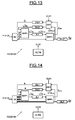
- turbo-code decoder FECD100 An example of such a turbo-code decoder FECD100 is illustrated in figure 13.
- the MAP1 unit comprises here four inputs instead of three as for the MAP1 unit of the turbo-code decoder FECD1 of figure 4.
- One input receives the systematic values.
- Another input receives the first parity values.
- Another input is connected to the output of the deinterleaving memory DIL1 for receiving the extrinsic values.
- the fourth input is connected to the output of the deinterleaving memory DIL2 for receiving the LLR2 values, i.e. the preceding decoding result stored in the deinterleaving memory DIL2.
- the other elements of the Turbo-code decoder FECD 100 are analogous to those of the Turbo-code decoder FECD1 of figure 4.
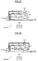
- x 1 , y 1 and y 2 represent respectively the systematic values, the first parity values and the second parity values of the first intermediate turbo-code encoded packet.
- the initial conditions are constituted by the systematic values x 1 , the first and second parity values y 1 and y 2 , the values "0" (figure 14) which represent the neutral values of the extrinsic information, as well as further values "0" which represent the neutral values of the LLR2 values.
- the input values from deinterleaver DIL1 and from deinterleaver DIL2 to the MAP 1 unit are set to "0".
- the calculated extrinsic information ⁇ 2 is used at the input of the MAP 1 unit (figure 15).
- the switch SW1 is positioned so that the deinterleaving memory DIL1 is connected between the extrinsic output of the MAP 2 unit and the a priori input of the MAP 1 unit.
- the LLR2 values (having here the constant values "0") are continuously fed to the fourth input of the MAP1 unit.
- ⁇ metrics are calculated by the MAP1 unit by using for example formulas (1) above.
- the LLR values LLR 2,int are delivered to the output deinterleaver DILT for obtaining the output data stream x est . Further, the control means CLTM send the control signal CLS1 so that these LLR values are also stored in the shadow memory DIL2 (figure 16).
- a negative acknowledgment is sent to the transmitter by the receiver and the transmitter will send additional symbols to increase the coding performance. This might be a complete packet or incremental information segments, depending on the used ARQ scheme.
- a second intermediate encoded packet is elaborated as described above for the first intermediate packet.
- x 1 , y 1 and y 2 represent respectively the systematic values, the first parity values and the second parity values of said second intermediate encoded packet.
- the initial conditions are constituted by the values x 1 , y 1 , y 2 and by the LLR values LLR 2 stored in the shadow memory DIL2 and related to the decoding of the first intermediate packet, as well as by the neutral values of the extrinsic data ⁇ 2 .
- the second intermediate packet is then turbo decoded as for the first intermediate packet (figure 18).
- the LLR2 values stored in the shadow memory DIL2 (having here constant values equal to the decoding result of the first intermediate packet) are continuously fed to the fourth input of the MAP1 unit.
- the LLR values (decoding results of the second intermediate packet) are stored in the shadow memory DIL2 in the eventuality of another ARQ iteration if the second intermediate packet has not been correctly decoded (figure 19).
- the turbo-code decoder FECD100 comprises several independent deinterleaver LLR memories, and one deinterleaver memory DIL1 for the extrinsic information.
- the FEC code used is a Low-Density Parity-Check code (LDPC code).
- LDPC code Low-Density Parity-Check code
- LDPC codes Low-Density Parity-Check (LDPC) codes were introduced by Gallager in 1962 and rediscovered in 1996 by MacKay and Neal. LDPC codes are also described for example in US 2003/0126551. For a long time they had no practical impact due to their computational and implementation complexity. This changed with advances in microelectronics that led to more computational power at hand for simulation and which now enables implementation. Due to their excellent error correction performance they are considered for future telecommunication standards.
- An LDPC code is a linear block code defined by its sparse M x N parity check matrix H. It contains j ones per column and k ones per row, called row and column degree respectively.
- a ( j,k )-regular LDPC code has row and column degree of uniform weight, otherwise the code is called irregular.
- a parity check code can be represented by a bipartite graph. The M check nodes correspond to the parity constraints, the N variable nodes represent the data symbols of the codeword. An edge in the graph corresponds to a one in the parity check matrix.
- the packet to encode of size ( N-M ) is multiplied with a generator matrix G of size (N-M) x N .
- This multiplication leads to an encoded vector of length N.
- FIG. 20 An example of such a structure of a LDPC code encoder FECC2 is illustrated in figure 20.
- the encoder FECC2 is to be used in a hybrid ARQ system with incremental redundancy, the encoder is further provided with a puncturing unit which delivers a punctured encoded codeword as explained above for the turbo-code encoder.
- puncturing unit may be used or not as explained above with reference to figure 2. But anyway, the same packet punctured (punctured encoded codeword) or not (encoded codeword) is retransmitted in the case of a negative acknowledgement.
- an LDPC code decoder comprises a decoding module which receives the encoded vector of length N and delivers an intermediate vector of length N by using the parity check matrix H. Then a demapping module extracts from said intermediate vector the decoded vector of length (N-M).
- the basic structure of an LDPC code decoder based on message passing concept consists of variable nodes and check nodes.
- An example of such a structure is depicted in figure 21.
- variable and check nodes represent the variable nodes connected to the input buffer IB of the decoder
- the references C1 to C3 are the check nodes.
- both variable and check nodes can be seen as processing units with dedicated memory elements.
- LDPC codes can be decoded using message passing algorithms, either in hard or soft decision form.
- the decoding is then an iterative process, which exchanges messages between variable and check nodes.
- BP Belief Propagation
- the LDPC code decoder FECD2 comprises also combination means located in particular within the variable nodes.
- the combination means will be used for elaborating the initial conditions of each ARQ iteration, and are controlled by control signal INS provided by control means CLTM.
- Each intermediate encoded packet obtained in a manner analogous to the one described for the turbo-decoding implementation of the invention, is stored in the input buffer IB (in this example the LLR of each input softbit, because we work here in the log domain).
- variable nodes Vi is equal to the number of data (bit) of the intermediate packet which is stored in the input buffer IB of size N.
- variable V1 connection between variable V1 and the check nodes C1-C3 is diagrammatically illustrated.
- variable node V1 sends message to the check node Ci by a link i and receives message from the check node Ci by a link i'.
- variable node V 1 receives also the bit IB 1 of the encoded intermediate packet stored in the input buffer IB.
- each check node comprises for example first storing means including first elementary output buffers (for example in particular VOBF1', VOBF2', VOBF3' for check nodes C1, C2, C3 respectively) whereas each variable node comprises second storing means including second elementary output buffers (for example in VOBF1, VOBF2, VOBF3).
- first elementary output buffers for example in particular VOBF1', VOBF2', VOBF3' for check nodes C1, C2, C3 respectively
- second storing means including second elementary output buffers for example in VOBF1, VOBF2, VOBF3
- the second elementary ouput buffer V0BF1 is connected to the input VIBF1 of the check node C1 by the link 1.
- the second elementary ouput buffer V0BF2 is connected to the input VIBF2 of the check node C2 by the link 2.
- the second elementary ouput buffer V0BF3 is connected to the input VIBF3 of the check node C3 by the link 3.
- the first elementary ouput buffer VOBF1' is connected to the input VIBF1' of the variable node V1 by the link 1'.
- the first elementary ouput buffer V0BF2' is connected to the input VIBF2' of the variable node V1 by the link 2'.
- the first elementary ouput buffer V0BF3' is connected to the input VIBF3' of the variable node V1 by the link 3'.
- processing unit of the variable node V1 comprises the combination means CMB, including here an adder (in case the implementation is in the log domain), as illustrated in figures 24-26.
- the adder is adapted to combine the input IB1 with the value at the input VIBF2' (i.e. with the content of the elementary ouput buffer VOBF2'), and with the value at the input VIBF3' (i.e. with the content of the elementary ouput buffer VOBF3'), and to store the summation result in the elementary buffer V0BF1, as illustrated in figure 24.
- the adder is further adapted to combine the input IB1 with the value at the input VIBF1' (i.e. with the content of the elementary ouput buffer VOBF1'), and with the value at the input VIBF3' (i.e. with the content of the elementary ouput buffer VOBF3'), and to store the summation result in the elementary buffer V0BF2, as illustrated in figure 25.
- the adder is further adapted to combine the input IB1 with the value at the input VIBF1' (i.e. with the content of the elementary ouput buffer VOBF1'), and with the value at the input VIBF2' (i.e. with the content of the elementary ouput buffer VOBF2'), and to store the summation result in the elementary buffer VOBF3, as illustrated in figure 26.
- the initial conditions are the N values of the first intermediate encoded packet stored in the input buffer IB.
- the LDPC decoding of the first intermediate packet can be processed by exchanging messages between the variables nodes and the check nodes, the corresponding adders of the variable nodes performing also summations according to summation schemes of the type illustrated in figures 24-26.
- the decoding results of this LDPC decoding are constituted with values which are stored in the first elementary ouput buffers of the check nodes Ci.
- the N respective values of the second intermediate packet, respectively stored in the input buffer IB are combined with the corresponding values contained in these first elementary ouput buffers of the check nodes Ci, in accordance with the connection scheme between the ckeck nodes and the variable nodes.
- the decoding result of the preceding decoding iteration is combined with the current intermediate packet.
- the LDPC decoding of the second intermediate packet is performed by exchanging again messages between the variable nodes and the check nodes.
- the LDPC decoder internal memory elements are used to store the intermediate decoding results for the use in the combination process. Instead of discarding the intermediate results and storing the original received soft values, theses results can be used in the consecutive decoding process.
- step 27 figure 2 when an intermediate packet has been considered to be correctly decoded (step 27 figure 2), the elementary output buffers of the check nodes are resetting to "zero" for the decoding of another incident encoded packet.
Landscapes
- Engineering & Computer Science (AREA)
- Computer Networks & Wireless Communication (AREA)
- Signal Processing (AREA)
- Error Detection And Correction (AREA)
Priority Applications (2)
| Application Number | Priority Date | Filing Date | Title |
|---|---|---|---|
| EP04028736A EP1667353A1 (fr) | 2004-12-03 | 2004-12-03 | Procédé et dispositif de décodage de paquets de données dans une procédure ARQ hybride |
| US11/293,460 US7600172B2 (en) | 2004-12-03 | 2005-12-02 | Method and device for decoding packets of data within a hybrid ARQ scheme |
Applications Claiming Priority (1)
| Application Number | Priority Date | Filing Date | Title |
|---|---|---|---|
| EP04028736A EP1667353A1 (fr) | 2004-12-03 | 2004-12-03 | Procédé et dispositif de décodage de paquets de données dans une procédure ARQ hybride |
Publications (1)
| Publication Number | Publication Date |
|---|---|
| EP1667353A1 true EP1667353A1 (fr) | 2006-06-07 |
Family
ID=34927649
Family Applications (1)
| Application Number | Title | Priority Date | Filing Date |
|---|---|---|---|
| EP04028736A Withdrawn EP1667353A1 (fr) | 2004-12-03 | 2004-12-03 | Procédé et dispositif de décodage de paquets de données dans une procédure ARQ hybride |
Country Status (2)
| Country | Link |
|---|---|
| US (1) | US7600172B2 (fr) |
| EP (1) | EP1667353A1 (fr) |
Families Citing this family (22)
| Publication number | Priority date | Publication date | Assignee | Title |
|---|---|---|---|---|
| CA2580280C (fr) | 2004-10-12 | 2015-03-10 | Aware, Inc. | Partage de ressources dans un environnement de telecommunications |
| US7571372B1 (en) | 2005-06-23 | 2009-08-04 | Marvell International Ltd. | Methods and algorithms for joint channel-code decoding of linear block codes |
| EP1811674A1 (fr) * | 2006-01-23 | 2007-07-25 | Motorola, Inc. | Appareil et procédé pour le décodage conjoint des messages sur la base des connaissances a priori de la transmission modifiée des mots de code |
| ATE526746T1 (de) * | 2006-03-03 | 2011-10-15 | Koninkl Philips Electronics Nv | Verfahren und vorrichtung zum übertragen und empfangen eines datenblocks in einem drahtlosen kommunikationssystem |
| US8213548B2 (en) * | 2006-04-04 | 2012-07-03 | Qualcomm Incorporated | Methods and apparatus for dynamic packet reordering |
| US8139612B2 (en) * | 2006-04-04 | 2012-03-20 | Qualcomm Incorporated | Methods and apparatus for dynamic packet mapping |
| EP3866416B1 (fr) | 2006-04-12 | 2023-08-23 | TQ Delta, LLC | Procedé et dispositif pour la retransmission de paquets et le partage de mémoire |
| US8028216B1 (en) | 2006-06-02 | 2011-09-27 | Marvell International Ltd. | Embedded parity coding for data storage |
| JPWO2008093717A1 (ja) * | 2007-01-31 | 2010-05-20 | パナソニック株式会社 | 無線通信装置およびパンクチャリング方法 |
| US8332718B2 (en) | 2007-03-29 | 2012-12-11 | Sirius Xm Radio Inc. | Efficient implementation to perform iterative decoding with large iteration counts |
| US8189581B2 (en) * | 2007-06-20 | 2012-05-29 | Motorola Mobility, Inc. | Method, signal and apparatus for managing the transmission and receipt of broadcast channel information |
| US8151158B2 (en) * | 2007-08-15 | 2012-04-03 | Broadcom Corporation | Method and system for decoding a data burst in a communication system |
| US8181081B1 (en) | 2007-11-30 | 2012-05-15 | Marvell International Ltd. | System and method for decoding correlated data |
| US8209590B2 (en) * | 2008-11-05 | 2012-06-26 | Broadcom Corporation | Header encoding/decoding |
| US20100299579A1 (en) * | 2009-05-21 | 2010-11-25 | Ternarylogic Llc | Methods and Systems for Error-Correction in Convolutional and Systematic Convolutional Decoders in Galois Configuration |
| US9954643B2 (en) * | 2012-06-22 | 2018-04-24 | Samsung Electronics Co., Ltd. | Communication system with repeat-response combining mechanism and method of operation thereof |
| US9059742B1 (en) | 2013-03-15 | 2015-06-16 | Western Digital Technologies, Inc. | System and method for dynamic scaling of LDPC decoder in a solid state drive |
| KR20150024489A (ko) * | 2013-08-26 | 2015-03-09 | 삼성전자주식회사 | 메모리 시스템에서의 ldpc 디코딩 방법 및 이를 이용한 ldpc 디코더 |
| KR102080069B1 (ko) * | 2013-09-25 | 2020-04-14 | 삼성전자주식회사 | 비이진 ldpc 부호를 사용하는 수신기에서 데이터를 복호하는 방법 및 장치 |
| GB2525877B (en) * | 2014-05-07 | 2016-08-10 | Cisco Tech Inc | Forward error correction with turbo/non-turbo switching |
| WO2020069635A1 (fr) * | 2018-10-03 | 2020-04-09 | Qualcomm Incorporated | Ensembles de ponctionnement équivalents pour retransmissions codées polaires |
| US12267173B2 (en) * | 2019-10-18 | 2025-04-01 | Samsung Electronics Co., Ltd. | Method and apparatus for enabling optimized decoding of data packet in HARQ based communication |
Family Cites Families (6)
| Publication number | Priority date | Publication date | Assignee | Title |
|---|---|---|---|---|
| US6314535B1 (en) * | 1999-05-18 | 2001-11-06 | Xircom Wireless, Inc. | Dynamic forward error correction |
| US6650949B1 (en) * | 1999-12-30 | 2003-11-18 | General Electric Company | Method and system for sorting incident log data from a plurality of machines |
| US6847760B2 (en) * | 2001-10-23 | 2005-01-25 | Georgia Tech Research Corporation | Spatially resolved equalization and forward error correction for multimode fiber links |
| KR100584170B1 (ko) * | 2002-07-11 | 2006-06-02 | 재단법인서울대학교산학협력재단 | 터보 부호화된 복합 재전송 방식 시스템 및 오류 검출 방법 |
| ATE521144T1 (de) * | 2002-09-10 | 2011-09-15 | Ericsson Telefon Ab L M | Systeme für schutzverbindungsüberwachung |
| EP1528702B1 (fr) * | 2003-11-03 | 2008-01-23 | Broadcom Corporation | Décodage de code de correction d'erreurs en avant (FEC) avec paramètres dynamiques |
-
2004
- 2004-12-03 EP EP04028736A patent/EP1667353A1/fr not_active Withdrawn
-
2005
- 2005-12-02 US US11/293,460 patent/US7600172B2/en active Active
Non-Patent Citations (4)
| Title |
|---|
| CHITI F ET AL: "Soft combining hybrid ARQ schemes application to reliable communications within 3G wireless networks", WIRELESS COMMUNICATIONS AND NETWORKING, 2003. WCNC 2003. 2003 IEEE 16-20 MARCH 2003, PISCATAWAY, NJ, USA,IEEE, vol. 3, 16 March 2003 (2003-03-16), pages 1779 - 1783, XP010640039, ISBN: 0-7803-7700-1 * |
| NARAYANAN K R ET AL: "A NOVEL ARQ TECHNIQUE USING THE TURBO CODING PRINCPIPLE", IEEE COMMUNICATIONS LETTERS, IEEE SERVICE CENTER, PISCATAWAY,US, US, vol. 1, no. 2, March 1997 (1997-03-01), pages 49 - 51, XP000687091, ISSN: 1089-7798 * |
| NAROSKA E ET AL: "A novel type-II hybrid ARQ scheme", EMERGING TECHNOLOGIES: FRONTIERS OF MOBILE AND WIRELESS COMMUNICATION, 2004. PROCEEDINGS OF THE IEEE 6TH CIRCUITS AND SYSTEMS SYMPOSIUM ON SHANGHAI, CHINA MAY 31-JUNE 2, 2004, PISCATAWAY, NJ, USA,IEEE, vol. 1, 31 May 2004 (2004-05-31), pages 85 - 88, XP010716019, ISBN: 0-7803-7938-1 * |
| UHLEMANN E ET AL: "Packet combining and doping in concatenated hybrid ARQ schemes using iterative decoding", WIRELESS COMMUNICATIONS AND NETWORKING, 2003. WCNC 2003. 2003 IEEE 16-20 MARCH 2003, PISCATAWAY, NJ, USA,IEEE, vol. 2, 16 March 2003 (2003-03-16), pages 849 - 854, XP010639878, ISBN: 0-7803-7700-1 * |
Also Published As
| Publication number | Publication date |
|---|---|
| US7600172B2 (en) | 2009-10-06 |
| US20060156163A1 (en) | 2006-07-13 |
Similar Documents
| Publication | Publication Date | Title |
|---|---|---|
| US7600172B2 (en) | Method and device for decoding packets of data within a hybrid ARQ scheme | |
| US8656247B2 (en) | Apparatus and method for encoding and decoding block low density parity check codes with a variable coding rate | |
| CN1155160C (zh) | 发送和接收链接码数据的方法和装置 | |
| EP1193881B1 (fr) | Retransmission automatique ARQ pour données turbo-codées | |
| EP1240715B1 (fr) | Systeme et procede hybride a demande automatique de repetition | |
| US7093180B2 (en) | Fast H-ARQ acknowledgement generation method using a stopping rule for turbo decoding | |
| US20050149841A1 (en) | Channel coding/decoding apparatus and method using a parallel concatenated low density parity check code | |
| US7992073B2 (en) | Decoding device, decoding method, and receiving apparatus | |
| WO2002078196A1 (fr) | Procede et element de codage pour correction d'erreurs utilisant une parite concatenee et des codes turbo | |
| US20060190801A1 (en) | Apparatus and method for generating low density parity check code using zigzag code in a communication system | |
| KR20040006171A (ko) | 터보 부호화된 복합 재전송 방식 시스템 및 오류 검출 방법 | |
| CN103490866B (zh) | 星地传输网络中基于网络编码的harq传输方法 | |
| WO2002087088A2 (fr) | Procedes et dispositifs permettant la combinaison de demodulations de signaux avec differentes modulations et le codage pour des communications hertziennes | |
| US8358713B2 (en) | High throughput and low latency map decoder | |
| Roongta et al. | Reliability-based hybrid ARQ using convolutional codes | |
| CN101069357B (zh) | 对数据块冗余版本进行解码的Turbo解码器 | |
| Zaitsev et al. | Structural adaptation of the turbo code coder and decoder for generating the transmission repeat request under conditions of uncertainty | |
| Wang et al. | A design of hybrid automatic repeat request scheme based on systematic polar codes | |
| Yatribi et al. | Hybrid automatic repeat request protocols: Turbo-Codes against Cyclic Binary low-density parity-check codes | |
| Ayoub et al. | Hybrid-ARQ Protocols using Iterative Threshold Decoding of OSMLD Product Codes | |
| EP1447936A1 (fr) | Unité de communication de données et procédé correspondant pour un décodage itératif | |
| Xia et al. | An efficient type-II hybrid ARQ protocol using Reed-Solomon codes | |
| Kim et al. | Bit-level hybrid-ARQ schemes with turbo codes | |
| Sahib | DESIGN OF TURBO DECODER MODEL USING MAP AND SOFT-INPUT SOFT-OUTPUT VERTIBI ALGORITHM FOR AWGN AND RAYLEIGH CHANNELS | |
| KR20070069481A (ko) | 광대역 무선 접속 통신 시스템에서 복호 방법 및 장치 |
Legal Events
| Date | Code | Title | Description |
|---|---|---|---|
| PUAI | Public reference made under article 153(3) epc to a published international application that has entered the european phase |
Free format text: ORIGINAL CODE: 0009012 |
|
| AK | Designated contracting states |
Kind code of ref document: A1 Designated state(s): AT BE BG CH CY CZ DE DK EE ES FI FR GB GR HU IE IS IT LI LT LU MC NL PL PT RO SE SI SK TR |
|
| AX | Request for extension of the european patent |
Extension state: AL BA HR LV MK YU |
|
| 17P | Request for examination filed |
Effective date: 20061130 |
|
| 17Q | First examination report despatched |
Effective date: 20070103 |
|
| AKX | Designation fees paid |
Designated state(s): DE FR GB IT |
|
| STAA | Information on the status of an ep patent application or granted ep patent |
Free format text: STATUS: THE APPLICATION IS DEEMED TO BE WITHDRAWN |
|
| 18D | Application deemed to be withdrawn |
Effective date: 20070714 |