EP1667838B1 - Crimp-free infusible reinforcement fabric and method for its manufacture - Google Patents
Crimp-free infusible reinforcement fabric and method for its manufacture Download PDFInfo
- Publication number
- EP1667838B1 EP1667838B1 EP04783721A EP04783721A EP1667838B1 EP 1667838 B1 EP1667838 B1 EP 1667838B1 EP 04783721 A EP04783721 A EP 04783721A EP 04783721 A EP04783721 A EP 04783721A EP 1667838 B1 EP1667838 B1 EP 1667838B1
- Authority
- EP
- European Patent Office
- Prior art keywords
- fabric
- tows
- tow
- tow groups
- groups
- Prior art date
- Legal status (The legal status is an assumption and is not a legal conclusion. Google has not performed a legal analysis and makes no representation as to the accuracy of the status listed.)
- Expired - Lifetime
Links
Images


Classifications
-
- B—PERFORMING OPERATIONS; TRANSPORTING
- B29—WORKING OF PLASTICS; WORKING OF SUBSTANCES IN A PLASTIC STATE IN GENERAL
- B29C—SHAPING OR JOINING OF PLASTICS; SHAPING OF MATERIAL IN A PLASTIC STATE, NOT OTHERWISE PROVIDED FOR; AFTER-TREATMENT OF THE SHAPED PRODUCTS, e.g. REPAIRING
- B29C70/00—Shaping composites, i.e. plastics material comprising reinforcements, fillers or preformed parts, e.g. inserts
- B29C70/04—Shaping composites, i.e. plastics material comprising reinforcements, fillers or preformed parts, e.g. inserts comprising reinforcements only, e.g. self-reinforcing plastics
- B29C70/06—Fibrous reinforcements only
- B29C70/10—Fibrous reinforcements only characterised by the structure of fibrous reinforcements, e.g. hollow fibres
- B29C70/16—Fibrous reinforcements only characterised by the structure of fibrous reinforcements, e.g. hollow fibres using fibres of substantial or continuous length
- B29C70/22—Fibrous reinforcements only characterised by the structure of fibrous reinforcements, e.g. hollow fibres using fibres of substantial or continuous length oriented in at least two directions forming a two-dimensional [2D] structure
-
- B—PERFORMING OPERATIONS; TRANSPORTING
- B29—WORKING OF PLASTICS; WORKING OF SUBSTANCES IN A PLASTIC STATE IN GENERAL
- B29C—SHAPING OR JOINING OF PLASTICS; SHAPING OF MATERIAL IN A PLASTIC STATE, NOT OTHERWISE PROVIDED FOR; AFTER-TREATMENT OF THE SHAPED PRODUCTS, e.g. REPAIRING
- B29C70/00—Shaping composites, i.e. plastics material comprising reinforcements, fillers or preformed parts, e.g. inserts
- B29C70/04—Shaping composites, i.e. plastics material comprising reinforcements, fillers or preformed parts, e.g. inserts comprising reinforcements only, e.g. self-reinforcing plastics
- B29C70/06—Fibrous reinforcements only
- B29C70/10—Fibrous reinforcements only characterised by the structure of fibrous reinforcements, e.g. hollow fibres
- B29C70/16—Fibrous reinforcements only characterised by the structure of fibrous reinforcements, e.g. hollow fibres using fibres of substantial or continuous length
- B29C70/22—Fibrous reinforcements only characterised by the structure of fibrous reinforcements, e.g. hollow fibres using fibres of substantial or continuous length oriented in at least two directions forming a two-dimensional [2D] structure
- B29C70/226—Fibrous reinforcements only characterised by the structure of fibrous reinforcements, e.g. hollow fibres using fibres of substantial or continuous length oriented in at least two directions forming a two-dimensional [2D] structure the structure comprising mainly parallel filaments interconnected by a small number of cross threads
-
- B—PERFORMING OPERATIONS; TRANSPORTING
- B29—WORKING OF PLASTICS; WORKING OF SUBSTANCES IN A PLASTIC STATE IN GENERAL
- B29C—SHAPING OR JOINING OF PLASTICS; SHAPING OF MATERIAL IN A PLASTIC STATE, NOT OTHERWISE PROVIDED FOR; AFTER-TREATMENT OF THE SHAPED PRODUCTS, e.g. REPAIRING
- B29C70/00—Shaping composites, i.e. plastics material comprising reinforcements, fillers or preformed parts, e.g. inserts
- B29C70/04—Shaping composites, i.e. plastics material comprising reinforcements, fillers or preformed parts, e.g. inserts comprising reinforcements only, e.g. self-reinforcing plastics
- B29C70/28—Shaping operations therefor
- B29C70/54—Component parts, details or accessories; Auxiliary operations, e.g. feeding or storage of prepregs or SMC after impregnation or during ageing
-
- B—PERFORMING OPERATIONS; TRANSPORTING
- B32—LAYERED PRODUCTS
- B32B—LAYERED PRODUCTS, i.e. PRODUCTS BUILT-UP OF STRATA OF FLAT OR NON-FLAT, e.g. CELLULAR OR HONEYCOMB, FORM
- B32B3/00—Layered products comprising a layer with external or internal discontinuities or unevennesses, or a layer of non-planar shape; Layered products comprising a layer having particular features of form
Definitions
- This invention relates to composite fabrics and to a method of making composite fabrics. More particularly, it relates to an improved composite fabric having flow channels, which, when resin is applied to the fabric during lamination, permit faster resin distribution in the fabric.
- Composite fabrics made from fibrous materials formed into both woven, knitted and non-woven material, are well-known in the art. Yarns of glass, carbon and graphite are typically formed into fabrics, and a plurality of layers of fabric are stacked and cut into dry fabric preforms. The preforms are then stitched and/or impregnated with a resin binder to form a rigid composite fabric.
- a glass reinforced fibrous mat is preformed and then placed in a mold for molding into a fiber-reinforced article.
- Glass fiber-reinforcement mats are used in situations where a desired strength is necessary, such as in boat hulls or automobile parts.
- layers of the continuous strand mat and layers of unidirectional or multidirectional reinforcement material are fabricated separately. These layers are individually placed in a set of preform screens, which generally consist of an upper screen and a lower screen. The upper and lower screens are moved together in order to conform the layers to the shape of the preform screens. The layers are thus shaped into what is known as a preform.
- the preform is then placed in a mold and injected with a suitable resinous material to make the fiber-reinforced article.
- holes are typically punched in the fabric as two or more layers of fabric are sewn together.
- the holes extend through the fabric and when the fabric is impregnated with resin, the resin material flows into the holes in the blanket.
- the holes in the fabric aid in distributing resin throughout the fabric.
- U.S. Patent 4,615,934 teaches a fabric having warp yarns of heavy denier separated by eight warp yarns of lighter denier. The fabric is incorporated into a polymeric resin by lamination, heat bonding or coating the fabric with the resin. U.S. 5,147,714 (related to 4,615,934 ) utilizes this same concept of alternating heavier and lighter denier yarns however the fabric is laminated between two conductive sheets of PVC film.
- U.S. 4,460,633 teaches a non-woven reinforcement constructed of high denier warps of non-twist yarns or soft twist yarns on both sides of lower denier wefts of non-twist yarns or soft twist yarns containing an adhesive agent, in which the warps and wefts are bonded where they intersect.
- U.S. 4,407,885 and U.S. 4,410,385 teach a composite non-woven fabric and a method of making the composite fabric in which the layers of the fabric are impregnated with a resin binder to form a rigid composite fabric.
- Thermosplastic fibrous material is incorporated within the structure of non-woven layers.
- a plurality of layers of fabric are stacked adjacent each other to provide a preform assembly. The layers are then compacted and heated to promote the bonding of the thermoplastic material at junctures between the fibrous non-woven material.
- U.S. 5,085,928 teaches porous layers of unidirectional aramid fibers alternated with porous layers of spunlaced nonwoven aramid fibers all of which are embedded in a thermoplastic resin.
- U.S. 5,809,805 teaches a warp/knit stich reinforced multi-axial non-crimp layered fabric sheet.
- the fabric is comprised of a plurality of plies, which have a different angular relationship to one another, disposed upon one another and knitted or stiched to form a structural sheet. The sheet is then impgrenated with a resin.
- U.S. 5,445,693 and related U.S. 5,055,242 teach a formable composite material having a plurality of superimposed layers each having having a plurality of unidirectional non-woven yarns or threads laid side-by-side. Some of the yarns or thread extend of different layers extend in different directions. The layers are incorporated with a resin material prior to being stiched together.
- U.S. 5,149,583 teaches a mat in which reinforcing threads are bound or laminated to form a strong shell structure.
- the knitting of the mat is performed with a double circular knitting machine to form a weft-knitted mat.
- the fabric contains a plurality of loops in which reinforcing threads run with the support of the loops and straight between the courses in a channel formed by the loops.
- EP 0 909 845 discloses a woven carbon fabric comprising parallel and uniformly spaced carbon fiber warp yarns and auxiliary yarns in the weft direction and a method of making such a fabric in accordance with the preambles of claims 1 and 17 respectively.
- EP 1 419 875 discloses a reinforcing fiber substrate comprising parallel reinforcing fiber yarns spaced apart by spacer yarns.
- the present invention relates to a composite fabric as defined in claim 1 and a method as defined in claim 17 wherein a plurality of substantially parallel, coaxially aligned tow groups, each of said tow group having one or more tows wherein a portion of said tow groups contain two or more tows.
- the spacing between tows in a tow group is less than the spacing between adjacent tow groups.
- the spacing between adjacent tow groups forms flow channels.
- the flow channels permit resin to flow evenly and quickly through the fabric, which results in shorter processing time and a more consistent resin distribution, decreasing the likelihood of resin starved areas within the cured laminate.
- the spacing between tows in a tow group is less than the spacing between adjacent tow groups.
- the spacing between adjacent tow groups forms flow channels.
- the flow channels can be formed in a single ply in a fabric or in any number of plies in a multi-ply fabric. When the fabric is infused with resin, the flow channels permit faster resin infusion of the fabric (typically between about 40% to about 60%).
- the term “tow” refers to an untwisted assembly of a large number of filaments (single fibers).
- the term “tow group” refers to one or more tows that are closely spaced.
- Fabric 2 is made of a plurality of substantially parallel, coaxially aligned tows 4 which comprise adjacent tow groups 5, 7.
- tow group 5 contains two tows and tow group 7 contains three tows.
- the tow groups in fabric 2 are intermittently spaced, the spaces between the tow groups forming flow channels 6.
- the placement of flow channels between tow groups may vary, that is, one tow group, having two adjacent tows, between a tow group, having four adjacent tows, and equally spacing tow groups.
- the ratio of tow groups to flow channels may be determined by the resin, that is, a more viscous resin would require equally alternating tow groups to flow channels, thus providing more channels for the flow of the resin. In the alternative, a less viscous resin would require less flow channels.
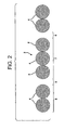
- Fig. 2 illustrates a cross-sectional view of the fabric 2 of Fig. 1 showing tow groups 5, 7, containing tow 4. Tow groups 5, 7 are spaced so as to form flow channels 6.
- Fig. 1 illustrates the tows 4, in tow group 5, as abutting one another.
- the tow in the tow groups may be spaced so long as the distance between the tows is less than that of the distance between the tow groups forming the flow channel.
- the size of the flow channel is typically between about 0.155 to about 1.28 centimeters.
- tows 4 have a yield (yards/pound (meter/kilogram)) of between about 52 (104.83) to about 450 (907.16) yield, more preferably of between about 150 (302.38) to about 350 (705.57) yield and most preferably between about 150 (302.38) to about 220 (443.50) yield.
- the present invention is compatible with various different glass fiber-reinforcements.
- Any suitable unidirectional or multidirectional reinforcement materials can be employed. It is within the contemplated scope of this invention that such unidirectional or multidirectional reinforcement material include, but not be limited to, such materials as, for example, chopped strand mat, knitted rovings or woven rovings, aramid reinforcements or carbon reinforcements.
- Unidirectional knitted rovings are normally comprised of E-glass rovings, (such as rovings of 300 yield (604,77)), for example, rovings known as T30 from Owens Corning). Bidirectional knitted roving material is constructed by a precision knitting process.
- the fiberglass strands are typically treated with a binder or sizing (such as Owens Corning 111A and PPG 2022), a wetting agent, emulsifying agent and water. These sizes or binders are intended to protect the fibers from damage during their formation and subsequent operations of twisting, plying and weaving.
- a binder or sizing such as Owens Corning 111A and PPG 2022
- the fabric of the present invention may be constructed of woven, knitted or non-woven fibers, yarns, threads, filaments and the like.
- the structural fibrous materials may be any well-known materials which form fibers, filaments, threads, yarns, woven fabrics, knitted fabrics, non-woven fabrics, batts, felts, and the like.
- structural fibrous material embraces all of the various types of materials, which form such fabrics useful to form a composite fabric in accordance with the present invention.
- Exemplary structural fibrous materials include glass in the form of glass fibers, carbon or graphite in the form of carbon or graphite fibers, non-graphite carbon fibers, vitreous carbon fibers, boron monolithic graphite and monolithic non-graphite carbon fibers, silicon, aramid and other refractory materials.
- thermoplastic fibrous material may also be used.
- the fabric may also be a hybrid fabric, having more than one type of structural fiber in its construction, that is, glass/thermoplastic, aramid/glass, and other combinations such as combination of the materials listed above.
- Figs. 1-2 depict a unidirectional fiber orientation of the fabric 2.
- the fibers are crimp-free warp knitted fabrics otherwise know as stitch-bonded fabrics.
- the fabric 2 of the present invention is a corrugated fabric, which is essentially crimp-free as a result of the flow channels 6.
- the fabric 2 of the present invention is stitch-bonded using conventional stitch-bonding techniques and styles, that is, chain, tricot, modified tricot, promat). Conventional machines known in the art such as a Liba stitch-bonding machine are used to make the fabric of the present invention.
- the structure of the fabric of the present invention may also be bi-axial, tri-axial, quadaxial or multiaxial fabric structures.
- Conventional fabrics are made by weaving fibers in two perpendicular directions (warp and weft). Weaving, though, bends the fibers, reducing the maximum strength and stiffness that can be attained.
- Typical stitch-bonded, multiaxial fabrics consist of several layers of unidirectional fiber bundles or tows held together by a non-structural stitching thread (usually polyester).
- the tows in each layer can be input at almost any angle between 0° and 90°.
- the entire fabric may be made of a single material, or different materials can be used in each layer for a hybrid fabric.
- Fig. 3 illustrates biaxial fabric 8 of the present disclosure.
- Fabric 8 contains layers 16 and 18.
- Layer 16 has tow groups 12, 14 spaced between flow channels 26, 28, 30 and layer 18 has tow groups 20, 22 spaced between flow channels 32, 34, 36.
- the tow groups in layer 16 of biaxial fabric 8 lie at a 90° angle and the tow groups in layer 18 lie at a 0° angle which is a conventional biaxial fabric structure as is known in the art.
- Fig. 4 illustrates triaxial fabric 38 of the present disclosure.
- Fabric 38 contains layers 40, 42 and 44.
- Layer 40 has tow groups 46, 48 spaced between flow channels 50, 52 and 54
- layer 42 has tow groups 56, 58 spaced between flow channels 60, 62 and 64
- layer 44 has tow groups 53, 55 spaced between flow channels 57, 59 and 61.
- the tow groups in layer 40 of triaxial fabric 38 lie at a 90° angle
- the tow groups in layer 42 lie at a -45° angle
- the tow groups in layer 44 lie at a 0° angle which is typical construction of a triaxial fabric as is known in the art.
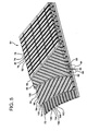
- Fig. 5 illustrates quadaxial fabric 64 having layers 66, 68, 70 and 72.
- Layer 66 has tow groups 74, 76 and 78 spaced between flow channels 78, 80 and 82
- layer 68 has tow groups 84, 86 spaced between flow channels 88, 90 and 92
- layer 70 has tows groups 94, 96 spaced between flow channels 98, 100 and 102
- layer 72 has tow groups 104, 106 spaced between flow channels 108, 110 and 112.
- Fig. 5 illustrates quadaxial fabric 64 having layers 66, 68, 70 and 72.
- the tow groups in layer 66 of triaxial fabric 64 lie at a 90° angle
- the tow groups in layer 68 lie at a -45° angle
- the tow groups inn layer 70 lie at a +45° angle
- the tow groups in layer 72 lie at a 0° angle.
- any combination of angles may be used depending on the application of the fabric.
- the fabrics of the present invention may be engineered to meet specific requirements and support multiple tasks according to the application of the fabric, that is, automotive parts, etc.
- the fabric of the present invention is particularly useful in molding processes where resin must move through a fabric to create a consolidated composite.
- resin transfer molding RTM
- Resin transfer molding RTM is a process by which a resin is pumped at low viscosities and low pressures into a closed mold die set containing a preform of dry fabric, that is, fabric 2, to infuse resin into the preform and to make a fiber-reinforced composite part.
- the RTM process can be used to produce at low cost composite parts that are complex in shape. These parts typically require continuous fiber reinforcement along with inside mold line and outside mold line controlled surfaces. The ability to include and place continuous fiber reinforcement in large and small structures sets RTM apart from other liquid molding processes.
- Fabric 2 is also useful in a vacuum assisted resin transfer molding (VARTM) system. In VARTM, the preform is covered by a flexible sheet or liner, such as fabric 2.
- VARTM vacuum assisted resin transfer molding
- the flexible sheet or liner is clamped onto the mold to seal the preform in an envelope.
- a catalyzed matrix resin is then introduced into the envelope to wet the preform.
- a vacuum is applied to the interior of the envelope via a vacuum line to collapse the flexible sheet against the preform.
- the vacuum draws the resin through the preform and helps to avoid the formation of air bubbles or voids in the finished article.
- the matrix resin cures while being subjected to the vacuum.
- the application of the vacuum draws off any fumes produced during the curing process.
- the fabric 2 of the present invention is useful in standard vacuum infusion molding processes as well as process where the reinforced fabric is under vacuum.
- thermoplastic resins useful with the present invention in the above molding processes include polyesters (including copolyesters), for example, polyethylene terephthalate, polyamides, polyolefins, and polypropylene.
- Thermosetting resins that are useful include phenolic resins, epoxy resins, vinyl ester resins, and thermosetting polyester resins.
Landscapes
- Engineering & Computer Science (AREA)
- Textile Engineering (AREA)
- Chemical & Material Sciences (AREA)
- Composite Materials (AREA)
- Mechanical Engineering (AREA)
- Reinforced Plastic Materials (AREA)
- Woven Fabrics (AREA)
- Laminated Bodies (AREA)
Abstract
Description
- This invention relates to composite fabrics and to a method of making composite fabrics. More particularly, it relates to an improved composite fabric having flow channels, which, when resin is applied to the fabric during lamination, permit faster resin distribution in the fabric.
- Composite fabrics made from fibrous materials formed into both woven, knitted and non-woven material, are well-known in the art. Yarns of glass, carbon and graphite are typically formed into fabrics, and a plurality of layers of fabric are stacked and cut into dry fabric preforms. The preforms are then stitched and/or impregnated with a resin binder to form a rigid composite fabric.
- Typically, a glass reinforced fibrous mat is preformed and then placed in a mold for molding into a fiber-reinforced article. Glass fiber-reinforcement mats are used in situations where a desired strength is necessary, such as in boat hulls or automobile parts. For example, layers of the continuous strand mat and layers of unidirectional or multidirectional reinforcement material are fabricated separately. These layers are individually placed in a set of preform screens, which generally consist of an upper screen and a lower screen. The upper and lower screens are moved together in order to conform the layers to the shape of the preform screens. The layers are thus shaped into what is known as a preform. The preform is then placed in a mold and injected with a suitable resinous material to make the fiber-reinforced article.
- As shown in
U.S. 4,911,973 , to facilitate impregnation of the fabric with resin, holes are typically punched in the fabric as two or more layers of fabric are sewn together. The holes extend through the fabric and when the fabric is impregnated with resin, the resin material flows into the holes in the blanket. The holes in the fabric aid in distributing resin throughout the fabric. - The crimping of the yarns that occurs as the warp and weft yarns cross over and under each other reduces the tensile and, more significantly, the compressive strength of a woven fabric. In the past, fabrics have been designed utilizing yarns having varying denier (fiber diameter) to increase strength and reduce crimping of the fabric.
-
U.S. Patent 4,615,934 teaches a fabric having warp yarns of heavy denier separated by eight warp yarns of lighter denier. The fabric is incorporated into a polymeric resin by lamination, heat bonding or coating the fabric with the resin.U.S. 5,147,714 (related to4,615,934 ) utilizes this same concept of alternating heavier and lighter denier yarns however the fabric is laminated between two conductive sheets of PVC film. -
U.S. 4,460,633 teaches a non-woven reinforcement constructed of high denier warps of non-twist yarns or soft twist yarns on both sides of lower denier wefts of non-twist yarns or soft twist yarns containing an adhesive agent, in which the warps and wefts are bonded where they intersect. -
U.S. 4,407,885 andU.S. 4,410,385 (related) teach a composite non-woven fabric and a method of making the composite fabric in which the layers of the fabric are impregnated with a resin binder to form a rigid composite fabric. Thermosplastic fibrous material is incorporated within the structure of non-woven layers. A plurality of layers of fabric are stacked adjacent each other to provide a preform assembly. The layers are then compacted and heated to promote the bonding of the thermoplastic material at junctures between the fibrous non-woven material. -
U.S. 5,085,928 teaches porous layers of unidirectional aramid fibers alternated with porous layers of spunlaced nonwoven aramid fibers all of which are embedded in a thermoplastic resin. -
U.S. 5,809,805 teaches a warp/knit stich reinforced multi-axial non-crimp layered fabric sheet. The fabric is comprised of a plurality of plies, which have a different angular relationship to one another, disposed upon one another and knitted or stiched to form a structural sheet. The sheet is then impgrenated with a resin. -
U.S. 5,445,693 and relatedU.S. 5,055,242 teach a formable composite material having a plurality of superimposed layers each having having a plurality of unidirectional non-woven yarns or threads laid side-by-side. Some of the yarns or thread extend of different layers extend in different directions. The layers are incorporated with a resin material prior to being stiched together. -
U.S. 5,149,583 teaches a mat in which reinforcing threads are bound or laminated to form a strong shell structure. The knitting of the mat is performed with a double circular knitting machine to form a weft-knitted mat. The fabric contains a plurality of loops in which reinforcing threads run with the support of the loops and straight between the courses in a channel formed by the loops. -
EP 0 909 845 discloses a woven carbon fabric comprising parallel and uniformly spaced carbon fiber warp yarns and auxiliary yarns in the weft direction and a method of making such a fabric in accordance with the preambles of claims 1 and 17 respectively.EP 1 419 875 discloses a reinforcing fiber substrate comprising parallel reinforcing fiber yarns spaced apart by spacer yarns. - As taught above, it is known to have heavy denier warp yarns separated from each other by lighter denier warp yarns in a warp-inserted weft knit fabric. Also, using sewing needles to form a plurality of channels in a reinforcement blanket to aid in distributing resin throughout the blanket is known. Both methods permit resin to be distributed throughout the fabric.
- There is a need to provide a fabric, having continuous fibers, to be used in a molding process, in which the design of the fabric increases the speed of resin infusion to reduce processing time in the mold.
- The foregoing and other advantages of the invention will become apparent from the following disclosure in which one or more preferred embodiments of the invention are described in detail and illustrated in the accompanying drawings. It is contemplated that variations in procedures, structural features and arrangement of parts may appear to a person skilled in the art without departing from the scope of or sacrificing any of the advantages of the invention.
- The present invention relates to a composite fabric as defined in claim 1 and a method as defined in claim 17 wherein a plurality of substantially parallel, coaxially aligned tow groups, each of said tow group having one or more tows wherein a portion of said tow groups contain two or more tows. The spacing between tows in a tow group is less than the spacing between adjacent tow groups. The spacing between adjacent tow groups forms flow channels. The flow channels permit resin to flow evenly and quickly through the fabric, which results in shorter processing time and a more consistent resin distribution, decreasing the likelihood of resin starved areas within the cured laminate.
- It is an object of this invention to provide a crimp-free composite fabric.
- It is an object of this invention to provide a composite fabric, which is designed to decrease the processing time of resin infusion.
- It is an object of this invention to provide a composite fabric that is usable with all types of resin systems.
- It is an object of this invention to provide a composite fabric which can be constructed of various types of fibers.
- It is an object of this invention to provide a fabric which is constructed of various composite materials, that is, glass and thermoplastic.
-
-
Fig. 1 is a fragmentary, perspective view of a preferred fabric configuration of the present invention. -
Fig. 2 is a cross-sectional view of a preferred fabric configuration of the present invention. -
Fig. 3 is a partially sectional perspective view showing a biaxial fabric of the present disclosure. -
Fig. 4 is a partially sectional perspective view showing a triaxial fabric of the present disclosure. -
Fig. 5 is a partially sectional perspective view showing a quadaxial fabric of the present disclosure. - In describing preferred embodiments of the invention, which are illustrated in the drawings, specific terminology is resorted to for the sake of clarity. However, it is not intended that the invention be limited to the specific terms so selected and it is to be understood that each specific term includes all technical equivalents that operate in a similar manner to accomplish a similar purpose.
- Although preferred embodiments of the invention are herein described, it is understood that various changes and modifications in the illustrated and described structure can be affected without departure from the basic principles that underlie the invention. Changes and modifications of this type are therefore deemed to be circumscribed by the spirit and scope of the invention, except as the same may be necessarily modified by the appended claims or reasonable equivalents thereof.
- The above objects have been achieved through the development of a fabric as defined in claim 1.
- The spacing between tows in a tow group is less than the spacing between adjacent tow groups. The spacing between adjacent tow groups forms flow channels. The flow channels can be formed in a single ply in a fabric or in any number of plies in a multi-ply fabric. When the fabric is infused with resin, the flow channels permit faster resin infusion of the fabric (typically between about 40% to about 60%).
- For the purposes of this invention, the term "tow" refers to an untwisted assembly of a large number of filaments (single fibers). The term "tow group" refers to one or more tows that are closely spaced.
- Referring to
Fig. 1 , a fragmentary, perspective view of the fabric of the present invention is shown.Fabric 2 is made of a plurality of substantially parallel, coaxially alignedtows 4 which compriseadjacent tow groups Fig.1 ,tow group 5 contains two tows andtow group 7 contains three tows. The tow groups infabric 2 are intermittently spaced, the spaces between the tow groups formingflow channels 6. The placement of flow channels between tow groups may vary, that is, one tow group, having two adjacent tows, between a tow group, having four adjacent tows, and equally spacing tow groups. The ratio of tow groups to flow channels may be determined by the resin, that is, a more viscous resin would require equally alternating tow groups to flow channels, thus providing more channels for the flow of the resin. In the alternative, a less viscous resin would require less flow channels. -
Fig. 2 illustrates a cross-sectional view of thefabric 2 ofFig. 1 showing tow groups tow 4.Tow groups flow channels 6. -
Fig. 1 illustrates thetows 4, intow group 5, as abutting one another. Alternatively (not shown), the tow in the tow groups may be spaced so long as the distance between the tows is less than that of the distance between the tow groups forming the flow channel. The size of the flow channel is typically between about 0.155 to about 1.28 centimeters. Preferably, tows 4 have a yield (yards/pound (meter/kilogram)) of between about 52 (104.83) to about 450 (907.16) yield, more preferably of between about 150 (302.38) to about 350 (705.57) yield and most preferably between about 150 (302.38) to about 220 (443.50) yield. - The present invention is compatible with various different glass fiber-reinforcements. Any suitable unidirectional or multidirectional reinforcement materials can be employed. It is within the contemplated scope of this invention that such unidirectional or multidirectional reinforcement material include, but not be limited to, such materials as, for example, chopped strand mat, knitted rovings or woven rovings, aramid reinforcements or carbon reinforcements. Unidirectional knitted rovings are normally comprised of E-glass rovings, (such as rovings of 300 yield (604,77)), for example, rovings known as T30 from Owens Corning). Bidirectional knitted roving material is constructed by a precision knitting process. The fiberglass strands are typically treated with a binder or sizing (such as Owens Corning 111A and PPG 2022), a wetting agent, emulsifying agent and water. These sizes or binders are intended to protect the fibers from damage during their formation and subsequent operations of twisting, plying and weaving.
- The fabric of the present invention may be constructed of woven, knitted or non-woven fibers, yarns, threads, filaments and the like. The structural fibrous materials may be any well-known materials which form fibers, filaments, threads, yarns, woven fabrics, knitted fabrics, non-woven fabrics, batts, felts, and the like. As used herein, the term, structural fibrous material, embraces all of the various types of materials, which form such fabrics useful to form a composite fabric in accordance with the present invention. Exemplary structural fibrous materials include glass in the form of glass fibers, carbon or graphite in the form of carbon or graphite fibers, non-graphite carbon fibers, vitreous carbon fibers, boron monolithic graphite and monolithic non-graphite carbon fibers, silicon, aramid and other refractory materials. In addition, thermoplastic fibrous material may also be used. The fabric may also be a hybrid fabric, having more than one type of structural fiber in its construction, that is, glass/thermoplastic, aramid/glass, and other combinations such as combination of the materials listed above.
-
Figs. 1-2 depict a unidirectional fiber orientation of thefabric 2. There are various methods of maintaining the primary fibers in position in a unidirectional fabric including weaving, stitching, and bonding, as is known in the art. In a preferred embodiment, the fibers are crimp-free warp knitted fabrics otherwise know as stitch-bonded fabrics. - The tows are held in place by a secondary, non-structural stitching thread, typically a polyester thread or any other thread conventionally used in the art. Regardless of the structure, the
fabric 2 of the present invention is a corrugated fabric, which is essentially crimp-free as a result of theflow channels 6. Preferably, thefabric 2 of the present invention is stitch-bonded using conventional stitch-bonding techniques and styles, that is, chain, tricot, modified tricot, promat). Conventional machines known in the art such as a Liba stitch-bonding machine are used to make the fabric of the present invention. - The structure of the fabric of the present invention may also be bi-axial, tri-axial, quadaxial or multiaxial fabric structures. Conventional fabrics are made by weaving fibers in two perpendicular directions (warp and weft). Weaving, though, bends the fibers, reducing the maximum strength and stiffness that can be attained.
- Typical stitch-bonded, multiaxial fabrics consist of several layers of unidirectional fiber bundles or tows held together by a non-structural stitching thread (usually polyester). The tows in each layer can be input at almost any angle between 0° and 90°. The entire fabric may be made of a single material, or different materials can be used in each layer for a hybrid fabric.
-
Fig. 3 illustratesbiaxial fabric 8 of the present disclosure.Fabric 8 containslayers Layer 16 hastow groups flow channels layer 18 hastow groups flow channels Fig. 3 , the tow groups inlayer 16 ofbiaxial fabric 8 lie at a 90° angle and the tow groups inlayer 18 lie at a 0° angle which is a conventional biaxial fabric structure as is known in the art. -
Fig. 4 illustratestriaxial fabric 38 of the present disclosure.Fabric 38 containslayers Layer 40 hastow groups flow channels layer 42 hastow groups flow channels layer 44 hastow groups flow channels Fig. 4 , the tow groups inlayer 40 oftriaxial fabric 38 lie at a 90° angle, the tow groups inlayer 42 lie at a -45° angle and the tow groups inlayer 44 lie at a 0° angle which is typical construction of a triaxial fabric as is known in the art. -
Fig. 5 illustratesquadaxial fabric 64 havinglayers Layer 66 hastow groups flow channels layer 68 hastow groups flow channels layer 70 hastows groups flow channels layer 72 hastow groups flow channels Fig. 5 , the tow groups inlayer 66 oftriaxial fabric 64 lie at a 90° angle, the tow groups inlayer 68 lie at a -45° angle, the towgroups inn layer 70 lie at a +45° angle and the tow groups inlayer 72 lie at a 0° angle. This is typical construction of a quadaxial fabric as is known in the art. - Although the angles of the layers in
Figs. 3-5 are illustrated as described above, any combination of angles may be used depending on the application of the fabric. The fabrics of the present invention may be engineered to meet specific requirements and support multiple tasks according to the application of the fabric, that is, automotive parts, etc. - As mentioned, the fabric of the present invention is particularly useful in molding processes where resin must move through a fabric to create a consolidated composite. One particular process is resin transfer molding (RTM). Resin transfer molding (RTM) is a process by which a resin is pumped at low viscosities and low pressures into a closed mold die set containing a preform of dry fabric, that is,
fabric 2, to infuse resin into the preform and to make a fiber-reinforced composite part. The RTM process can be used to produce at low cost composite parts that are complex in shape. These parts typically require continuous fiber reinforcement along with inside mold line and outside mold line controlled surfaces. The ability to include and place continuous fiber reinforcement in large and small structures sets RTM apart from other liquid molding processes.Fabric 2 is also useful in a vacuum assisted resin transfer molding (VARTM) system. In VARTM, the preform is covered by a flexible sheet or liner, such asfabric 2. - The flexible sheet or liner is clamped onto the mold to seal the preform in an envelope. A catalyzed matrix resin is then introduced into the envelope to wet the preform. A vacuum is applied to the interior of the envelope via a vacuum line to collapse the flexible sheet against the preform. The vacuum draws the resin through the preform and helps to avoid the formation of air bubbles or voids in the finished article. The matrix resin cures while being subjected to the vacuum. The application of the vacuum draws off any fumes produced during the curing process. The
fabric 2 of the present invention is useful in standard vacuum infusion molding processes as well as process where the reinforced fabric is under vacuum. - Suitable thermoplastic resins useful with the present invention in the above molding processes include polyesters (including copolyesters), for example, polyethylene terephthalate, polyamides, polyolefins, and polypropylene. Thermosetting resins that are useful include phenolic resins, epoxy resins, vinyl ester resins, and thermosetting polyester resins.
- It is possible that changes in configurations to other than those shown could be used but that which is shown is preferred and typical. It is therefore understood that although the present invention has been specifically disclosed with the preferred embodiment and examples, modifications to the design concerning sizing and shape will be apparent to those skilled in the art and such modifications and variations are considered to be equivalent to and within the scope of the disclosed invention and the appended claims.
Claims (34)
- A fabric (2, 8, 38, 64) comprising a plurality of substantially parallel tows (4) arranged in one ply (2; 16, 18; 40, 42, 44; 66, 68, 70, 72) and coaxially aligned wherein the plurality of tows are arranged in a plurality of tow groups (5, 7; 12, 14, 20, 22; 46, 48, 56, 58, 53, 55; 74, 76, 84, 86, 94, 96),
wherein at least two of said tow groups have a different number of tows
and a spacing between tows in a tow group having two or more tows is less than a spacing (6; 26, 28, 30, 32, 34, 36; 50, 52, 54, 60, 62, 64, 53, 57, 61; 78, 80, 82, 88, 90, 92, 98, 100, 102, 108, 110, 112) between adjacent tow groups, characterized in that each tow group has one or more tows, and some of said tow groups have two or more tows, and wherein at least two of said tow groups have a different number of tows. - The fabric of claim 1, wherein said adjacent tow groups contain an even number of tows.
- The fabric of claim 1, wherein said adjacent tow groups contain an odd number of tow(s).
- The fabric of claim 1, wherein said fabric comprises reinforced composite material.
- The fabric of claim 1, wherein the spacing between the adjacent tow groups defines a flow channel.
- The fabric of claim 1, wherein said tows are stitched together.
- The fabric of claim 1, wherein the spacing between the adjacent tow groups is between about 0.155 to about 1.28 centimeters.
- The fabric of claim 1, wherein said fabric is a crimp-free fabric.
- The fabric of claim 1, wherein said yield of each of said tows is between about 52 to about 450 yards/pound (about 104.83 to about 907.16 meters/kilogram).
- The fabric of claim 9, wherein said yield of each of said tows is between about 52 to about 350 yards/pound (about 104.83 to about 705.57 meters/kilogram).
- The fabric of claim 10, wherein said yield of each of said tows is between about 150 to about 220 yards/pound (about 302.38 to about 443.50 meters/kilogram).
- The fabric of claim 1, wherein said fabric is a unidirectional fabric (2).
- The fabric of claim 1, wherein said fabric is a biaxial fabric (8).
- The fabric of claim 1, wherein said fabric is a triaxial fabric (38).
- The fabric of claim 1, wherein said fabric is a quadaxial fabric (64).
- The fabric of claim 1, wherein said tows comprise composite fibers selected from the group consisting of glass and thermoplastic.
- A method of making a fabric (2, 8, 38, 64) comprising the steps of:providing a plurality of substantially parallel tows in one ply (2; 16, 18; 40, 42, 44; 66, 68, 70, 72), wherein the plurality of tows are arranged in a plurality of tow groups (5, 7; 12, 14, 20, 22; 46, 48, 56, 58, 53, 55; 74, 76, 84, 86, 94, 96),coaxially aligning said tow groups, characterized in each tow group has one or more tows, and some of said tow groups have two or more tows,providing a spacing (6; 26, 28, 30, 32, 34, 36; 50, 52, 54, 60, 62, 64, 53, 57, 61; 78, 80, 82, 88, 90, 92, 98, 100, 102, 108, 110, 112) between at least two adjacent said tow groups, wherein a spacing between tows in a tow group having at least two tows is less than the spacing (6; 26, 28, 30, 32, 34, 36; 50, 52, 54, 60, 62, 64, 53, 57, 61; 78, 80, 82, 88, 90, 92, 98, 100, 102, 108, 110, 112) between the two adjacent tow group wherein at least two of said tow groups have a different number of tows,
- The method of claim 17, wherein said plurality tow groups are stitched together.
- The method of claim 17, wherein said fabric is a crimp-free fabric.
- The method of claim 17, wherein said yield of each of said tows is between about 150 to about 500 yards/pound (about 302.38 to about 1007.95 meters/kilogram).
- The method of claim 20, wherein said yield of each of said tows is between about 150 to about 250 yards/pound (about 302.38 to about 503.98 meters/kilogram).
- The method of claim 21, wherein said yield of each of said tows is between about 190 to about 220 yards/pound (about 383.02 to about 443.50 meters/kilogram).
- The method of claim 17, wherein said fabric is a unidirectional fabric (2).
- The method of claim 17, wherein said fabric is a biaxial fabric (8).
- The method of claim 17, wherein said fabric is a triaxial fabric (38).
- The method of claim 17, wherein said fabric is a quadaxial fabric (64).
- The method of claim 17, wherein the spacing between the adjacent tow groups is between about 0.155 to about 1.28 centimeters
- The method of claim 17, wherein the spacing between the adjacent tow groups defines a flow channel.
- The method of claim 17, further comprising the step of infusing said fabric with resin using a resin transfer molding process.
- The method of claim 17, further comprising the step of infusing said fabric with resin using a vacuum assisted resin transfer molding system.
- The method of claim 30, wherein said fabric is infused with a resin selected from the group consisting of polyesters and copolyesters.
- The method of claim 31, wherein said polyesters are selected from the group consisting of polyethylene terephthalate, polyamides, polyolefins, and polypropylene.
- The method of claim 30, wherein said fabric is infused with a resin selected from the group consisting of polyesters and copolyesters.
- The method of claim 33, wherein said polyesters are selected from the group consisting of polyethylene terephthalate, polyamides, polyolefins, and polypropylene.
Priority Applications (1)
| Application Number | Priority Date | Filing Date | Title |
|---|---|---|---|
| PL04783721T PL1667838T3 (en) | 2003-09-30 | 2004-09-13 | Crimp-free infusible reinforcement fabric and method for its manufacture |
Applications Claiming Priority (3)
| Application Number | Priority Date | Filing Date | Title |
|---|---|---|---|
| US10/674,987 US7168272B2 (en) | 2003-09-30 | 2003-09-30 | Crimp-free infusible reinforcement fabric |
| US10/699,536 US7930907B2 (en) | 2003-09-30 | 2003-10-31 | Crimp-free infusible reinforcement fabric and composite reinforced material therefrom |
| PCT/US2004/029605 WO2005032804A1 (en) | 2003-09-30 | 2004-09-13 | Crimp-free infusible reinforcement fabric and composite reinforced material therefrom |
Publications (2)
| Publication Number | Publication Date |
|---|---|
| EP1667838A1 EP1667838A1 (en) | 2006-06-14 |
| EP1667838B1 true EP1667838B1 (en) | 2010-11-17 |
Family
ID=34426375
Family Applications (1)
| Application Number | Title | Priority Date | Filing Date |
|---|---|---|---|
| EP04783721A Expired - Lifetime EP1667838B1 (en) | 2003-09-30 | 2004-09-13 | Crimp-free infusible reinforcement fabric and method for its manufacture |
Country Status (7)
| Country | Link |
|---|---|
| EP (1) | EP1667838B1 (en) |
| KR (1) | KR101135406B1 (en) |
| BR (1) | BRPI0414826B1 (en) |
| CA (1) | CA2537941C (en) |
| MX (1) | MXPA06003041A (en) |
| PL (1) | PL1667838T3 (en) |
| WO (1) | WO2005032804A1 (en) |
Cited By (8)
| Publication number | Priority date | Publication date | Assignee | Title |
|---|---|---|---|---|
| EP2687356A1 (en) | 2012-07-20 | 2014-01-22 | Ahlstrom Corporation | A unidirectional reinforcement and a method of producing a unidirectional reinforcement |
| WO2014013137A1 (en) | 2012-07-20 | 2014-01-23 | Ahlstrom Corporation | A unidirectional reinforcement and a method of producing a unidirectional reinforcement |
| WO2014013138A1 (en) | 2012-07-20 | 2014-01-23 | Ahlstrom Corporation | A stitched unidirectional or multi-axial reinforcement and a method of producing the same |
| EP2875937A1 (en) | 2013-11-22 | 2015-05-27 | Ahlstrom Corporation | A unidirectional reinforcement, a method of producing a unidirectional reinforcement and the use thereof |
| DE102014015804A1 (en) * | 2014-10-24 | 2016-04-28 | Mt Aerospace Ag | Increasing the impregnability of dry fiber preforms |
| CN105690799A (en) * | 2016-03-23 | 2016-06-22 | 航天材料及工艺研究所 | Preparation method of railway vehicle cowl prepared from carbon fiber reinforced resin matrix composite material |
| KR102563382B1 (en) * | 2023-03-09 | 2023-08-03 | 이운경 | Prepartion Method for Microchannel Plate |
| US12612327B2 (en) | 2023-03-09 | 2026-04-28 | Woonkyung Lee | Method for manufacturing microchannel plate |
Families Citing this family (3)
| Publication number | Priority date | Publication date | Assignee | Title |
|---|---|---|---|---|
| US7168272B2 (en) | 2003-09-30 | 2007-01-30 | Owens Corning Fiberglas Technology, Inc. | Crimp-free infusible reinforcement fabric |
| CN112585309A (en) | 2018-08-21 | 2021-03-30 | 欧文斯科宁知识产权资产有限公司 | Hybrid reinforced fabric |
| WO2020041107A1 (en) | 2018-08-21 | 2020-02-27 | Ocv Intellectual Capital, Llc | Multiaxial reinforcing fabric with a stitching yarn for improved fabric infusion |
Citations (1)
| Publication number | Priority date | Publication date | Assignee | Title |
|---|---|---|---|---|
| US20050136758A1 (en) * | 2003-12-19 | 2005-06-23 | Saint Gobain Technical Fabrics | Enhanced thickness fabric and method of making same |
Family Cites Families (4)
| Publication number | Priority date | Publication date | Assignee | Title |
|---|---|---|---|---|
| FR2605929B1 (en) * | 1986-11-05 | 1989-03-31 | Brochier Sa | TEXTILE MATERIAL FOR PRODUCING LAMINATED ARTICLES REINFORCED BY INJECTION MOLDING |
| CA2236035C (en) * | 1995-11-01 | 2002-12-10 | Mitsubishi Rayon Co., Ltd. | Repair and reinforcement method for preexisting structures and an anisotropic textile used therefor |
| JP3991439B2 (en) | 1997-08-04 | 2007-10-17 | 東レ株式会社 | Fiber reinforced plastic and method for molding fiber reinforced plastic |
| AU2003262050B2 (en) | 2002-11-14 | 2009-07-02 | Toray Industries, Inc. | Reinforcing fiber substrate, composite material and method for producing the same |
-
2004
- 2004-09-13 EP EP04783721A patent/EP1667838B1/en not_active Expired - Lifetime
- 2004-09-13 KR KR20067005758A patent/KR101135406B1/en not_active Expired - Fee Related
- 2004-09-13 BR BRPI0414826A patent/BRPI0414826B1/en not_active IP Right Cessation
- 2004-09-13 MX MXPA06003041A patent/MXPA06003041A/en active IP Right Grant
- 2004-09-13 CA CA2537941A patent/CA2537941C/en not_active Expired - Fee Related
- 2004-09-13 WO PCT/US2004/029605 patent/WO2005032804A1/en not_active Ceased
- 2004-09-13 PL PL04783721T patent/PL1667838T3/en unknown
Patent Citations (1)
| Publication number | Priority date | Publication date | Assignee | Title |
|---|---|---|---|---|
| US20050136758A1 (en) * | 2003-12-19 | 2005-06-23 | Saint Gobain Technical Fabrics | Enhanced thickness fabric and method of making same |
Non-Patent Citations (1)
| Title |
|---|
| "Preview: JEC Composites Show 2004", REINFORCED PLASTICS, 1 March 2004 (2004-03-01), pages 40 - 68 * |
Cited By (12)
| Publication number | Priority date | Publication date | Assignee | Title |
|---|---|---|---|---|
| EP2687356A1 (en) | 2012-07-20 | 2014-01-22 | Ahlstrom Corporation | A unidirectional reinforcement and a method of producing a unidirectional reinforcement |
| WO2014013137A1 (en) | 2012-07-20 | 2014-01-23 | Ahlstrom Corporation | A unidirectional reinforcement and a method of producing a unidirectional reinforcement |
| WO2014013138A1 (en) | 2012-07-20 | 2014-01-23 | Ahlstrom Corporation | A stitched unidirectional or multi-axial reinforcement and a method of producing the same |
| EP2875937A1 (en) | 2013-11-22 | 2015-05-27 | Ahlstrom Corporation | A unidirectional reinforcement, a method of producing a unidirectional reinforcement and the use thereof |
| WO2015075190A1 (en) | 2013-11-22 | 2015-05-28 | Ahlstrom Corporation | A unidirectional reinforcement, a method of producing a unidirectional reinforcement and the use thereof |
| US10022907B2 (en) | 2013-11-22 | 2018-07-17 | Ahlstrom-Munksjo Oyj | Unidirectional reinforcement, a method of producing a unidirectional reinforcement and the use thereof |
| US10035301B2 (en) | 2013-11-22 | 2018-07-31 | Ahlstrom-Munksjo Oyj | Unidirectional reinforcement, a method of producing a reinforcement and the use thereof |
| DE102014015804A1 (en) * | 2014-10-24 | 2016-04-28 | Mt Aerospace Ag | Increasing the impregnability of dry fiber preforms |
| CN105690799A (en) * | 2016-03-23 | 2016-06-22 | 航天材料及工艺研究所 | Preparation method of railway vehicle cowl prepared from carbon fiber reinforced resin matrix composite material |
| CN105690799B (en) * | 2016-03-23 | 2018-06-01 | 航天材料及工艺研究所 | The preparation method of carbon fiber enhancement resin base composite material rail vehicle headstock hood |
| KR102563382B1 (en) * | 2023-03-09 | 2023-08-03 | 이운경 | Prepartion Method for Microchannel Plate |
| US12612327B2 (en) | 2023-03-09 | 2026-04-28 | Woonkyung Lee | Method for manufacturing microchannel plate |
Also Published As
| Publication number | Publication date |
|---|---|
| CA2537941C (en) | 2012-01-24 |
| BRPI0414826B1 (en) | 2016-02-16 |
| BRPI0414826A (en) | 2006-11-14 |
| WO2005032804A1 (en) | 2005-04-14 |
| KR101135406B1 (en) | 2012-04-17 |
| EP1667838A1 (en) | 2006-06-14 |
| PL1667838T3 (en) | 2011-07-29 |
| KR20060083981A (en) | 2006-07-21 |
| MXPA06003041A (en) | 2006-05-31 |
| CA2537941A1 (en) | 2005-04-14 |
Similar Documents
| Publication | Publication Date | Title |
|---|---|---|
| US7930907B2 (en) | Crimp-free infusible reinforcement fabric and composite reinforced material therefrom | |
| US8840988B2 (en) | Fiber preform made from reinforcing fiber bundles and comprising unidirectional fiber tapes, and composite component | |
| EP1827813B1 (en) | Method and preforms for forming composite members with interlayers formed of nonwoven continuous materials | |
| EP1506083B1 (en) | Method and device for the production of a composite laminate | |
| US8771567B2 (en) | Process for producing fibre preforms | |
| US20080206551A1 (en) | Infusion fabric for molding large composite structures | |
| EP2338666B1 (en) | Semi-finished product and preform used to manufacture a part made form composite material | |
| EP1667838B1 (en) | Crimp-free infusible reinforcement fabric and method for its manufacture | |
| US4911973A (en) | Reinforcement blanket formed by sewing together layers of fiber-reinforcement materials | |
| CN113573875B (en) | Stitched Multiaxial Reinforcements | |
| JP4692870B2 (en) | Plate-like composite material using composite reinforced yarn | |
| US20090162604A1 (en) | Knitted Infusion Fabric | |
| JP2007126793A (en) | LAMINATE CUTTING METHOD, PREFORM BASE AND METHOD FOR PRODUCING PREFORM USING THE SAME | |
| KR102671478B1 (en) | Fiber composite manufactured using stitching and method for manufacturing the same | |
| JP2011236321A (en) | Fiber-reinforced plastic |
Legal Events
| Date | Code | Title | Description |
|---|---|---|---|
| PUAI | Public reference made under article 153(3) epc to a published international application that has entered the european phase |
Free format text: ORIGINAL CODE: 0009012 |
|
| 17P | Request for examination filed |
Effective date: 20060316 |
|
| AK | Designated contracting states |
Kind code of ref document: A1 Designated state(s): AT BE BG CH CY CZ DE DK EE ES FI FR GB GR HU IE IT LI LU MC NL PL PT RO SE SI SK TR |
|
| DAX | Request for extension of the european patent (deleted) | ||
| 17Q | First examination report despatched |
Effective date: 20071022 |
|
| R17C | First examination report despatched (corrected) |
Effective date: 20071022 |
|
| GRAP | Despatch of communication of intention to grant a patent |
Free format text: ORIGINAL CODE: EPIDOSNIGR1 |
|
| RTI1 | Title (correction) |
Free format text: CRIMP-FREE INFUSIBLE REINFORCEMENT FABRIC AND METHOD FOR ITS MANUFACTURE |
|
| GRAS | Grant fee paid |
Free format text: ORIGINAL CODE: EPIDOSNIGR3 |
|
| GRAA | (expected) grant |
Free format text: ORIGINAL CODE: 0009210 |
|
| AK | Designated contracting states |
Kind code of ref document: B1 Designated state(s): AT BE BG CH CY CZ DE DK EE ES FI FR GB GR HU IE IT LI LU MC NL PL PT RO SE SI SK TR |
|
| REG | Reference to a national code |
Ref country code: GB Ref legal event code: FG4D |
|
| REG | Reference to a national code |
Ref country code: CH Ref legal event code: EP |
|
| REG | Reference to a national code |
Ref country code: IE Ref legal event code: FG4D |
|
| REF | Corresponds to: |
Ref document number: 602004030141 Country of ref document: DE Date of ref document: 20101230 Kind code of ref document: P |
|
| REG | Reference to a national code |
Ref country code: NL Ref legal event code: T3 |
|
| REG | Reference to a national code |
Ref country code: DK Ref legal event code: T3 |
|
| REG | Reference to a national code |
Ref country code: ES Ref legal event code: FG2A Ref document number: 2356805 Country of ref document: ES Kind code of ref document: T3 Effective date: 20110413 |
|
| PG25 | Lapsed in a contracting state [announced via postgrant information from national office to epo] |
Ref country code: FI Free format text: LAPSE BECAUSE OF FAILURE TO SUBMIT A TRANSLATION OF THE DESCRIPTION OR TO PAY THE FEE WITHIN THE PRESCRIBED TIME-LIMIT Effective date: 20101117 Ref country code: BG Free format text: LAPSE BECAUSE OF FAILURE TO SUBMIT A TRANSLATION OF THE DESCRIPTION OR TO PAY THE FEE WITHIN THE PRESCRIBED TIME-LIMIT Effective date: 20110217 Ref country code: SE Free format text: LAPSE BECAUSE OF FAILURE TO SUBMIT A TRANSLATION OF THE DESCRIPTION OR TO PAY THE FEE WITHIN THE PRESCRIBED TIME-LIMIT Effective date: 20101117 Ref country code: CY Free format text: LAPSE BECAUSE OF FAILURE TO SUBMIT A TRANSLATION OF THE DESCRIPTION OR TO PAY THE FEE WITHIN THE PRESCRIBED TIME-LIMIT Effective date: 20101117 Ref country code: SI Free format text: LAPSE BECAUSE OF FAILURE TO SUBMIT A TRANSLATION OF THE DESCRIPTION OR TO PAY THE FEE WITHIN THE PRESCRIBED TIME-LIMIT Effective date: 20101117 Ref country code: AT Free format text: LAPSE BECAUSE OF FAILURE TO SUBMIT A TRANSLATION OF THE DESCRIPTION OR TO PAY THE FEE WITHIN THE PRESCRIBED TIME-LIMIT Effective date: 20101117 |
|
| PG25 | Lapsed in a contracting state [announced via postgrant information from national office to epo] |
Ref country code: GR Free format text: LAPSE BECAUSE OF FAILURE TO SUBMIT A TRANSLATION OF THE DESCRIPTION OR TO PAY THE FEE WITHIN THE PRESCRIBED TIME-LIMIT Effective date: 20110218 |
|
| PG25 | Lapsed in a contracting state [announced via postgrant information from national office to epo] |
Ref country code: CZ Free format text: LAPSE BECAUSE OF FAILURE TO SUBMIT A TRANSLATION OF THE DESCRIPTION OR TO PAY THE FEE WITHIN THE PRESCRIBED TIME-LIMIT Effective date: 20101117 Ref country code: EE Free format text: LAPSE BECAUSE OF FAILURE TO SUBMIT A TRANSLATION OF THE DESCRIPTION OR TO PAY THE FEE WITHIN THE PRESCRIBED TIME-LIMIT Effective date: 20101117 |
|
| REG | Reference to a national code |
Ref country code: PL Ref legal event code: T3 |
|
| PG25 | Lapsed in a contracting state [announced via postgrant information from national office to epo] |
Ref country code: RO Free format text: LAPSE BECAUSE OF FAILURE TO SUBMIT A TRANSLATION OF THE DESCRIPTION OR TO PAY THE FEE WITHIN THE PRESCRIBED TIME-LIMIT Effective date: 20101117 Ref country code: SK Free format text: LAPSE BECAUSE OF FAILURE TO SUBMIT A TRANSLATION OF THE DESCRIPTION OR TO PAY THE FEE WITHIN THE PRESCRIBED TIME-LIMIT Effective date: 20101117 |
|
| PLBE | No opposition filed within time limit |
Free format text: ORIGINAL CODE: 0009261 |
|
| STAA | Information on the status of an ep patent application or granted ep patent |
Free format text: STATUS: NO OPPOSITION FILED WITHIN TIME LIMIT |
|
| 26N | No opposition filed |
Effective date: 20110818 |
|
| REG | Reference to a national code |
Ref country code: DE Ref legal event code: R097 Ref document number: 602004030141 Country of ref document: DE Effective date: 20110818 |
|
| PG25 | Lapsed in a contracting state [announced via postgrant information from national office to epo] |
Ref country code: IT Free format text: LAPSE BECAUSE OF FAILURE TO SUBMIT A TRANSLATION OF THE DESCRIPTION OR TO PAY THE FEE WITHIN THE PRESCRIBED TIME-LIMIT Effective date: 20101117 |
|
| PG25 | Lapsed in a contracting state [announced via postgrant information from national office to epo] |
Ref country code: MC Free format text: LAPSE BECAUSE OF NON-PAYMENT OF DUE FEES Effective date: 20110930 |
|
| REG | Reference to a national code |
Ref country code: CH Ref legal event code: PL |
|
| PG25 | Lapsed in a contracting state [announced via postgrant information from national office to epo] |
Ref country code: CH Free format text: LAPSE BECAUSE OF NON-PAYMENT OF DUE FEES Effective date: 20110930 Ref country code: LI Free format text: LAPSE BECAUSE OF NON-PAYMENT OF DUE FEES Effective date: 20110930 |
|
| PG25 | Lapsed in a contracting state [announced via postgrant information from national office to epo] |
Ref country code: LU Free format text: LAPSE BECAUSE OF NON-PAYMENT OF DUE FEES Effective date: 20110913 |
|
| PG25 | Lapsed in a contracting state [announced via postgrant information from national office to epo] |
Ref country code: TR Free format text: LAPSE BECAUSE OF FAILURE TO SUBMIT A TRANSLATION OF THE DESCRIPTION OR TO PAY THE FEE WITHIN THE PRESCRIBED TIME-LIMIT Effective date: 20101117 |
|
| PG25 | Lapsed in a contracting state [announced via postgrant information from national office to epo] |
Ref country code: HU Free format text: LAPSE BECAUSE OF FAILURE TO SUBMIT A TRANSLATION OF THE DESCRIPTION OR TO PAY THE FEE WITHIN THE PRESCRIBED TIME-LIMIT Effective date: 20101117 |
|
| PGFP | Annual fee paid to national office [announced via postgrant information from national office to epo] |
Ref country code: IE Payment date: 20130927 Year of fee payment: 10 |
|
| PGFP | Annual fee paid to national office [announced via postgrant information from national office to epo] |
Ref country code: GB Payment date: 20130919 Year of fee payment: 10 Ref country code: PL Payment date: 20130906 Year of fee payment: 10 |
|
| PGFP | Annual fee paid to national office [announced via postgrant information from national office to epo] |
Ref country code: BE Payment date: 20130919 Year of fee payment: 10 |
|
| PG25 | Lapsed in a contracting state [announced via postgrant information from national office to epo] |
Ref country code: PT Free format text: LAPSE BECAUSE OF FAILURE TO SUBMIT A TRANSLATION OF THE DESCRIPTION OR TO PAY THE FEE WITHIN THE PRESCRIBED TIME-LIMIT Effective date: 20101117 |
|
| GBPC | Gb: european patent ceased through non-payment of renewal fee |
Effective date: 20140913 |
|
| PG25 | Lapsed in a contracting state [announced via postgrant information from national office to epo] |
Ref country code: BE Free format text: LAPSE BECAUSE OF NON-PAYMENT OF DUE FEES Effective date: 20140930 |
|
| PG25 | Lapsed in a contracting state [announced via postgrant information from national office to epo] |
Ref country code: GB Free format text: LAPSE BECAUSE OF NON-PAYMENT OF DUE FEES Effective date: 20140913 |
|
| REG | Reference to a national code |
Ref country code: PL Ref legal event code: LAPE |
|
| PG25 | Lapsed in a contracting state [announced via postgrant information from national office to epo] |
Ref country code: PL Free format text: LAPSE BECAUSE OF NON-PAYMENT OF DUE FEES Effective date: 20140913 |
|
| REG | Reference to a national code |
Ref country code: IE Ref legal event code: MM4A |
|
| PG25 | Lapsed in a contracting state [announced via postgrant information from national office to epo] |
Ref country code: IE Free format text: LAPSE BECAUSE OF NON-PAYMENT OF DUE FEES Effective date: 20140913 |
|
| REG | Reference to a national code |
Ref country code: FR Ref legal event code: PLFP Year of fee payment: 13 |
|
| PGFP | Annual fee paid to national office [announced via postgrant information from national office to epo] |
Ref country code: NL Payment date: 20160926 Year of fee payment: 13 Ref country code: DK Payment date: 20160927 Year of fee payment: 13 |
|
| PGFP | Annual fee paid to national office [announced via postgrant information from national office to epo] |
Ref country code: FR Payment date: 20160926 Year of fee payment: 13 |
|
| PGFP | Annual fee paid to national office [announced via postgrant information from national office to epo] |
Ref country code: ES Payment date: 20160926 Year of fee payment: 13 |
|
| PGFP | Annual fee paid to national office [announced via postgrant information from national office to epo] |
Ref country code: DE Payment date: 20160928 Year of fee payment: 13 |
|
| REG | Reference to a national code |
Ref country code: DE Ref legal event code: R119 Ref document number: 602004030141 Country of ref document: DE |
|
| REG | Reference to a national code |
Ref country code: DK Ref legal event code: EBP Effective date: 20170930 |
|
| REG | Reference to a national code |
Ref country code: NL Ref legal event code: MM Effective date: 20171001 |
|
| PG25 | Lapsed in a contracting state [announced via postgrant information from national office to epo] |
Ref country code: NL Free format text: LAPSE BECAUSE OF NON-PAYMENT OF DUE FEES Effective date: 20171001 |
|
| REG | Reference to a national code |
Ref country code: FR Ref legal event code: ST Effective date: 20180531 |
|
| PG25 | Lapsed in a contracting state [announced via postgrant information from national office to epo] |
Ref country code: DE Free format text: LAPSE BECAUSE OF NON-PAYMENT OF DUE FEES Effective date: 20180404 |
|
| PG25 | Lapsed in a contracting state [announced via postgrant information from national office to epo] |
Ref country code: FR Free format text: LAPSE BECAUSE OF NON-PAYMENT OF DUE FEES Effective date: 20171002 |
|
| REG | Reference to a national code |
Ref country code: ES Ref legal event code: FD2A Effective date: 20181024 |
|
| PG25 | Lapsed in a contracting state [announced via postgrant information from national office to epo] |
Ref country code: DK Free format text: LAPSE BECAUSE OF NON-PAYMENT OF DUE FEES Effective date: 20170930 |
|
| PG25 | Lapsed in a contracting state [announced via postgrant information from national office to epo] |
Ref country code: ES Free format text: LAPSE BECAUSE OF NON-PAYMENT OF DUE FEES Effective date: 20170914 |