EP1669180A2 - Machine for mixing and pumping mortar, plaster and cement mixes in general - Google Patents
Machine for mixing and pumping mortar, plaster and cement mixes in general Download PDFInfo
- Publication number
- EP1669180A2 EP1669180A2 EP05111932A EP05111932A EP1669180A2 EP 1669180 A2 EP1669180 A2 EP 1669180A2 EP 05111932 A EP05111932 A EP 05111932A EP 05111932 A EP05111932 A EP 05111932A EP 1669180 A2 EP1669180 A2 EP 1669180A2
- Authority
- EP
- European Patent Office
- Prior art keywords
- tank
- machine
- inlet
- hopper
- guard grille
- Prior art date
- Legal status (The legal status is an assumption and is not a legal conclusion. Google has not performed a legal analysis and makes no representation as to the accuracy of the status listed.)
- Withdrawn
Links
Images


Classifications
-
- B—PERFORMING OPERATIONS; TRANSPORTING
- B28—WORKING CEMENT, CLAY, OR STONE
- B28C—PREPARING CLAY; PRODUCING MIXTURES CONTAINING CLAY OR CEMENTITIOUS MATERIAL, e.g. PLASTER
- B28C5/00—Apparatus or methods for producing mixtures of cement with other substances, e.g. slurries, mortars, porous or fibrous compositions
- B28C5/08—Apparatus or methods for producing mixtures of cement with other substances, e.g. slurries, mortars, porous or fibrous compositions using driven mechanical means affecting the mixing
- B28C5/10—Mixing in containers not actuated to effect the mixing
- B28C5/12—Mixing in containers not actuated to effect the mixing with stirrers sweeping through the materials, e.g. with incorporated feeding or discharging means or with oscillating stirrers
- B28C5/1223—Mixing in containers not actuated to effect the mixing with stirrers sweeping through the materials, e.g. with incorporated feeding or discharging means or with oscillating stirrers discontinuously operating mixing devices, e.g. with consecutive containers
- B28C5/123—Mixing in containers not actuated to effect the mixing with stirrers sweeping through the materials, e.g. with incorporated feeding or discharging means or with oscillating stirrers discontinuously operating mixing devices, e.g. with consecutive containers with pressure or suction means for discharging
-
- B—PERFORMING OPERATIONS; TRANSPORTING
- B28—WORKING CEMENT, CLAY, OR STONE
- B28C—PREPARING CLAY; PRODUCING MIXTURES CONTAINING CLAY OR CEMENTITIOUS MATERIAL, e.g. PLASTER
- B28C5/00—Apparatus or methods for producing mixtures of cement with other substances, e.g. slurries, mortars, porous or fibrous compositions
- B28C5/08—Apparatus or methods for producing mixtures of cement with other substances, e.g. slurries, mortars, porous or fibrous compositions using driven mechanical means affecting the mixing
- B28C5/0887—Apparatus or methods for producing mixtures of cement with other substances, e.g. slurries, mortars, porous or fibrous compositions using driven mechanical means affecting the mixing provided with sieves or filters
-
- B—PERFORMING OPERATIONS; TRANSPORTING
- B28—WORKING CEMENT, CLAY, OR STONE
- B28C—PREPARING CLAY; PRODUCING MIXTURES CONTAINING CLAY OR CEMENTITIOUS MATERIAL, e.g. PLASTER
- B28C7/00—Controlling the operation of apparatus for producing mixtures of clay or cement with other substances; Supplying or proportioning the ingredients for mixing clay or cement with other substances; Discharging the mixture
- B28C7/04—Supplying or proportioning the ingredients
- B28C7/06—Supplying the solid ingredients, e.g. by means of endless conveyors or jigging conveyors
- B28C7/065—Supplying the solid ingredients, e.g. by means of endless conveyors or jigging conveyors with a pivotable charging-bin
-
- B—PERFORMING OPERATIONS; TRANSPORTING
- B28—WORKING CEMENT, CLAY, OR STONE
- B28C—PREPARING CLAY; PRODUCING MIXTURES CONTAINING CLAY OR CEMENTITIOUS MATERIAL, e.g. PLASTER
- B28C7/00—Controlling the operation of apparatus for producing mixtures of clay or cement with other substances; Supplying or proportioning the ingredients for mixing clay or cement with other substances; Discharging the mixture
- B28C7/04—Supplying or proportioning the ingredients
- B28C7/06—Supplying the solid ingredients, e.g. by means of endless conveyors or jigging conveyors
- B28C7/08—Supplying the solid ingredients, e.g. by means of endless conveyors or jigging conveyors by means of scrapers or skips
- B28C7/0835—Supplying the solid ingredients, e.g. by means of endless conveyors or jigging conveyors by means of scrapers or skips using skips to be hoisted along guides or to be tilted, to charge working-site concrete mixers
- B28C7/0841—Supplying the solid ingredients, e.g. by means of endless conveyors or jigging conveyors by means of scrapers or skips using skips to be hoisted along guides or to be tilted, to charge working-site concrete mixers having mechanisms to fill the skip in its lowest position, e.g. by drag shovels, from a hopper
-
- B—PERFORMING OPERATIONS; TRANSPORTING
- B28—WORKING CEMENT, CLAY, OR STONE
- B28C—PREPARING CLAY; PRODUCING MIXTURES CONTAINING CLAY OR CEMENTITIOUS MATERIAL, e.g. PLASTER
- B28C7/00—Controlling the operation of apparatus for producing mixtures of clay or cement with other substances; Supplying or proportioning the ingredients for mixing clay or cement with other substances; Discharging the mixture
- B28C7/16—Discharge means, e.g. with intermediate storage of fresh concrete
- B28C7/162—Discharge means, e.g. with intermediate storage of fresh concrete by means of conveyors, other than those comprising skips or containers, e.g. endless belts, screws, air under pressure
- B28C7/163—Discharge means, e.g. with intermediate storage of fresh concrete by means of conveyors, other than those comprising skips or containers, e.g. endless belts, screws, air under pressure using a pump
-
- E—FIXED CONSTRUCTIONS
- E04—BUILDING
- E04F—FINISHING WORK ON BUILDINGS, e.g. STAIRS, FLOORS
- E04F21/00—Implements for finishing work on buildings
- E04F21/02—Implements for finishing work on buildings for applying plasticised masses to surfaces, e.g. plastering walls
- E04F21/06—Implements for applying plaster, insulating material, or the like
- E04F21/08—Mechanical implements
Definitions
- the present invention relates to a machine for mixing and pumping mortar, cement mixes, and similar.
- machines for mixing and pumping mortar, cement mixes, and similar normally comprise a mortar tank having a top opening for loading the material to be pumped, and a cover hermetically closing the opening; a screw or other mixing member mounted to rotate axially inside the tank; and a pump assembly for pumping the mortar out of the tank at a predetermined pressure and/or flow rate.
- Known pumping machines also comprise a drive unit for driving the pump assembly and the mixing member; and a movable loading bucket hinged to the machine frame, or rather the machine tank, to rotate between a lowered position, in which it is located alongside the tank, resting on the ground, and can be loaded with the material for forming the mortar, and a raised position, in which the movable bucket is positioned upside down over the tank, with its outlet aligned with the tank opening, to discharge all the material in the bucket into the tank.
- most known machines for pumping mortar and similar comprise a hopper hinged to the machine frame to rotate freely about the same axis of rotation as the movable bucket, and interposed between the tank opening and the movable loading bucket, so as to be interposed between the tank opening and the bucket outlet when the bucket is in the raised position.
- the tank opening is covered with a removable guard grille to prevent access by the operator to the inside of the tank containing moving parts.
- the guard grille must obviously be sized so that the through openings are small enough to at least prevent insertion of the operator's hand. This, however, poses serious drawbacks when filling the tank, in that the material from the outlet of the movable bucket tends to accumulate on the guard grille and soon clogs the tank opening completely, with all the drawbacks this involves. The operator, in fact, is forced to repeatedly clear the grille during each filling operation, thus wasting valuable time.
- a machine for mixing and pumping mortar, cement mixes, and similar comprising a tank having an inlet through which to pour into the tank the various component materials of the mortar for pumping; a movable loading bucket hinged to the frame of the machine to rotate about a substantially horizontal dump axis; and an actuating device for moving said movable bucket, on command and about said dump axis, between a lowered position, in which the movable bucket is located alongside the tank, and a raised position, in which the movable bucket is positioned upside down over the tank, with the outlet of the movable bucket aligned with the inlet of said tank; said machine for mixing and pumping mortar, cement mixes, and similar also comprising a guard grille closing the inlet of the tank, and being characterized by also comprising vibrating means for vibrating said guard grille on command.
- Number 1 in Figures 1 and 2 indicates as a whole a machine for mixing and pumping mortar, cement mixes, and similar, and which substantially comprises a mortar tank 2 having a top inlet 2a through which it is possible to pour into the tank the various component materials of the mortar for pumping; a mixing member (not shown) fitted movably inside tank 2 to mix the mortar continuously; a pump assembly 3 for pumping the mortar out of tank 2 at a predetermined pressure and/or flow rate; and a drive unit 4 for driving the mixing member and pump assembly 3.
- tank 2 comprises a cylindrical, substantially horizontal vessel 5 having, on top, a cylindrical tubular stack or collar 5a projecting vertically from the central body of the vessel to form the inlet 2a of tank 2, and a movable cover 6 for closing the top end of tubular collar 5a and so closing inlet 2a of tank 2 hermetically.
- movable cover 6 is hinged directly to the side of tubular collar 5a to rotate freely, about a horizontal axis of rotation, to and from an operating position resting on the top end of tubular collar 5a to close inlet 2a of tank 2 hermetically.
- machine 1 also comprises a movable loading bucket 7 hinged to the frame of machine 1, or rather to tank 2 of the machine, to rotate about a horizontal dump axis A located preferably, though not necessarily, alongside tubular collar 5a; and an actuating device 8 for moving movable bucket 7, on command and about axis A, between a lowered position (shown by the dash line in Figure 1), in which movable bucket 7 is located alongside tank 2, resting on the ground, and can be loaded with the material for forming the mortar, and a raised position (shown by the continuous line in Figure 1), in which movable bucket 7 is positioned upside down over tank 2, with the outlet 7a of the movable bucket aligned with inlet 2a of tank 2, to discharge all the material in movable bucket 7 by gravity into tank 2.
- a movable loading bucket 7 hinged to the frame of machine 1, or rather to tank 2 of the machine, to rotate about a horizontal dump axis A located preferably, though not necessarily, alongside tubular collar 5a
- actuating device 8 is defined by a hydraulic, single- or double-acting piston hinged at one end to tank 2 and at the other end to movable bucket 7.
- machine 1 preferably, though not necessarily, also comprises a hopper 9 hinged to the frame of machine 1, or rather to tank 2 of the machine, close to inlet 2a, so as to rotate freely, about a horizontal axis of rotation, to and from an operating position, in which hopper 9 is partly inserted inside inlet 2a of tank 2, i.e. inside tubular collar 5a, and is interposed between outlet 7a of movable bucket 7 and inlet 2a of tank 2 when movable bucket 7 is in the raised position ( Figure 1).
- hopper 9 is partly inserted inside inlet 2a of tank 2, i.e. inside tubular collar 5a, and is interposed between outlet 7a of movable bucket 7 and inlet 2a of tank 2 when movable bucket 7 is in the raised position ( Figure 1).
- hopper 9 is hinged to tank 2, so that the horizontal axis of rotation of the hopper is coincident with dump axis A of movable bucket 7, and substantially comprises a substantially truncated-cone-, funnel-shaped body 10 with an outlet, i.e. smaller-diameter opening, sized to fit inside tubular collar 5a; and two parallel, facing arms 11 for connection to the frame, and which project from funnel-shaped body 10, and are hinged at the ends to the frame of machine 1 along dump axis A of movable bucket 7.
- Tank 2 pump assembly 3, drive unit 4, movable bucket 7, hydraulic piston 8, and hopper 9 are commonly used component parts in this particular field, and therefore require no further description.
- machine 1 also comprises a removable guard grille 12 for closing inlet 2a of tank 2; and a vibrating member 13 for vibrating guard grille 12, on command, to prevent material settling on the grille when being dumped into tank 2.
- guard grille 12 is defined by a flat, disk-shaped lattice structure which is sized to fit crosswise inside tubular collar 5a defining inlet 2a of tank 2, and is hinged to the wall of tubular collar 5a to rotate freely - about a horizontal axis of rotation B preferably, though not necessarily, parallel to the axis of rotation of movable cover 6 - between a first operating position, in which flat lattice structure 12 is positioned horizontally, closing tubular collar 5a and, hence, inlet 2a, and a second operating position, in which flat lattice structure 12 is positioned substantially vertically (Figure 2) to allow free access to the inside of tank 2 for routine maintenance.
- guard grille 12 is hinged to the wall of tubular collar 5a defining inlet 2a of tank 2, with the interposition of an elastic joint 14 designed to prevent the vibration of guard grille 12 being transmitted to tank 2 and, hence, to the rest of machine 1.
- vibrating member 13 is fixed rigidly and directly to guard grille 12, and is defined, in the example shown, by an electric, hydraulic, or pneumatic motor fixed appropriately to guard grille 12, and by one or more rotating masses fitted to the output shaft of the motor so that the centre of gravity of the mass is eccentric with respect to the axis of rotation of the shaft, and so as to vibrate the entire structure when the mass is rotated by the motor; the whole being enclosed in a known protective outer casing.
- machine 1 for mixing and pumping mortar, cement mixes, and similar as described and illustrated herein, without, however, departing from the scope of the present invention.
- vibrating member 13 may be fixed rigidly to hopper 9, which, in this case, comprises retaining means for selectively making guard grille 12 integral with hopper 9 when the hopper is inserted partly inside tubular collar 5a in the operating position.
- the retaining means comprise a retaining plate 15 made of ferromagnetic material and fixed rigidly to guard grille 12; and two electromagnets 16 fixed rigidly to hopper 9 to rest on retaining plate 15, when hopper 9 is inserted partly inside tubular collar 5a, in the operating position, thus making guard grille 12 integral with hopper 9.
- electromagnets 16 may be replaced with permanent magnets or other mechanical retaining systems, such as two pins projecting from hopper 9 and which engage seats, formed in retaining plate 15, when hopper 9 is inserted partly inside tubular collar 5a, in the operating position.
- hopper 9 is hinged to the frame of machine 1 with the interposition of elastic joints designed to prevent the vibration of hopper 9 from being transmitted to tank 2 and, hence, to the rest of machine 1.
- each of the two arms 11 connecting hopper 9 to the frame is divided into two portions, and hopper 9 has two elastic joints 17, each for connecting the two portions of a relative arm 11 connecting the hopper to the frame.
- guard grille 12 is fixed rigidly to, and closes, the outlet of funnel-shaped body 10, and vibrating member 13 is fixed directly to the outside of funnel-shaped body 10, and vibrates, on command, the whole defined by funnel-shaped body 10 and guard grille 12, to prevent material from settling on guard grille 12 when filling tank 2.
- guard grille 12 obviously closes inlet 2a of tank 2 when hopper 9 is in the operating position.
- each of the two arms 11 of hopper 9, projecting from funnel-shaped body 10 to connect the funnel-shaped body to the frame of machine 1 along axis A, is divided into two portions connected by a respective elastic joint 17.
- machine 1 also comprises an auxiliary guard grille 18 fixed permanently to tank 2 to close inlet 2a of the tank, and guard grille 12 is positioned parallel to and facing auxiliary guard grille 18 when hopper 9 is in the operating position.
- auxiliary guard grille 18 is defined by a flat, disk-shaped lattice structure 18, which is sized to fit crosswise inside tubular collar 5a defining inlet 2a of tank 2, and is hinged to the wall of tubular collar 5a to rotate freely - about a horizontal axis of rotation C preferably, though not necessarily, parallel to the axis of rotation of movable cover 6 - between a first operating position, in which flat lattice structure 18 is positioned horizontally ( Figure 5), closing tubular collar 5a and, hence, inlet 2a, and a second operating position, in which flat lattice structure 18 is positioned substantially vertically to allow free access to the inside of tank 2 for routine maintenance.
Landscapes
- Engineering & Computer Science (AREA)
- Mechanical Engineering (AREA)
- Chemical & Material Sciences (AREA)
- Dispersion Chemistry (AREA)
- Structural Engineering (AREA)
- Architecture (AREA)
- Civil Engineering (AREA)
- On-Site Construction Work That Accompanies The Preparation And Application Of Concrete (AREA)
Abstract
Description
- The present invention relates to a machine for mixing and pumping mortar, cement mixes, and similar.
- As is known, machines for mixing and pumping mortar, cement mixes, and similar normally comprise a mortar tank having a top opening for loading the material to be pumped, and a cover hermetically closing the opening; a screw or other mixing member mounted to rotate axially inside the tank; and a pump assembly for pumping the mortar out of the tank at a predetermined pressure and/or flow rate.
- Known pumping machines also comprise a drive unit for driving the pump assembly and the mixing member; and a movable loading bucket hinged to the machine frame, or rather the machine tank, to rotate between a lowered position, in which it is located alongside the tank, resting on the ground, and can be loaded with the material for forming the mortar, and a raised position, in which the movable bucket is positioned upside down over the tank, with its outlet aligned with the tank opening, to discharge all the material in the bucket into the tank.
- In addition, most known machines for pumping mortar and similar comprise a hopper hinged to the machine frame to rotate freely about the same axis of rotation as the movable bucket, and interposed between the tank opening and the movable loading bucket, so as to be interposed between the tank opening and the bucket outlet when the bucket is in the raised position.
- For safety reasons, the tank opening is covered with a removable guard grille to prevent access by the operator to the inside of the tank containing moving parts.
- The guard grille must obviously be sized so that the through openings are small enough to at least prevent insertion of the operator's hand. This, however, poses serious drawbacks when filling the tank, in that the material from the outlet of the movable bucket tends to accumulate on the guard grille and soon clogs the tank opening completely, with all the drawbacks this involves. The operator, in fact, is forced to repeatedly clear the grille during each filling operation, thus wasting valuable time.
- It is an object of the present invention to provide a machine for mixing and pumping mortar, cement mixes, and similar, designed to eliminate the aforementioned drawbacks.
- According to the present invention, there is provided a machine for mixing and pumping mortar, cement mixes, and similar, comprising a tank having an inlet through which to pour into the tank the various component materials of the mortar for pumping; a movable loading bucket hinged to the frame of the machine to rotate about a substantially horizontal dump axis; and an actuating device for moving said movable bucket, on command and about said dump axis, between a lowered position, in which the movable bucket is located alongside the tank, and a raised position, in which the movable bucket is positioned upside down over the tank, with the outlet of the movable bucket aligned with the inlet of said tank; said machine for mixing and pumping mortar, cement mixes, and similar also comprising a guard grille closing the inlet of the tank, and being characterized by also comprising vibrating means for vibrating said guard grille on command.
- A non-limiting embodiment of the present invention will be described by way of example with reference to the accompanying drawings, in which:
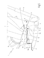
- Figure 1 shows a side view of a machine for mixing and pumping mortar, cement mixes, and similar, in accordance with the teachings of the present invention;
- Figure 2 shows a rear view in perspective, with parts removed for clarity, of the Figure 1 machine in a different operating position;
- Figures 3 and 4 show views in perspective, with parts removed for clarity, of a first variation of the rear of the Figure 1 machine in two different operating positions;
- Figure 5 shows a side view, with parts removed for clarity, of a second variation of the rear of the Figure 1 machine.
-
Number 1 in Figures 1 and 2 indicates as a whole a machine for mixing and pumping mortar, cement mixes, and similar, and which substantially comprises amortar tank 2 having atop inlet 2a through which it is possible to pour into the tank the various component materials of the mortar for pumping; a mixing member (not shown) fitted movably insidetank 2 to mix the mortar continuously; apump assembly 3 for pumping the mortar out oftank 2 at a predetermined pressure and/or flow rate; and adrive unit 4 for driving the mixing member andpump assembly 3. - In the example shown,
tank 2 comprises a cylindrical, substantiallyhorizontal vessel 5 having, on top, a cylindrical tubular stack orcollar 5a projecting vertically from the central body of the vessel to form theinlet 2a oftank 2, and amovable cover 6 for closing the top end oftubular collar 5a and so closinginlet 2a oftank 2 hermetically. - More specifically, in the example shown,
movable cover 6 is hinged directly to the side oftubular collar 5a to rotate freely, about a horizontal axis of rotation, to and from an operating position resting on the top end oftubular collar 5a to closeinlet 2a oftank 2 hermetically. - With reference to Figures 1 and 2,
machine 1 also comprises amovable loading bucket 7 hinged to the frame ofmachine 1, or rather totank 2 of the machine, to rotate about a horizontal dump axis A located preferably, though not necessarily, alongsidetubular collar 5a; and anactuating device 8 for movingmovable bucket 7, on command and about axis A, between a lowered position (shown by the dash line in Figure 1), in whichmovable bucket 7 is located alongsidetank 2, resting on the ground, and can be loaded with the material for forming the mortar, and a raised position (shown by the continuous line in Figure 1), in whichmovable bucket 7 is positioned upside down overtank 2, with theoutlet 7a of the movable bucket aligned withinlet 2a oftank 2, to discharge all the material inmovable bucket 7 by gravity intotank 2. - In the example shown, actuating
device 8 is defined by a hydraulic, single- or double-acting piston hinged at one end totank 2 and at the other end tomovable bucket 7. - In addition,
machine 1 preferably, though not necessarily, also comprises ahopper 9 hinged to the frame ofmachine 1, or rather totank 2 of the machine, close toinlet 2a, so as to rotate freely, about a horizontal axis of rotation, to and from an operating position, in whichhopper 9 is partly inserted insideinlet 2a oftank 2, i.e. insidetubular collar 5a, and is interposed betweenoutlet 7a ofmovable bucket 7 andinlet 2a oftank 2 whenmovable bucket 7 is in the raised position (Figure 1). - In the example shown,
hopper 9 is hinged totank 2, so that the horizontal axis of rotation of the hopper is coincident with dump axis A ofmovable bucket 7, and substantially comprises a substantially truncated-cone-, funnel-shaped body 10 with an outlet, i.e. smaller-diameter opening, sized to fit insidetubular collar 5a; and two parallel, facingarms 11 for connection to the frame, and which project from funnel-shaped body 10, and are hinged at the ends to the frame ofmachine 1 along dump axis A ofmovable bucket 7. -
Tank 2,pump assembly 3,drive unit 4,movable bucket 7,hydraulic piston 8, andhopper 9 are commonly used component parts in this particular field, and therefore require no further description. - With reference to Figure 2,
machine 1 also comprises aremovable guard grille 12 for closinginlet 2a oftank 2; and a vibratingmember 13 for vibratingguard grille 12, on command, to prevent material settling on the grille when being dumped intotank 2. - In the example shown,
guard grille 12 is defined by a flat, disk-shaped lattice structure which is sized to fit crosswise insidetubular collar 5a defining inlet 2a oftank 2, and is hinged to the wall oftubular collar 5a to rotate freely - about a horizontal axis of rotation B preferably, though not necessarily, parallel to the axis of rotation of movable cover 6 - between a first operating position, in whichflat lattice structure 12 is positioned horizontally, closingtubular collar 5a and, hence,inlet 2a, and a second operating position, in whichflat lattice structure 12 is positioned substantially vertically (Figure 2) to allow free access to the inside oftank 2 for routine maintenance. - More specifically, in the example shown,
guard grille 12 is hinged to the wall oftubular collar 5a defining inlet 2a oftank 2, with the interposition of anelastic joint 14 designed to prevent the vibration ofguard grille 12 being transmitted totank 2 and, hence, to the rest ofmachine 1. - With reference to Figure 2, vibrating
member 13, on the other hand, is fixed rigidly and directly to guardgrille 12, and is defined, in the example shown, by an electric, hydraulic, or pneumatic motor fixed appropriately to guardgrille 12, and by one or more rotating masses fitted to the output shaft of the motor so that the centre of gravity of the mass is eccentric with respect to the axis of rotation of the shaft, and so as to vibrate the entire structure when the mass is rotated by the motor; the whole being enclosed in a known protective outer casing. - Operation of
machine 1 for mixing and pumping mortar, cement mixes, and similar is easily deducible from the foregoing description and accompanying drawings, with no further explanation required. - The advantages of
machine 1 as described and illustrated herein are many and obvious: operation of vibratingmember 13 when fillingtank 2 prevents the material fromoutlet 7a ofmovable bucket 7 from accumulating onguard grille 12 and clogginginlet 2a oftank 2. - Clearly, changes may be made to machine 1 for mixing and pumping mortar, cement mixes, and similar as described and illustrated herein, without, however, departing from the scope of the present invention.
- In particular, with reference to Figures 3 and 4, as opposed to being fixed directly to
guard grille 12, vibratingmember 13 may be fixed rigidly to hopper 9, which, in this case, comprises retaining means for selectively makingguard grille 12 integral withhopper 9 when the hopper is inserted partly insidetubular collar 5a in the operating position. - In the example shown, the retaining means comprise a retaining plate 15 made of ferromagnetic material and fixed rigidly to guard
grille 12; and twoelectromagnets 16 fixed rigidly to hopper 9 to rest on retaining plate 15, whenhopper 9 is inserted partly insidetubular collar 5a, in the operating position, thus makingguard grille 12 integral withhopper 9. Obviously,electromagnets 16 may be replaced with permanent magnets or other mechanical retaining systems, such as two pins projecting fromhopper 9 and which engage seats, formed in retaining plate 15, whenhopper 9 is inserted partly insidetubular collar 5a, in the operating position. - In this variation,
hopper 9 is hinged to the frame ofmachine 1 with the interposition of elastic joints designed to prevent the vibration ofhopper 9 from being transmitted totank 2 and, hence, to the rest ofmachine 1. - In the example shown, each of the two
arms 11 connectinghopper 9 to the frame is divided into two portions, andhopper 9 has twoelastic joints 17, each for connecting the two portions of arelative arm 11 connecting the hopper to the frame. - In the Figure 5 variation, on the other hand,
guard grille 12 is fixed rigidly to, and closes, the outlet of funnel-shaped body 10, and vibratingmember 13 is fixed directly to the outside of funnel-shaped body 10, and vibrates, on command, the whole defined by funnel-shaped body 10 andguard grille 12, to prevent material from settling onguard grille 12 whenfilling tank 2. - In this variation, guard grille 12 obviously closes
inlet 2a oftank 2 whenhopper 9 is in the operating position. - As in the previous variation, each of the two
arms 11 ofhopper 9, projecting from funnel-shaped body 10 to connect the funnel-shaped body to the frame ofmachine 1 along axis A, is divided into two portions connected by a respectiveelastic joint 17. - In addition, in this variation,
machine 1 also comprises anauxiliary guard grille 18 fixed permanently to tank 2 to closeinlet 2a of the tank, andguard grille 12 is positioned parallel to and facingauxiliary guard grille 18 whenhopper 9 is in the operating position. - In the example shown,
auxiliary guard grille 18 is defined by a flat, disk-shaped lattice structure 18, which is sized to fit crosswise insidetubular collar 5a defining inlet 2a oftank 2, and is hinged to the wall oftubular collar 5a to rotate freely - about a horizontal axis of rotation C preferably, though not necessarily, parallel to the axis of rotation of movable cover 6 - between a first operating position, in whichflat lattice structure 18 is positioned horizontally (Figure 5), closingtubular collar 5a and, hence,inlet 2a, and a second operating position, in whichflat lattice structure 18 is positioned substantially vertically to allow free access to the inside oftank 2 for routine maintenance.
Claims (12)
- A machine (1) for mixing and pumping mortar, cement mixes, and similar, comprising a tank (2) having an inlet (2a) through which it is possible to pour into the tank the various component materials of the mortar for pumping; a movable loading bucket (7) hinged to the frame of the machine (1) to rotate about a substantially horizontal dump axis (A); and an actuating device (8) for moving said movable bucket (7), on command and about said dump axis (A), between a lowered position, in which the movable bucket (7) is located alongside the tank (2), and a raised position, in which the movable bucket (7) is positioned upside down over the tank (2), with the outlet (7a) of the movable bucket aligned with the inlet (2a) of said tank (2); said machine (1) for mixing and pumping mortar, cement mixes, and similar also comprising a guard grille (12) closing the inlet (2a) of the tank (2), and being characterized by also comprising vibrating means (13) for vibrating said guard grille (12) on command.
- A machine as claimed in Claim 1, characterized by comprising a hopper (9) hinged to the frame of the machine (1) to rotate, about a substantially horizontal axis of rotation (A), to and from an operating position, in which said hopper (9) is inserted partly inside the inlet (2a) of the tank (2), and is interposed between the outlet (7a) of said movable bucket (7) and the inlet (2a) of said tank (2) when the movable bucket (7) is in the raised position.
- A machine as claimed in Claim 1 or 2, characterized in that said guard grille (12) is fixed to said tank (2) at the inlet (2a) of the tank.
- A machine as claimed in Claim 3, characterized in that said vibrating means (13) comprise at least one vibrating member (13) fixed to said guard grille (12).
- A machine as claimed in Claim 3, characterized in that said vibrating means (13) comprise at least one vibrating member (13) fixed to said hopper (9) and retaining means for selectively making the hopper (9) rigidly integral with said guard grille (12) when the hopper (9) is in said operating position.
- A machine as claimed in Claim 5, characterized in that said hopper (9) is hinged to the frame of the machine (1) with the interposition of elastic means (17) designed to prevent vibration of the hopper (9) from being transmitted to the rest of the machine (1).
- A machine as claimed in any one of the foregoing Claims, characterized in that said guard grille (12) is fixed to the tank (2) with the interposition of elastic means (14) designed to prevent vibration of the guard grille (12) from being transmitted to the tank (2).
- A machine as claimed in Claim 2, characterized in that said hopper (9) comprises a funnel-shaped body (10) having an outlet sized for insertion inside the inlet (2a) of said tank (2); and in that said guard grille (12) is fixed to said funnel-shaped body (10) to close the outlet of the funnel-shaped body; the guard grille (12) being positioned closing the inlet (2a) of said tank (2) when the hopper (9) is in the operating position.
- A machine as claimed in Claim 8, characterized in that said vibrating means (13) comprise a vibrating member (13) fixed to said funnel-shaped body (10).
- A machine as claimed in Claim 8 or 9, characterized by also comprising an auxiliary guard grille (18) fixed to said tank (2) to close the inlet (2a) of the tank; said guard grille (12) being positioned parallel to and facing said auxiliary guard grille (18) when the hopper (9) is in the operating position.
- A machine as claimed in any one of the foregoing Claims, characterized by also comprising a pump assembly (3) for pumping mortar out of said tank (2) at a predetermined pressure and/or flow rate; and a drive unit (4) for driving said pump assembly (3).
- A machine as claimed in any one of the foregoing Claims, characterized in that said tank (2) comprises a vessel (5) having, on top, a tubular stack or collar (5a) projecting vertically to form the inlet (2a) of the tank (2), and a movable cover (6) which can be positioned closing the top end of said tubular collar (5a) to hermetically close the inlet (2a) of said tank (2).
Applications Claiming Priority (2)
| Application Number | Priority Date | Filing Date | Title |
|---|---|---|---|
| ITTO20040864 ITTO20040864A1 (en) | 2004-12-10 | 2004-12-10 | MACHINE FOR PUMPING AND DISTRIBUTION OF MORTARS, CAMENTIZED AND SIMILAR PASTRIES |
| ITTO20050645 ITTO20050645A1 (en) | 2005-09-20 | 2005-09-20 | MACHINE FOR MIXING AND PUMPING OF MORTARS, PLASTERS AND CEMENT MIXTURES IN GENERAL |
Publications (2)
| Publication Number | Publication Date |
|---|---|
| EP1669180A2 true EP1669180A2 (en) | 2006-06-14 |
| EP1669180A3 EP1669180A3 (en) | 2006-12-13 |
Family
ID=36047995
Family Applications (1)
| Application Number | Title | Priority Date | Filing Date |
|---|---|---|---|
| EP05111932A Withdrawn EP1669180A3 (en) | 2004-12-10 | 2005-12-09 | Machine for mixing and pumping mortar, plaster and cement mixes in general |
Country Status (1)
| Country | Link |
|---|---|
| EP (1) | EP1669180A3 (en) |
Cited By (10)
| Publication number | Priority date | Publication date | Assignee | Title |
|---|---|---|---|---|
| WO2008129100A1 (en) * | 2007-04-23 | 2008-10-30 | Utiform Technologies, Sl | Cooling system for machines used to transport construction materials |
| WO2011008716A3 (en) * | 2009-07-11 | 2011-03-10 | Stephen Degaray | System and process for delivering building materials |
| EP2838701A4 (en) * | 2012-04-18 | 2016-01-06 | Ali Nemdil | Concrete pump |
| FR3032627A1 (en) * | 2015-02-17 | 2016-08-19 | 2C Distrib | DEVICE FOR MIXING PULVERULENT PRODUCT |
| US9738461B2 (en) | 2007-03-20 | 2017-08-22 | Pump Truck Industrial LLC | System and process for delivering building materials |
| EP3213812A1 (en) * | 2016-03-01 | 2017-09-06 | Staring Maskinfabrik A/S | Mixing machine |
| ITUA20162273A1 (en) * | 2016-04-04 | 2017-10-04 | Turbosol Produzione Spa | MACHINE FOR PUMPING OF BUILDING MATERIALS |
| CN109227940A (en) * | 2018-11-20 | 2019-01-18 | 四川德程建设有限公司 | A kind of Multi-function concrete mixer |
| US11203879B2 (en) | 2006-03-23 | 2021-12-21 | Pump Truck Industrial, LLC | System and process for delivering building materials |
| FR3116226A1 (en) * | 2020-11-18 | 2022-05-20 | Pl2M | Construction machine with remote vibration source |
Family Cites Families (3)
| Publication number | Priority date | Publication date | Assignee | Title |
|---|---|---|---|---|
| FR2690146B1 (en) * | 1992-04-15 | 1994-07-22 | Vidal Lucien | PROCESS FOR THE PNEUMATIC TRANSPORT OF BULK MATERIALS, SUCH AS SCREED MORTAR, CONCRETE, SAND, AND A MIXER CONVEYOR USING THIS PROCESS. |
| DE4402275C2 (en) * | 1994-01-27 | 1997-12-18 | Putzmeister Ag | Filling device for bulk goods |
| DE19534013A1 (en) * | 1995-09-14 | 1997-03-20 | Putzmeister Maschf | Loading device for bulk goods |
-
2005
- 2005-12-09 EP EP05111932A patent/EP1669180A3/en not_active Withdrawn
Cited By (17)
| Publication number | Priority date | Publication date | Assignee | Title |
|---|---|---|---|---|
| US9951535B2 (en) | 2006-03-23 | 2018-04-24 | Pump Truck Industrial LLC | System and process for mixing and delivering building materials |
| US11203879B2 (en) | 2006-03-23 | 2021-12-21 | Pump Truck Industrial, LLC | System and process for delivering building materials |
| US11198567B2 (en) | 2006-03-23 | 2021-12-14 | Pump Truck Industrial LLC | System and process for delivering building materials |
| US9738461B2 (en) | 2007-03-20 | 2017-08-22 | Pump Truck Industrial LLC | System and process for delivering building materials |
| ES2306614A1 (en) * | 2007-04-23 | 2008-11-01 | Utiform Technologies, S.L. | Cooling system for machines used to transport construction materials |
| ES2306614B1 (en) * | 2007-04-23 | 2009-11-06 | Utiform Technologies, S.L. | REFRIGERATION SYSTEM FOR CONSTRUCTION MACHINES FOR CONSTRUCTION. |
| WO2008129100A1 (en) * | 2007-04-23 | 2008-10-30 | Utiform Technologies, Sl | Cooling system for machines used to transport construction materials |
| WO2011008716A3 (en) * | 2009-07-11 | 2011-03-10 | Stephen Degaray | System and process for delivering building materials |
| EP2838701A4 (en) * | 2012-04-18 | 2016-01-06 | Ali Nemdil | Concrete pump |
| FR3032627A1 (en) * | 2015-02-17 | 2016-08-19 | 2C Distrib | DEVICE FOR MIXING PULVERULENT PRODUCT |
| DK201600132A1 (en) * | 2016-03-01 | 2017-10-02 | Staring Maskf As | Mixer |
| DK179342B1 (en) * | 2016-03-01 | 2018-05-14 | Staring Maskf A/S | Mixer |
| EP3213812A1 (en) * | 2016-03-01 | 2017-09-06 | Staring Maskinfabrik A/S | Mixing machine |
| ITUA20162273A1 (en) * | 2016-04-04 | 2017-10-04 | Turbosol Produzione Spa | MACHINE FOR PUMPING OF BUILDING MATERIALS |
| CN109227940A (en) * | 2018-11-20 | 2019-01-18 | 四川德程建设有限公司 | A kind of Multi-function concrete mixer |
| FR3116226A1 (en) * | 2020-11-18 | 2022-05-20 | Pl2M | Construction machine with remote vibration source |
| EP4000837A1 (en) * | 2020-11-18 | 2022-05-25 | Pl2M | Machine for construction site with offset vibration source |
Also Published As
| Publication number | Publication date |
|---|---|
| EP1669180A3 (en) | 2006-12-13 |
Similar Documents
| Publication | Publication Date | Title |
|---|---|---|
| KR102470711B1 (en) | Device for dosing a powder, in particular a pulverulent pharmaceutical | |
| JP2023009167A (en) | Apparatus for mixing | |
| ES2954598T3 (en) | Procedure for supplying solid material to a mixing device, solid material supply device and mixing device | |
| CN114765403A (en) | Freezing burr removing device | |
| JPH0543597B2 (en) | ||
| EP1669180A3 (en) | Machine for mixing and pumping mortar, plaster and cement mixes in general | |
| KR101779396B1 (en) | Apparatus for safely transferring radioactive waste | |
| KR102480365B1 (en) | High-strength mortar mixing equipment | |
| EP0880631B1 (en) | Material outfeeding device for vehicles | |
| CN216756326U (en) | Raw material feeding equipment for preparing pesticide bactericide | |
| CN108189241A (en) | Truck mixer | |
| JPS6214715B2 (en) | ||
| CN102627192A (en) | Medicine chest of medicine arrangement machine | |
| JP2002225031A (en) | Powder and granular material supply apparatus and powder and granular material supply method | |
| KR102450672B1 (en) | Bottleneck removing module for portable silo apparatus, portable silo apparatus comprising the bottleneck removing module for portable silo apparatus | |
| KR102450673B1 (en) | Twin rotary-type supply module for portable silo apparatus, portable silo apparatus comprising the twin rotary-type supply module for portable silo apparatus | |
| JP2001057859A (en) | Coagulant feeder | |
| CN222567540U (en) | Vacuum stirring device | |
| JP2002001076A (en) | Solution preparation equipment | |
| CN111358026B (en) | Feed proportioning device and batching equipment thereof | |
| CN115492391B (en) | Concrete pumping and delivery device and method thereof | |
| EP1336427A1 (en) | Method and apparatus for preparing slurry from starting materials | |
| KR940002586B1 (en) | Vertical vibrator of brick making apparatus | |
| EP0398401B1 (en) | Installation for preparing and transporting mortar on a building site | |
| JP2019166754A (en) | Powder transfer device, powder treatment device, and suction nozzle |
Legal Events
| Date | Code | Title | Description |
|---|---|---|---|
| PUAI | Public reference made under article 153(3) epc to a published international application that has entered the european phase |
Free format text: ORIGINAL CODE: 0009012 |
|
| AK | Designated contracting states |
Kind code of ref document: A2 Designated state(s): AT BE BG CH CY CZ DE DK EE ES FI FR GB GR HU IE IS IT LI LT LU LV MC NL PL PT RO SE SI SK TR |
|
| AX | Request for extension of the european patent |
Extension state: AL BA HR MK YU |
|
| PUAL | Search report despatched |
Free format text: ORIGINAL CODE: 0009013 |
|
| AK | Designated contracting states |
Kind code of ref document: A3 Designated state(s): AT BE BG CH CY CZ DE DK EE ES FI FR GB GR HU IE IS IT LI LT LU LV MC NL PL PT RO SE SI SK TR |
|
| AX | Request for extension of the european patent |
Extension state: AL BA HR MK YU |
|
| RIC1 | Information provided on ipc code assigned before grant |
Ipc: B65D 88/66 20060101ALN20061109BHEP Ipc: B28C 7/08 20060101ALI20061109BHEP Ipc: E04G 21/04 20060101ALI20061109BHEP Ipc: B28C 7/16 20060101ALI20061109BHEP Ipc: B28C 7/06 20060101ALI20061109BHEP Ipc: B28C 5/12 20060101AFI20061109BHEP |
|
| RAP1 | Party data changed (applicant data changed or rights of an application transferred) |
Owner name: SVILUPPO 68 S.R.L. |
|
| RAP1 | Party data changed (applicant data changed or rights of an application transferred) |
Owner name: TURBOSOL PRODUZIONE S.P.A. |
|
| 17P | Request for examination filed |
Effective date: 20070608 |
|
| 17Q | First examination report despatched |
Effective date: 20070716 |
|
| AKX | Designation fees paid |
Designated state(s): DE FR IT |
|
| RAP1 | Party data changed (applicant data changed or rights of an application transferred) |
Owner name: TURBOSOL PRODUZIONE S.P.A. |
|
| STAA | Information on the status of an ep patent application or granted ep patent |
Free format text: STATUS: THE APPLICATION IS DEEMED TO BE WITHDRAWN |
|
| 18D | Application deemed to be withdrawn |
Effective date: 20090701 |