EP1670112A1 - Flush mounted electrical box - Google Patents
Flush mounted electrical box Download PDFInfo
- Publication number
- EP1670112A1 EP1670112A1 EP05077839A EP05077839A EP1670112A1 EP 1670112 A1 EP1670112 A1 EP 1670112A1 EP 05077839 A EP05077839 A EP 05077839A EP 05077839 A EP05077839 A EP 05077839A EP 1670112 A1 EP1670112 A1 EP 1670112A1
- Authority
- EP
- European Patent Office
- Prior art keywords
- box
- edge
- circumferential wall
- wall
- box according
- Prior art date
- Legal status (The legal status is an assumption and is not a legal conclusion. Google has not performed a legal analysis and makes no representation as to the accuracy of the status listed.)
- Granted
Links
Images


Classifications
-
- H—ELECTRICITY
- H02—GENERATION; CONVERSION OR DISTRIBUTION OF ELECTRIC POWER
- H02G—INSTALLATION OF ELECTRIC CABLES OR LINES, OR OF COMBINED OPTICAL AND ELECTRIC CABLES OR LINES
- H02G3/00—Installations of electric cables or lines or protective tubing therefor in or on buildings, equivalent structures or vehicles
- H02G3/02—Details
- H02G3/08—Distribution boxes; Connection or junction boxes
- H02G3/12—Distribution boxes; Connection or junction boxes for flush mounting
- H02G3/121—Distribution boxes; Connection or junction boxes for flush mounting in plain walls
Definitions
- the invention relates to a box for electric wirings.
- Such a box may for instance be a so-called flush-type box, which is placed in a hole made in a wall and connecting to a slot for the conduit pipe slotted or sawn into the wall in question.
- a flush-type box which is placed in a hole made in a wall and connecting to a slot for the conduit pipe slotted or sawn into the wall in question.
- conduit pipes are placed into the wall before it is usually finished with a coat of plaster.
- the type of box used among others depends on the type of switching material the box should contain and the thickness of the wall in question (thick bearing wall, or thin partition wall). These conditions determine what depth the box to be used should have.
- boxes having various depths suitable for the locations in question need to be on hand in the right quantities. If it turns out that a box cannot after all be used at a certain location in a certain wall or that a box of another depth is indeed necessary at that location, a box having another depth will have to be used. These things will have to be anticipated, in which case more boxes than strictly necessary need to be brought along. Alternatively another box will have to be picked up from a place of storage, which will mean an interruption of a smooth, systematic continuation of the activities.
- Another drawback is that it is necessary to determine beforehand what box depths are necessary, and to order those boxes from the wholesalers/manufacturer. Those companies have to stock them or make production facilities available for them, respectively.
- Another problem may occur when the hole for the box is not deep enough. In that case as well the box on hand will have to be changed for another less deep box.
- the invention provides a box for electric wirings, comprising a circumferential wall and a bottom wall connecting to a first edge of the circumferential wall, which form a chamber for a contact- or switch unit for the electric wiring, wherein the circumferential wall defines an opening at a second edge opposite to the first edge, which opening is intended to be facing a living quarter after having been installed, wherein the box is furthermore provided with a passage for passing electric wires through to the chamber, wherein the bottom comprises at least one bottom portion that is movable between a first position and at least one second position in which the bottom portion is situated at a different distance from the second edge than in the first position.
- the box according to the invention has an initial depth and can easily be given another depth, in order to be thus adapted to the actual wall thickness, hole deepness and/or interior work to be incorporated.
- the box thus has several (potential) depths.
- the electrical fitter may judge in situ what box depth is necessary, and subsequently take measures by changing the depth of the box.
- the user does not need to make a choice as regards box depths yet.
- a stock of boxes of different depths need not be held either.
- circumferential wall and the bottom wall have been formed as one unity with each other and they comprise a deformable portion, which deformable portion can be changed between a first in itself stable condition for the first position of the bottom portion and at least one in itself stable second condition for the at least one second position of the bottom portion.
- the bottom portion is connected to the remaining part of the box by means of a hinge connection, so that the electrical fitter can easily change the total height, if necessary.
- the hinge connection is formed in the material of the bottom, preferably by folding lines in the material of the box.
- An enlargement of the content of the box can be enhanced if the bottom portion is situated concentric to the circumferential wall.
- the bottom portion in a direction transverse to the circumferential wall is preferably situated at a short distance from the first edge, so that the enlargement can be as large as possible, considering the profile of the interior to be placed.
- the first and the second edge can be spaced apart at a fixed distance from each other.
- the bottom portion may be movable between a first position and at least one second position in which the bottom portion is situated at a different distance from the first edge than in the first position.
- the invention provides a box for electric wirings, comprising a circumferential wall and a bottom wall formed as one unity with the circumferential wall and connecting to a first edge of the circumferential wall, which form a chamber for a contact- or switch unit for the electric wiring, wherein the circumferential wall defines an opening at a second edge opposite to the first edge, which opening is intended to be facing a living quarter after having been installed, wherein the box is furthermore provided with a passage for passing electric wires through to the chamber, wherein the bottom is at least partially extendable and/or retractable in a direction perpendicular to the bottom between in themselves stable conditions.
- the invention provides a box for electric wirings, comprising a wall having a circumferential wall and a bottom wall connecting to a first edge of the circumferential wall, wherein the depth of the box defined by the bottom wall is adjustable between at least two different depths.
- the depth of the box can be adjustable by a turning motion of a portion of the wall of the box.
- the box may have a turnable portion in the transition between circumferential wall and bottom wall.
- the said movable bottom portion may in one embodiment extend over nearly the entire bottom.
- the box is designed like a flush-type box.
- German patent application 28 02 893 a box for electric wirings is known, of which the circumferential wall is provided with a bellows-shaped portion, by means of which the position of the bottom and the circumferential wall portion between bottom a bellows-shaped portion can be adjusted to the depth of a hole in a wall, under the influence of support forces of the hole bottom.
- the box 1 shown in the figures 1-5 is designed like a flush-type box, for instance made of polypropylene, and has a circle-cylindrical circumferential wall 2 having centre line S and a bottom wall 3 that has been formed as one unity with the circumferential wall 2. At the side facing away from the bottom 3 a circular opening 4 is left open, through which the interior for the flush-type box 1 can be inserted into the inside 5 of the box 1.
- a spout 12 extends outward from the circumferential wall 2, for connection to a wiring pipe.
- the bottom 3 has a small circumferential edge area 10 at the location of the connection to the circumferential wall 2, which area in radial inward direction via a circular folding line 6 changes into a circular circumferential strip 7, which at its radial inward edge via circular folding line 8 changes into a circular circumferential strip 9.
- the circumferential strip 9 surrounds a bottom plate 11 that is solidly connected thereto and is substantially perpendicular to said bottom plate.
- the folding lines 6 and 8 are concentric to the centre line S.
- the folding lines 6 and 8 are formed by weakenings in the material at that location, such as for instance a living hinge.
- the folding lines 6 and 8 are situated as close to the edge 10 as possible, in order to let the extendable portion of the bottom 3 be as large as possible.
- the bottom portion with circumferential strip 9 and bottom plate 11 is situated relatively inward, wherein the surface of the bottom plate 11 only slightly projects from the circumferential edge 10 of the bottom 3.
- the box 1 has a depth H 1.
- the circumferential strip 7 in that case extends from the circumferential edge 10 inward into the inside 5 of the box 1.
- the box 1 with the depth H1 is suitable to be placed in the hole 23 in the wall 20 shown in figure 3.
- the box 1 can in that case be placed with its bottom plate 11 against the bottom surface 24 of the hole 23, and as H1 is slightly smaller than the depth D1 of the hole 23 the edge of the opening 4 remains within the surface 21 of the wall 20.
- a slot 26 is present for a wiring pipe, which can be connected to the spout 12.
- the depth of the hole 23 would be larger, for instance D2, as indicated in dashed lines in figure 3, said hole would be suitable for accommodation of a box having a larger content, for instance for accommodating other switch material.
- the content of the box according to the invention can easily be enlarged, by pressing on the bottom plate 11 from the inside so that the circumferential strip 7 is folded to the outside about folding line 6, wherein circumferential strip 7 tilts about folding line 8 with respect to circumferential strip 9, while passing through a plane parallel to the bottom, and the bottom 3 will take up the stable position shown in figure 5.
- both the circumferential strip 7 and the circumferential strip 9 will extend downward from the edge 10, in order to enlarge the box depth from H1 to H2. With that depth the flush-type box 1 fits more properly in the hole 23 which has a depth D2.
Landscapes
- Engineering & Computer Science (AREA)
- Architecture (AREA)
- Civil Engineering (AREA)
- Structural Engineering (AREA)
- Connection Or Junction Boxes (AREA)
- Coin-Freed Apparatuses For Hiring Articles (AREA)
- Switch Cases, Indication, And Locking (AREA)
- Road Signs Or Road Markings (AREA)
- Washing And Drying Of Tableware (AREA)
- Vending Machines For Individual Products (AREA)
- Portable Nailing Machines And Staplers (AREA)
- Massaging Devices (AREA)
- Dry Shavers And Clippers (AREA)
Abstract
Description
- The invention relates to a box for electric wirings.
- Such a box may for instance be a so-called flush-type box, which is placed in a hole made in a wall and connecting to a slot for the conduit pipe slotted or sawn into the wall in question. In newly built houses such boxes and conduit pipes are placed into the wall before it is usually finished with a coat of plaster.
- The type of box used among others depends on the type of switching material the box should contain and the thickness of the wall in question (thick bearing wall, or thin partition wall). These conditions determine what depth the box to be used should have. When wiring, boxes having various depths suitable for the locations in question need to be on hand in the right quantities. If it turns out that a box cannot after all be used at a certain location in a certain wall or that a box of another depth is indeed necessary at that location, a box having another depth will have to be used. These things will have to be anticipated, in which case more boxes than strictly necessary need to be brought along. Alternatively another box will have to be picked up from a place of storage, which will mean an interruption of a smooth, systematic continuation of the activities.
- Another drawback is that it is necessary to determine beforehand what box depths are necessary, and to order those boxes from the wholesalers/manufacturer. Those companies have to stock them or make production facilities available for them, respectively.
- Another problem may occur when the hole for the box is not deep enough. In that case as well the box on hand will have to be changed for another less deep box.
- It is an object of the invention to improve on this.
- From one aspect the invention provides a box for electric wirings, comprising a circumferential wall and a bottom wall connecting to a first edge of the circumferential wall, which form a chamber for a contact- or switch unit for the electric wiring, wherein the circumferential wall defines an opening at a second edge opposite to the first edge, which opening is intended to be facing a living quarter after having been installed, wherein the box is furthermore provided with a passage for passing electric wires through to the chamber, wherein the bottom comprises at least one bottom portion that is movable between a first position and at least one second position in which the bottom portion is situated at a different distance from the second edge than in the first position.
- The box according to the invention has an initial depth and can easily be given another depth, in order to be thus adapted to the actual wall thickness, hole deepness and/or interior work to be incorporated. The box thus has several (potential) depths. The electrical fitter may judge in situ what box depth is necessary, and subsequently take measures by changing the depth of the box. When ordering the boxes the user does not need to make a choice as regards box depths yet. A stock of boxes of different depths need not be held either. In a simple embodiment the circumferential wall and the bottom wall have been formed as one unity with each other and they comprise a deformable portion, which deformable portion can be changed between a first in itself stable condition for the first position of the bottom portion and at least one in itself stable second condition for the at least one second position of the bottom portion.
- Preferably the bottom portion is connected to the remaining part of the box by means of a hinge connection, so that the electrical fitter can easily change the total height, if necessary.
- In an easy to manufacture embodiment the hinge connection is formed in the material of the bottom, preferably by folding lines in the material of the box.
- Moving the bottom portion is facilitated when the hinge connection is formed by a strip of material of the box that is situated between folding lines.
- An enlargement of the content of the box can be enhanced if the bottom portion is situated concentric to the circumferential wall. In that case the bottom portion in a direction transverse to the circumferential wall is preferably situated at a short distance from the first edge, so that the enlargement can be as large as possible, considering the profile of the interior to be placed.
- The first and the second edge can be spaced apart at a fixed distance from each other.
- The bottom portion may be movable between a first position and at least one second position in which the bottom portion is situated at a different distance from the first edge than in the first position.
- From another aspect the invention provides a box for electric wirings, comprising a circumferential wall and a bottom wall formed as one unity with the circumferential wall and connecting to a first edge of the circumferential wall, which form a chamber for a contact- or switch unit for the electric wiring, wherein the circumferential wall defines an opening at a second edge opposite to the first edge, which opening is intended to be facing a living quarter after having been installed, wherein the box is furthermore provided with a passage for passing electric wires through to the chamber, wherein the bottom is at least partially extendable and/or retractable in a direction perpendicular to the bottom between in themselves stable conditions.
- From another aspect the invention provides a box for electric wirings, comprising a wall having a circumferential wall and a bottom wall connecting to a first edge of the circumferential wall, wherein the depth of the box defined by the bottom wall is adjustable between at least two different depths.
- The depth of the box can be adjustable by a turning motion of a portion of the wall of the box. For that purpose the box may have a turnable portion in the transition between circumferential wall and bottom wall.
- The said movable bottom portion may in one embodiment extend over nearly the entire bottom.
- In one embodiment the box is designed like a flush-type box.
- It is noted that from German patent application 28 02 893 a box for electric wirings is known, of which the circumferential wall is provided with a bellows-shaped portion, by means of which the position of the bottom and the circumferential wall portion between bottom a bellows-shaped portion can be adjusted to the depth of a hole in a wall, under the influence of support forces of the hole bottom.
- It is furthermore noted that from European patent application 1.003.260 a two-part box is known, wherein a circumferential wall is provided with a bellows-shaped portion and a mounting sleeve to be inserted into the bellows-shaped portion is provided with external teeth for securing a position of the bellows-shaped portion and thus the depth of the assembly of the box including mounting sleeve.
- The invention will be elucidated on the basis of a number of exemplary embodiments shown in the attached drawings, in which:
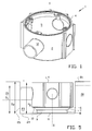
- Figure 1 shows an isometric view diagonally from above of an exemplary embodiment of a box according to the invention;
- Figure 2 shows an isometric view diagonally from underneath of the box of figure 1;
- Figure 2A shows a bottom view of the box of figure 1;
- Figure 3 shows the box of figure 1, in a condition in which it is placed in a wall;
- Figure 4 shows an isometric view diagonally from underneath of the box of figures 1 and 2, with extended bottom; and
- Figure 5 shows the box of figure 4, in a condition in which it is placed in a wall.
- The
box 1 shown in the figures 1-5 is designed like a flush-type box, for instance made of polypropylene, and has a circle-cylindricalcircumferential wall 2 having centre line S and abottom wall 3 that has been formed as one unity with thecircumferential wall 2. At the side facing away from the bottom 3 acircular opening 4 is left open, through which the interior for the flush-type box 1 can be inserted into theinside 5 of thebox 1. - A
spout 12 extends outward from thecircumferential wall 2, for connection to a wiring pipe. - The
bottom 3 has a smallcircumferential edge area 10 at the location of the connection to thecircumferential wall 2, which area in radial inward direction via acircular folding line 6 changes into a circularcircumferential strip 7, which at its radial inward edge viacircular folding line 8 changes into a circularcircumferential strip 9. Thecircumferential strip 9 surrounds abottom plate 11 that is solidly connected thereto and is substantially perpendicular to said bottom plate. - The
folding lines folding lines folding lines edge 10 as possible, in order to let the extendable portion of thebottom 3 be as large as possible. - In the stable condition shown in figure 2, the bottom portion with
circumferential strip 9 andbottom plate 11 is situated relatively inward, wherein the surface of thebottom plate 11 only slightly projects from thecircumferential edge 10 of thebottom 3. In that condition, shown in figure 3, thebox 1 has adepth H 1. Thecircumferential strip 7 in that case extends from thecircumferential edge 10 inward into theinside 5 of thebox 1. - In this example the
box 1 with the depth H1 is suitable to be placed in thehole 23 in the wall 20 shown in figure 3. Thebox 1 can in that case be placed with itsbottom plate 11 against thebottom surface 24 of thehole 23, and as H1 is slightly smaller than the depth D1 of thehole 23 the edge of theopening 4 remains within thesurface 21 of the wall 20. - It is furthermore shown that in the wall 20, starting from the
wall portion 25 of thehole 23, aslot 26 is present for a wiring pipe, which can be connected to thespout 12. - If the depth of the
hole 23 would be larger, for instance D2, as indicated in dashed lines in figure 3, said hole would be suitable for accommodation of a box having a larger content, for instance for accommodating other switch material. The content of the box according to the invention can easily be enlarged, by pressing on thebottom plate 11 from the inside so that thecircumferential strip 7 is folded to the outside aboutfolding line 6, whereincircumferential strip 7 tilts aboutfolding line 8 with respect tocircumferential strip 9, while passing through a plane parallel to the bottom, and thebottom 3 will take up the stable position shown in figure 5. In that case both thecircumferential strip 7 and thecircumferential strip 9 will extend downward from theedge 10, in order to enlarge the box depth from H1 to H2. With that depth the flush-type box 1 fits more properly in thehole 23 which has a depth D2. - On the other hand, in case of a flush-
type box 1 having an enlarged depth H2, shown in figure 5, which has to be placed in ahole 23 having a depth D1, shown in dashed lines in figure 5, the depth can easily be reduced to H1, by pressing on thebottom plate 11, so that thebottom 3 by folding in changes from the position shown in figure 4 to the condition shown in figure 2.
Claims (16)
- Box for electric wirings, comprising a circumferential wall and a bottom wall connecting to a first edge of the circumferential wall, which form a chamber for a contact- or switch unit for the electric wiring, wherein the circumferential wall defines an opening at a second edge opposite to the first edge, which opening is intended to be facing a living quarter after having been installed, wherein the box is furthermore provided with a passage for passing electric wires through to the chamber, wherein the bottom comprises at least one bottom portion that is movable between a first position and at least one second position in which the bottom portion is situated at a different distance from the second edge than in the first position.
- Box according to claim 1, wherein the circumferential wall and the bottom wall have been formed as one unity with each other and comprise a deformable portion, which deformable portion can be changed between a first in itself stable condition for the first position of the bottom portion and at least one in itself stable second condition for the at least one second position of the bottom portion.
- Box according to claim 1 or 2, wherein the bottom portion is connected to the remaining part of the box by means of a hinge connection.
- Box according to claim 3, wherein the hinge connection is formed in the material of the bottom.
- Box according to claim 3 or 4, wherein the hinge connection is formed by folding lines in the material of the box.
- Box according to claim 5, wherein the hinge connection is formed by a strip of material of the box that is situated between folding lines.
- Box according to any one of the preceding claims, wherein the bottom portion is situated concentric to the circumferential wall, wherein preferably the bottom portion in a direction transverse to the circumferential wall is situated at a short distance from the first edge.
- Box according to any one of the preceding claims, wherein the first and the second edge are spaced apart at a fixed distance from each other.
- Box according to any one of the preceding claims, wherein the bottom portion is movable between a first position and at least one second position in which the bottom portion is situated at a different distance from the first edge than in the first position.
- Box according to any one of the preceding claims, wherein the said movable bottom portion extends over nearly the entire bottom.
- Box for electric wirings, comprising a circumferential wall and a bottom wall connecting to a first edge of the circumferential wall and formed as one unity with the circumferential wall, which form a chamber for a contact- or switch unit for the electric wiring, wherein the circumferential wall defines an opening at a second edge opposite to the first edge, which opening is intended to be facing a living quarter after having been installed, wherein the box is furthermore provided with a passage for passing electric wires through to the chamber, wherein the bottom is at least partially extendable and/or retractable in a direction perpendicular to the bottom between in themselves stable conditions.
- Box according to claim 11, wherein the bottom is at least partially extendable and/or retractable with respect to the first edge.
- Box for electric wirings, comprising a wall having a circumferential wall and a bottom wall connecting to a first edge of the circumferential wall, wherein the depth of the box defined by the bottom wall is adjustable between at least two different in themselves stable depths.
- Box according to claim 13, wherein the depth of the box is adjustable by a turning motion of a portion of the wall of the box.
- Box according to claim 14, wherein the box has a turnable portion in the transition between circumferential wall and bottom wall.
- Box according to any one of the preceding claims, designed like a flush-type box.
Applications Claiming Priority (1)
| Application Number | Priority Date | Filing Date | Title |
|---|---|---|---|
| NL1027704A NL1027704C2 (en) | 2004-12-10 | 2004-12-10 | Box for electrical installations. |
Publications (2)
| Publication Number | Publication Date |
|---|---|
| EP1670112A1 true EP1670112A1 (en) | 2006-06-14 |
| EP1670112B1 EP1670112B1 (en) | 2008-03-12 |
Family
ID=34974546
Family Applications (1)
| Application Number | Title | Priority Date | Filing Date |
|---|---|---|---|
| EP05077839A Expired - Lifetime EP1670112B1 (en) | 2004-12-10 | 2005-12-09 | Flush mounted electrical box |
Country Status (7)
| Country | Link |
|---|---|
| EP (1) | EP1670112B1 (en) |
| AT (1) | ATE389256T1 (en) |
| DE (1) | DE602005005274T2 (en) |
| DK (1) | DK1670112T3 (en) |
| ES (1) | ES2302121T3 (en) |
| NL (1) | NL1027704C2 (en) |
| PT (1) | PT1670112E (en) |
Cited By (3)
| Publication number | Priority date | Publication date | Assignee | Title |
|---|---|---|---|---|
| DE202015101801U1 (en) | 2015-04-13 | 2015-05-04 | Kaiser Gmbh & Co. Kg | Installation box for electrical appliances |
| EP3506443A1 (en) * | 2017-12-29 | 2019-07-03 | Legrand France | Variable depth electrical box |
| EP3958416A1 (en) | 2020-08-17 | 2022-02-23 | Attema B.V. | Installation box with variable height |
Citations (3)
| Publication number | Priority date | Publication date | Assignee | Title |
|---|---|---|---|---|
| DE2802893A1 (en) * | 1978-01-24 | 1979-07-26 | Bbc Brown Boveri & Cie | Wall-inset housing for electrical installation - has elastic region in centre of side walls to accommodate different recess depths |
| US5142102A (en) * | 1990-12-06 | 1992-08-25 | Pacific Rim Polytech Corp. | Multiple tier junction box |
| EP1003260A1 (en) * | 1998-11-19 | 2000-05-24 | Legrand | Flush mounted box with fan foldings, in particular for electrical apparatus and its manufacturing process |
-
2004
- 2004-12-10 NL NL1027704A patent/NL1027704C2/en not_active IP Right Cessation
-
2005
- 2005-12-09 DK DK05077839T patent/DK1670112T3/en active
- 2005-12-09 PT PT05077839T patent/PT1670112E/en unknown
- 2005-12-09 EP EP05077839A patent/EP1670112B1/en not_active Expired - Lifetime
- 2005-12-09 DE DE602005005274T patent/DE602005005274T2/en not_active Expired - Lifetime
- 2005-12-09 ES ES05077839T patent/ES2302121T3/en not_active Expired - Lifetime
- 2005-12-09 AT AT05077839T patent/ATE389256T1/en active
Patent Citations (3)
| Publication number | Priority date | Publication date | Assignee | Title |
|---|---|---|---|---|
| DE2802893A1 (en) * | 1978-01-24 | 1979-07-26 | Bbc Brown Boveri & Cie | Wall-inset housing for electrical installation - has elastic region in centre of side walls to accommodate different recess depths |
| US5142102A (en) * | 1990-12-06 | 1992-08-25 | Pacific Rim Polytech Corp. | Multiple tier junction box |
| EP1003260A1 (en) * | 1998-11-19 | 2000-05-24 | Legrand | Flush mounted box with fan foldings, in particular for electrical apparatus and its manufacturing process |
Cited By (6)
| Publication number | Priority date | Publication date | Assignee | Title |
|---|---|---|---|---|
| DE202015101801U1 (en) | 2015-04-13 | 2015-05-04 | Kaiser Gmbh & Co. Kg | Installation box for electrical appliances |
| EP3091624A1 (en) | 2015-04-13 | 2016-11-09 | Kaiser GmbH & Co. KG | Installation socket for electric appliances |
| EP3506443A1 (en) * | 2017-12-29 | 2019-07-03 | Legrand France | Variable depth electrical box |
| FR3076405A1 (en) * | 2017-12-29 | 2019-07-05 | Legrand France | ELECTRICAL BOX WITH VARIABLE DEPTH |
| EP3958416A1 (en) | 2020-08-17 | 2022-02-23 | Attema B.V. | Installation box with variable height |
| NL2026275B1 (en) | 2020-08-17 | 2022-04-14 | Attema B V | Installation box with variable height |
Also Published As
| Publication number | Publication date |
|---|---|
| EP1670112B1 (en) | 2008-03-12 |
| NL1027704C2 (en) | 2006-06-19 |
| ATE389256T1 (en) | 2008-03-15 |
| DK1670112T3 (en) | 2008-07-07 |
| DE602005005274D1 (en) | 2008-04-24 |
| ES2302121T3 (en) | 2008-07-01 |
| DE602005005274T2 (en) | 2009-03-26 |
| PT1670112E (en) | 2008-04-28 |
Similar Documents
| Publication | Publication Date | Title |
|---|---|---|
| CA2638202C (en) | Electrical outlet box having high and low voltage compartments | |
| US6232553B1 (en) | Junction box improvements | |
| WO2002058202A1 (en) | Floor box assembly | |
| US20040149475A1 (en) | Cable entry box | |
| US20100267278A1 (en) | Outlet assemblies & methods of installation thereof | |
| EP1670112B1 (en) | Flush mounted electrical box | |
| US8242360B2 (en) | Electrical junction box | |
| US6215066B1 (en) | Outlet covering plate | |
| US7173194B2 (en) | Floor access box adjustment method | |
| US7531744B1 (en) | Ceiling box | |
| US20070251713A1 (en) | Meter base bracket apparatus and system | |
| KR102005774B1 (en) | The system box of a undergrounded type with a slide type cover | |
| JP5335388B2 (en) | Architectural molding material and installation structure of architectural molding material | |
| EP0813276B1 (en) | Electrical outlet box assembly | |
| US11892142B2 (en) | Light fixture installation adapters and methods thereof | |
| JP3451843B2 (en) | Underfloor drainage structure for Western-style flush toilets with on-floor drainage | |
| CN104047415A (en) | Access Panels | |
| CN220134424U (en) | Rotating shaft main body, rotating shaft structure and notebook computer | |
| PL68261Y1 (en) | Electrotechnical installation box | |
| EP2482405A1 (en) | Electrical installation box | |
| CN220172804U (en) | Telescopic junction box | |
| JP2002310459A (en) | Air conditioner | |
| JP4244855B2 (en) | Turn-trap toilet | |
| KR200331259Y1 (en) | A sleeve for air-conditioning device | |
| JP2003135177A (en) | Mirror cabinet |
Legal Events
| Date | Code | Title | Description |
|---|---|---|---|
| PUAI | Public reference made under article 153(3) epc to a published international application that has entered the european phase |
Free format text: ORIGINAL CODE: 0009012 |
|
| AK | Designated contracting states |
Kind code of ref document: A1 Designated state(s): AT BE BG CH CY CZ DE DK EE ES FI FR GB GR HU IE IS IT LI LT LU LV MC NL PL PT RO SE SI SK TR |
|
| AX | Request for extension of the european patent |
Extension state: AL BA HR MK YU |
|
| 17P | Request for examination filed |
Effective date: 20060704 |
|
| 17Q | First examination report despatched |
Effective date: 20060829 |
|
| AKX | Designation fees paid |
Designated state(s): AT BE BG CH CY CZ DE DK EE ES FI FR GB GR HU IE IS IT LI LT LU LV MC NL PL PT RO SE SI SK TR |
|
| GRAP | Despatch of communication of intention to grant a patent |
Free format text: ORIGINAL CODE: EPIDOSNIGR1 |
|
| GRAS | Grant fee paid |
Free format text: ORIGINAL CODE: EPIDOSNIGR3 |
|
| GRAA | (expected) grant |
Free format text: ORIGINAL CODE: 0009210 |
|
| AK | Designated contracting states |
Kind code of ref document: B1 Designated state(s): AT BE BG CH CY CZ DE DK EE ES FI FR GB GR HU IE IS IT LI LT LU LV MC NL PL PT RO SE SI SK TR |
|
| REG | Reference to a national code |
Ref country code: GB Ref legal event code: FG4D |
|
| REG | Reference to a national code |
Ref country code: CH Ref legal event code: EP |
|
| REG | Reference to a national code |
Ref country code: IE Ref legal event code: FG4D |
|
| REF | Corresponds to: |
Ref document number: 602005005274 Country of ref document: DE Date of ref document: 20080424 Kind code of ref document: P |
|
| REG | Reference to a national code |
Ref country code: PT Ref legal event code: SC4A Free format text: AVAILABILITY OF NATIONAL TRANSLATION Effective date: 20080415 |
|
| REG | Reference to a national code |
Ref country code: SE Ref legal event code: TRGR Ref country code: ES Ref legal event code: FG2A Ref document number: 2302121 Country of ref document: ES Kind code of ref document: T3 |
|
| REG | Reference to a national code |
Ref country code: DK Ref legal event code: T3 |
|
| PG25 | Lapsed in a contracting state [announced via postgrant information from national office to epo] |
Ref country code: FI Free format text: LAPSE BECAUSE OF FAILURE TO SUBMIT A TRANSLATION OF THE DESCRIPTION OR TO PAY THE FEE WITHIN THE PRESCRIBED TIME-LIMIT Effective date: 20080312 Ref country code: LT Free format text: LAPSE BECAUSE OF FAILURE TO SUBMIT A TRANSLATION OF THE DESCRIPTION OR TO PAY THE FEE WITHIN THE PRESCRIBED TIME-LIMIT Effective date: 20080312 |
|
| PG25 | Lapsed in a contracting state [announced via postgrant information from national office to epo] |
Ref country code: SI Free format text: LAPSE BECAUSE OF FAILURE TO SUBMIT A TRANSLATION OF THE DESCRIPTION OR TO PAY THE FEE WITHIN THE PRESCRIBED TIME-LIMIT Effective date: 20080312 Ref country code: PL Free format text: LAPSE BECAUSE OF FAILURE TO SUBMIT A TRANSLATION OF THE DESCRIPTION OR TO PAY THE FEE WITHIN THE PRESCRIBED TIME-LIMIT Effective date: 20080312 Ref country code: LV Free format text: LAPSE BECAUSE OF FAILURE TO SUBMIT A TRANSLATION OF THE DESCRIPTION OR TO PAY THE FEE WITHIN THE PRESCRIBED TIME-LIMIT Effective date: 20080312 |
|
| PG25 | Lapsed in a contracting state [announced via postgrant information from national office to epo] |
Ref country code: SK Free format text: LAPSE BECAUSE OF FAILURE TO SUBMIT A TRANSLATION OF THE DESCRIPTION OR TO PAY THE FEE WITHIN THE PRESCRIBED TIME-LIMIT Effective date: 20080312 Ref country code: CZ Free format text: LAPSE BECAUSE OF FAILURE TO SUBMIT A TRANSLATION OF THE DESCRIPTION OR TO PAY THE FEE WITHIN THE PRESCRIBED TIME-LIMIT Effective date: 20080312 |
|
| PG25 | Lapsed in a contracting state [announced via postgrant information from national office to epo] |
Ref country code: RO Free format text: LAPSE BECAUSE OF FAILURE TO SUBMIT A TRANSLATION OF THE DESCRIPTION OR TO PAY THE FEE WITHIN THE PRESCRIBED TIME-LIMIT Effective date: 20080312 |
|
| ET | Fr: translation filed | ||
| PG25 | Lapsed in a contracting state [announced via postgrant information from national office to epo] |
Ref country code: IS Free format text: LAPSE BECAUSE OF FAILURE TO SUBMIT A TRANSLATION OF THE DESCRIPTION OR TO PAY THE FEE WITHIN THE PRESCRIBED TIME-LIMIT Effective date: 20080712 |
|
| PLBE | No opposition filed within time limit |
Free format text: ORIGINAL CODE: 0009261 |
|
| STAA | Information on the status of an ep patent application or granted ep patent |
Free format text: STATUS: NO OPPOSITION FILED WITHIN TIME LIMIT |
|
| 26N | No opposition filed |
Effective date: 20081215 |
|
| PG25 | Lapsed in a contracting state [announced via postgrant information from national office to epo] |
Ref country code: EE Free format text: LAPSE BECAUSE OF FAILURE TO SUBMIT A TRANSLATION OF THE DESCRIPTION OR TO PAY THE FEE WITHIN THE PRESCRIBED TIME-LIMIT Effective date: 20080312 Ref country code: BG Free format text: LAPSE BECAUSE OF FAILURE TO SUBMIT A TRANSLATION OF THE DESCRIPTION OR TO PAY THE FEE WITHIN THE PRESCRIBED TIME-LIMIT Effective date: 20080612 |
|
| PG25 | Lapsed in a contracting state [announced via postgrant information from national office to epo] |
Ref country code: MC Free format text: LAPSE BECAUSE OF NON-PAYMENT OF DUE FEES Effective date: 20081231 |
|
| PG25 | Lapsed in a contracting state [announced via postgrant information from national office to epo] |
Ref country code: IT Free format text: LAPSE BECAUSE OF FAILURE TO SUBMIT A TRANSLATION OF THE DESCRIPTION OR TO PAY THE FEE WITHIN THE PRESCRIBED TIME-LIMIT Effective date: 20080312 |
|
| PG25 | Lapsed in a contracting state [announced via postgrant information from national office to epo] |
Ref country code: CY Free format text: LAPSE BECAUSE OF FAILURE TO SUBMIT A TRANSLATION OF THE DESCRIPTION OR TO PAY THE FEE WITHIN THE PRESCRIBED TIME-LIMIT Effective date: 20080312 |
|
| PG25 | Lapsed in a contracting state [announced via postgrant information from national office to epo] |
Ref country code: LU Free format text: LAPSE BECAUSE OF NON-PAYMENT OF DUE FEES Effective date: 20081209 Ref country code: HU Free format text: LAPSE BECAUSE OF FAILURE TO SUBMIT A TRANSLATION OF THE DESCRIPTION OR TO PAY THE FEE WITHIN THE PRESCRIBED TIME-LIMIT Effective date: 20080913 |
|
| REG | Reference to a national code |
Ref country code: CH Ref legal event code: PL |
|
| PG25 | Lapsed in a contracting state [announced via postgrant information from national office to epo] |
Ref country code: TR Free format text: LAPSE BECAUSE OF FAILURE TO SUBMIT A TRANSLATION OF THE DESCRIPTION OR TO PAY THE FEE WITHIN THE PRESCRIBED TIME-LIMIT Effective date: 20080312 |
|
| PG25 | Lapsed in a contracting state [announced via postgrant information from national office to epo] |
Ref country code: GR Free format text: LAPSE BECAUSE OF FAILURE TO SUBMIT A TRANSLATION OF THE DESCRIPTION OR TO PAY THE FEE WITHIN THE PRESCRIBED TIME-LIMIT Effective date: 20080613 Ref country code: CH Free format text: LAPSE BECAUSE OF NON-PAYMENT OF DUE FEES Effective date: 20091231 Ref country code: LI Free format text: LAPSE BECAUSE OF NON-PAYMENT OF DUE FEES Effective date: 20091231 |
|
| PGFP | Annual fee paid to national office [announced via postgrant information from national office to epo] |
Ref country code: DK Payment date: 20141212 Year of fee payment: 10 |
|
| PGFP | Annual fee paid to national office [announced via postgrant information from national office to epo] |
Ref country code: ES Payment date: 20141113 Year of fee payment: 10 Ref country code: SE Payment date: 20141203 Year of fee payment: 10 Ref country code: IE Payment date: 20141203 Year of fee payment: 10 Ref country code: GB Payment date: 20141202 Year of fee payment: 10 |
|
| PGFP | Annual fee paid to national office [announced via postgrant information from national office to epo] |
Ref country code: AT Payment date: 20141223 Year of fee payment: 10 Ref country code: PT Payment date: 20141112 Year of fee payment: 10 |
|
| PGFP | Annual fee paid to national office [announced via postgrant information from national office to epo] |
Ref country code: BE Payment date: 20141202 Year of fee payment: 10 |
|
| REG | Reference to a national code |
Ref country code: FR Ref legal event code: PLFP Year of fee payment: 11 |
|
| PG25 | Lapsed in a contracting state [announced via postgrant information from national office to epo] |
Ref country code: BE Free format text: LAPSE BECAUSE OF NON-PAYMENT OF DUE FEES Effective date: 20151231 |
|
| REG | Reference to a national code |
Ref country code: PT Ref legal event code: MM4A Free format text: LAPSE DUE TO NON-PAYMENT OF FEES Effective date: 20160609 |
|
| REG | Reference to a national code |
Ref country code: DK Ref legal event code: EBP Effective date: 20151231 |
|
| REG | Reference to a national code |
Ref country code: SE Ref legal event code: EUG |
|
| REG | Reference to a national code |
Ref country code: AT Ref legal event code: MM01 Ref document number: 389256 Country of ref document: AT Kind code of ref document: T Effective date: 20151209 |
|
| GBPC | Gb: european patent ceased through non-payment of renewal fee |
Effective date: 20151209 |
|
| PG25 | Lapsed in a contracting state [announced via postgrant information from national office to epo] |
Ref country code: PT Free format text: LAPSE BECAUSE OF NON-PAYMENT OF DUE FEES Effective date: 20160609 Ref country code: SE Free format text: LAPSE BECAUSE OF NON-PAYMENT OF DUE FEES Effective date: 20151210 |
|
| REG | Reference to a national code |
Ref country code: IE Ref legal event code: MM4A |
|
| PG25 | Lapsed in a contracting state [announced via postgrant information from national office to epo] |
Ref country code: IE Free format text: LAPSE BECAUSE OF NON-PAYMENT OF DUE FEES Effective date: 20151209 Ref country code: GB Free format text: LAPSE BECAUSE OF NON-PAYMENT OF DUE FEES Effective date: 20151209 |
|
| PG25 | Lapsed in a contracting state [announced via postgrant information from national office to epo] |
Ref country code: AT Free format text: LAPSE BECAUSE OF NON-PAYMENT OF DUE FEES Effective date: 20151209 |
|
| REG | Reference to a national code |
Ref country code: FR Ref legal event code: PLFP Year of fee payment: 12 |
|
| REG | Reference to a national code |
Ref country code: ES Ref legal event code: FD2A Effective date: 20170126 |
|
| PG25 | Lapsed in a contracting state [announced via postgrant information from national office to epo] |
Ref country code: DK Free format text: LAPSE BECAUSE OF NON-PAYMENT OF DUE FEES Effective date: 20151231 |
|
| PG25 | Lapsed in a contracting state [announced via postgrant information from national office to epo] |
Ref country code: ES Free format text: LAPSE BECAUSE OF NON-PAYMENT OF DUE FEES Effective date: 20151210 |
|
| REG | Reference to a national code |
Ref country code: FR Ref legal event code: PLFP Year of fee payment: 13 |
|
| PGFP | Annual fee paid to national office [announced via postgrant information from national office to epo] |
Ref country code: FR Payment date: 20181220 Year of fee payment: 14 |
|
| PG25 | Lapsed in a contracting state [announced via postgrant information from national office to epo] |
Ref country code: FR Free format text: LAPSE BECAUSE OF NON-PAYMENT OF DUE FEES Effective date: 20191231 |
|
| REG | Reference to a national code |
Ref country code: DE Ref legal event code: R081 Ref document number: 602005005274 Country of ref document: DE Owner name: ABB SCHWEIZ AG, CH Free format text: FORMER OWNER: ABB B.V., ROTTERDAM, NL Ref country code: DE Ref legal event code: R082 Ref document number: 602005005274 Country of ref document: DE Representative=s name: DENNEMEYER & ASSOCIATES S.A., DE |
|
| REG | Reference to a national code |
Ref country code: NL Ref legal event code: PD Owner name: ABB SCHWEIZ AG; CH Free format text: DETAILS ASSIGNMENT: CHANGE OF OWNER(S), ASSIGNMENT; FORMER OWNER NAME: ABB TECHNOLOGY AG Effective date: 20240112 |
|
| PGFP | Annual fee paid to national office [announced via postgrant information from national office to epo] |
Ref country code: DE Payment date: 20241210 Year of fee payment: 20 |
|
| PGFP | Annual fee paid to national office [announced via postgrant information from national office to epo] |
Ref country code: NL Payment date: 20241219 Year of fee payment: 20 |
|
| REG | Reference to a national code |
Ref country code: DE Ref legal event code: R071 Ref document number: 602005005274 Country of ref document: DE |
|
| REG | Reference to a national code |
Ref country code: NL Ref legal event code: MK Effective date: 20251208 |