EP1672204B1 - Brennkraftmaschine mit Partikelfiter für Abgase - Google Patents
Brennkraftmaschine mit Partikelfiter für Abgase Download PDFInfo
- Publication number
- EP1672204B1 EP1672204B1 EP05257775A EP05257775A EP1672204B1 EP 1672204 B1 EP1672204 B1 EP 1672204B1 EP 05257775 A EP05257775 A EP 05257775A EP 05257775 A EP05257775 A EP 05257775A EP 1672204 B1 EP1672204 B1 EP 1672204B1
- Authority
- EP
- European Patent Office
- Prior art keywords
- filter
- engine
- exhaust
- engine operation
- temperature
- Prior art date
- Legal status (The legal status is an assumption and is not a legal conclusion. Google has not performed a legal analysis and makes no representation as to the accuracy of the status listed.)
- Expired - Lifetime
Links
Images


Classifications
-
- F—MECHANICAL ENGINEERING; LIGHTING; HEATING; WEAPONS; BLASTING
- F02—COMBUSTION ENGINES; HOT-GAS OR COMBUSTION-PRODUCT ENGINE PLANTS
- F02D—CONTROLLING COMBUSTION ENGINES
- F02D41/00—Electrical control of supply of combustible mixture or its constituents
- F02D41/02—Circuit arrangements for generating control signals
- F02D41/021—Introducing corrections for particular conditions exterior to the engine
- F02D41/0235—Introducing corrections for particular conditions exterior to the engine in relation with the state of the exhaust gas treating apparatus
- F02D41/027—Introducing corrections for particular conditions exterior to the engine in relation with the state of the exhaust gas treating apparatus to purge or regenerate the exhaust gas treating apparatus
- F02D41/029—Introducing corrections for particular conditions exterior to the engine in relation with the state of the exhaust gas treating apparatus to purge or regenerate the exhaust gas treating apparatus the exhaust gas treating apparatus being a particulate filter
-
- F—MECHANICAL ENGINEERING; LIGHTING; HEATING; WEAPONS; BLASTING
- F01—MACHINES OR ENGINES IN GENERAL; ENGINE PLANTS IN GENERAL; STEAM ENGINES
- F01N—GAS-FLOW SILENCERS OR EXHAUST APPARATUS FOR MACHINES OR ENGINES IN GENERAL; GAS-FLOW SILENCERS OR EXHAUST APPARATUS FOR INTERNAL-COMBUSTION ENGINES
- F01N3/00—Exhaust or silencing apparatus having means for purifying, rendering innocuous, or otherwise treating exhaust
- F01N3/02—Exhaust or silencing apparatus having means for purifying, rendering innocuous, or otherwise treating exhaust for cooling, or for removing solid constituents of, exhaust
- F01N3/021—Exhaust or silencing apparatus having means for purifying, rendering innocuous, or otherwise treating exhaust for cooling, or for removing solid constituents of, exhaust by means of filters
-
- F—MECHANICAL ENGINEERING; LIGHTING; HEATING; WEAPONS; BLASTING
- F02—COMBUSTION ENGINES; HOT-GAS OR COMBUSTION-PRODUCT ENGINE PLANTS
- F02D—CONTROLLING COMBUSTION ENGINES
- F02D41/00—Electrical control of supply of combustible mixture or its constituents
- F02D41/0002—Controlling intake air
- F02D2041/0022—Controlling intake air for diesel engines by throttle control
-
- Y—GENERAL TAGGING OF NEW TECHNOLOGICAL DEVELOPMENTS; GENERAL TAGGING OF CROSS-SECTIONAL TECHNOLOGIES SPANNING OVER SEVERAL SECTIONS OF THE IPC; TECHNICAL SUBJECTS COVERED BY FORMER USPC CROSS-REFERENCE ART COLLECTIONS [XRACs] AND DIGESTS
- Y02—TECHNOLOGIES OR APPLICATIONS FOR MITIGATION OR ADAPTATION AGAINST CLIMATE CHANGE
- Y02T—CLIMATE CHANGE MITIGATION TECHNOLOGIES RELATED TO TRANSPORTATION
- Y02T10/00—Road transport of goods or passengers
- Y02T10/10—Internal combustion engine [ICE] based vehicles
- Y02T10/12—Improving ICE efficiencies
-
- Y—GENERAL TAGGING OF NEW TECHNOLOGICAL DEVELOPMENTS; GENERAL TAGGING OF CROSS-SECTIONAL TECHNOLOGIES SPANNING OVER SEVERAL SECTIONS OF THE IPC; TECHNICAL SUBJECTS COVERED BY FORMER USPC CROSS-REFERENCE ART COLLECTIONS [XRACs] AND DIGESTS
- Y02—TECHNOLOGIES OR APPLICATIONS FOR MITIGATION OR ADAPTATION AGAINST CLIMATE CHANGE
- Y02T—CLIMATE CHANGE MITIGATION TECHNOLOGIES RELATED TO TRANSPORTATION
- Y02T10/00—Road transport of goods or passengers
- Y02T10/10—Internal combustion engine [ICE] based vehicles
- Y02T10/40—Engine management systems
Definitions
- the invention relates to an internal combustion engine having an exhaust particulate filter.
- Some internal combustion systems include a particulate capturing filter placed in the exhaust path. Such systems may regenerate the particulate capturing filter by raising the filter temperature under an engine operation that creates prescribed regeneration conditions in a prescribed regeneration time to burn the particulate sediment in the filter.
- US6,574,956 discloses an apparatus and a method for interrupting the regeneration of a particulate filter in the exhaust gas system of a diesel engine to protect the filter against destructive overheating by reducing oxygen concentration in the exhaust gas flow.
- FR2830274 discloses a method of regenerating a particle filter of a combustion engine comprising an air inlet system and an exhaust system which is fitted with a particle filter, in which an intake valve is controlled to strongly reduce the air admitted into the engine, thereby limiting reduction in the temperature of exhaust fumes.
- Conditions in an exhaust particulate filter may deviate from prescribed regeneration conditions when engine driving mode changes from high-load drive to low-load drive during regeneration.
- Low load drive reduces oxygen within the exhaust, which prevents burning the particulates.
- particulate sediments captured in the filter may immediately burn out under excess oxygen conditions, which can cause overheating of the filter.
- there are no particulate sediments there is no danger of overheating when the engine is returned to a lean combustion.
- an internal combustion engine comprising filter means for capturing particulates in the engine exhaust, throttle means for controlling an intake air amount to the engine, injection means for supplying fuel to the internal combustion engine, and control means for controlling the intake air amount and a fuel injection amount when regeneration of the filter means is required and, if conditions deviate from prescribed regeneration conditions during regeneration of the filter means, selecting between a first engine operation having a first air/fuel ratio that increases heat transfer from the filter means to the engine exhaust, and a second engine operation having a second air/fuel ratio that limits particulate combustion in the filter means.
- the first engine operation is arranged to provide a first exhaust temperature and a first oxygen surplus
- the second engine operation is arranged to provide a second exhaust temperature and a second oxygen surplus, wherein the first exhaust temperature is lower than the second exhaust temperature, and the first oxygen surplus is higher than the second oxygen surplus.
- control means is arranged to select one of the first engine operation and the second engine operation as a function of a temperature of the filter means and an amount of particulate sediment in the filter means.
- control means is arranged to select one of the first engine operation and the second engine operation as a function of a first heat budget corresponding to the first engine operation and a second heat budget corresponding to the second engine operation, wherein the first heat budget includes a first heat quantity from a first oxidation reaction of burning accumulated particulates in the filter means and a first quantity of negative heat transfer between the filter means and the exhaust, and wherein the second heat budget includes a second heat quantity from a second oxidation reaction of burning accumulated particulates in the filter means and a second quantity of negative heat transfer between the filter means and the exhaust.
- control means is arranged to select one of the first engine operation and the second engine operation by comparing the first heat budget and the second heat budget and selecting the operation with the lowest corresponding heat budget.
- control means is arranged to calculate the first heat quantity in dependence on a temperature of the filter means, an amount of particulate sediment in the filter means, and an oxygen concentration in the exhaust entering the filter means.
- control means is arranged to calculate the temperature of the filter using inputs from a first exhaust temperature sensor at an inlet side of the filter means and a second exhaust temperature sensor at an outlet side of the filter means.
- control means is arranged to calculate the amount of particulate sediment in the filter means in dependence on a differential pressure of the filter means, and a flow rate of the exhaust.
- control means is arranged to calculate the first quantity of negative heat transfer in dependence on a temperature of the filter means, an exhaust temperature entering the filter means, and a flow rate of the exhaust.
- an internal combustion engine comprising a filter in an exhaust path of the internal combustion engine that captures particulates from exhaust in the exhaust path, an inlet air throttle in an intake air path of the internal combustion engine that control intake air amount, a fuel injection that spray fuel to supply to the internal combustion engine, and a control unit that determines a regeneration condition when an amount of particulate sediment is greater than a predetermined value, controls the intake air amount and a fuel injection amount with control signals when the regeneration condition is determined, determines when regeneration conditions deviate from prescribed regeneration conditions during regeneration of the filter and selects one of a first engine operation that increases heat transfer from the filter to the exhaust, and a second engine operation that limits particulate combustion in the filter.
- a method comprising determining whether conditions deviate from prescribed regeneration conditions during regeneration of an exhaust particulate filter; and in response to the determination, selecting between a first engine operation having a first air/fuel ratio that increases heat transfer from the filter to exhaust passing through the filter, and a second engine operation having a second air/fuel ratio that limits particulate combustion in the filter.
- the method comprises determining a temperature of the filter; and determining an amount of particulate sediment in the filter, wherein the selection of one of the first engine operation and the second engine operation is dependant on the temperature of the filter and the amount of particulate sediment in the filter.
- the method comprises calculating a first heat budget including a first heat quantity from a first oxidation reaction of burning accumulated particulates in the filter and a first quantity of negative heat transfer between the filter and the exhaust corresponding to the first engine operation; and calculating a second heat budget including a second heat quantity from a second oxidation reaction of burning accumulated particulates in the filter and a second quantity of negative heat transfer between the filter and the exhaust corresponding to the second engine operation, wherein the selection of one of the first engine operation and the second engine operation is dependant on the first heat budget and the second heat budget.
- the method comprises comparing the first heat budget and the second heat budget; and selecting the operation with the lowest corresponding heat budget.
- the method comprises calculating the first heat quantity using a temperature of the filter, an amount of particulate sediment in the filter, and an oxygen concentration in the exhaust entering the filter as inputs.
- the method comprises calculating the first quantity of negative heat transfer using a temperature of the filter, an exhaust temperature entering the filter, and a flow rate of the exhaust as inputs.
- a vehicle or a system having an engine, or a control unit for performing a method, as described in any of the preceding paragraphs.
- One aspect of the inventive method may reduce exhaust particulate filter overheating potentially created if engine operating conditions deviate from regeneration conditions during the regeneration process.
- One of the two engine operations may be selected: (1) a first engine operation with high heat release from the filter, and (2) a second engine operation to limit particulate oxidation to reduce heating from combustion of particulate sediments in the filter.
- the operation selected cools the particulate filter, and also depends on the filter conditions after deviation from the prescribed regeneration conditions.
- the regeneration conditions may also be adjusted depending on filter conditions.
- the filter is controlled to further reduce its temperature either by enhancing heat released from the filter (the quantity of the negative heat transfer between the filter and exhaust emission), or by reducing heat created by an oxidation reaction of burning particulate accumulating in the filter based on the temperature of the filter, and the amount of particulate sediment in the filter.
- a system comprises a filter in an exhaust path of an internal combustion engine that captures particulates from exhaust in the exhaust path and a control unit that determines when regeneration conditions deviate from prescribed regeneration conditions during regeneration of the filter. Based on the determination, the control unit selects one of a first engine operation that increases heat transfer from the filter to the exhaust, and a second engine operation that limits particulate combustion in the filter.
- a method comprises determining whether regeneration conditions deviate from prescribed regeneration conditions during regeneration of an exhaust particulate filter. The method further comprising selecting, in response to the determination, one of a first engine operation that increases heat transfer from the filter to exhaust passing through the filter and a second engine operation that limits particulate combustion in the filter.
- a system comprises means for determining when regeneration conditions deviate from prescribed regeneration conditions during regeneration of an exhaust particulate filter.
- the system further comprises means for selecting one of a first engine operation that increases heat transfer from the filter to exhaust passing through the filter, and a second engine operation that limits particulate combustion in the filter.
- FIG. 1 is a schematic diagram illustrating an engine 1, e.g., a diesel engine embodying one form of the invention.
- An inlet compressor of a variable-nozzle supercharger 3, e.g., a turbocharger, is provided in an intake air passage 2 of the diesel engine 1.
- Intake air is supercharged by the inlet compressor and cooled in an intercooler 4, and enters into a combustion chamber of each cylinder after passing through an inlet air throttle 5 and a collector 6.
- the intake air amount passing though the intake air passage 2 is controlled by the open degree of the inlet air throttle 5 provided in the path of the intake air passage 2.
- Fuel is forwarded to a common rail 8 under high pressure by a high-pressure fuel pump 7 directly sprayed from a fuel injection valve 9 of each cylinder into the combustion chamber.
- the air entering the combustion chamber and the fuel sprayed into the combustion chamber are burned in the combustion chamber by compression ignition and exhaust outflows through an exhaust path 10.
- EGR exhaust recirculation
- a diesel particulate filter (hereinafter referred to as "DPF") 13 is provided downstream of the turbine in the exhaust path 10 to capture particulate exhausted in the exhaust.
- a control unit 20 receives inputs from a variety of components to control engine 1. For example, engine-speed sensor 21 detects engine rotations Ne, accelerator position sensor 22 detects accelerator position APO, air flow meter 23 detects the amount of the intake air Qa, and water temperature sensor 24 detects the engine coolant temperature Tw.
- a differential pressure sensor 25 detects the differential pressure ⁇ P in DPF 13
- exhaust temperature sensors 26, 27 detect the exhaust temperature Tin, Tout on both the inlet and outlet sides of the DPF 13
- an air/fuel ratio sensor (02 sensor) 28 detects the air/fuel ratio (oxygen concentration) of the exhaust emission entering the DPF 13 are provided. Each of these signals is an input for the control unit 20.
- the control unit 20 Based on these input signals, the control unit 20 outputs: a command signal for fuel injection into the fuel injection valve 9 to control the fuel injection amount and fuel injection timing with the fuel injection valve 9; a command signal for opening into the inlet air throttle 5; a command signal for opening into the EGR valve 12; and a command signal for nozzle-opening into a variable-nozzle mechanism 15 of the supercharger 3.
- Control module 20 initiates regeneration based on an estimated amount of particulate sediment in the DPF 13. Detailed descriptions of the relevant DPF regeneration control are given below.
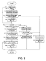
- FIG. 2 is a flowchart illustrating DPF regeneration control by the control unit 20, which may be repeatedly exercised at a predetermined time.
- step S1 controller 20 determines a value of a regeneration flag, and if the value is 0 (nonregenerative), the controller estimates the particulate sediment in the DPF 13 (C) in step S2.
- the controller 20 may detect the differential pressure in the DPF 13 ⁇ P by reading signals from the differential pressure sensor 25. Controller 20 estimates flow rate of exhaust emission SV by referring to a known function based on the amount of the intake air Qa detected by the air flow meter 23, and the reading of the injection quantity Qf to a fuel injection valve 9. Controller 20 estimates particulate sediment in the DPF 13 based on the differential pressure ⁇ P in the DPF and the flow rate of exhaust emission SV. The more the differential pressure in the DPF increases, the larger the estimated amount of particulate sediment becomes because the amount of particulate sediment captured in the DPF 13 increases. However, the differential pressure in the DPF varies according to the flow rate of exhaust emission. If the amount of particulate sediment remains constant, the differential pressure in the DPF increases as the flow rate of exhaust emission increases. The controller 20 corrects the estimated amount of particulate sediment based on the flow rate of exhaust emission.
- controller 20 compares the amount of particulate sediment estimated in S2 with the prescribed "particulate sediment high" value (hereinafter referred to as "#PSH") to determine whether or not the estimated amount of particulate sediment is greater than or equal to #PSH.
- #PSH the prescribed "particulate sediment high” value
- the controller 20 determines regeneration is not currently required, thereafter S 14 is followed to perform a normal control (normal lean combustion in a diesel engine).
- the controller 20 determines that regeneration is required; thereafter S4 is followed.
- the controller 20 sets the regeneration flag to 1, thereafter S5 is followed. If the regeneration flag is also determined to be 1 (during regeneration) in S1, thereafter S5 is followed.
- Controller 20 determines whether or not the regeneration conditions meet the regeneration conditions: if the engine driving mode is in idle drive, slow-speed drive, and ultra-low-speed drive (for example, less than 20km/h), controller 20 determines that the regeneration conditions are not established, thereafter S11 is followed. In other engine driving modes, controller 20 determines that the regeneration conditions are established; thereafter S6 and S7 are followed to regenerate the DPF 13.
- controller 20 changes combustion from a normal lean combustion in a diesel engine to a divided, retarded combustion.
- the divided, retarded combustion includes a main or primary combustion to generate engine torque and at least one preliminary combustion prior to the main combustion. At least one of the preliminary combustions requires fuel injection to occur on the compression stroke.
- the main combustion requires fuel injection to start after the preliminary combustion is completed.
- the controller 20 sets the air/fuel ratio (the value is represented as " ⁇ ") to be comparatively rich (for example, ⁇ ⁇ 0.9 to 1.4).
- the exhaust ⁇ should be controlled from approximately 0.9 to 1.4, and the temperature of the DPF should be raised to approximately 600 degrees Celsius or more.
- the controller 20 controls the fuel injection amount and the air throttle 5 to adjust the air amount taken in the combustion chamber.
- controller 20 implements fuel injection (a,b) for the divided, retarded combustion to promote a main combustion to generate the main torque, and a preliminary combustion prior to the main combustion by dividing the main injection.
- the preliminary combustion occurs close to the top dead center (hereinafter referred to as "TDC"), and the main combustion starts after the preliminary combustion is completed.
- fuel is injected on the compression stroke (a), which creates a preliminary combustion to raise the cylinder temperature (temperature of the pressure connector) close to TDC.
- the injection quantity to generate heat in the preliminary combustion depends on the operating conditions.
- the fuel injected during preliminary combustion maintains a cylinder temperature that exceeds the temperature at which autoignition can happen during fuel injection for the main combustion.
- the stability of the preliminary combustion can be improved by changing the fuel injection quantity and timing for the preliminary combustion depending on the temperature of the pressure connector estimated under each operating condition.
- controller 20 While improving the controllability for the target temperature with expanding the retard limitations by raising the cylinder temperature with the preliminary combustion, controller 20 also controls smoke emission with the ignition delay time for the main combustion, and raising the premix combustion ratio of the main combustion by injecting the fuel for the main combustion after the entire preliminary combustion is completed.
- the interval between the commencing time of the preliminary combustion and that of the main combustion depends on the engine rotations.
- the interval may be at least 20° crank angle (CA) for the preliminary combustion (heat generation caused by the preliminary combustion) to be completed.
- CA crank angle
- smoke deterioration can be prevented by preventing the main combustion from deteriorating.
- the combustion speed is extremely slow because the main combustion starts during the expansion stroke, and the main combustion is completed after 50° after TDC.
- Delaying the termination time of the main combustion makes the main combustion slower, which may prevent increased combustion noise.
- Such divided, retarded combustion can occur at high emission temperatures and with low smoke under rich conditions, and hydrocarbon emissions are low.
- the combustion under low ⁇ conditions becomes stable, and high exhaust temperature can be secured even if the injection timing of the main injection is retarded because the retard limitations of the main combustion are expanded by the preliminary combustion.
- controller 20 can achieve low smoke and high exhaust temperature with a plurality of preliminary combustions even under low load conditions.
- controller 20 compares the amount of particulate sediment estimated in S8 with the prescribed "particulate sediment low” value (hereinafter referred to as "#PSL") to determine the completion of regeneration to determine whether or not the estimated amount of particulate sediment ⁇ #PSL.
- #PSL the prescribed "particulate sediment low” value
- controller 20 determines regeneration is not complete, and regeneration continues.
- controller 20 determines that regeneration is complete; thereafter S10 is followed to return by resetting the regeneration flag to 0.
- controller 20 determines whether or not DPF temperature Tdpf is lower than the prescribed temperature #TMP. This occurs where the temperature of the DPF 13 is lowered enough when regeneration of the DPF 13 has not been commenced, or by discontinuance of regeneration control.
- Figure 3 is a flowchart for a sub routine of the discontinuance of regeneration control to be executed in S13 of the process in Figure 2 .
- one of two engine operations is selected depending on the conditions of the DPF 13.
- the first engine operation is an operation with higher heat released from the DPF 13 (quantity of the negative heat transfer between the DPF 13 and exhaust emission) than the second engine operation, In other words, the exhaust temperature entering the filter is so low that there is a high oxygen surplus- to put it simply, it is a lean operation.
- the DPF 13 is cooled by the exhaust emission so that the heat released from the DPF 13 will be higher because the temperature of the exhaust emission is low.
- the heating value in the DPF 13 may be higher than the heat released because of an oxygen surplus depending on the conditions of the DPF 13.
- the second engine operation is an operation with lower heating value in the DPF 13 (heat quantity by an oxidation reaction arising from burning particulate accumulating in the DPF 13) than the first engine operation.
- the exhaust temperature entering the filter is so high that there is a low oxygen surplus, to put it simply, it is a rich operation.
- the heating value in the DPF 13 becomes low because there is a low oxygen surplus.
- the heat released from the DPF 13 may be lower than the heating value depending on the conditions of the DPF 13 because the exhaust temperature is high.
- the first and second engine operations In comparison with the divided, retarded combustion under low ⁇ conditions used for regeneration, the first and second engine operations have normal injection timing (close to TDC) in the diesel engine without dividing the main injection, and retarding the injection timing.
- normal operation of the engine 1 uses a lean air/fuel ratio
- regeneration of the DPF 13 requires a much richer air/fuel ratio.
- the first and second engine operations require air/fuel ratios within the range of an air/fuel ratio for normal operation and an air/fuel ratio for regeneration of the DPF 13.
- the first engine operation uses an air/fuel ratio as rich or richer than the normal lean combustion in the diesel engine, but leaner than the divided, retarded combustion during regeneration.
- the second engine operation also uses an air/fuel ratio as lean as, or leaner than the divided, retarded combustion during regeneration, but richer than the first engine operation and normal lean combustion.
- Temperature Tdpf of the DPF 13 is estimated in S101 just as in S11. Particulate sediment C in the DPF 13 is also estimated just as S2,S8.
- the flow rate of exhaust emission SV is estimated by the amount of the intake air Qa detected by the air flow meter 23, and the reading of the injection quantity Qf to a fuel injection valve 9.
- Equation 2 k is the reaction rate constant, Ea is the activation energy constant, R is the gas constant, Tdpf is the DPF temperature, C is the amount of particulate sediment and O is the oxygen concentration of the exhaust emission entering the PDF.
- a heat budget of the first engine operation (the difference between the heating value QGEN1 and the heat released QRAD1, equal to QGEN1 - QRAD1, is estimated; and a heat budget in the case of the second engine operation, equal to QGEN2 - QRAD2 is estimated.
- These heat budgets will show the trend of rising temperature in the case of each operation. If the heat budget is positive, the temperature of the DPF 13 will rise; and if it is negative, the temperature of the DPF 13 will fall.
- the DPF 13 can be controlled toward the direction where the temperature of the DPF 13 will further fall so that overheating of the filter can be avoided, by selecting either one of the two engine operations between the first engine operation with higher heat released from the DPF 13 (quantity of the negative heat transfer between the DPF 13 and exhaust emission), and the second engine operation is an operation with lower heating value in the DPF 13 (heat quantity by an oxidation reaction arising from burning particulate accumulating in the DPF 13) depending on the conditions of the DPF 13.
- the first engine operation uses a lower exhaust temperature entering the DPF 13 and a high oxygen surplus (lean operation); and the second engine operation is an operation with higher exhaust temperature entering the DPF 13 and a low oxygen surplus (rich operation). Both operations can be carried out by control unit 20 by controlling the fuel injection amount and fuel injection timing, opening into the inlet air throttle 5, opening the EGR valve 12, and nozzle-opening into a variable-nozzle mechanism 15 of the supercharger 3.
- the conditions of the DPF 13 can be determined with precision by determining based on the temperature of the DPF 13 and particulate sediment in the DPF 13.
- the conditions of the DPF 13 can be determined with precision by calculating the heat quantity by an oxidation reaction arising from burning particulate accumulating in the DPF13, and the quantity of the negative heat transfer between the DPF13 and exhaust emission in the case of the first and the second engine operations respectively based on the temperature of the DPF 13 and particulate sediment in the DPF 13.
- the temperature of the DPF 13 can be lowered by comparing the heat budget of the first engine operation, and the heat budget of the second engine operation, and by selecting the operation with the lowest heat budget.
- the heat quantity by an oxidation reaction arising from burning particulate accumulating in the DPF 13 can be predicted with precision by predicting the temperature of the DPF 13 (Tdpf), particulate sediment in the DPF 13 (C), and the oxygen concentration of the exhaust emission entering the DPF (O).
- the quantity of the negative heat transfer between the DPF 13 and exhaust emission can be predicted with precision by predicting the temperature of the DPF 13 (Tdpf), temperature of the exhaust emission entering the DPF (Tgas), and the flow rate of the exhaust emission entering the DPF 13 (SV).
- the temperature of the DPF 13 can be predicted with precision by measuring the exhaust temperature detected by the exhaust temperature sensors 26,27 provided on both the filter inlet and the filter outlet sides.
- the particulate sediment in the DPF 13 (C) can be predicted with precision by measuring the differential pressure in the DPF 13 ⁇ P, and the flow rate of the exhaust emission entering the DPF 13 (SV).
- the oxygen concentration of the exhaust emission entering the DPF (O) can be easily reduced to practice by determining based on type of operations, the first and the second respectively.
- the temperature of the exhaust emission entering the DPF can be easily determined by determining based on type of operations, the first and the second respectively.
- the flow rate of the exhaust emission entering the DPF 13 (SV) can be predicted by predicting the detected value of an air flow meter 21 provided in an engine inlet system, and the reading of the injection quantity Qf to a fuel injection valve 9.
Landscapes
- Engineering & Computer Science (AREA)
- Chemical & Material Sciences (AREA)
- Combustion & Propulsion (AREA)
- Mechanical Engineering (AREA)
- General Engineering & Computer Science (AREA)
- Processes For Solid Components From Exhaust (AREA)
- Filtering Of Dispersed Particles In Gases (AREA)
- Electrical Control Of Air Or Fuel Supplied To Internal-Combustion Engine (AREA)
Claims (13)
- Verbrennungsmotor, der Folgendes umfasst:ein Filtermittel zum Auffangen von Partikeln im Motorabgas;ein Drosselmittel zum Regeln einer Menge von Ansaugluft in den Motor;ein Einspritzmittel zum Zuführen von Kraftstoff an den Verbrennungsmotor; undein Regelungsmittel zum Regeln der Ansaugluftmenge und einer Kraftstoffeinspritzmenge, wenn die Regenerierung des Filtermittels erforderlich ist;dadurch gekennzeichnet, dass das Regelungsmittel dazu angeordnet ist, wenn die Bedingungen von vorgeschriebenen Regenerierungsbedingungen während der Regenerierung des Filtermittels abweichen, zu wählen zwischen:einem ersten Motorbetrieb mit einem ersten Luft-Kraftstoff-Verhältnis, der die Wärmeübertragung vom Filtermittel zum Motorabgas erhöht; undeinem zweiten Motorbetrieb mit einem zweiten Luft-Kraftstoff-Verhältnis, der die Partikelverbrennung im Filtermittel begrenzt.
- Motor nach Anspruch 1, wobei der erste Motorbetrieb dazu angeordnet ist, eine erste Abgastemperatur und einen ersten Sauerstoffüberschuss bereitzustellen und der zweite Motorbetrieb dazu angeordnet ist, eine zweite Abgastemperatur und einen zweiten Sauerstoffüberschuss bereitzustellen, und
wobei die erste Abgastemperatur niedriger ist als die zweite Abgastemperatur und der erste Sauerstoffüberschuss höher ist als der zweite Sauerstoffüberschuss. - Motor nach Anspruch 1 oder Anspruch 2, wobei das Regelungsmittel dazu angeordnet ist, einen des ersten Motorbetriebs und des zweiten Motorbetriebs als eine Funktion einer Temperatur des Filtermittels und einer Menge von Partikelablagerung im Filtermittel zu wählen.
- Motor nach einem der vorangehenden Ansprüche, wobei das Regelungsmittel dazu angeordnet ist, einen des ersten Motorbetriebs und des zweiten Motorbetriebs als eine Funktion eines, dem ersten Motorbetrieb entsprechenden, ersten Wärmebudgets und eines, dem zweiten Motorbetrieb entsprechenden, zweiten Wärmebudgets zu wählen,
wobei das erste Wärmebudget eine erste Wärmemenge von einer ersten Oxidationsreaktion brennender angesammelter Partikel im Filtermittel und eine erste Menge negativer Wärmeübertragung zwischen dem Filtermittel und dem Abgas umfasst, und
wobei das zweite Wärmebudget eine zweite Wärmemenge von einer zweiten Oxidationsreaktion brennender angesammelter Partikel im Filtermittel und eine zweite Menge negativer Wärmeübertragung zwischen dem Filtermittel und dem Abgas umfasst. - Motor nach Anspruch 4, wobei das Regelungsmittel dazu angeordnet ist, einen des ersten Motorbetriebs und des zweiten Motorbetriebs durch Vergleichen des ersten Wärmebudgets und des zweiten Wärmebudgets zu wählen und den Betrieb mit dem niedrigsten entsprechenden Wärmebudget zu wählen.
- Motor nach Anspruch 4 oder Anspruch 5, wobei das Regelungsmittel dazu angeordnet ist, die erste Wärmemenge in Abhängigkeit von einer Temperatur des Filtermittels, einer Menge von Partikelablagerung im Filtermittel und einer Sauerstoffkonzentration im in das Filtermittel eintretenden Abgas zu berechnen.
- Motor nach Anspruch 6, wobei das Regelungsmittel dazu angeordnet ist, die Temperatur des Filtermittels unter Verwendung von Eingängen von einem ersten Abgastemperatursensor an einer Einlassseite des Filtermittels und einem zweiten Abgastemperatursensor an einer Auslassseite des Filtermittels zu berechnen.
- Motor nach Anspruch 6 oder Anspruch 7, wobei das Regelungsmittel dazu angeordnet ist, die Menge der Partikelablagerung im Filtermittel in Abhängigkeit von einem Differentialdruck des Filtermittels und einer Strömungsgeschwindigkeit des Abgases zu berechnen.
- Motor nach einem der Ansprüche 4 bis 8, wobei das Regelungsmittel dazu angeordnet ist, die erste Menge von negativer Wärmeübertragung in Abhängigkeit von einer Temperatur des Filtermittels, einer in das Filtermittel eintretenden Abgastemperatur und einer Strömungsgeschwindigkeit des Abgases zu berechnen.
- Verfahren, das Folgendes umfasst:Bestimmen, ob Bedingungen von den vorgeschriebenen Regenerierungsbedingungen während der Regenerierung eines Abgaspartikelfilters abweichen; undals Reaktion auf die Bestimmung, wählen zwischen:einem ersten Motorbetrieb mit einem ersten Luft-Kraftstoff Verhältnis, der die Wärmeübertragung vom Filter zum durch den Filter strömenden Abgas erhöht; undeinem zweiten Motorbetrieb mit einem zweiten Luft-Kraftstoff-Verhältnis, der die Partikelverbrennung im Filter begrenzt.
- Verfahren nach Anspruch 10, das weiter Folgendes umfasst:Bestimmen einer Temperatur des Filters; undBestimmen einer Menge von Partikelablagerung im Filter, wobei die Wahl eines des ersten Motorbetriebs und des zweiten Motorbetriebs abhängig ist von der Temperatur des Filters und der Menge der Partikelablagerung im Filter.
- Verfahren nach Anspruch 10 oder 11, das weiter Folgendes umfasst:Berechnen eines ersten Wärmebudgets mit einer ersten Wärmemenge von einer ersten Oxidationsreaktion brennender angesammelter Partikel im Filter und einer ersten Menge negativer Wärmeübertragung zwischen dem Filter und dem Abgas, das dem ersten Motorbetrieb entspricht; undBerechnen eines zweiten Wärmebudgets mit einer zweiten Wärmemenge von einer zweiten Oxidationsreaktion brennender angesammelter Partikel im Filter und einer zweiten Menge negativer Wärmeübertragung zwischen dem Filter und dem Abgas, das dem zweiten Motorbetrieb entspricht;wobei die Wahl eines des ersten Motorbetriebs und des zweiten Motorbetriebs abhängig ist vom ersten Wärmebudget und vom zweiten Wärmebudget.
- Fahrzeug oder System mit einem Motor nach einem der Ansprüche 1 bis 9 oder einer Regelungseinheit zum Ausführen des Verfahrens nach einem der Ansprüche 10 bis 12.
Applications Claiming Priority (1)
| Application Number | Priority Date | Filing Date | Title |
|---|---|---|---|
| JP2004364479A JP4595521B2 (ja) | 2004-12-16 | 2004-12-16 | 内燃機関の排気浄化装置 |
Publications (2)
| Publication Number | Publication Date |
|---|---|
| EP1672204A1 EP1672204A1 (de) | 2006-06-21 |
| EP1672204B1 true EP1672204B1 (de) | 2008-07-23 |
Family
ID=36118310
Family Applications (1)
| Application Number | Title | Priority Date | Filing Date |
|---|---|---|---|
| EP05257775A Expired - Lifetime EP1672204B1 (de) | 2004-12-16 | 2005-12-16 | Brennkraftmaschine mit Partikelfiter für Abgase |
Country Status (5)
| Country | Link |
|---|---|
| US (1) | US7293410B2 (de) |
| EP (1) | EP1672204B1 (de) |
| JP (1) | JP4595521B2 (de) |
| CN (1) | CN100453775C (de) |
| DE (1) | DE602005008350D1 (de) |
Cited By (1)
| Publication number | Priority date | Publication date | Assignee | Title |
|---|---|---|---|---|
| CN110114569A (zh) * | 2017-03-08 | 2019-08-09 | 宝马股份公司 | 用于适配交通工具排放的控制单元 |
Families Citing this family (13)
| Publication number | Priority date | Publication date | Assignee | Title |
|---|---|---|---|---|
| US8104270B2 (en) * | 2007-05-15 | 2012-01-31 | GL Global Technology Operations LLC | Electrically heated particulate filter preparation methods and systems |
| US8291694B2 (en) * | 2007-06-15 | 2012-10-23 | GM Global Technology Operations LLC | Electrically heated particulate filter enhanced ignition strategy |
| US8151557B2 (en) * | 2007-08-07 | 2012-04-10 | GM Global Technology Operations LLC | Electrically heated DPF start-up strategy |
| US8505278B2 (en) * | 2009-04-30 | 2013-08-13 | Cummins Ip, Inc. | Engine system properties controller |
| US8356471B2 (en) * | 2008-12-05 | 2013-01-22 | Cummins Ip, Inc. | Apparatus, system, and method for controlling reductant dosing in an SCR catalyst system |
| US8146351B2 (en) * | 2009-06-05 | 2012-04-03 | GM Global Technology Operations LLC | Regeneration systems and methods for particulate filters using virtual brick temperature sensors |
| DE112010003613T5 (de) * | 2009-09-10 | 2012-11-08 | Cummins Ip, Inc. | Niedertemperatur-Katalysator für die selektive katalytische Reduktion sowie dazugehörige Systeme und Verfahren |
| US8424290B2 (en) * | 2010-02-26 | 2013-04-23 | GM Global Technology Operations LLC | Method and system for controlling an engine during diesel particulate filter regeneration at idle conditions |
| US8733083B2 (en) | 2010-04-26 | 2014-05-27 | Cummins Filtration Ip, Inc. | SCR catalyst ammonia surface coverage estimation and control |
| JP5304738B2 (ja) * | 2010-06-25 | 2013-10-02 | 日産自動車株式会社 | ディーゼルエンジンの排気浄化装置 |
| JP5287940B2 (ja) * | 2011-06-29 | 2013-09-11 | トヨタ自動車株式会社 | 内燃機関の排気浄化装置 |
| US9824505B2 (en) * | 2014-02-25 | 2017-11-21 | Ford Global Technologies, Llc | Method for triggering a vehicle system monitor |
| US11867111B2 (en) | 2019-05-09 | 2024-01-09 | Cummins Emission Solutions Inc. | Valve arrangement for split-flow close-coupled catalyst |
Family Cites Families (16)
| Publication number | Priority date | Publication date | Assignee | Title |
|---|---|---|---|---|
| JPS60206924A (ja) * | 1984-03-31 | 1985-10-18 | Mitsubishi Motors Corp | デイ−ゼルパテイキユレ−ト捕集部材保護装置 |
| CN1230608C (zh) * | 2000-07-24 | 2005-12-07 | 丰田自动车株式会社 | 尾气净化装置 |
| JP2002089327A (ja) | 2000-09-14 | 2002-03-27 | Nissan Motor Co Ltd | 内燃機関の排気浄化装置 |
| EP1203869B1 (de) | 2000-11-03 | 2002-08-21 | Ford Global Technologies, Inc., A subsidiary of Ford Motor Company | Regelungsanordnung und Verfahren zur Unterbrechung der Regeneration eines Partikelfilters eines Dieselmotors |
| JP2002285825A (ja) * | 2001-03-27 | 2002-10-03 | Isuzu Ceramics Res Inst Co Ltd | ディーゼルパティキュレートフィルタ装置の制御方法 |
| JP3959600B2 (ja) * | 2001-07-18 | 2007-08-15 | 三菱ふそうトラック・バス株式会社 | 内燃機関の排気浄化装置 |
| CN1535351A (zh) * | 2001-07-26 | 2004-10-06 | �����Զ�����ҵ��ʽ���� | 排气净化装置 |
| FR2830274B1 (fr) | 2001-09-28 | 2004-05-28 | Renault | Procede de regeneration d'un filtre a particules pour moteur a combustion interne |
| JP2003193310A (ja) | 2001-12-19 | 2003-07-09 | Toray Ind Inc | 裏 地 |
| US6915629B2 (en) * | 2002-03-07 | 2005-07-12 | General Motors Corporation | After-treatment system and method for reducing emissions in diesel engine exhaust |
| JP4075573B2 (ja) * | 2002-06-13 | 2008-04-16 | 株式会社デンソー | 内燃機関の排ガス浄化装置 |
| JP4092464B2 (ja) | 2002-06-28 | 2008-05-28 | 日産自動車株式会社 | 排気浄化装置 |
| JP4161887B2 (ja) * | 2002-11-29 | 2008-10-08 | 日産自動車株式会社 | 排気浄化装置 |
| JP4228690B2 (ja) * | 2002-12-25 | 2009-02-25 | 日産自動車株式会社 | 内燃機関の排気浄化装置 |
| US6988361B2 (en) * | 2003-10-27 | 2006-01-24 | Ford Global Technologies, Llc | Method and system for controlling simultaneous diesel particulate filter regeneration and lean NOx trap desulfation |
| JP2005155500A (ja) | 2003-11-26 | 2005-06-16 | Toyota Motor Corp | 内燃機関の排気浄化装置 |
-
2004
- 2004-12-16 JP JP2004364479A patent/JP4595521B2/ja not_active Expired - Fee Related
-
2005
- 2005-12-15 US US11/304,069 patent/US7293410B2/en not_active Expired - Fee Related
- 2005-12-16 EP EP05257775A patent/EP1672204B1/de not_active Expired - Lifetime
- 2005-12-16 DE DE602005008350T patent/DE602005008350D1/de not_active Expired - Lifetime
- 2005-12-16 CN CNB2005101317537A patent/CN100453775C/zh not_active Expired - Fee Related
Cited By (2)
| Publication number | Priority date | Publication date | Assignee | Title |
|---|---|---|---|---|
| CN110114569A (zh) * | 2017-03-08 | 2019-08-09 | 宝马股份公司 | 用于适配交通工具排放的控制单元 |
| CN110114569B (zh) * | 2017-03-08 | 2022-03-01 | 宝马股份公司 | 用于适配交通工具排放的控制单元 |
Also Published As
| Publication number | Publication date |
|---|---|
| CN1789677A (zh) | 2006-06-21 |
| EP1672204A1 (de) | 2006-06-21 |
| JP4595521B2 (ja) | 2010-12-08 |
| JP2006170093A (ja) | 2006-06-29 |
| DE602005008350D1 (de) | 2008-09-04 |
| US20060144038A1 (en) | 2006-07-06 |
| CN100453775C (zh) | 2009-01-21 |
| US7293410B2 (en) | 2007-11-13 |
Similar Documents
| Publication | Publication Date | Title |
|---|---|---|
| US7054734B2 (en) | Combustion control system of internal combustion engine | |
| US6758037B2 (en) | Exhaust emission control device of engine | |
| US7100365B2 (en) | Combustion control system of internal combustion engine | |
| US8156730B2 (en) | Engine performance management during a diesel particulate filter regeneration event | |
| EP1412622B1 (de) | Verfahren zur aufheizung eines katalysators eines abgasnachbehandlungssystems | |
| JP6217398B2 (ja) | ディーゼルエンジンの燃料噴射制御装置 | |
| RU2435043C2 (ru) | Способ управления регенерацией очистительной системы и устройство для его осуществления | |
| US7891174B2 (en) | Management of regeneration of a diesel particulate filter | |
| US7640727B2 (en) | Combustion control for engine | |
| EP1672204B1 (de) | Brennkraftmaschine mit Partikelfiter für Abgase | |
| US6907862B2 (en) | Combustion control apparatus for internal combustion engine | |
| WO2014196036A1 (ja) | 内燃機関の制御装置 | |
| US7121083B2 (en) | Combustion control apparatus and method for internal combustion engine | |
| JP2005023850A (ja) | 内燃機関の空燃比制御装置 | |
| EP1650419B1 (de) | Steuerverfahren für das Luft-/Kraftstoffverhältnis | |
| CN111946480A (zh) | 一种发动机后处理控制方法 | |
| US12253043B2 (en) | Thermal management of exhaust gas with HCCI event | |
| EP0992667A2 (de) | Brennkraftmaschine | |
| JP5045482B2 (ja) | 排気浄化装置及び排気浄化方法 | |
| EP1496224B1 (de) | Steuergerät für die Verbrennung einer Brennkraftmaschine | |
| JP6740744B2 (ja) | エンジンの制御装置 | |
| JP2010190119A (ja) | ディーゼルエンジンの燃焼制御装置 |
Legal Events
| Date | Code | Title | Description |
|---|---|---|---|
| PUAI | Public reference made under article 153(3) epc to a published international application that has entered the european phase |
Free format text: ORIGINAL CODE: 0009012 |
|
| AK | Designated contracting states |
Kind code of ref document: A1 Designated state(s): AT BE BG CH CY CZ DE DK EE ES FI FR GB GR HU IE IS IT LI LT LU LV MC NL PL PT RO SE SI SK TR |
|
| AX | Request for extension of the european patent |
Extension state: AL BA HR MK YU |
|
| 17P | Request for examination filed |
Effective date: 20061221 |
|
| 17Q | First examination report despatched |
Effective date: 20070126 |
|
| AKX | Designation fees paid |
Designated state(s): DE FR GB |
|
| GRAP | Despatch of communication of intention to grant a patent |
Free format text: ORIGINAL CODE: EPIDOSNIGR1 |
|
| GRAS | Grant fee paid |
Free format text: ORIGINAL CODE: EPIDOSNIGR3 |
|
| GRAA | (expected) grant |
Free format text: ORIGINAL CODE: 0009210 |
|
| AK | Designated contracting states |
Kind code of ref document: B1 Designated state(s): DE FR GB |
|
| REG | Reference to a national code |
Ref country code: GB Ref legal event code: FG4D |
|
| REF | Corresponds to: |
Ref document number: 602005008350 Country of ref document: DE Date of ref document: 20080904 Kind code of ref document: P |
|
| PLBE | No opposition filed within time limit |
Free format text: ORIGINAL CODE: 0009261 |
|
| STAA | Information on the status of an ep patent application or granted ep patent |
Free format text: STATUS: NO OPPOSITION FILED WITHIN TIME LIMIT |
|
| 26N | No opposition filed |
Effective date: 20090424 |
|
| PGFP | Annual fee paid to national office [announced via postgrant information from national office to epo] |
Ref country code: GB Payment date: 20131211 Year of fee payment: 9 Ref country code: DE Payment date: 20131211 Year of fee payment: 9 |
|
| PGFP | Annual fee paid to national office [announced via postgrant information from national office to epo] |
Ref country code: FR Payment date: 20131209 Year of fee payment: 9 |
|
| REG | Reference to a national code |
Ref country code: DE Ref legal event code: R119 Ref document number: 602005008350 Country of ref document: DE |
|
| GBPC | Gb: european patent ceased through non-payment of renewal fee |
Effective date: 20141216 |
|
| REG | Reference to a national code |
Ref country code: FR Ref legal event code: ST Effective date: 20150831 |
|
| PG25 | Lapsed in a contracting state [announced via postgrant information from national office to epo] |
Ref country code: GB Free format text: LAPSE BECAUSE OF NON-PAYMENT OF DUE FEES Effective date: 20141216 Ref country code: DE Free format text: LAPSE BECAUSE OF NON-PAYMENT OF DUE FEES Effective date: 20150701 |
|
| PG25 | Lapsed in a contracting state [announced via postgrant information from national office to epo] |
Ref country code: FR Free format text: LAPSE BECAUSE OF NON-PAYMENT OF DUE FEES Effective date: 20141231 |