EP1674010B1 - Aspirateur avec dispositif de retenue pour un ensemble d'aspiration - Google Patents
Aspirateur avec dispositif de retenue pour un ensemble d'aspiration Download PDFInfo
- Publication number
- EP1674010B1 EP1674010B1 EP05109188A EP05109188A EP1674010B1 EP 1674010 B1 EP1674010 B1 EP 1674010B1 EP 05109188 A EP05109188 A EP 05109188A EP 05109188 A EP05109188 A EP 05109188A EP 1674010 B1 EP1674010 B1 EP 1674010B1
- Authority
- EP
- European Patent Office
- Prior art keywords
- vacuum cleaner
- base
- parking
- cleaner according
- main body
- Prior art date
- Legal status (The legal status is an assumption and is not a legal conclusion. Google has not performed a legal analysis and makes no representation as to the accuracy of the status listed.)
- Expired - Lifetime
Links
Images


Classifications
-
- A—HUMAN NECESSITIES
- A47—FURNITURE; DOMESTIC ARTICLES OR APPLIANCES; COFFEE MILLS; SPICE MILLS; SUCTION CLEANERS IN GENERAL
- A47L—DOMESTIC WASHING OR CLEANING; SUCTION CLEANERS IN GENERAL
- A47L9/00—Details or accessories of suction cleaners, e.g. mechanical means for controlling the suction or for effecting pulsating action; Storing devices specially adapted to suction cleaners or parts thereof; Carrying-vehicles specially adapted for suction cleaners
-
- A—HUMAN NECESSITIES
- A47—FURNITURE; DOMESTIC ARTICLES OR APPLIANCES; COFFEE MILLS; SPICE MILLS; SUCTION CLEANERS IN GENERAL
- A47L—DOMESTIC WASHING OR CLEANING; SUCTION CLEANERS IN GENERAL
- A47L5/00—Structural features of suction cleaners
- A47L5/12—Structural features of suction cleaners with power-driven air-pumps or air-compressors, e.g. driven by motor vehicle engine vacuum
- A47L5/22—Structural features of suction cleaners with power-driven air-pumps or air-compressors, e.g. driven by motor vehicle engine vacuum with rotary fans
- A47L5/36—Suction cleaners with hose between nozzle and casing; Suction cleaners for fixing on staircases; Suction cleaners for carrying on the back
- A47L5/362—Suction cleaners with hose between nozzle and casing; Suction cleaners for fixing on staircases; Suction cleaners for carrying on the back of the horizontal type, e.g. canister or sledge type
-
- A—HUMAN NECESSITIES
- A47—FURNITURE; DOMESTIC ARTICLES OR APPLIANCES; COFFEE MILLS; SPICE MILLS; SUCTION CLEANERS IN GENERAL
- A47L—DOMESTIC WASHING OR CLEANING; SUCTION CLEANERS IN GENERAL
- A47L9/00—Details or accessories of suction cleaners, e.g. mechanical means for controlling the suction or for effecting pulsating action; Storing devices specially adapted to suction cleaners or parts thereof; Carrying-vehicles specially adapted for suction cleaners
- A47L9/0009—Storing devices ; Supports, stands or holders
- A47L9/0018—Storing devices ; Supports, stands or holders integrated in or removably mounted upon the suction cleaner for storing parts of said suction cleaner
- A47L9/0027—Storing devices ; Supports, stands or holders integrated in or removably mounted upon the suction cleaner for storing parts of said suction cleaner specially adapted for holding the suction cleaning tools
-
- A—HUMAN NECESSITIES
- A47—FURNITURE; DOMESTIC ARTICLES OR APPLIANCES; COFFEE MILLS; SPICE MILLS; SUCTION CLEANERS IN GENERAL
- A47L—DOMESTIC WASHING OR CLEANING; SUCTION CLEANERS IN GENERAL
- A47L9/00—Details or accessories of suction cleaners, e.g. mechanical means for controlling the suction or for effecting pulsating action; Storing devices specially adapted to suction cleaners or parts thereof; Carrying-vehicles specially adapted for suction cleaners
- A47L9/009—Carrying-vehicles; Arrangements of trollies or wheels; Means for avoiding mechanical obstacles
Definitions
- the present invention relates to a vacuum cleaner, and more particularly, to a parking device for a nozzle of a vacuum cleaner for use on a vacuum cleaner having more than one base.
- the inventive parking device allows a nozzle portion including an extension tube to be hooked onto the floor portion of the vacuum cleaner, thereby facilitating storage and transportation of the vacuum cleaner.
- a vacuum cleaner is used to clean a room or other spaces by sucking air containing foreign objects and filtering the foreign object using vacuum pressure generated therein.
- a dust collection unit with a filtering unit is provided in the vacuum cleaner.
- the filtering unit is classified into a porous filter formed of porous material and a cyclone type filter.
- the porous filter formed of porous material is designed to filter the foreign objects contained in air while the air passes through the filter.
- the cyclone type filter is designed to filter the foreign objects using cyclone airflow.
- a user cleans the filter to remove the foreign objects clogged in the filter.
- the porous filter cannot be reused. Since the cyclone type filter is designed to remove the foreign objects from the air by a rotational air current generated by cyclone airflow, the clogging of the foreign objects in the filter is not incurred. Due to this reason, in recent years, cyclone type filter has been widely used.
- the nozzle portion When a vacuum cleaner is stored or moved, the nozzle portion is parked on the main body of the vacuum cleaner, allowing easy storage and transport of the vacuum cleaner.
- the parking position is generally located on the bottom or the rear of the main body of the vacuum cleaner.
- a parking portion located at the front of a main body of the vacuum cleaner tends to be structurally weak and therefore easily damaged, preventing its performance of its given task.
- US-A-5125127 discloses a holding device for a suction tube nozzle unit on an electrical vacuum cleaner.
- the vacuum cleaner has a base defining a lower floor portion of a main body of the vacuum cleaner.
- an opening into which a hook portion attached to the suction tube nozzle unit can be engaged to mount the suction tube nozzle unit to the base.
- a spring arm Inside the base is provided a spring arm that, simultaneously with the engaging of the hook portion into the opening, is slided and thereby pivots a retaining clip outward from the base serving to hold the suction tube of the suction tube nozzle unit at a further position.
- US-A-4545089 discloses a type of vacuum cleaner which always stands on a suction assembly.
- the vacuum cleaner housing has a pocket for nesting an accessory appliance like a separate mobile handheld vacuum cleaner.
- a latch mechanism maintains the accessory appliance within the pocket and is releasable to permit removal of the accessory appliance.
- the latch mechanism is supported on a separate intermediate wall and only a latch catch thereof protrudes through an opening in the housing outer wall at the pocket and engages a recess of the accessory appliance.
- the present invention is directed to a vacuum cleaner with a suction assembly parking device that substantially obviates one or more problems due to limitations and disadvantages of the related art.
- An object of the present invention is to provide a vacuum cleaner and a strong parking device for a nozzle of a vacuum cleaner located on the underside of the vacuum cleaner.
- An aspect of the present invention is to provide a vacuum cleaner and a parking device for a nozzle of a vacuum cleaner capable of firmly reinforcing a multi-level base of a vacuum cleaner (as is the case with vacuum cleaners employing multi cyclone dust collection units).
- the parking device for a nozzle of a vacuum cleaner according to the present invention provides increased structural strength strength and durability of the vacuum cleaner.
- FIG. 1 is a perspective view of a vacuum cleaner where a dust collection unit of the present invention can be employed
- FIG. 2 is a front perspective of a vacuum cleaner depicted in FIG. 1 ;
- FIG. 3 is a perspective view illustrating a vacuum cleaner and a dust collection unit according to an embodiment of the present invention, which is separated from the vacuum cleaner;
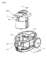
- FIG. 4 is an exploded perspective view of a main body of a vacuum cleaner where a dust collection unit according to an embodiment of the present invention is employed;
- FIG. 5 is a frontal perspective view of a base of a vacuum cleaner according to an embodiment of the present invention.
- FIG. 6 is a frontal perspective view of a base divided into a first base and a second base
- FIG. 7 is a sectional view taken along lines II-II' of FIG. 5 ;
- FIG. 8 is an exploded perspective view of a dust collection unit according to the present invention.
- FIG. 9 is a sectional view taken along lines I-I' of FIG. 3 ;
- FIG. 10 is a sectional view of a vacuum cleaner where a dust collection unit according to an embodiment of the present invention is provided.
- FIG. 1 shows a vacuum cleaner to which a dust collection unit according to the present invention can be applied.
- a vacuum cleaner includes a main body 100 and a suction assembly connected to a suction portion through which outer air is sucked into the main body 100. Disposed in the main body 100 are a suction fan and a dust collection unit. Therefore, the sucked air is exhausted out of the main body 100 after foreign objects contained in the sucked air are filtered.
- the suction assembly is provided to suck the air containing the foreign objects when sucking force is generated in the main body 100. That is, the suction assembly includes a sucking nozzle body 1 for sucking the air containing the foreign objects using a powerful airflow, an expandable pipe 2 extending from the sucking nozzle body 1 and expandable and contractible by a user, an operation handle 3 provided on a distal end of the expandable pipe 2, a manipulation unit 4 provided on a front portion of the operation handle 3, a flexible tube 5 extending from the operation handle 3, a connector 6 connecting a distal end of the flexible tube 5 to the main body 100, a pipe rest 7 on which the expandable pipe 2 can be supported and suspended when the vacuum cleaner is not used.
- the connector 6 functions as a connection terminal transmitting a manipulation signal inputted by the user through the manipulation unit 4 to the main body 100 as well as a passage through which the sucked air is introduced into the main body 100. That is, a plurality of electric connection terminals are provided on a proximal end of the connector 6. However, the electric connection terminals are required only when the manipulation unit 4 is provided on the suction assembly. That is, the electric connection terminals are not provided on the connector 6. In this case, the connector 6 may simply function as an air introducing passage.
- the air introduced into the main body 100 through the suction assembly is exhausted out of the main body 100 after the foreign objects contained in the introduced air are filtered.
- the main body 100 of the vacuum cleaner will be described in more detail hereinafter with reference to FIGs. 1 and 2 .
- FIG. 2 shows the main body of the vacuum cleaner.
- the main body 100 includes a first base 110 defining a lower portion of the main body 100, a second base 150 disposed on the first base 110, a cover 200 disposed on the second base 150, wheels 111 provided on both rear-side portions of the cover 200 to make it easy to move the main body 100, and a front support 170 for supportably fixing the cover 200 and the first and second bases 110 and 150.
- the connector 6 is connected to the front support 170 to allow the outer air to be introduced into the main body 100.
- the support 170 is designed to support the cover 200 and the first and second bases 110 and 150, thereby securely supporting the front portion of the main body 100.
- the second base 150 is provided right above the first base 110 to improve the ornament of the main body and enhance the rigidity of the lower portion of the main body.
- An exhaust cover 301 provided with a plurality of exhaust holes 302 is provided on a rear portion of the cover 200 to exhaust clean air.
- a carrying handle 201 is pivotally provided on a top surface of the cover 200. When a user intends to carry the main body 100, the carrying handle 201 is pivoted to a vertical position and used to conveniently carry the main body 100.
- a dust collection unit 400 is disposed in the main body behind the front support 170 and a cyclone member is received in the dust collection unit to generate cyclone airflows and filter the foreign object contained in the outside air.
- the dust collection unit 400 is vertically installed in and separated from a receiving chamber 151 defined in the main body 100. That is, the dust collection unit 400 may be installed in the receiving chamber 151 by being pushed downward and separated from the receiving chamber 151 by being pulled upward.
- the front support 170 is provided with a first air intake hole 171 and the dust collection unit 400 is provided with a second air intake hole 401 corresponding to the first air intake hole 171.
- the dust collection unit 400 is further provided with an exhaust hole (not shown) opposite to the second air intake hole 401.
- the exhaust hole is aligned with a third air intake hole 172 formed toward the motor so that the air cleaned by passing through the collection unit 400 is exhausted toward the motor side.
- the third air intake hole 172 is formed in a rectangular shape lengthwise in a horizontal direction so as to reduce the size of the main body 100 and allow the air to effectively flow.
- FIG. 4 shows the main body of the vacuum cleaner.
- the second base 150 is disposed on a rear-top portion of the first base 110.
- a motor housing 300 is disposed on a rear portion of the first base 110.
- the cover 200 is sequentially coupled to the first and second bases 110 and 150 to define the main body 100.
- the cover 200 is coupled to the first and second bases 110 and 150 in a state where the front support 170 is coupled to the cover 200.
- a flowing direction of the air introduced into the motor housing 300 through the third air intake hole 172 is changed by 90° in a vertical direction and is then changed in a horizontal direction so that the air can be exhausted rearward.
- the first and second base 110 and 150 are stacked and aligned.
- the base 110 and 150 consists of two components for the sake of structural strength; and the separate manufacturing of the two components allows the outer surface of one of the components to be manufactured having a smooth surface without grooves. Additionally, shocks inflicted on the main body of the vacuum cleaner via the base are absorbed by the base. Such shock-resistant bases are especially needed by multi-cyclone dust collection units employing multiple ducts for separating foreign objects via cyclone airflow.
- a nozzle parking portion is formed on the second base 150.
- a detailed explanation of the structure of the nozzle parking portion will hereinafter be given.
- FIG. 5 is a frontal perspective view of a base of a vacuum cleaner according to an embodiment of the present invention
- FIG. 6 is a frontal perspective view of a base divided into a first base and a second base.
- a base includes a first base 110 formed at the lowest portion of the main body of the vacuum cleaner and a second base 150 formed directly above the first base. Also, a nozzle parking portion is formed on the second base 150, and a dust collection unit 400 is disposed at the upper portion of the second base 150.
- the nozzle parking portion has a parking portion 156 of a predetermined structure for accommodating a pipe rest 7; and at a portion of the first base 110 to be formed flush with the parking portion 156 is an opening 113 for inserting the parking portion 156 therethrough.
- FIG. 7 is a sectional view taken along lines II-II' of FIG. 5 . Referring to FIG. 7 , a detailed structural explanation of the nozzle parking portion will be given.
- the parking portion 156 is recessed in its entirety, and includes a recessed groove 161 for accommodating the pipe rest 7, a fastening slope 158 formed to gradually recline inward from the opening portion of the recessed groove 161, and an insertion guide 160 for supporting the pipe rest 7 on both sides when the pipe rest 7 is inserted beyond a certain depth into the parking portion 156.
- an insertion hole 159 is provided at the rear end of the parking portion 156 for securely aligning the second base 150 with respect to the first base 110; and the insertion hole 159 has a boss 114 protruding from the inside of the first base 110.
- the second base 150 can be securely positioned with respect to the first base 110 via the boss 114 and the insertion hole 159.
- the locations of the insertion hole 159 and the boss 114 can be interchanged. Because the first and second bases 110 and 150 can be firmly joined due to the boss 114 and the insertion hole 159, the boss and the insertion hole 159 can be collectively referred to as a supporting portion.
- the nozzle parking device according to the present invention has a structurally stronger base, due to the use of a pair of connected bases.
- the vacuum cleaner of the present invention provides a high-strength parking portion disposed at the lower portion of the vacuum cleaner, providing a user with a more reliable and improved product.
- the base forming the floor of the vacuum cleaner is multi-leveled for being firmly held by the nozzle parking portion, and is thus more applicable to multi cyclone dust collection units.
Landscapes
- Engineering & Computer Science (AREA)
- Mechanical Engineering (AREA)
- Filters For Electric Vacuum Cleaners (AREA)
- Manipulator (AREA)
- Nozzles For Electric Vacuum Cleaners (AREA)
- Electric Suction Cleaners (AREA)
- Organic Low-Molecular-Weight Compounds And Preparation Thereof (AREA)
Claims (11)
- Aspirateur ayant un dispositif de retenue d'un ensemble d'aspiration et comprenant :un premier socle (110) définissant une partie inférieure de plancher d'un corps (100) principal de l'aspirateur ;un deuxième socle (150) couplé solidement à un sommet du premier socle (110) ;dans lequel le dispositif de retenue de l'ensemble d'aspiration comprend :une ouverture (113) définie par une partie du premier socle (110) ; etune partie (156) de retenue ménagée sur le deuxième socle (150) et disposée de manière à se trouver à l'intérieur de l'ouverture (113) et conçue pour recevoir une partie (7) conjuguée en crochet d'un ensemble d'aspiration, pour retenir l'ensemble d'aspiration sur l'aspirateur, de façon à ce que le poids appliqué au deuxième socle (150) soit supporté par la partie (156) de retenue et relayé au deuxième socle (110) par l'intermédiaire d'une partie (159, 114) de support,caractérisé en ce que la partie (159, 114) de support a un premier point sur la partie (156) de retenue relié à un deuxième point sur le deuxième socle (110) opposé au premier point, en ménageant ainsi un renfort mutuel des premier et deuxième socles (110, 150).
- Aspirateur suivant la revendication 1, dans lequel la partie (156) de retenue est formée sur un plancher du deuxième socle (150).
- Aspirateur suivant la revendication 1 ou 2, dans lequel la partie (156) de retenue comprend un guide (157) de fixation, faisant saillie d'une longueur déterminée à l'avance vers le haut de chaque face latérale de la partie (156) de retenue, et une rainure (161) en retrait centralement dans la partie (156) de retenue.
- Aspirateur suivant l'une quelconque des revendications 1 à 3, dans lequel la partie (156) de retenue devient peu à peu plus profonde à partir de son entrée, pour y insérer la partie (7) en crochet de l'ensemble d'aspiration.
- Aspirateur suivant l'une quelconque des revendications précédentes, dans lequel le deuxième socle est disposé à une partie avant supérieure du premier socle.
- Aspirateur suivant l'une quelconque des revendications précédentes, dans lequel le premier socle (110) a un carter (300) de moteur disposé à sa partie arrière supérieure.
- Aspirateur suivant l'une quelconque des revendications précédentes, dans lequel le premier point est un trou (159) d'insertion formé sur une extrémité de la partie (156) de retenue et le deuxième point est un bossage (114) s'étendant vers le haut à partir du premier socle (110).
- Aspirateur suivant l'une quelconque des revendications précédentes, dans lequel la partie (156) de retenue s'étend à partir d'une partie arrière du corps (100) principal de l'aspirateur.
- Aspirateur suivant l'une quelconque des revendications précédentes, dans lequel une partie extérieure de la partie (156) de retenue est sensiblement à affleurement avec l'ouverture (113) du premier socle (110).
- Aspirateur suivant l'une quelconque des revendications précédentes, dans lequel la partie recevant le crochet de la partie (156) de retenue est en retrait d'une surface extérieure du premier socle (110).
- Aspirateur suivant l'une quelconque des revendications précédentes, comprenant, en outre, un ensemble d'aspiration, qui comprend un corps (1) de buse d'aspiration pour aspirer de l'air, un conduit (2) extensible s'étendant à partir du corps (1) de la buse d'aspiration, une poignée (3) de fonctionnement prévue sur une extrémité distale de conduit (2) extensible, un tube (5) souple s'étendant à partir de la poignée (3) de fonctionnement, un connecteur (6) reliant une extrémité distale du tube (5) flexible au corps (100) principal et une partie (7) en crochet servant d'appui, sur lequel le conduit (2) extensible peut être supporté et suspendu.
Applications Claiming Priority (1)
| Application Number | Priority Date | Filing Date | Title |
|---|---|---|---|
| KR1020040113386A KR100569351B1 (ko) | 2004-12-27 | 2004-12-27 | 진공 청소기의 노즐파킹구조 |
Publications (2)
| Publication Number | Publication Date |
|---|---|
| EP1674010A1 EP1674010A1 (fr) | 2006-06-28 |
| EP1674010B1 true EP1674010B1 (fr) | 2009-12-09 |
Family
ID=36061517
Family Applications (1)
| Application Number | Title | Priority Date | Filing Date |
|---|---|---|---|
| EP05109188A Expired - Lifetime EP1674010B1 (fr) | 2004-12-27 | 2005-10-04 | Aspirateur avec dispositif de retenue pour un ensemble d'aspiration |
Country Status (5)
| Country | Link |
|---|---|
| EP (1) | EP1674010B1 (fr) |
| KR (1) | KR100569351B1 (fr) |
| AT (1) | ATE451049T1 (fr) |
| DE (1) | DE602005018154D1 (fr) |
| RU (1) | RU2311112C2 (fr) |
Families Citing this family (1)
| Publication number | Priority date | Publication date | Assignee | Title |
|---|---|---|---|---|
| WO2008132243A1 (fr) * | 2007-05-01 | 2008-11-06 | Arcelik Anonim Sirketi | Aspirateur |
Family Cites Families (7)
| Publication number | Priority date | Publication date | Assignee | Title |
|---|---|---|---|---|
| US4545089A (en) * | 1982-09-17 | 1985-10-08 | The Hoover Company | Floor care appliance with mounted accessory appliance |
| DE3529133C3 (de) * | 1985-08-14 | 1995-12-07 | Licentia Gmbh | Staubsauger |
| DE8913502U1 (de) * | 1989-11-15 | 1990-01-18 | Rowenta-Werke Gmbh, 6050 Offenbach | Elektrischer Staubsauger |
| DE4414370C1 (de) * | 1994-04-25 | 1995-05-04 | Siemens Ag | Staubsauger |
| WO2002051296A1 (fr) * | 2000-12-22 | 2002-07-04 | Arçelik A.S. | Aspirateur |
| KR100540426B1 (ko) * | 2000-12-29 | 2006-01-10 | 엘지전자 주식회사 | 진공청소기 |
| DE20122492U1 (de) * | 2001-10-01 | 2005-12-08 | BSH Bosch und Siemens Hausgeräte GmbH | Vorrichtung zum Aufsaugen von einzusammelnden Partikeln sowie Bodenstaubsauger |
-
2004
- 2004-12-27 KR KR1020040113386A patent/KR100569351B1/ko not_active Expired - Fee Related
-
2005
- 2005-10-04 DE DE602005018154T patent/DE602005018154D1/de not_active Expired - Lifetime
- 2005-10-04 EP EP05109188A patent/EP1674010B1/fr not_active Expired - Lifetime
- 2005-10-04 AT AT05109188T patent/ATE451049T1/de not_active IP Right Cessation
- 2005-12-26 RU RU2005140673/12A patent/RU2311112C2/ru not_active IP Right Cessation
Also Published As
| Publication number | Publication date |
|---|---|
| RU2311112C2 (ru) | 2007-11-27 |
| RU2005140673A (ru) | 2007-07-10 |
| ATE451049T1 (de) | 2009-12-15 |
| DE602005018154D1 (de) | 2010-01-21 |
| EP1674010A1 (fr) | 2006-06-28 |
| KR100569351B1 (ko) | 2006-04-07 |
Similar Documents
| Publication | Publication Date | Title |
|---|---|---|
| CN107184141B (zh) | 手提式电动吸尘器 | |
| US7485164B2 (en) | Dust collection unit for vacuum cleaner | |
| US20090144929A1 (en) | Vacuum cleaner used as both upright type cleaner and canister type cleaner | |
| EP1674009A2 (fr) | Aspirateur | |
| KR102584214B1 (ko) | 청소기 | |
| KR100831346B1 (ko) | 진공청소기 | |
| US4876763A (en) | Vacuum cleaner | |
| AU777603B2 (en) | Accessary tool mounting device for vacuum cleaner | |
| EP1674010B1 (fr) | Aspirateur avec dispositif de retenue pour un ensemble d'aspiration | |
| US10925449B2 (en) | Cleaner | |
| US7650668B2 (en) | Upright vacuum cleaner | |
| KR102180672B1 (ko) | 청소기 | |
| US20070039125A1 (en) | Filter mounting structure of vacuum cleaner | |
| JP5565092B2 (ja) | 電気掃除機 | |
| KR102022096B1 (ko) | 청소기 | |
| CN212489735U (zh) | 吸尘器 | |
| KR102180674B1 (ko) | 청소기 | |
| JP2014023859A (ja) | 電気掃除機 | |
| KR102123682B1 (ko) | 청소기 | |
| KR100941426B1 (ko) | 진공청소기의 집진유니트 | |
| KR100831775B1 (ko) | 진공 청소기 | |
| KR102123680B1 (ko) | 청소기 | |
| KR101136579B1 (ko) | 진공 청소기 | |
| JPS6110589Y2 (fr) | ||
| KR102679600B1 (ko) | 청소기 |
Legal Events
| Date | Code | Title | Description |
|---|---|---|---|
| PUAI | Public reference made under article 153(3) epc to a published international application that has entered the european phase |
Free format text: ORIGINAL CODE: 0009012 |
|
| 17P | Request for examination filed |
Effective date: 20051004 |
|
| AK | Designated contracting states |
Kind code of ref document: A1 Designated state(s): AT BE BG CH CY CZ DE DK EE ES FI FR GB GR HU IE IS IT LI LT LU LV MC NL PL PT RO SE SI SK TR |
|
| AX | Request for extension of the european patent |
Extension state: AL BA HR MK YU |
|
| AKX | Designation fees paid |
Designated state(s): AT BE BG CH CY CZ DE DK EE ES FI FR GB GR HU IE IS IT LI LT LU LV MC NL PL PT RO SE SI SK TR |
|
| 17Q | First examination report despatched |
Effective date: 20070216 |
|
| GRAP | Despatch of communication of intention to grant a patent |
Free format text: ORIGINAL CODE: EPIDOSNIGR1 |
|
| GRAC | Information related to communication of intention to grant a patent modified |
Free format text: ORIGINAL CODE: EPIDOSCIGR1 |
|
| GRAS | Grant fee paid |
Free format text: ORIGINAL CODE: EPIDOSNIGR3 |
|
| GRAA | (expected) grant |
Free format text: ORIGINAL CODE: 0009210 |
|
| AK | Designated contracting states |
Kind code of ref document: B1 Designated state(s): AT BE BG CH CY CZ DE DK EE ES FI FR GB GR HU IE IS IT LI LT LU LV MC NL PL PT RO SE SI SK TR |
|
| REG | Reference to a national code |
Ref country code: GB Ref legal event code: FG4D |
|
| REG | Reference to a national code |
Ref country code: CH Ref legal event code: EP |
|
| REG | Reference to a national code |
Ref country code: IE Ref legal event code: FG4D |
|
| REF | Corresponds to: |
Ref document number: 602005018154 Country of ref document: DE Date of ref document: 20100121 Kind code of ref document: P |
|
| REG | Reference to a national code |
Ref country code: NL Ref legal event code: VDEP Effective date: 20091209 |
|
| PG25 | Lapsed in a contracting state [announced via postgrant information from national office to epo] |
Ref country code: FI Free format text: LAPSE BECAUSE OF FAILURE TO SUBMIT A TRANSLATION OF THE DESCRIPTION OR TO PAY THE FEE WITHIN THE PRESCRIBED TIME-LIMIT Effective date: 20091209 Ref country code: LT Free format text: LAPSE BECAUSE OF FAILURE TO SUBMIT A TRANSLATION OF THE DESCRIPTION OR TO PAY THE FEE WITHIN THE PRESCRIBED TIME-LIMIT Effective date: 20091209 Ref country code: SE Free format text: LAPSE BECAUSE OF FAILURE TO SUBMIT A TRANSLATION OF THE DESCRIPTION OR TO PAY THE FEE WITHIN THE PRESCRIBED TIME-LIMIT Effective date: 20091209 |
|
| LTIE | Lt: invalidation of european patent or patent extension |
Effective date: 20091209 |
|
| PG25 | Lapsed in a contracting state [announced via postgrant information from national office to epo] |
Ref country code: SI Free format text: LAPSE BECAUSE OF FAILURE TO SUBMIT A TRANSLATION OF THE DESCRIPTION OR TO PAY THE FEE WITHIN THE PRESCRIBED TIME-LIMIT Effective date: 20091209 Ref country code: LV Free format text: LAPSE BECAUSE OF FAILURE TO SUBMIT A TRANSLATION OF THE DESCRIPTION OR TO PAY THE FEE WITHIN THE PRESCRIBED TIME-LIMIT Effective date: 20091209 Ref country code: PL Free format text: LAPSE BECAUSE OF FAILURE TO SUBMIT A TRANSLATION OF THE DESCRIPTION OR TO PAY THE FEE WITHIN THE PRESCRIBED TIME-LIMIT Effective date: 20091209 |
|
| PG25 | Lapsed in a contracting state [announced via postgrant information from national office to epo] |
Ref country code: AT Free format text: LAPSE BECAUSE OF FAILURE TO SUBMIT A TRANSLATION OF THE DESCRIPTION OR TO PAY THE FEE WITHIN THE PRESCRIBED TIME-LIMIT Effective date: 20091209 |
|
| PG25 | Lapsed in a contracting state [announced via postgrant information from national office to epo] |
Ref country code: IS Free format text: LAPSE BECAUSE OF FAILURE TO SUBMIT A TRANSLATION OF THE DESCRIPTION OR TO PAY THE FEE WITHIN THE PRESCRIBED TIME-LIMIT Effective date: 20100409 Ref country code: ES Free format text: LAPSE BECAUSE OF FAILURE TO SUBMIT A TRANSLATION OF THE DESCRIPTION OR TO PAY THE FEE WITHIN THE PRESCRIBED TIME-LIMIT Effective date: 20100320 Ref country code: RO Free format text: LAPSE BECAUSE OF FAILURE TO SUBMIT A TRANSLATION OF THE DESCRIPTION OR TO PAY THE FEE WITHIN THE PRESCRIBED TIME-LIMIT Effective date: 20091209 Ref country code: BG Free format text: LAPSE BECAUSE OF FAILURE TO SUBMIT A TRANSLATION OF THE DESCRIPTION OR TO PAY THE FEE WITHIN THE PRESCRIBED TIME-LIMIT Effective date: 20100309 Ref country code: NL Free format text: LAPSE BECAUSE OF FAILURE TO SUBMIT A TRANSLATION OF THE DESCRIPTION OR TO PAY THE FEE WITHIN THE PRESCRIBED TIME-LIMIT Effective date: 20091209 Ref country code: EE Free format text: LAPSE BECAUSE OF FAILURE TO SUBMIT A TRANSLATION OF THE DESCRIPTION OR TO PAY THE FEE WITHIN THE PRESCRIBED TIME-LIMIT Effective date: 20091209 Ref country code: PT Free format text: LAPSE BECAUSE OF FAILURE TO SUBMIT A TRANSLATION OF THE DESCRIPTION OR TO PAY THE FEE WITHIN THE PRESCRIBED TIME-LIMIT Effective date: 20100409 |
|
| PG25 | Lapsed in a contracting state [announced via postgrant information from national office to epo] |
Ref country code: BE Free format text: LAPSE BECAUSE OF FAILURE TO SUBMIT A TRANSLATION OF THE DESCRIPTION OR TO PAY THE FEE WITHIN THE PRESCRIBED TIME-LIMIT Effective date: 20091209 Ref country code: SK Free format text: LAPSE BECAUSE OF FAILURE TO SUBMIT A TRANSLATION OF THE DESCRIPTION OR TO PAY THE FEE WITHIN THE PRESCRIBED TIME-LIMIT Effective date: 20091209 Ref country code: CZ Free format text: LAPSE BECAUSE OF FAILURE TO SUBMIT A TRANSLATION OF THE DESCRIPTION OR TO PAY THE FEE WITHIN THE PRESCRIBED TIME-LIMIT Effective date: 20091209 |
|
| PLBE | No opposition filed within time limit |
Free format text: ORIGINAL CODE: 0009261 |
|
| STAA | Information on the status of an ep patent application or granted ep patent |
Free format text: STATUS: NO OPPOSITION FILED WITHIN TIME LIMIT |
|
| PG25 | Lapsed in a contracting state [announced via postgrant information from national office to epo] |
Ref country code: GR Free format text: LAPSE BECAUSE OF FAILURE TO SUBMIT A TRANSLATION OF THE DESCRIPTION OR TO PAY THE FEE WITHIN THE PRESCRIBED TIME-LIMIT Effective date: 20100310 Ref country code: CY Free format text: LAPSE BECAUSE OF FAILURE TO SUBMIT A TRANSLATION OF THE DESCRIPTION OR TO PAY THE FEE WITHIN THE PRESCRIBED TIME-LIMIT Effective date: 20091209 |
|
| 26N | No opposition filed |
Effective date: 20100910 |
|
| PG25 | Lapsed in a contracting state [announced via postgrant information from national office to epo] |
Ref country code: DK Free format text: LAPSE BECAUSE OF FAILURE TO SUBMIT A TRANSLATION OF THE DESCRIPTION OR TO PAY THE FEE WITHIN THE PRESCRIBED TIME-LIMIT Effective date: 20091209 |
|
| PG25 | Lapsed in a contracting state [announced via postgrant information from national office to epo] |
Ref country code: IT Free format text: LAPSE BECAUSE OF FAILURE TO SUBMIT A TRANSLATION OF THE DESCRIPTION OR TO PAY THE FEE WITHIN THE PRESCRIBED TIME-LIMIT Effective date: 20091209 |
|
| PG25 | Lapsed in a contracting state [announced via postgrant information from national office to epo] |
Ref country code: MC Free format text: LAPSE BECAUSE OF NON-PAYMENT OF DUE FEES Effective date: 20101031 |
|
| REG | Reference to a national code |
Ref country code: CH Ref legal event code: PL |
|
| GBPC | Gb: european patent ceased through non-payment of renewal fee |
Effective date: 20101004 |
|
| PG25 | Lapsed in a contracting state [announced via postgrant information from national office to epo] |
Ref country code: CH Free format text: LAPSE BECAUSE OF NON-PAYMENT OF DUE FEES Effective date: 20101031 Ref country code: LI Free format text: LAPSE BECAUSE OF NON-PAYMENT OF DUE FEES Effective date: 20101031 Ref country code: FR Free format text: LAPSE BECAUSE OF NON-PAYMENT OF DUE FEES Effective date: 20101102 |
|
| REG | Reference to a national code |
Ref country code: FR Ref legal event code: ST Effective date: 20110630 |
|
| PG25 | Lapsed in a contracting state [announced via postgrant information from national office to epo] |
Ref country code: GB Free format text: LAPSE BECAUSE OF NON-PAYMENT OF DUE FEES Effective date: 20101004 |
|
| REG | Reference to a national code |
Ref country code: DE Ref legal event code: R119 Ref document number: 602005018154 Country of ref document: DE Effective date: 20110502 |
|
| PG25 | Lapsed in a contracting state [announced via postgrant information from national office to epo] |
Ref country code: IE Free format text: LAPSE BECAUSE OF NON-PAYMENT OF DUE FEES Effective date: 20101004 |
|
| PG25 | Lapsed in a contracting state [announced via postgrant information from national office to epo] |
Ref country code: LU Free format text: LAPSE BECAUSE OF NON-PAYMENT OF DUE FEES Effective date: 20101004 Ref country code: HU Free format text: LAPSE BECAUSE OF FAILURE TO SUBMIT A TRANSLATION OF THE DESCRIPTION OR TO PAY THE FEE WITHIN THE PRESCRIBED TIME-LIMIT Effective date: 20100610 |
|
| PG25 | Lapsed in a contracting state [announced via postgrant information from national office to epo] |
Ref country code: TR Free format text: LAPSE BECAUSE OF FAILURE TO SUBMIT A TRANSLATION OF THE DESCRIPTION OR TO PAY THE FEE WITHIN THE PRESCRIBED TIME-LIMIT Effective date: 20091209 |
|
| PG25 | Lapsed in a contracting state [announced via postgrant information from national office to epo] |
Ref country code: DE Free format text: LAPSE BECAUSE OF NON-PAYMENT OF DUE FEES Effective date: 20110502 |