EP1674807A2 - Air conditioner - Google Patents
Air conditioner Download PDFInfo
- Publication number
- EP1674807A2 EP1674807A2 EP05104573A EP05104573A EP1674807A2 EP 1674807 A2 EP1674807 A2 EP 1674807A2 EP 05104573 A EP05104573 A EP 05104573A EP 05104573 A EP05104573 A EP 05104573A EP 1674807 A2 EP1674807 A2 EP 1674807A2
- Authority
- EP
- European Patent Office
- Prior art keywords
- refrigerant
- compressor
- air conditioner
- accumulator
- electric expansion
- Prior art date
- Legal status (The legal status is an assumption and is not a legal conclusion. Google has not performed a legal analysis and makes no representation as to the accuracy of the status listed.)
- Withdrawn
Links
Images


Classifications
-
- F—MECHANICAL ENGINEERING; LIGHTING; HEATING; WEAPONS; BLASTING
- F25—REFRIGERATION OR COOLING; COMBINED HEATING AND REFRIGERATION SYSTEMS; HEAT PUMP SYSTEMS; MANUFACTURE OR STORAGE OF ICE; LIQUEFACTION SOLIDIFICATION OF GASES
- F25B—REFRIGERATION MACHINES, PLANTS OR SYSTEMS; COMBINED HEATING AND REFRIGERATION SYSTEMS; HEAT PUMP SYSTEMS
- F25B49/00—Arrangement or mounting of control or safety devices
- F25B49/02—Arrangement or mounting of control or safety devices for compression type machines, plants or systems
-
- F—MECHANICAL ENGINEERING; LIGHTING; HEATING; WEAPONS; BLASTING
- F25—REFRIGERATION OR COOLING; COMBINED HEATING AND REFRIGERATION SYSTEMS; HEAT PUMP SYSTEMS; MANUFACTURE OR STORAGE OF ICE; LIQUEFACTION SOLIDIFICATION OF GASES
- F25B—REFRIGERATION MACHINES, PLANTS OR SYSTEMS; COMBINED HEATING AND REFRIGERATION SYSTEMS; HEAT PUMP SYSTEMS
- F25B41/00—Fluid-circulation arrangements
- F25B41/30—Expansion means; Dispositions thereof
- F25B41/31—Expansion valves
- F25B41/34—Expansion valves with the valve member being actuated by electric means, e.g. by piezoelectric actuators
-
- F—MECHANICAL ENGINEERING; LIGHTING; HEATING; WEAPONS; BLASTING
- F24—HEATING; RANGES; VENTILATING
- F24F—AIR-CONDITIONING; AIR-HUMIDIFICATION; VENTILATION; USE OF AIR CURRENTS FOR SCREENING
- F24F11/00—Control or safety arrangements
- F24F11/89—Arrangement or mounting of control or safety devices
-
- F—MECHANICAL ENGINEERING; LIGHTING; HEATING; WEAPONS; BLASTING
- F25—REFRIGERATION OR COOLING; COMBINED HEATING AND REFRIGERATION SYSTEMS; HEAT PUMP SYSTEMS; MANUFACTURE OR STORAGE OF ICE; LIQUEFACTION SOLIDIFICATION OF GASES
- F25B—REFRIGERATION MACHINES, PLANTS OR SYSTEMS; COMBINED HEATING AND REFRIGERATION SYSTEMS; HEAT PUMP SYSTEMS
- F25B13/00—Compression machines, plants or systems, with reversible cycle
-
- F—MECHANICAL ENGINEERING; LIGHTING; HEATING; WEAPONS; BLASTING
- F25—REFRIGERATION OR COOLING; COMBINED HEATING AND REFRIGERATION SYSTEMS; HEAT PUMP SYSTEMS; MANUFACTURE OR STORAGE OF ICE; LIQUEFACTION SOLIDIFICATION OF GASES
- F25B—REFRIGERATION MACHINES, PLANTS OR SYSTEMS; COMBINED HEATING AND REFRIGERATION SYSTEMS; HEAT PUMP SYSTEMS
- F25B41/00—Fluid-circulation arrangements
- F25B41/30—Expansion means; Dispositions thereof
- F25B41/39—Dispositions with two or more expansion means arranged in series, i.e. multi-stage expansion, on a refrigerant line leading to the same evaporator
-
- F—MECHANICAL ENGINEERING; LIGHTING; HEATING; WEAPONS; BLASTING
- F25—REFRIGERATION OR COOLING; COMBINED HEATING AND REFRIGERATION SYSTEMS; HEAT PUMP SYSTEMS; MANUFACTURE OR STORAGE OF ICE; LIQUEFACTION SOLIDIFICATION OF GASES
- F25B—REFRIGERATION MACHINES, PLANTS OR SYSTEMS; COMBINED HEATING AND REFRIGERATION SYSTEMS; HEAT PUMP SYSTEMS
- F25B2313/00—Compression machines, plants or systems with reversible cycle not otherwise provided for
- F25B2313/006—Compression machines, plants or systems with reversible cycle not otherwise provided for two pipes connecting the outdoor side to the indoor side with multiple indoor units
-
- F—MECHANICAL ENGINEERING; LIGHTING; HEATING; WEAPONS; BLASTING
- F25—REFRIGERATION OR COOLING; COMBINED HEATING AND REFRIGERATION SYSTEMS; HEAT PUMP SYSTEMS; MANUFACTURE OR STORAGE OF ICE; LIQUEFACTION SOLIDIFICATION OF GASES
- F25B—REFRIGERATION MACHINES, PLANTS OR SYSTEMS; COMBINED HEATING AND REFRIGERATION SYSTEMS; HEAT PUMP SYSTEMS
- F25B2400/00—Component parts or details not otherwise provided for in this subclass
- F25B2400/16—Receivers
-
- F—MECHANICAL ENGINEERING; LIGHTING; HEATING; WEAPONS; BLASTING
- F25—REFRIGERATION OR COOLING; COMBINED HEATING AND REFRIGERATION SYSTEMS; HEAT PUMP SYSTEMS; MANUFACTURE OR STORAGE OF ICE; LIQUEFACTION SOLIDIFICATION OF GASES
- F25B—REFRIGERATION MACHINES, PLANTS OR SYSTEMS; COMBINED HEATING AND REFRIGERATION SYSTEMS; HEAT PUMP SYSTEMS
- F25B2500/00—Problems to be solved
- F25B2500/27—Problems to be solved characterised by the stop of the refrigeration cycle
-
- F—MECHANICAL ENGINEERING; LIGHTING; HEATING; WEAPONS; BLASTING
- F25—REFRIGERATION OR COOLING; COMBINED HEATING AND REFRIGERATION SYSTEMS; HEAT PUMP SYSTEMS; MANUFACTURE OR STORAGE OF ICE; LIQUEFACTION SOLIDIFICATION OF GASES
- F25B—REFRIGERATION MACHINES, PLANTS OR SYSTEMS; COMBINED HEATING AND REFRIGERATION SYSTEMS; HEAT PUMP SYSTEMS
- F25B2500/00—Problems to be solved
- F25B2500/28—Means for preventing liquid refrigerant entering into the compressor
-
- F—MECHANICAL ENGINEERING; LIGHTING; HEATING; WEAPONS; BLASTING
- F25—REFRIGERATION OR COOLING; COMBINED HEATING AND REFRIGERATION SYSTEMS; HEAT PUMP SYSTEMS; MANUFACTURE OR STORAGE OF ICE; LIQUEFACTION SOLIDIFICATION OF GASES
- F25B—REFRIGERATION MACHINES, PLANTS OR SYSTEMS; COMBINED HEATING AND REFRIGERATION SYSTEMS; HEAT PUMP SYSTEMS
- F25B2600/00—Control issues
- F25B2600/15—Control issues during shut down
-
- F—MECHANICAL ENGINEERING; LIGHTING; HEATING; WEAPONS; BLASTING
- F25—REFRIGERATION OR COOLING; COMBINED HEATING AND REFRIGERATION SYSTEMS; HEAT PUMP SYSTEMS; MANUFACTURE OR STORAGE OF ICE; LIQUEFACTION SOLIDIFICATION OF GASES
- F25B—REFRIGERATION MACHINES, PLANTS OR SYSTEMS; COMBINED HEATING AND REFRIGERATION SYSTEMS; HEAT PUMP SYSTEMS
- F25B2600/00—Control issues
- F25B2600/25—Control of valves
- F25B2600/2513—Expansion valves
Definitions
- the present invention relates to an air conditioner comprising a compressor, a plurality of heat exchangers, an accumulator and, at least one expansion valve connected in a refrigeration circuit operable to perform a cooling and/or heating cycle and, a control unit for controlling operation of the air conditioner.
- An air conditioner generally controls the temperature of air within a building such as a house, an office or a factory by heating, cooling air and comprises a heat exchanger, a compressor, a condenser and an evaporator connected with the compressor.
- a conventional air conditioner is described in Korean Patent Publication No. 2004-0074544.
- Such a conventional air conditioner comprises an accumulator to separate liquid and gaseous refrigerant supplied from an evaporator at low temperature and low pressure and allow the gaseous refrigerant to pass therethrough, a plurality of compressors to compress the low temperature and pressure gaseous refrigerant from the accumulator, a plurality of check valves provided at each compressor outlet to prevent a backflow of the refrigerant, a condenser to condense the gaseous refrigerant discharged from the compressor at high temperature and high pressure to a liquid state at middle temperature and high pressure by heat exchange with external air, an electric expansion valve to expand the liquid refrigerant at middle temperature and high pressure discharged from the condenser to a liquid refrigerant at low temperature and pressure, an evaporator to evaporate the liquid refrigerant at low temperature and pressure from the electric expansion valve into gaseous refrigerant at low temperature and low pressure through heat exchange with surrounding air
- the conventional air conditioner further comprises a fan motor ventilating external air to the condenser.
- the fan motor reduces the number of revolutions from 20% to 30% in companion with a case in which the plurality of the compressors operate.
- the conventional air conditioner may increase the general efficiency of the air conditioning system by changing the fan motor velocity of the condenser according to the number of the compressors in operation.
- the conventional accumulator should be of sufficient size to accommodate the refrigerant contained within the heat exchangers in a case when the air conditioning system device stops operating. If the accumulator is not of sufficient size to accommodate the refrigerant, problems may occur when the compressor is restarted as the liquid refrigerant may be supplied in the direction of the compressor through the accumulator.
- the present invention seeks to provide a system which overcomes or substantially alleviates the problems discussed above.
- An air conditioner according to the present invention is characterised in that when the compressor stops, the control unit is configured so as to close at least one expansion valve to prevent refrigerant from flowing into the accumulator.
- an expansion valve is located in the refrigeration circuit between each heat exchanger and the accumulator.
- the air conditioner comprises a single expansion valve in the refrigeration circuit between each pair of heat exchangers.
- a refrigerant flow check valve is located in the refrigeration circuit to prevent back flow of refrigerant into the compressor when the compressor is stopped.
- a pressure control valve is disposed between expansion valves, the control unit being configured to open the pressure control valve when the pressure of refrigerant in the refrigeration circuit between said expansion valves exceeds a predetermined pressure.
- FIG. 1 a first embodiment of an air conditioner comprising an air conditioning system 1 provided to control air temperature and a control unit 40 to control the air conditioning system 1.
- the air conditioning system 1 comprises a compressor 11, heat exchangers 15,31 which exchange heat between a refrigerant supplied from the compressor 11 and surrounding air, electric expansion valves 17,33 provided between the heat exchangers 15,31 and an accumulator 19 provided between the heat exchangers 15,31 and the compressor 11.
- a refrigerant tube 7 forms a closed circuit such that the refrigerant circulates through the compressor 11, the heat exchangers 11,31 and the accumulator 19.
- the air conditioning system 1 further comprises a pressure control unit 21 provided to control the pressure of the refrigerant in the portion of refrigerant tube located between the electric expansion valves 17,33.
- a four-way valve 13 is provided to change the refrigerant flow direction through the heat exchangers 15,31 such that each heat exchanger 15,31 may operate alternately in either an air cooling or an air heating mode.
- This embodiment of the air conditioning system 1 comprises one indoor unit 30 provided in a building such as a house or an office and a factory to cool or heat the interior air and an outdoor unit 10 connected to the indoor unit 30.
- the air conditioning system 1 may be provided as a single body equipped in one casing.
- the air conditioning system further comprises a receiver 27 provided between the plurality of electric expansion valves 17,33 to accommodate refrigerant and emit liquid refrigerant.
- the heat exchangers 15,31 comprise a first heat exchanger 15 provided in the outdoor unit 10, and a second heat exchanger 31 provided in the indoor unit 30.
- Each heat exchanger 15,31 is provided with a ventilation fan 35 adjacent thereto to accelerate the heat exchange across the heat exchanger by forced convection.
- the first heat exchanger 15 When the air conditioning system 1 performs a cooling operation, the first heat exchanger 15 operates as a condenser to condense the refrigerant compressed from the compressor 11 and the second heat exchanger 31 operates as an evaporator to evaporate the refrigerant by absorbing heat from the surrounding air.
- the first heat exchanger 15 When the air conditioning system 1 performs a heating operation, the first heat exchanger 15 operates as an evaporator to evaporate the refrigerant and the first heat exchanger 15 operates as a condenser to condense the refrigerant compressed from the compressor.
- the second heat exchanger 31 may be provided as a plurality of heat exchangers according to the quantity of indoor units 30.
- the electric expansion valves 17,33 comprise a first electric expansion valve 17 provided in the outdoor unit 10 and a second electric expansion valve 33 provided in the indoor unit 30.
- the electric expansion valves 17,33 are provided in the refrigerant pipe 7 located between the first heat exchanger 15 and the second heat exchanger 31, the first electric expansion valve 17 being located proximate to the first heat exchanger 15 and the second electric expansion valve 33 being located proximate to the second heat exchanger 31.
- the first electric expansion valve 17 opens completely such that the refrigerant passing therethrough does not expand and the second electric expansion valve 33 is controlled such that high temperature and high pressure refrigerant passing therethrough expands to a low temperature and low pressure refrigerant.
- the first electric expansion valve 33 is controlled such that high temperature and high pressure refrigerant passing therethrough expands to low temperature and low pressure refrigerant and the second electric expansion valve 33 opens completely such that the refrigerant passing therethrough does not expand.
- the accumulator 19 accommodates the refrigerant transmitted from the heat exchangers 15,31 and the compressor 11. It may also be provided to prevent the supply of liquid refrigerant to the compressor 11.
- the accumulator 19 is located lower than the first and the second heat exchangers 15,31. In this case, the refrigerant in the refrigerant pipe 7 flows into the accumulator 19 due to gravity when the air conditioning system 1 stops operating. When this occurs, the first electronic expansion valve 17 and the second electronic expansion valve 33 are closed by the control unit 40 such that the refrigerant located between the first electronic expansion valve 17 and the second electronic expansion valve 33 does not flow to the accumulator 19 and so the size of the accumulator 19 may be reduced.
- the four-way valve 13 controls the flow direction of the refrigerant in the air conditioning system to alternately select the cooling or heating operation.
- the air conditioning system 1 performs a cooling operation
- the refrigerant compressed by the compressor 11 is supplied to the first heat exchanger 15 by the four-way valve 15 and the refrigerant from the second heat exchanger 31 is supplied to the accumulator 19.
- the air conditioning system 1 performs a heating operation
- the refrigerant compressed by the compressor 11 is supplied by the four-way valve to the second heat exchanger 31 and the refrigerant from the first heat exchanger 15 is supplied to the accumulator 19.
- the pressure control unit 21 is provided as a means to prevent the pressure of the refrigerant located between the electric expansion valves 17,33 from exceeding a predetermined pressure when the electric expansion valves 17,33 are closed by the control unit 40.
- This predetermined pressure is preferably but not necessarily lower than an endurable pressure of the refrigerant pipe 7 located between the electric expansion valves 17,33.
- the pressure control unit 21 comprises an auxiliary pipe 23 connected with respect to the refrigerant pipe 7 between the electric expansion valves 17,33 and the accumulator 19, and a relief valve 25 provided to the auxiliary pipe 23.
- the pressure control unit 21 is not limited to the auxiliary pipe 23 and the relief valve 25.
- the auxiliary pipe 23 connects the refrigerant pipe 7 provided between the first and the second electric expansion valves 17,33 and the refrigerant pipe 7 provided between the four-way valve 13 and the accumulator 19.
- the auxiliary pipe 23 may be located to connect the refrigerant pipe 7 provided between the first and the second electric expansion valves 17,33 and the refrigerant pipe 7 provided between the second electric expansion valve 33 and the second heat exchanger 31.
- the relief valve 25 opens when the pressure of the refrigerant in the section of refrigerant pipe 7 between the first and the second electric expansion valves 17,33 increases more than the predetermined pressure. If this occurs, the refrigerant may pass to the accumulator 19.
- the receiver 27 is located between the first and the second electric expansion valves 17,33 and allows the liquid refrigerant to flow through the first or the second electric expansion valve 17,33 such that the air conditioning system 1 operates in a stable manner.
- the compressor 11, the first heat exchanger 15, the accumulator 19 and the first electric expansion valve 17 are located in the outdoor unit. As shown in Figure 1, the four-way valve 13, the pressure control unit 21 and the receiver 27 may also be located in the outdoor unit as well as the ventilation fan 35 adjacent to the first heat exchanger 15.
- the second heat exchanger 31 and the second electric expansion valve 33 are located in the indoor unit as well as the ventilation fan 35 adjacent to the second heat exchanger 31.
- the control unit 40 controls the first and second electric expansion valves 17,33 as previously described to prevent the refrigerant located between the first and second electric expansion valves 17,33 from flowing to the accumulator 19 when the air conditioning system 1 stops operating.
- the control unit 40 opens the first and second electric expansion valves 17,33 such that the first electric expansion valve 17 or the second electric expansion valve 33 may perform an expansion function when the air conditioning system 1 is operating.
- the air conditioner according to the first embodiment of the invention closes the electric expansion valves 17,33 to prevent the refrigerant accommodated between the electric expansion valves from flowing to the accumulator when the operation of the compressor stops.
- the size of the accumulator may be reduced as the refrigerant located between the first and the second electric expansion valves does not need to be accommodated in the accumulator.
- FIG. 4 is a schematic view of an air conditioner according to a second embodiment of the present invention.
- an air conditioning system 101 differs from the first embodiment in that the air conditioning system 101 further comprises a check valve 50 provided at the outlet of the compressor 11 to prevent the refrigerant flowing backwards to the compressor 11.
- check valve 50 is provided between the compressor 11 and the four-way valve 13 and prevents the backward flow of refrigerant from the first heat exchanger 15 or the second heat exchanger 31 to the compressor 11.
- the control unit 40 closes one of either the first or second electric expansion valves 17,33 when the operation of the compressor 11 is stopped.
- the control unit 40 closes the second electric expansion valve 33 when the operation of the compressor 11 is stopped during the cooling operation and closes the first electric expansion valve 17 when the operation of the compressor 11 is stopped during the heating operation.
- the air conditioner according to the second embodiment of the present invention may close the electric expansion valves when the compressor stops operating and prevent the refrigerant interposed between one of the electric expansion valves and the check valve as well as that interposed between the electric expansion valves from flowing to the accumulator thereby reducing the size of the accumulator.
- FIG. 5 is a schematic view of an air conditioner according to a third embodiment of the present invention.
- the air conditioner according to the third embodiment comprises an air conditioning system 201 provided to control air temperature and a control unit (not shown) controlling the air conditioning system 201.
- the air conditioning system 201 comprises the compressor 11, heat exchangers 15,31 to heat-exchange refrigerant supplied from the compressor 11, an electric expansion valve 217 provided between the heat exchangers 15,31, an accumulator 19 provided between the heat exchangers 15,31 and the compressor 11, and the check valve 50 provided at a refrigerant outlet of the compressor 11 to prevent the refrigerant from flowing backwards to the compressor.
- the air conditioning unit 201 may further comprise the four-way valve 13 provided to change the refrigerant flow direction through the heat exchangers 15,31.
- the electric expansion valve 217 is provided as a single unit different from the foregoing first and second embodiments. The detailed explanation about the function of the electric expansion valve 217 will be avoided because it is similar to the first embodiment.
- the first heat exchanger 15 functions as the condenser to condense the refrigerant from the compressor 11 and the second heat exchanger 31 functions as the evaporator to evaporate and to absorb heat from surrounding air.
- the first heat exchanger 15 functions as the evaporator to evaporate and to absorb heat from surrounding air and the second heat exchanger 31 functions as the condenser to condense the refrigerant compressed from the compressor 11.
- the control unit (not shown) controls the electric expansion valve 217 such that the refrigerant located between the electric expansion valve 217 and the check valve 50 does not flow to the accumulator 19 when it is closed.
- the air conditioner according to the third embodiment of the present invention may prevent the refrigerant located between the electric expansion valve 217 and the check valve 50 from flowing to the accumulator 19 if the control unit closes the electric expansion valve when the operation of the compressor stops. Accordingly, the size of the accumulator 19 may be reduced.
Landscapes
- Engineering & Computer Science (AREA)
- Mechanical Engineering (AREA)
- General Engineering & Computer Science (AREA)
- Physics & Mathematics (AREA)
- Thermal Sciences (AREA)
- Chemical & Material Sciences (AREA)
- Combustion & Propulsion (AREA)
- Air Conditioning Control Device (AREA)
- Compression-Type Refrigeration Machines With Reversible Cycles (AREA)
Abstract
Description
- The present invention relates to an air conditioner comprising a compressor, a plurality of heat exchangers, an accumulator and, at least one expansion valve connected in a refrigeration circuit operable to perform a cooling and/or heating cycle and, a control unit for controlling operation of the air conditioner.
- An air conditioner generally controls the temperature of air within a building such as a house, an office or a factory by heating, cooling air and comprises a heat exchanger, a compressor, a condenser and an evaporator connected with the compressor.
- A conventional air conditioner is described in Korean Patent Publication No. 2004-0074544. Such a conventional air conditioner comprises an accumulator to separate liquid and gaseous refrigerant supplied from an evaporator at low temperature and low pressure and allow the gaseous refrigerant to pass therethrough, a plurality of compressors to compress the low temperature and pressure gaseous refrigerant from the accumulator, a plurality of check valves provided at each compressor outlet to prevent a backflow of the refrigerant, a condenser to condense the gaseous refrigerant discharged from the compressor at high temperature and high pressure to a liquid state at middle temperature and high pressure by heat exchange with external air, an electric expansion valve to expand the liquid refrigerant at middle temperature and high pressure discharged from the condenser to a liquid refrigerant at low temperature and pressure, an evaporator to evaporate the liquid refrigerant at low temperature and pressure from the electric expansion valve into gaseous refrigerant at low temperature and low pressure through heat exchange with surrounding air, and a ventilating fan to supply the air cooled by the evaporating process of the evaporator indoors. The conventional air conditioner further comprises a fan motor ventilating external air to the condenser. When only one compressor operates among the plurality of compressors, the fan motor reduces the number of revolutions from 20% to 30% in companion with a case in which the plurality of the compressors operate.
- Thus, the conventional air conditioner may increase the general efficiency of the air conditioning system by changing the fan motor velocity of the condenser according to the number of the compressors in operation.
- Also, in a conventional air conditioner, heat exchangers such as the evaporator and the condenser are provided substantially above the accumulator. Hence, the conventional accumulator should be of sufficient size to accommodate the refrigerant contained within the heat exchangers in a case when the air conditioning system device stops operating. If the accumulator is not of sufficient size to accommodate the refrigerant, problems may occur when the compressor is restarted as the liquid refrigerant may be supplied in the direction of the compressor through the accumulator.
- Accordingly, problems occur such as increasing volume and production costs because the accumulator provided in a conventional air conditioner must be of sufficient size to accommodate the refrigerant normally contained within the heat exchangers.
- The present invention seeks to provide a system which overcomes or substantially alleviates the problems discussed above.
- An air conditioner according to the present invention is characterised in that when the compressor stops, the control unit is configured so as to close at least one expansion valve to prevent refrigerant from flowing into the accumulator.
- In a preferred embodiment, an expansion valve is located in the refrigeration circuit between each heat exchanger and the accumulator.
- Preferably, the air conditioner comprises a single expansion valve in the refrigeration circuit between each pair of heat exchangers.
- In one embodiment, a refrigerant flow check valve is located in the refrigeration circuit to prevent back flow of refrigerant into the compressor when the compressor is stopped.
- Preferably, a pressure control valve is disposed between expansion valves, the control unit being configured to open the pressure control valve when the pressure of refrigerant in the refrigeration circuit between said expansion valves exceeds a predetermined pressure.
- Embodiments of the present invention will now be described, by way of example only, with reference to the accompanying drawings, in which:
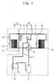
- Figure 1 is a schematic view of an air conditioner according to a first embodiment of the present invention;
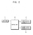
- Figure 2 is a control block diagram of the air conditioner according to the first embodiment of the present invention;
- Figure 3 is a control flow chart of the air conditioner according to the first embodiment of the present invention;
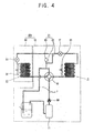
- Figure 4 is a schematic view of an air conditioner according to a second embodiment of the present invention; and
- Figure 5 is a schematic view of an air conditioner according to a third embodiment of the present invention.
- Referring to the drawings, there is shown in Figures 1 and 2 a first embodiment of an air conditioner comprising an
air conditioning system 1 provided to control air temperature and acontrol unit 40 to control theair conditioning system 1. - The
air conditioning system 1 comprises acompressor 11,heat exchangers compressor 11 and surrounding air,electric expansion valves heat exchangers accumulator 19 provided between theheat exchangers compressor 11. Arefrigerant tube 7 forms a closed circuit such that the refrigerant circulates through thecompressor 11, theheat exchangers accumulator 19. Theair conditioning system 1 further comprises apressure control unit 21 provided to control the pressure of the refrigerant in the portion of refrigerant tube located between theelectric expansion valves way valve 13 is provided to change the refrigerant flow direction through theheat exchangers heat exchanger air conditioning system 1 comprises oneindoor unit 30 provided in a building such as a house or an office and a factory to cool or heat the interior air and anoutdoor unit 10 connected to theindoor unit 30. However, theair conditioning system 1 may be provided as a single body equipped in one casing. In this embodiment, the air conditioning system further comprises areceiver 27 provided between the plurality ofelectric expansion valves - The
heat exchangers first heat exchanger 15 provided in theoutdoor unit 10, and asecond heat exchanger 31 provided in theindoor unit 30. Eachheat exchanger ventilation fan 35 adjacent thereto to accelerate the heat exchange across the heat exchanger by forced convection. - When the
air conditioning system 1 performs a cooling operation, thefirst heat exchanger 15 operates as a condenser to condense the refrigerant compressed from thecompressor 11 and thesecond heat exchanger 31 operates as an evaporator to evaporate the refrigerant by absorbing heat from the surrounding air. When theair conditioning system 1 performs a heating operation, thefirst heat exchanger 15 operates as an evaporator to evaporate the refrigerant and thefirst heat exchanger 15 operates as a condenser to condense the refrigerant compressed from the compressor. - The
second heat exchanger 31 may be provided as a plurality of heat exchangers according to the quantity ofindoor units 30. - The
electric expansion valves electric expansion valve 17 provided in theoutdoor unit 10 and a secondelectric expansion valve 33 provided in theindoor unit 30. - The
electric expansion valves refrigerant pipe 7 located between thefirst heat exchanger 15 and thesecond heat exchanger 31, the firstelectric expansion valve 17 being located proximate to thefirst heat exchanger 15 and the secondelectric expansion valve 33 being located proximate to thesecond heat exchanger 31. - When the
air conditioning system 1 performs a cooling operation, the firstelectric expansion valve 17 opens completely such that the refrigerant passing therethrough does not expand and the secondelectric expansion valve 33 is controlled such that high temperature and high pressure refrigerant passing therethrough expands to a low temperature and low pressure refrigerant. - When the
air conditioning system 1 performs a heating operation, the firstelectric expansion valve 33 is controlled such that high temperature and high pressure refrigerant passing therethrough expands to low temperature and low pressure refrigerant and the secondelectric expansion valve 33 opens completely such that the refrigerant passing therethrough does not expand. - The
accumulator 19 accommodates the refrigerant transmitted from theheat exchangers compressor 11. It may also be provided to prevent the supply of liquid refrigerant to thecompressor 11. Theaccumulator 19 is located lower than the first and thesecond heat exchangers refrigerant pipe 7 flows into theaccumulator 19 due to gravity when theair conditioning system 1 stops operating. When this occurs, the firstelectronic expansion valve 17 and the secondelectronic expansion valve 33 are closed by thecontrol unit 40 such that the refrigerant located between the firstelectronic expansion valve 17 and the secondelectronic expansion valve 33 does not flow to theaccumulator 19 and so the size of theaccumulator 19 may be reduced. - The four-
way valve 13 controls the flow direction of the refrigerant in the air conditioning system to alternately select the cooling or heating operation. When theair conditioning system 1 performs a cooling operation, the refrigerant compressed by thecompressor 11 is supplied to thefirst heat exchanger 15 by the four-way valve 15 and the refrigerant from thesecond heat exchanger 31 is supplied to theaccumulator 19. When theair conditioning system 1 performs a heating operation, the refrigerant compressed by thecompressor 11 is supplied by the four-way valve to thesecond heat exchanger 31 and the refrigerant from thefirst heat exchanger 15 is supplied to theaccumulator 19. - The
pressure control unit 21 is provided as a means to prevent the pressure of the refrigerant located between theelectric expansion valves electric expansion valves control unit 40. This predetermined pressure is preferably but not necessarily lower than an endurable pressure of therefrigerant pipe 7 located between theelectric expansion valves pressure control unit 21 comprises anauxiliary pipe 23 connected with respect to therefrigerant pipe 7 between theelectric expansion valves accumulator 19, and arelief valve 25 provided to theauxiliary pipe 23. However, thepressure control unit 21 is not limited to theauxiliary pipe 23 and therelief valve 25. - The
auxiliary pipe 23 connects therefrigerant pipe 7 provided between the first and the secondelectric expansion valves refrigerant pipe 7 provided between the four-way valve 13 and theaccumulator 19. Alternatively, theauxiliary pipe 23 may be located to connect therefrigerant pipe 7 provided between the first and the secondelectric expansion valves refrigerant pipe 7 provided between the secondelectric expansion valve 33 and thesecond heat exchanger 31. - The
relief valve 25 opens when the pressure of the refrigerant in the section ofrefrigerant pipe 7 between the first and the secondelectric expansion valves accumulator 19. - The
receiver 27 is located between the first and the secondelectric expansion valves electric expansion valve air conditioning system 1 operates in a stable manner. - The
compressor 11, thefirst heat exchanger 15, theaccumulator 19 and the firstelectric expansion valve 17 are located in the outdoor unit. As shown in Figure 1, the four-way valve 13, thepressure control unit 21 and thereceiver 27 may also be located in the outdoor unit as well as theventilation fan 35 adjacent to thefirst heat exchanger 15. - The
second heat exchanger 31 and the secondelectric expansion valve 33 are located in the indoor unit as well as theventilation fan 35 adjacent to thesecond heat exchanger 31. - The
control unit 40 controls the first and secondelectric expansion valves electric expansion valves accumulator 19 when theair conditioning system 1 stops operating. Thecontrol unit 40 opens the first and secondelectric expansion valves electric expansion valve 17 or the secondelectric expansion valve 33 may perform an expansion function when theair conditioning system 1 is operating. - With the above configuration, the control process of the air conditioner according to the first embodiment of the present invention is described hereafter with reference to the control flowchart of Figure 3.
- First of all, power is applied to the
air conditioning system 1 at operation S1. Thecompressor 11 then operates and the refrigerant circulates through therefrigerant pipe 7 at operation S3. Subsequently, the central process confirms whether thecompressor 11 is operating at operation S5. This may occur on a periodical basis or a signal stopping the operation of thecompressor 11 may be sensed. If the compressor stops operating the first andsecond expansion valves electric expansion valve 17 and the secondelectric expansion valve 33 cannot flow to theaccumulator 19. - As described above, the air conditioner according to the first embodiment of the invention closes the
electric expansion valves - Figure 4 is a schematic view of an air conditioner according to a second embodiment of the present invention. As shown therein, an
air conditioning system 101 differs from the first embodiment in that theair conditioning system 101 further comprises acheck valve 50 provided at the outlet of thecompressor 11 to prevent the refrigerant flowing backwards to thecompressor 11. - As shown in Figure 4 the
check valve 50 is provided between thecompressor 11 and the four-way valve 13 and prevents the backward flow of refrigerant from thefirst heat exchanger 15 or thesecond heat exchanger 31 to thecompressor 11. - In this embodiment wherein the
check valve 50 is provided, thecontrol unit 40 closes one of either the first or secondelectric expansion valves compressor 11 is stopped. Thecontrol unit 40 closes the secondelectric expansion valve 33 when the operation of thecompressor 11 is stopped during the cooling operation and closes the firstelectric expansion valve 17 when the operation of thecompressor 11 is stopped during the heating operation. - Thus, the air conditioner according to the second embodiment of the present invention may close the electric expansion valves when the compressor stops operating and prevent the refrigerant interposed between one of the electric expansion valves and the check valve as well as that interposed between the electric expansion valves from flowing to the accumulator thereby reducing the size of the accumulator.
- Figure 5 is a schematic view of an air conditioner according to a third embodiment of the present invention. As shown therein, the air conditioner according to the third embodiment comprises an
air conditioning system 201 provided to control air temperature and a control unit (not shown) controlling theair conditioning system 201. - The
air conditioning system 201 comprises thecompressor 11,heat exchangers compressor 11, anelectric expansion valve 217 provided between theheat exchangers accumulator 19 provided between theheat exchangers compressor 11, and thecheck valve 50 provided at a refrigerant outlet of thecompressor 11 to prevent the refrigerant from flowing backwards to the compressor. Theair conditioning unit 201 may further comprise the four-way valve 13 provided to change the refrigerant flow direction through theheat exchangers - The
electric expansion valve 217 is provided as a single unit different from the foregoing first and second embodiments. The detailed explanation about the function of theelectric expansion valve 217 will be avoided because it is similar to the first embodiment. - During a cooling operation, the
first heat exchanger 15 functions as the condenser to condense the refrigerant from thecompressor 11 and thesecond heat exchanger 31 functions as the evaporator to evaporate and to absorb heat from surrounding air. - During a heating operation, the
first heat exchanger 15 functions as the evaporator to evaporate and to absorb heat from surrounding air and thesecond heat exchanger 31 functions as the condenser to condense the refrigerant compressed from thecompressor 11. - The explanation about the four-
way valve 13 will be omitted because it is similar to the foregoing first embodiment. - The control unit (not shown) controls the
electric expansion valve 217 such that the refrigerant located between theelectric expansion valve 217 and thecheck valve 50 does not flow to theaccumulator 19 when it is closed. - Thus, the air conditioner according to the third embodiment of the present invention may prevent the refrigerant located between the
electric expansion valve 217 and thecheck valve 50 from flowing to theaccumulator 19 if the control unit closes the electric expansion valve when the operation of the compressor stops. Accordingly, the size of theaccumulator 19 may be reduced. - Further features shown in Figure 5 are omitted from the description as they are similar to the first and second embodiments.
- Although embodiments of the present invention have been shown and described, it will be appreciated by those skilled in the art that changes may be made in these embodiments without departing from the principles of the invention, the scope of which is defined in the claims and their equivalents and the foregoing description should be regarded as a description of preferred embodiments only.
Claims (15)
- An air conditioner comprising a compressor, a plurality of heat exchangers, an accumulator and, at least one expansion valve connected in a refrigeration circuit operable to perform a cooling and/or heating cycle and, a control unit for controlling operation of the air conditioner characterised in that when the compressor stops, the control unit is configured so as to close at least one expansion valve to prevent refrigerant from flowing into the accumulator.
- An air conditioner according to claim 1 wherein an expansion valve is located in the refrigeration circuit between each heat exchanger and the accumulator.
- An air conditioner according to claim 1 comprising a single expansion valve in the refrigeration circuit between each pair of heat exchangers.
- An air conditioner according to any preceding claim wherein a refrigerant flow check valve is located in the refrigeration circuit to prevent back flow of refrigerant into the compressor when the compressor is stopped.
- An air conditioner according to any of claims 1, 2 and 4 wherein a pressure control valve is disposed between expansion valves, the control unit being configured to open the pressure control valve when the pressure of refrigerant in the refrigeration circuit between said expansion valves exceeds a predetermined pressure.
- A method of controlling an air conditioner comprising a compressor, a plurality of heat exchangers, an accumulator and, at least one expansion valve connected in a refrigeration circuit operable to perform a cooling and/or heating cycle and, a control unit for controlling operation of the air conditioner characterised by the step of closing at least one expansion valve when the compressor stops, to prevent refrigerant from flowing into the accumulator.
- An air conditioner comprising a freezing device comprising a compressor, a plurality of heat exchangers to heat exchange a refrigerant supplied from the compressor, a plurality of electric expansion valves provided between the plurality of the heat exchangers and an accumulator provided between the heat exchanger and the compressor and a control unit controlling to close the plurality of the electric expansion valves to prevent the refrigerant located between the plurality of electric expansion valves from being accommodated in the accumulator when the operation of the compressor stops.
- The air conditioner according to claim 7 wherein the freezing device further comprises a check valve provided in a refrigerant exit area of the compressor and preventing the refrigerant to flow backward to the compressors.
- The air conditioner according to claims 7 or 8 wherein the freezing device further comprises a pressure control unit provided to control the pressure of the refrigerant accommodated between the plurality of the electric expansion valves.
- The air conditioner according to claim 9 wherein the pressure control unit comprises a refrigerant pipe provided between the plurality of the electric expansion valves, an auxiliary pipe connected to the accumulator and a relief valve provided in the auxiliary pipe.
- The air conditioner according to claim 7 wherein the freezing device further comprises a four way valve provided to change the refrigerant flow direction in the plurality of the heat exchangers to make an air cooling and an air heating operation possible.
- The air conditioner according to claim 7 wherein the freezing device further comprises a receiver provided between the plurality of the electric expansion valves and accommodating the refrigerant and provided to discharge a liquid refrigerant.
- The air conditioner according to claim 7 or claim 12 wherein the freezing device further comprises an outdoor unit comprising the compressor, one of the plurality of the heat exchangers and the accumulator and an indoor unit comprising at least another one of the plurality of the heat exchangers, one of the plurality of the electric expansion valve is equipped to the indoor unit and at least another one of the plurality of the electric expansion valves is equipped to the indoor unit.
- An air conditioner comprising a freezing device comprising a compressor and a plurality of heat exchangers to heat exchange a refrigerant supplied from the compressor, an electric expansion valve provided between the plurality of the heat exchangers, an accumulator provided between the heat exchanger and the compressor, and a check valve provided in a refrigerant exit area of the compressor and preventing the refrigerant from flowing backward to the compressor, a control unit controlling to close the electric expansion valve to prevent the refrigerant located between the electric expansion valve and the check valve from being accommodated in the accumulator when the operation of the compressor stops.
- The air conditioner according to claim 14 wherein the freezing device further comprises a four way valve provided to change the refrigerant flow direction in the plurality of the heat exchangers to make an air cooling and an air heating operation possible.
Applications Claiming Priority (1)
| Application Number | Priority Date | Filing Date | Title |
|---|---|---|---|
| KR1020040110336A KR100671301B1 (en) | 2004-12-22 | 2004-12-22 | Air conditioner |
Publications (2)
| Publication Number | Publication Date |
|---|---|
| EP1674807A2 true EP1674807A2 (en) | 2006-06-28 |
| EP1674807A3 EP1674807A3 (en) | 2007-07-04 |
Family
ID=36177368
Family Applications (1)
| Application Number | Title | Priority Date | Filing Date |
|---|---|---|---|
| EP05104573A Withdrawn EP1674807A3 (en) | 2004-12-22 | 2005-05-27 | Air conditioner |
Country Status (3)
| Country | Link |
|---|---|
| EP (1) | EP1674807A3 (en) |
| KR (1) | KR100671301B1 (en) |
| CN (1) | CN1793758A (en) |
Cited By (4)
| Publication number | Priority date | Publication date | Assignee | Title |
|---|---|---|---|---|
| EP2320151A4 (en) * | 2008-07-29 | 2011-09-07 | Daikin Ind Ltd | AIR CONDITIONING |
| DE102015114309A1 (en) * | 2015-08-28 | 2017-03-02 | Halla Visteon Climate Control Corporation | Bidirectional electronic expansion organ |
| WO2018177476A1 (en) * | 2017-04-01 | 2018-10-04 | Viessmann Werke Gmbh & Co Kg | Heat pump |
| US20220252313A1 (en) * | 2019-08-07 | 2022-08-11 | Mitsubishi Electric Corporation | Chilling unit |
Families Citing this family (2)
| Publication number | Priority date | Publication date | Assignee | Title |
|---|---|---|---|---|
| KR20100062115A (en) * | 2008-12-01 | 2010-06-10 | 삼성전자주식회사 | Air conditioner and control method thereof |
| KR102146371B1 (en) | 2013-09-25 | 2020-08-20 | 삼성전자주식회사 | Air Conditioner |
Family Cites Families (11)
| Publication number | Priority date | Publication date | Assignee | Title |
|---|---|---|---|---|
| GB1595616A (en) * | 1977-01-21 | 1981-08-12 | Hitachi Ltd | Air conditioning system |
| US4735054A (en) * | 1987-08-13 | 1988-04-05 | Honeywell Inc. | Method for minimizing off cycle losses of a refrigeration system during a cooling mode of operation and an apparatus using the method |
| JP3322684B2 (en) * | 1992-03-16 | 2002-09-09 | 東芝キヤリア株式会社 | Air conditioner |
| JPH102623A (en) | 1996-06-11 | 1998-01-06 | Mitsubishi Heavy Ind Ltd | Refrigerator |
| JPH1114177A (en) | 1997-06-26 | 1999-01-22 | Mitsubishi Heavy Ind Ltd | Air conditioner |
| JP3109500B2 (en) * | 1998-12-16 | 2000-11-13 | ダイキン工業株式会社 | Refrigeration equipment |
| KR20010048760A (en) * | 1999-11-29 | 2001-06-15 | 윤종용 | Operating control method of air conditioner |
| US6385980B1 (en) * | 2000-11-15 | 2002-05-14 | Carrier Corporation | High pressure regulation in economized vapor compression cycles |
| US6672090B1 (en) * | 2002-07-15 | 2004-01-06 | Copeland Corporation | Refrigeration control |
| JP4156353B2 (en) * | 2002-12-02 | 2008-09-24 | 株式会社テージーケー | Refrigeration system and operation method thereof |
| KR100564444B1 (en) * | 2003-10-20 | 2006-03-29 | 엘지전자 주식회사 | Apparatus and method for preventing accumulation of liquid refrigerant in air conditioners |
-
2004
- 2004-12-22 KR KR1020040110336A patent/KR100671301B1/en not_active Expired - Fee Related
-
2005
- 2005-05-17 CN CNA2005100726404A patent/CN1793758A/en active Pending
- 2005-05-27 EP EP05104573A patent/EP1674807A3/en not_active Withdrawn
Cited By (7)
| Publication number | Priority date | Publication date | Assignee | Title |
|---|---|---|---|---|
| EP2320151A4 (en) * | 2008-07-29 | 2011-09-07 | Daikin Ind Ltd | AIR CONDITIONING |
| DE102015114309A1 (en) * | 2015-08-28 | 2017-03-02 | Halla Visteon Climate Control Corporation | Bidirectional electronic expansion organ |
| DE102015114309B4 (en) * | 2015-08-28 | 2020-01-30 | Hanon Systems | Bi-directional electronic expansion device |
| WO2018177476A1 (en) * | 2017-04-01 | 2018-10-04 | Viessmann Werke Gmbh & Co Kg | Heat pump |
| US20220252313A1 (en) * | 2019-08-07 | 2022-08-11 | Mitsubishi Electric Corporation | Chilling unit |
| EP4012289A4 (en) * | 2019-08-07 | 2022-09-28 | Mitsubishi Electric Corporation | COOLING UNIT |
| US12038210B2 (en) * | 2019-08-07 | 2024-07-16 | Mitsubishi Electric Corporation | Chilling unit |
Also Published As
| Publication number | Publication date |
|---|---|
| EP1674807A3 (en) | 2007-07-04 |
| KR20060071659A (en) | 2006-06-27 |
| KR100671301B1 (en) | 2007-01-19 |
| CN1793758A (en) | 2006-06-28 |
Similar Documents
| Publication | Publication Date | Title |
|---|---|---|
| US20210348820A1 (en) | Heat load processing system | |
| CN101802512B (en) | Methods and systems for controlling integrated air conditioning systems | |
| KR20130031090A (en) | Air conditioner and controlling method of the same | |
| JP2012141113A (en) | Air conditioning/water heating device system | |
| US6711909B2 (en) | Outdoor fan control system of air conditioner and control method thereof | |
| US20040107709A1 (en) | Method for operating compressors of air conditioner | |
| KR101702178B1 (en) | Chiller system | |
| US7578137B2 (en) | Air-conditioning system with multiple indoor and outdoor units and control system therefor | |
| US8667810B2 (en) | Air conditioning system for communication equipment | |
| KR101029988B1 (en) | Automatic control of blower air volume according to the change of refrigerant flow rate in the direct expansion type air conditioner | |
| US7380407B2 (en) | Multi air conditioning system and method for operating the same | |
| EP1674807A2 (en) | Air conditioner | |
| KR101073501B1 (en) | A air conditioner for multi-step driving | |
| KR102104818B1 (en) | chiller | |
| KR100423362B1 (en) | Air conditioner | |
| CN115279603A (en) | Vehicle air conditioner and control method thereof | |
| EP1686332A2 (en) | Reversible cycle air conditioner | |
| KR100408994B1 (en) | Cooling drive indoor fan control method for multitype airconditioner | |
| KR101116209B1 (en) | An air conditioner for multi-step driving | |
| KR100535687B1 (en) | A Multi-type Air Conditioner | |
| JP4420393B2 (en) | Refrigeration air conditioner | |
| CN213362683U (en) | Air conditioner | |
| CN118019948A (en) | air conditioner | |
| JP2002174470A (en) | Freezer | |
| KR20020038171A (en) | Multi Airconditioner used Solenoid Valve and Check Valve |
Legal Events
| Date | Code | Title | Description |
|---|---|---|---|
| PUAI | Public reference made under article 153(3) epc to a published international application that has entered the european phase |
Free format text: ORIGINAL CODE: 0009012 |
|
| AK | Designated contracting states |
Kind code of ref document: A2 Designated state(s): AT BE BG CH CY CZ DE DK EE ES FI FR GB GR HU IE IS IT LI LT LU MC NL PL PT RO SE SI SK TR |
|
| AX | Request for extension of the european patent |
Extension state: AL BA HR LV MK YU |
|
| PUAL | Search report despatched |
Free format text: ORIGINAL CODE: 0009013 |
|
| AK | Designated contracting states |
Kind code of ref document: A3 Designated state(s): AT BE BG CH CY CZ DE DK EE ES FI FR GB GR HU IE IS IT LI LT LU MC NL PL PT RO SE SI SK TR |
|
| AX | Request for extension of the european patent |
Extension state: AL BA HR LV MK YU |
|
| 17P | Request for examination filed |
Effective date: 20071026 |
|
| AKX | Designation fees paid |
Designated state(s): DE FR GB |
|
| 17Q | First examination report despatched |
Effective date: 20090817 |
|
| STAA | Information on the status of an ep patent application or granted ep patent |
Free format text: STATUS: THE APPLICATION IS DEEMED TO BE WITHDRAWN |
|
| 18D | Application deemed to be withdrawn |
Effective date: 20091201 |