EP1679457B1 - Joint plat - Google Patents
Joint plat Download PDFInfo
- Publication number
- EP1679457B1 EP1679457B1 EP06008918A EP06008918A EP1679457B1 EP 1679457 B1 EP1679457 B1 EP 1679457B1 EP 06008918 A EP06008918 A EP 06008918A EP 06008918 A EP06008918 A EP 06008918A EP 1679457 B1 EP1679457 B1 EP 1679457B1
- Authority
- EP
- European Patent Office
- Prior art keywords
- profile
- flat gasket
- wave
- layer
- gasket according
- Prior art date
- Legal status (The legal status is an assumption and is not a legal conclusion. Google has not performed a legal analysis and makes no representation as to the accuracy of the status listed.)
- Expired - Lifetime
Links
- 239000002184 metal Substances 0.000 claims abstract description 19
- 239000011324 bead Substances 0.000 claims description 41
- 239000000463 material Substances 0.000 claims description 13
- 239000000945 filler Substances 0.000 claims description 4
- 229910000639 Spring steel Inorganic materials 0.000 claims description 3
- 229910000831 Steel Inorganic materials 0.000 claims description 3
- 239000010959 steel Substances 0.000 claims description 3
- 238000005496 tempering Methods 0.000 claims description 2
- 230000007704 transition Effects 0.000 claims description 2
- 238000000034 method Methods 0.000 abstract description 2
- 239000010410 layer Substances 0.000 description 95
- 230000002093 peripheral effect Effects 0.000 description 9
- 238000007789 sealing Methods 0.000 description 9
- 239000011248 coating agent Substances 0.000 description 4
- 238000000576 coating method Methods 0.000 description 4
- 230000006835 compression Effects 0.000 description 4
- 238000007906 compression Methods 0.000 description 4
- 230000000694 effects Effects 0.000 description 4
- 229920001971 elastomer Polymers 0.000 description 4
- 239000000806 elastomer Substances 0.000 description 4
- 238000004519 manufacturing process Methods 0.000 description 4
- 238000003825 pressing Methods 0.000 description 4
- 230000003014 reinforcing effect Effects 0.000 description 4
- 239000002356 single layer Substances 0.000 description 4
- 230000008901 benefit Effects 0.000 description 3
- 230000015572 biosynthetic process Effects 0.000 description 3
- 230000008859 change Effects 0.000 description 3
- 230000006978 adaptation Effects 0.000 description 2
- 238000005452 bending Methods 0.000 description 2
- 238000009933 burial Methods 0.000 description 2
- 238000002485 combustion reaction Methods 0.000 description 2
- 238000004049 embossing Methods 0.000 description 2
- 238000009434 installation Methods 0.000 description 2
- 239000000126 substance Substances 0.000 description 2
- 230000008719 thickening Effects 0.000 description 2
- 238000013016 damping Methods 0.000 description 1
- 230000001419 dependent effect Effects 0.000 description 1
- 230000006872 improvement Effects 0.000 description 1
- 230000003993 interaction Effects 0.000 description 1
- 239000007769 metal material Substances 0.000 description 1
- 238000000465 moulding Methods 0.000 description 1
- 230000002787 reinforcement Effects 0.000 description 1
- 238000007493 shaping process Methods 0.000 description 1
- 238000003466 welding Methods 0.000 description 1
Images


Classifications
-
- F—MECHANICAL ENGINEERING; LIGHTING; HEATING; WEAPONS; BLASTING
- F16—ENGINEERING ELEMENTS AND UNITS; GENERAL MEASURES FOR PRODUCING AND MAINTAINING EFFECTIVE FUNCTIONING OF MACHINES OR INSTALLATIONS; THERMAL INSULATION IN GENERAL
- F16J—PISTONS; CYLINDERS; SEALINGS
- F16J15/00—Sealings
- F16J15/02—Sealings between relatively-stationary surfaces
- F16J15/06—Sealings between relatively-stationary surfaces with solid packing compressed between sealing surfaces
- F16J15/08—Sealings between relatively-stationary surfaces with solid packing compressed between sealing surfaces with exclusively metal packing
- F16J15/0818—Flat gaskets
- F16J15/0825—Flat gaskets laminated
-
- F—MECHANICAL ENGINEERING; LIGHTING; HEATING; WEAPONS; BLASTING
- F16—ENGINEERING ELEMENTS AND UNITS; GENERAL MEASURES FOR PRODUCING AND MAINTAINING EFFECTIVE FUNCTIONING OF MACHINES OR INSTALLATIONS; THERMAL INSULATION IN GENERAL
- F16J—PISTONS; CYLINDERS; SEALINGS
- F16J15/00—Sealings
- F16J15/02—Sealings between relatively-stationary surfaces
- F16J15/06—Sealings between relatively-stationary surfaces with solid packing compressed between sealing surfaces
- F16J15/08—Sealings between relatively-stationary surfaces with solid packing compressed between sealing surfaces with exclusively metal packing
- F16J15/0818—Flat gaskets
- F16J2015/0837—Flat gaskets with an edge portion folded over a second plate or shim
-
- F—MECHANICAL ENGINEERING; LIGHTING; HEATING; WEAPONS; BLASTING
- F16—ENGINEERING ELEMENTS AND UNITS; GENERAL MEASURES FOR PRODUCING AND MAINTAINING EFFECTIVE FUNCTIONING OF MACHINES OR INSTALLATIONS; THERMAL INSULATION IN GENERAL
- F16J—PISTONS; CYLINDERS; SEALINGS
- F16J15/00—Sealings
- F16J15/02—Sealings between relatively-stationary surfaces
- F16J15/06—Sealings between relatively-stationary surfaces with solid packing compressed between sealing surfaces
- F16J15/08—Sealings between relatively-stationary surfaces with solid packing compressed between sealing surfaces with exclusively metal packing
- F16J15/0818—Flat gaskets
- F16J2015/085—Flat gaskets without fold over
-
- F—MECHANICAL ENGINEERING; LIGHTING; HEATING; WEAPONS; BLASTING
- F16—ENGINEERING ELEMENTS AND UNITS; GENERAL MEASURES FOR PRODUCING AND MAINTAINING EFFECTIVE FUNCTIONING OF MACHINES OR INSTALLATIONS; THERMAL INSULATION IN GENERAL
- F16J—PISTONS; CYLINDERS; SEALINGS
- F16J15/00—Sealings
- F16J15/02—Sealings between relatively-stationary surfaces
- F16J15/06—Sealings between relatively-stationary surfaces with solid packing compressed between sealing surfaces
- F16J15/08—Sealings between relatively-stationary surfaces with solid packing compressed between sealing surfaces with exclusively metal packing
- F16J15/0818—Flat gaskets
- F16J2015/0862—Flat gaskets with a bore ring
-
- F—MECHANICAL ENGINEERING; LIGHTING; HEATING; WEAPONS; BLASTING
- F16—ENGINEERING ELEMENTS AND UNITS; GENERAL MEASURES FOR PRODUCING AND MAINTAINING EFFECTIVE FUNCTIONING OF MACHINES OR INSTALLATIONS; THERMAL INSULATION IN GENERAL
- F16J—PISTONS; CYLINDERS; SEALINGS
- F16J15/00—Sealings
- F16J15/02—Sealings between relatively-stationary surfaces
- F16J15/06—Sealings between relatively-stationary surfaces with solid packing compressed between sealing surfaces
- F16J15/08—Sealings between relatively-stationary surfaces with solid packing compressed between sealing surfaces with exclusively metal packing
- F16J15/0818—Flat gaskets
- F16J2015/0875—Flat gaskets comprising welds
Definitions
- the invention relates to a flat gasket, in each of which at least one passage opening is formed.
- the multilayer flat gasket can be designed and used in particular as a cylinder head gasket, but also for other surfaces to be sealed together, such as a wide variety of flange gaskets.
- Such a bead can fulfill the function only as long as a certain degree of elasticity is maintained in the bead area, which can usually not be met without additional aids, with which a complete plastic deformation is prevented.
- deformation limiters are usually used for the beads. Such deformation limiters are known in various embodiments and are commonly referred to as "stoppers". Thus, deformation limiters can be obtained by bending one of the metallic layers or additional elements.
- the grooves can not be introduced arbitrarily deep and reproducible with any density in the metallic layer.
- the JP 7-41137 U discloses a two-layered cylinder head gasket, which has in one of its layers a circumferential bead surrounding the combustion chamber. In a position adjacent thereto, a deformation limiter is provided for this bead.
- the deformation limiter has a coating which leads to an elevation of the layer. In addition, this coating is embedded in a wave-shaped profiling which prevents the detachment and the loss of the coating.
- the flat gasket according to the invention which consists of a plurality of superimposed metallic layers
- known grooving in at least one of the metallic layers profiling at least partially around the one or more through holes, especially at through holes for combustion chambers in cylinder head gaskets used In this case, such profiling can be formed in waveform by this form is impressed into the respective metallic layer.
- shaft in the present invention also includes embodiments that deviate from a sinusoidal shaft.
- the wave can therefore be flattened in the mountains and valleys and z. B. have straight flanks.
- the term wave of the present invention also includes trapezoidal configurations.
- the wave according to the invention in this case has a period length ⁇ 1.5.
- the profiling is at least partially around the passage opening (s) around, as far as possible adapted to the outer contour formed.
- Such a profiling has three or more peaks or three or more teeth on each side of the seal. In this case, a good sealing behavior is achieved even without filling or coating of the profiling.
- the respective wave crests or troughs can also be flattened or flattened, whereby a particularly effective bearing surface of the stopper is formed on the adjacent gasket layers.
- the heights of the wave crests, i. the amplitude not necessarily constant over the entire profiling, but may be different in size in certain peripheral areas around a passage opening, taking into account the respective geometric shape. In the same way, the distances between wave crests can be varied.
- different amplitudes of the wave crests and / or different distances between the individual crests and different radii of the waves, starting with increasing distance from the edge of the respective passage opening can be adjusted to specifically influence the elasticity and the spring stiffness locally.
- a plastic deformation of a region of such a profiling can also be defined or already made prior to the installation of such a flat gasket.
- the transition region between wave troughs and wave crests may have a smaller material thickness than the wave crests / valleys.
- the material thickness can be profiled and the properties of the profiling adapted to the specific conditions. It is also possible not to compress the flanks, but the mountains or valleys. A so-called radius compression then leads to a thickening of the flanks.
- the profiling is used as a deformation limiter for additionally formed beads.
- the profiling is formed in a multi-layer seal in one layer and the bead in an adjacent layer.
- a flat gasket may also consist of at least two metal layers, both of which have a corrugated profiling. These profiles can come to lie one above the other.
- the profiles in the two layers are designed differently with respect to the length, the depth and / or the radius of the respective shaft (amplitude, profile height and radius). If such two differently designed shaft beads are brought directly into contact with each other in the motor in compression, the relative movement of each of the shaft beads is dependent on the respective shaft structure.
- the difference of the relative movement of the two profiles can be used for sealing as an elastic spring element with a high clamping force.
- the full bead can be saved in one of the sheets and yet the clamping force of a full bead are exceeded.
- the layer which has the profiling can, in the region of the profiling, be replaced by at least one further layer, e.g. a ring, advantageously be reinforced with the width of the profiling.
- This layer or this ring can surround the profiled layer along the peripheral edge of the passage opening at least partially and form a so-called rebate stopper there.
- the reinforcing layer or the reinforcing ring can have the same profiling, and consequently both profilings can lie in a form-fitting manner against one another.
- the amplitude, period and radius of the profiling of the reinforcing layer or the reinforcing ring along the peripheral edge and / or perpendicular to the peripheral edge of the passage opening can be varied. If period, amplitude and radius differ from one another on adjacent layers, the sealing behavior can be further influenced in this way.
- the stopper (layer or ring) can be connected to the shaft stopper using freely selectable welding methods. Through this welded stopper a variable overhang is achieved, which also contains an elastic portion. The choice of thickness the additional stopper makes it possible to match the seal in the stopper area to the engine conditions. So very high and robust designs can be achieved, for example, for diesel engines in the truck sector.
- the profiling of one or more layers can also be almost optimized by appropriate design and dimensioning by the elasticity, the spring stiffness and a targeted desired level of plastic deformation in the different areas of such profiling can be adjusted.
- the region of a profiling which points in the direction of a passage opening can also have smaller distances between the wave crests from one another than the regions further away. Accordingly, in the former region, the elasticity is smaller than in the compacted regions of such profiling.
- the distances and / or heights can also be successively increased, starting from the outer edge of a passage opening.
- the densified areas of a profiling have a lower elasticity and in contrast are limited plastically deformable and this area can accordingly possibly take over the function of a deformation limiter.
- a variation of the number of wave peaks or valleys, the sheet thickness, the heights or shape, in particular the radii of the peaks / valleys and their distance and the like can be done.
- the metal layers in which the profiling is incorporated may also be in relation to their top and bottom, i. the two sides, which in the installed state, for example, facing the cylinder head or the cylinder block, are designed differently, e.g. with respect to the height and shape of the wave peaks / valleys and the like, so that the stopper can cope with the different properties of, for example, cylinder head and cylinder block, which may be made of different materials.
- the layer which has the profiling can furthermore be formed from cold-workable steel, for example a martensite-hardening steel such as Zapp VACL 180T, which cures by tempering, for example to 300 ° C.
- cold-workable steel for example a martensite-hardening steel such as Zapp VACL 180T, which cures by tempering, for example to 300 ° C.
- the stiffness of certain areas of a profiling can also be increased by means of webs which are arranged and formed between the individual adjacent crests. Such webs can be used in a series, but also in a staggered arrangement. However, the webs can also be present only in a region which is arranged at a greater distance from the respective passage opening.
- the profiling to be used according to the invention can be formed in a wide variety of metallic materials, that is to say also in different spring steel materials, with spring steel achieving even greater elasticity and consequently an improvement in the sealing effect over a long period of time.
- the flat gasket according to the invention can additionally be developed by applying substances known per se to at least one side of a metallic layer.
- Suitable substances for example elastomers, are for example in DE 198 29 058 .
- Such a filler is then present at least in areas and parts of the profiling and the elasticity and spring stiffness can be influenced by means of the respective elastomer.
- Another influencing factor when using such fillers is in addition to their arrangement, the respective degree of filling in the profiling. This means that the troughs of such profiling can be completely, but also partially filled, so that in addition to the already mentioned local influence on elasticity and spring stiffness and the damping properties can be influenced in different ways.
- the degree of filling can be changed with increasing distance from the edge of the through holes. But it can also be varied over the circumference of the respective passage openings.
- gaskets according to the invention regardless of whether they are to be produced with or without additional filler, can be produced with only a few technologically, easily manageable working steps and, consequently, particularly cost-effectively.
- properties can be set locally targeted.
- FIG. 1 shows an example of a single-layer gasket.
- This single-ply example is not an embodiment of the present invention, but is intended to illustrate certain aspects of the present invention, such as placing a bead and corrugation in one ply of a multi-ply gasket.
- a single-layer gasket is formed in the metallic layer 1, a bead 3 and toward a through hole, not shown here follows a wave-shaped profiling 2, the wave crests and troughs regularly arranged and consequently the crests a constant profile height and constant distances to each other exhibit.
- the profiling 2 in addition to the function of a deformation limiter for the bead 3, also fulfills a sealing function by the achievable elastic properties.
- the spring characteristic and consequently the elasticity by filling the gaps between the adjacent Wellenbergen profiling 2 be influenced with elastomer and with different degrees of filling.
- the spaces between the crests can be completely filled with an elastomer.
- a corresponding profiling 2 can also be formed on the other side of the bead 3.
- FIG. 2 shows an example of a three-layer gasket
- the flank taper can be taken schematically.
- beads 3 are again formed in the two outer layers 1 'of the flat gasket, and a similarly wave-shaped profiling 2 is correspondingly present in the middle layer 1.
- FIG. 1 shows the statements on possibilities of influencing properties already apply FIG. 1 have been made, also analogously to this example.
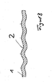
- FIG. 3 shows an example of a single-layer gasket.
- This single-ply example is not an embodiment of the present invention, but it is to illustrate individual aspects of the present invention, such as the provision of a wave-shaped profiling in a layer of a multi-layer seal, wherein in this situation has been dispensed with the formation of a bead is.
- the distances and profile heights of the individual peaks of the profiling 2 in a region near the edge, not shown here a passage opening smaller than is the case in the regions of the profiling 2 at a greater distance from the passage opening.
- the corresponding closer areas are stiffer and can be, if at all, only slightly plastically deformed.
- the profiling can be obtained in shape by using a correspondingly designed and dimensioned embossing tool already in the molding. However, it is possible to produce such a design of this area in a second technological step by appropriate upsetting and pressing.
- the previously obtained profiling 2 is subsequently completely or partially leveled, so that the profile height is reduced again in the leveled area.
- one or two punches with a flat parallel or at an angle inclined to the surface of the metallic layer 1 aligned pressing surfaces are pressed onto the area to be planned.
- the metallic layer 1, in particular at the edges of the profiling 2 should be braced.
- FIG. 4 shows another example of a flat gasket with a single metal layer 1, in which a bead 3 is embossed.
- this gasket consists of a single metal layer 1 and a ring 8, instead of at least two metallic layers.
- a wave-shaped stopper region 2 is arranged between the bead 3 and the right hand passage opening. This has a total of three wave peaks and three troughs.
- a ring 8 is welded along the peripheral edge of the passage opening, the same profiling as the metal layer 1 and bears against this form-fitting manner. In the ring 8 is therefore also a profiling 2 'formed with three wave crests and three troughs.
- the flat gasket according to the invention can be adapted to variable engine geometries or engine conditions, in which both the width and the material thickness of the metal ring 8 are selected accordingly.
- FIG. 5 shows sections of four further flat gaskets. According to the individual layers shown in each case are part of a multi-layer seal. In particular, all of these sectional drawings show profilings with a flank taper according to the characterizing feature of claim 1.
- FIGS. 5A and 5C have the same material thickness, while in the Figures 5B and 5D shown flat gaskets have a greater layer thickness.
- the waves in the stopper area 2 in the FIGS. 5A and 5B a smaller radius of curvature than in the flat gaskets in FIGS. 5C and 5D ,
- a large margin for adaptation possibilities of this stopper 2 to different engine characteristics are given.
- profiled areas 2 each have the material thickness in an intermediate region 6 between a wave crest 7 and an adjacent wave trough 7 less than in the region of wave troughs or wave crests 7. Also hereby, the elastic behavior of the stopper regions 2 can be varied.
- FIG. 6 shows a total of eight different variants gaskets.
- Figures 6E and 6F show examples of a flat gasket, which are not embodiments of the present invention, insofar as in Fig. 6E the wave-shaped profiles have no clear stopper function for a bead in an adjacent layer and Fig. 6F represents a single-layer seal. These examples, however, serve to explain individual aspects of the present invention and show examples of ways of arranging beading and profiling in a flat gasket.
- FIG. 6A shows a total of six-layer gasket of six metal layers 1a to 1f.
- Two profiled stopper areas 2b and 2e according to the invention are respectively formed in the layer 1b and the layer 1e and serve as deformation limiters for the beads 3a, 3c, 3d and 3f formed in the layers 1a, 1c, 1d and 1f.
- FIG. 6B a corresponding five-ply seal is shown, in turn, two layers are provided with profiled stopper areas.
- this Trap is inserted between the two upper layers 1a and 1b and the two lower layers 1d and 1e an intermediate layer 1c, which has neither a bead nor profiled.
- FIGS. 6C to 6E are three-layer flat gaskets shown, with in FIG. 6D the intermediate layer 1b has a step 4. Adjacent to the step 4 on one side is a profiled stopper region 2c, which acts as a stopper for the bead 3c. Characterized in that in the position 1b, an offset is provided, which faces away from the stopper region 2c, the elastic stopper function of the profiled region 2c is also used for the bead 3a in the position 1a via the position 1b offset in the profiled layer 1c.
- FIGS. 6F and 6G show two-layer flat gaskets in which a profiled region 2b is formed in each of the gasket layers. This serves as a stopper (deformation limiter) for the beads 3b in FIG. 6F or the beads 3a and 3b in FIG. 6G ,
- FIG. 6H again shows a four-layer gasket, wherein in the two outer layers 1a and 1d each facing a bead 3a and 3d is formed.
- These two outer layers 1a and 1d include two further layers 1b and 1c, which have no bead. However, they have laterally adjacent to the beads 3a and 3d selected areas 2b and 2c, which have the same profiling and form-fitting together.
- These two layers 1b and 1c form a stopper through the parallel profiled areas 2b and 2c in the profiled area (Deformation limiter) for the beads 3a and 3d.
- the sealing effect and the deformation limitation can be adapted to the particular conditions of the motor to be sealed.
- FIG. 7 shows examples of a gasket.
- examples 7A, 7C and 7D are not exemplary embodiments of the present invention, insofar as these examples have no wavy profiling in a position parallel to the first metallic layer in which the bead is arranged.
- Example 7B is not an embodiment of the invention insofar as the latter point is met, but the profiling 2a is folded over to 2c.
- Fig. 7A shows thereby a flat gasket
- the two metallic layers 1a, 1b has.
- the layer 1b is provided with a bead 3, to which a profiled region 2 adjoins immediately adjacent to the lead-through opening.
- the layer 1b adjacent layer 1a is not profiled, but surrounds the layer 1b along the peripheral edge of the passage opening and thus forms on the opposite position 1b a stopper ring 9 from. This results in the deformation-limiting stopper effect from the interaction of the profiling 2 with the stopper 9.
- Fig. 7B is a corresponding two-layer gasket as in Fig. 7A shown.
- the profiled area, here designated 2B, the layer 1b immediately adjacent areas of the layer 1A are provided in the same way with a profiling 2a and 2c, so that the position 1a is present on both sides of the profiled area 2B of the layer 1b positively.
- Fig. 7C shows an arrangement as in Fig. 7A
- the layer 1a is not provided as a full-surface metallic layer, but as a stopper ring 8 only in the profiling 2 of the metallic layer 1.
- the stopper 8 surrounds the layer 1 along the peripheral edge of the passage opening and forms a second stopper 9 from. It is therefore a folded stopper.
- Fig. 7D is in a similar way to Fig. 7C a folded stopper ring 8, 9 shown, but the profiling, here denoted by 2B, the position 1 immediately adjacent areas 2A and 2C of the stopper 8, 9 also in the same manner as the position 1 are profiled in the profiling area 2b and thus fit positively on both sides of the profiling 2b. Again, this is therefore a profiled folded stopper.
- both the amplitude and the distance of the individual peaks can be varied, either along the peripheral edge of the through hole or in the direction perpendicular to the peripheral edge of the through hole, but also the profiled regions 2A and 2C in the same Have a profiling with different amplitudes and wave intervals.
- wave crests between the individual layers may differ from one another at adjacent locations.
- the profiling 2a and 2c in the Figs. 7B and 7D have at each of the profiling 2b adjacent points of this different Wellenberg Berlinn or Wellenbergabshadow.
- FIG. 8a shows a two-layer seal, wherein each of the two layers has an identical profiling 2a, 2b.
- an embodiment is possible in which only one of the two active layers - as here in FIG. 8b the lower layer - the profiling according to the invention shows.
- Essential in the embodiments according to the FIGS. 8a and 8b is that the profiling 2 in their amplitude, ie in the profile height, and the distance of the wave crests to each other (period) significantly from the profiling of the bead 3 different.
- the profiling 2 is then half or less than that of the bead 3.
- FIG. 9 shows a further embodiment of the profiling according to the invention 2.
- This profiling 2 can turn, as well as in FIGS. 8a to 8d shown, for example, be arranged adjacent to a bead and arranged in two or three layer concepts.
- the advantage of the embodiment according to the FIG. 9 can be seen in the fact that here a radius upset Wellensicke is used, ie a profiling in which the wave has been compressed in the mountains and valleys, so that it comes on the flanks to a material reinforcement.
- This embodiment is characterized by a particularly good behavior with respect to the burial of the cylinder block and / or head side.
- the advantage of this variant is also to be seen in that adjusted by the degree of compression elastic behavior again specifically can be. Depending on whether the material thickening in the flanks is reinforced more or less in relation to the embodiment according to FIG. 8, this leads to a change in the elastic behavior.
- an appropriate dimensioning is given to illustrate the plastic deformation.
Landscapes
- Engineering & Computer Science (AREA)
- General Engineering & Computer Science (AREA)
- Mechanical Engineering (AREA)
- Gasket Seals (AREA)
- Diaphragms For Electromechanical Transducers (AREA)
Claims (16)
- Joint plat comprenant au moins une première couche métallique, dans laquelle est ménagée au moins une ouverture de passage ; une autre couche métallique (1') voisine de la première couche métallique (1) et dans laquelle sont ménagées au moins une ouverture de passage et au moins une moulure (3) autour de l'ouverture de passage,
dans lequel la première couche métallique (1) elle-même se présente au moins par segments sur un côté du plan de la couche adjacent à la moulure agencée dans l'autre couche métallique (1') sous la forme d'un profilé ondulé (2) d'une longueur de période ≥ 1,5 autour de la ou des ouvertures de passage,
dans lequel le profilé (2) forme un limiteur de déformation non replié pour la moulure (3) de l'autre couche métallique (1'), caractérisé en ce que la zone de transition entre les creux et les sommets des ondulations du profilé présente une épaisseur de matériau inférieure ou supérieure à celle des creux et des sommets des ondulations. - Joint plat selon la revendication précédente, caractérisé en ce qu'au moins la couche (1), dans laquelle le profilé (2) est formé, est constituée d'un acier à ressort ou d'un acier déformable à froid qui durcit lorsque la température s'équilibre.
- Joint plat selon l'une quelconque des revendications précédentes, caractérisé en ce qu'une autre couche métallique présente, autour de l'ouverture de passage, au moins par segments, un autre profilé ondulé d'une longueur de période ≥ 1, les deux profilés étant agencés au moins par segments directement en s'appliquant l'un sur l'autre.
- Joint plat selon la revendication précédente, caractérisé en ce que les deux profilés présentent différentes distances entre les sommets des ondulations, différentes hauteurs de profilé (amplitudes) et/ou différents rayons de courbure des ondulations.
- Joint plat selon l'une quelconque des revendications précédentes, caractérisé en ce qu'une autre couche est voisine de la couche dans laquelle est formé le profilé, cette autre couche étant de manière correspondante profilée avec une hauteur de profilé (amplitude) identique ou différente et/ou une distance entre les sommets des ondulations (période) identique ou différente.
- Joint plat selon l'une quelconque des revendications précédentes, caractérisé en ce que, sur la couche dans laquelle est formé le profilé, dans la zone du profilé, est agencé au moins en partie le long de la périphérie de l'ouverture de passage, au moins par segments, un anneau métallique comme butée.
- Joint plat selon l'une quelconque des revendications précédentes, caractérisé en ce que la hauteur de profilé (amplitude) et/ou les distances entre les sommets des ondulations à l'intérieur du profilé (2) sont différentes.
- Joint plat selon l'une quelconque des revendications précédentes, caractérisé en ce que les sommets et/ou les creux des ondulations sont aplatis.
- Joint plat selon la revendication 1, caractérisé en ce que le profilé présente une forme trapézoïdale.
- Joint plat selon l'une quelconque des revendications précédentes, caractérisé en ce que le profilé (2) de l'ondulation est soumis à une déformation plastique par segments et/ou en partie.
- Joint plat selon l'une quelconque des revendications précédentes, caractérisé en ce que le profilé se présente sans charge.
- Joint plat selon l'une quelconque des revendications précédentes, caractérisé en ce que le nombre des ondulations dans différentes zones périphériques autour d'une ouverture de passage est plus ou moins grand.
- Joint plat selon l'une quelconque des revendications précédentes, caractérisé en ce que les hauteurs du profilé et/ou les distances entre les sommets des ondulations du profilé (2) sont plus ou moins grandes dans différentes zones périphériques autour d'une ouverture de passage.
- Joint plat selon l'une quelconque des revendications précédentes, caractérisé en ce que des nervures sont présentes dans des creux des ondulations du profilé.
- Joint plat selon l'une quelconque des revendications précédentes, caractérisé en ce que les sommets et les creux des ondulations sont aplatis et/ou aplanis.
- Joint plat selon l'une quelconque des revendications précédentes, caractérisé en ce que les sommets/creux des ondulations agencés sur différents côtés de la couche présentent une conformation différente, par exemple en matière de hauteur, de distance, de forme et similaire, et/ou d'épaisseur de matériau.
Priority Applications (1)
| Application Number | Priority Date | Filing Date | Title |
|---|---|---|---|
| EP08020252A EP2020540A1 (fr) | 2000-06-15 | 2001-06-15 | Joint plat et son procédé de fabrication |
Applications Claiming Priority (3)
| Application Number | Priority Date | Filing Date | Title |
|---|---|---|---|
| DE10029403 | 2000-06-15 | ||
| DE10060872A DE10060872B4 (de) | 2000-06-15 | 2000-12-07 | Flachdichtung |
| EP01943514A EP1290364B2 (fr) | 2000-06-15 | 2001-06-15 | Joint plat |
Related Parent Applications (1)
| Application Number | Title | Priority Date | Filing Date |
|---|---|---|---|
| EP01943514A Division EP1290364B2 (fr) | 2000-06-15 | 2001-06-15 | Joint plat |
Related Child Applications (2)
| Application Number | Title | Priority Date | Filing Date |
|---|---|---|---|
| EP08020252A Division EP2020540A1 (fr) | 2000-06-15 | 2001-06-15 | Joint plat et son procédé de fabrication |
| EP08020252A Division-Into EP2020540A1 (fr) | 2000-06-15 | 2001-06-15 | Joint plat et son procédé de fabrication |
Publications (3)
| Publication Number | Publication Date |
|---|---|
| EP1679457A1 EP1679457A1 (fr) | 2006-07-12 |
| EP1679457B1 true EP1679457B1 (fr) | 2009-01-07 |
| EP1679457B3 EP1679457B3 (fr) | 2009-07-01 |
Family
ID=7645766
Family Applications (2)
| Application Number | Title | Priority Date | Filing Date |
|---|---|---|---|
| EP06008918A Expired - Lifetime EP1679457B3 (fr) | 2000-06-15 | 2001-06-15 | Joint plat |
| EP08020252A Withdrawn EP2020540A1 (fr) | 2000-06-15 | 2001-06-15 | Joint plat et son procédé de fabrication |
Family Applications After (1)
| Application Number | Title | Priority Date | Filing Date |
|---|---|---|---|
| EP08020252A Withdrawn EP2020540A1 (fr) | 2000-06-15 | 2001-06-15 | Joint plat et son procédé de fabrication |
Country Status (5)
| Country | Link |
|---|---|
| EP (2) | EP1679457B3 (fr) |
| KR (1) | KR20080091255A (fr) |
| AT (1) | ATE420310T1 (fr) |
| DE (2) | DE10060872B4 (fr) |
| ES (1) | ES2318608T3 (fr) |
Cited By (1)
| Publication number | Priority date | Publication date | Assignee | Title |
|---|---|---|---|---|
| US8496253B2 (en) | 2007-04-24 | 2013-07-30 | Reinz-Dichtungs-Gmbh | Metallic flat gasket |
Families Citing this family (17)
| Publication number | Priority date | Publication date | Assignee | Title |
|---|---|---|---|---|
| DE10310014B4 (de) * | 2003-02-28 | 2009-09-10 | Reinz-Dichtungs-Gmbh | Zylinderkopf-Flachdichtung |
| DE10310124B4 (de) | 2003-03-07 | 2009-09-10 | Continental Automotive Gmbh | Flachdichtung |
| DE10313534A1 (de) | 2003-03-26 | 2004-10-14 | Federal-Mogul Sealing Systems Gmbh | Flachdichtung, insbesondere Zylinderkopfdichtung für Brennkraftmaschinen |
| JP5011627B2 (ja) | 2003-05-16 | 2012-08-29 | トヨタ自動車株式会社 | 燃料電池 |
| DE102005003017B4 (de) * | 2004-01-23 | 2019-10-24 | Koichi Hatamura | Metalldichtung |
| DE102004012905A1 (de) * | 2004-03-17 | 2005-10-13 | Elringklinger Ag | Zylinderkopfdichtung |
| DE102004040516A1 (de) * | 2004-08-20 | 2006-02-23 | Reinz-Dichtungs-Gmbh | Metallische Flachdichtung mit verkürzter Dichtungslage |
| US8128099B2 (en) | 2005-11-14 | 2012-03-06 | Dana Automotive Systems Group, Llc | Gasket |
| DE102006014384A1 (de) * | 2006-03-29 | 2007-10-11 | Elringklinger Ag | Zylinderkopfdichtung |
| DE102006021499A1 (de) | 2006-05-09 | 2007-11-15 | Elringklinger Ag | Flachdichtung, insbesondere Zylinderkopfdichtung |
| EP1998086B1 (fr) * | 2007-05-31 | 2014-07-30 | REINZ-Dichtungs-GmbH | Joint plat métallique |
| EP2072818A1 (fr) * | 2007-12-21 | 2009-06-24 | Reinz-Dichtungs-GmbH & Co. KG | Joint plat métallique et son utilisation |
| DE102010049958B4 (de) * | 2010-10-28 | 2012-07-12 | Reinz-Dichtungs-Gmbh | Mehrlagige Dichtung und deren Verwendung |
| DE102013221784A1 (de) * | 2013-10-25 | 2015-04-30 | Elringklinger Ag | Zylinderkopfdichtung |
| US9243584B2 (en) | 2014-02-13 | 2016-01-26 | Federal-Mogul Corporation | Cylinder head gasket with compression control features |
| US20150226153A1 (en) * | 2014-02-13 | 2015-08-13 | Federal Mogul Corporation | Cylinder head gasket for high load and motion applications |
| CN109154388B (zh) * | 2016-06-10 | 2021-01-08 | 纳博特斯克有限公司 | 垫片以及阀装置 |
Family Cites Families (29)
| Publication number | Priority date | Publication date | Assignee | Title |
|---|---|---|---|---|
| DE695897C (de) * | 1933-08-16 | 1940-09-05 | Holstein & Kappert Maschf | Vorrichtung zum Haltbarmachen von Fluessigkeiten |
| DE862536C (de) * | 1951-09-18 | 1953-01-12 | Paul Lechler Fa | Gesickte, rein metallische Dichtungsplatte |
| DE2145482C3 (de) * | 1971-09-11 | 1975-07-17 | Antula, Jovan, Dr.-Ing., 8000 Muenchen | Metallische Flachdichtung, insbesondere Zylinderkopfdichtung für Verbrennungskraftmaschinen |
| GB2064677B (en) * | 1979-12-03 | 1983-05-11 | Nicholson T P | Gaskets |
| US4387904A (en) * | 1981-02-26 | 1983-06-14 | Nicholson Terence P | Gaskets |
| JPS62155375A (ja) * | 1985-12-27 | 1987-07-10 | Nippon Metal Gasket Kk | 金属ガスケツト |
| JPH025083Y2 (fr) * | 1986-07-07 | 1990-02-07 | ||
| DE3639160A1 (de) * | 1986-11-15 | 1988-05-26 | Sigri Gmbh | Zylinderkopfdichtung |
| JP2521155Y2 (ja) * | 1990-08-07 | 1996-12-25 | 石川ガスケット 株式会社 | 断熱性金属積層形ガスケット |
| US5118121A (en) * | 1991-01-22 | 1992-06-02 | Hellman Sr Robert R | Compound gasket useful for high temperature, high pressure service |
| DE4219709C2 (de) * | 1992-06-16 | 2001-07-12 | Reinz Dichtungs Gmbh | Metallische Flachdichtung |
| JPH0734257U (ja) * | 1993-12-01 | 1995-06-23 | 石川ガスケット株式会社 | シリンダヘッドガスケット |
| JP2519612Y2 (ja) * | 1993-12-24 | 1996-12-11 | 国産部品工業株式会社 | メタルガスケット |
| DE4421219C5 (de) * | 1994-02-12 | 2005-07-07 | STE Gesellschaft für Dichtungstechnik mbH | Metallische Flachdichtung mit örtlich einstellbarer Verformbarkeit |
| DE9410681U1 (de) * | 1994-07-02 | 1994-08-18 | A.W. Schultze GmbH, 22885 Barsbüttel | Partiell vorgepreßte Weichstoffdichtung |
| JPH0842698A (ja) * | 1994-08-04 | 1996-02-16 | Nippon Gasket Co Ltd | 副室式ディーゼルエンジンの金属製ガスケット |
| JP3230959B2 (ja) * | 1995-09-05 | 2001-11-19 | 日本ガスケット株式会社 | 金属ガスケット |
| DE19641491A1 (de) * | 1996-10-09 | 1998-04-23 | Payen Goetze Gmbh | Laminierte metallische Flachdichtung |
| DE19654283A1 (de) * | 1996-12-24 | 1998-06-25 | Reinz Dichtungs Gmbh | Metallische Flachdichtung |
| JPH10259872A (ja) * | 1997-03-19 | 1998-09-29 | Nippon Reinz Co Ltd | シリンダヘッドガスケット |
| DE19731489C2 (de) * | 1997-07-22 | 2001-09-20 | Reinz Dichtungs Gmbh | Metallische Flachdichtung |
| JPH11230355A (ja) * | 1998-02-19 | 1999-08-27 | Ishikawa Gasket Co Ltd | ガスケット |
| US6209883B1 (en) * | 1998-03-04 | 2001-04-03 | Dana Corporation | Single layer head gasket with integral stopper and method of making the same |
| DE29804534U1 (de) * | 1998-03-13 | 1998-05-20 | Reinz-Dichtungs-Gmbh, 89233 Neu-Ulm | Metallische Flachdichtung |
| DE19829058C2 (de) * | 1998-06-29 | 2003-10-30 | Reinz Dichtungs Gmbh | Beschichtete Flachdichtung |
| DE19902394A1 (de) * | 1999-01-22 | 2000-08-17 | Federal Mogul Sealing Sys Spa | Metallische Flachdichtung |
| DE19928580B4 (de) * | 1999-06-22 | 2005-08-25 | Reinz Dichtungs-Gmbh | Flachdichtung und Verfahren zum Herstellen einer Flachdichtung |
| DE19928601B4 (de) * | 1999-06-22 | 2004-01-29 | Reinz-Dichtungs-Gmbh | Metalldichtung und Verfahren zu deren Herstellung |
| JP2001173789A (ja) * | 1999-12-22 | 2001-06-26 | Nippon Gasket Co Ltd | 金属製ガスケット |
-
2000
- 2000-12-07 DE DE10060872A patent/DE10060872B4/de not_active Expired - Lifetime
-
2001
- 2001-06-15 EP EP06008918A patent/EP1679457B3/fr not_active Expired - Lifetime
- 2001-06-15 EP EP08020252A patent/EP2020540A1/fr not_active Withdrawn
- 2001-06-15 ES ES06008918T patent/ES2318608T3/es not_active Expired - Lifetime
- 2001-06-15 DE DE50114649T patent/DE50114649D1/de not_active Expired - Lifetime
- 2001-06-15 AT AT06008918T patent/ATE420310T1/de not_active IP Right Cessation
- 2001-06-15 KR KR1020087020768A patent/KR20080091255A/ko not_active Withdrawn
Cited By (1)
| Publication number | Priority date | Publication date | Assignee | Title |
|---|---|---|---|---|
| US8496253B2 (en) | 2007-04-24 | 2013-07-30 | Reinz-Dichtungs-Gmbh | Metallic flat gasket |
Also Published As
| Publication number | Publication date |
|---|---|
| EP2020540A1 (fr) | 2009-02-04 |
| DE50114649D1 (de) | 2009-02-26 |
| ES2318608T3 (es) | 2009-05-01 |
| DE10060872B4 (de) | 2012-11-15 |
| EP1679457B3 (fr) | 2009-07-01 |
| EP1679457A1 (fr) | 2006-07-12 |
| KR20080091255A (ko) | 2008-10-09 |
| DE10060872A1 (de) | 2002-01-10 |
| ATE420310T1 (de) | 2009-01-15 |
Similar Documents
| Publication | Publication Date | Title |
|---|---|---|
| EP1290364B2 (fr) | Joint plat | |
| EP1679457B1 (fr) | Joint plat | |
| EP1298365B1 (fr) | Joint de culasse métallique | |
| EP0747614B2 (fr) | Joint de culasse métallique | |
| EP1577589B1 (fr) | Joint de culasse | |
| DE102005003017B4 (de) | Metalldichtung | |
| EP1298364B1 (fr) | Joint de culasse métallique | |
| DE10217526A1 (de) | Mindestens im wesentlichen metallische Zylinderkopfdichtung | |
| EP2041458B1 (fr) | Joint plat | |
| EP1985898A1 (fr) | Joint plat métallique | |
| EP2446175B1 (fr) | Joint d'étanchéité plat doté d'une moulure pleine | |
| EP1985439A1 (fr) | Bouclier thermique | |
| DE19751293A1 (de) | Einschichtige oder mehrschichtige Metallzylinderkopfdichtung und Verfahren zu ihrer Herstellung | |
| EP2396574B1 (fr) | Joint plat comportant un limitateur de deformation ondule | |
| DE19641491A1 (de) | Laminierte metallische Flachdichtung | |
| DE102004033906A1 (de) | Zylinderkopfdichtung | |
| EP2989356B1 (fr) | Joint d'étanchéité plat métallique ainsi que procédé de fabrication dudit joint d'étanchéité | |
| EP0930439B1 (fr) | Fixation d'au moins deux tôles l'une sur l'autre au moyen d'une vis auto-foreuse | |
| EP3380760B1 (fr) | Joint plat ainsi que ensemble d'étanchéité contenant un joint plat | |
| DE19924260A1 (de) | Metallische Flachdichtung | |
| DE102005050837B4 (de) | Metallische Flachdichtung und Verfahren zu deren Herstellung |
Legal Events
| Date | Code | Title | Description |
|---|---|---|---|
| PUAI | Public reference made under article 153(3) epc to a published international application that has entered the european phase |
Free format text: ORIGINAL CODE: 0009012 |
|
| AC | Divisional application: reference to earlier application |
Ref document number: 1290364 Country of ref document: EP Kind code of ref document: P |
|
| AK | Designated contracting states |
Kind code of ref document: A1 Designated state(s): AT BE CH CY DE DK ES FI FR GB GR IE IT LI LU MC NL PT SE TR |
|
| 17P | Request for examination filed |
Effective date: 20060728 |
|
| 17Q | First examination report despatched |
Effective date: 20060925 |
|
| AKX | Designation fees paid |
Designated state(s): AT BE CH CY DE DK ES FI FR GB GR IE IT LI LU MC NL PT SE TR |
|
| 17Q | First examination report despatched |
Effective date: 20060925 |
|
| RTI1 | Title (correction) |
Free format text: FLAT GASKET |
|
| GRAP | Despatch of communication of intention to grant a patent |
Free format text: ORIGINAL CODE: EPIDOSNIGR1 |
|
| GRAS | Grant fee paid |
Free format text: ORIGINAL CODE: EPIDOSNIGR3 |
|
| GRAA | (expected) grant |
Free format text: ORIGINAL CODE: 0009210 |
|
| AC | Divisional application: reference to earlier application |
Ref document number: 1290364 Country of ref document: EP Kind code of ref document: P |
|
| AK | Designated contracting states |
Kind code of ref document: B1 Designated state(s): AT BE CH CY DE DK ES FI FR GB GR IE IT LI LU MC NL PT SE TR |
|
| REG | Reference to a national code |
Ref country code: GB Ref legal event code: FG4D Free format text: NOT ENGLISH |
|
| REG | Reference to a national code |
Ref country code: CH Ref legal event code: EP |
|
| REG | Reference to a national code |
Ref country code: IE Ref legal event code: FG4D Free format text: LANGUAGE OF EP DOCUMENT: GERMAN |
|
| REF | Corresponds to: |
Ref document number: 50114649 Country of ref document: DE Date of ref document: 20090226 Kind code of ref document: P |
|
| PLCP | Request for limitation filed |
Free format text: ORIGINAL CODE: EPIDOSNLIM1 |
|
| PLCQ | Request for limitation of patent found admissible |
Free format text: ORIGINAL CODE: 0009231 |
|
| PLCR | Communication despatched that request for limitation of patent was allowed |
Free format text: ORIGINAL CODE: 0009245 |
|
| REG | Reference to a national code |
Ref country code: ES Ref legal event code: FG2A Ref document number: 2318608 Country of ref document: ES Kind code of ref document: T3 |
|
| LIM1 | Request for limitation found admissible |
Free format text: SEQUENCE NO: 1; FILED DURING OPPOSITION PERIOD Filing date: 20090320 |
|
| PLCN | Payment of fee for limitation of patent |
Free format text: ORIGINAL CODE: EPIDOSNRAL3 |
|
| PG25 | Lapsed in a contracting state [announced via postgrant information from national office to epo] |
Ref country code: NL Free format text: LAPSE BECAUSE OF FAILURE TO SUBMIT A TRANSLATION OF THE DESCRIPTION OR TO PAY THE FEE WITHIN THE PRESCRIBED TIME-LIMIT Effective date: 20090107 |
|
| PUAM | (expected) publication of b3 document |
Free format text: ORIGINAL CODE: 0009410 |
|
| NLV1 | Nl: lapsed or annulled due to failure to fulfill the requirements of art. 29p and 29m of the patents act | ||
| PLBI | Opposition filed |
Free format text: ORIGINAL CODE: 0009260 |
|
| REG | Reference to a national code |
Ref country code: CH Ref legal event code: AEN Free format text: BESCHRAENKUNGANTRAG GUTGEHEISSEN |
|
| REG | Reference to a national code |
Ref country code: DE Ref legal event code: 8505 |
|
| 26 | Opposition filed |
Opponent name: FEDERAL-MOGUL SEALING SYSTEMS GMBH Effective date: 20090612 |
|
| PG25 | Lapsed in a contracting state [announced via postgrant information from national office to epo] |
Ref country code: FI Free format text: LAPSE BECAUSE OF FAILURE TO SUBMIT A TRANSLATION OF THE DESCRIPTION OR TO PAY THE FEE WITHIN THE PRESCRIBED TIME-LIMIT Effective date: 20090107 |
|
| REG | Reference to a national code |
Ref country code: IE Ref legal event code: FD4D |
|
| PG25 | Lapsed in a contracting state [announced via postgrant information from national office to epo] |
Ref country code: SE Free format text: LAPSE BECAUSE OF FAILURE TO SUBMIT A TRANSLATION OF THE DESCRIPTION OR TO PAY THE FEE WITHIN THE PRESCRIBED TIME-LIMIT Effective date: 20090407 Ref country code: PT Free format text: LAPSE BECAUSE OF FAILURE TO SUBMIT A TRANSLATION OF THE DESCRIPTION OR TO PAY THE FEE WITHIN THE PRESCRIBED TIME-LIMIT Effective date: 20090608 |
|
| PUAE | Information related to the publication of a b3 document modified or deleted |
Free format text: ORIGINAL CODE: 0009499EPPU |
|
| REG | Reference to a national code |
Ref country code: CH Ref legal event code: PK Free format text: DIE GUTHEISSUNG DES BESCHRAENKUNGSANTRAGS WURDE VOM EPA WIDERRUFEN |
|
| PG25 | Lapsed in a contracting state [announced via postgrant information from national office to epo] |
Ref country code: IE Free format text: LAPSE BECAUSE OF FAILURE TO SUBMIT A TRANSLATION OF THE DESCRIPTION OR TO PAY THE FEE WITHIN THE PRESCRIBED TIME-LIMIT Effective date: 20090107 Ref country code: DK Free format text: LAPSE BECAUSE OF FAILURE TO SUBMIT A TRANSLATION OF THE DESCRIPTION OR TO PAY THE FEE WITHIN THE PRESCRIBED TIME-LIMIT Effective date: 20090107 |
|
| PLAX | Notice of opposition and request to file observation + time limit sent |
Free format text: ORIGINAL CODE: EPIDOSNOBS2 |
|
| BERE | Be: lapsed |
Owner name: REINZ-DICHTUNGS-GMBH Effective date: 20090630 |
|
| PG25 | Lapsed in a contracting state [announced via postgrant information from national office to epo] |
Ref country code: MC Free format text: LAPSE BECAUSE OF NON-PAYMENT OF DUE FEES Effective date: 20090630 |
|
| REG | Reference to a national code |
Ref country code: CH Ref legal event code: PL |
|
| PLAF | Information modified related to communication of a notice of opposition and request to file observations + time limit |
Free format text: ORIGINAL CODE: EPIDOSCOBS2 |
|
| PG25 | Lapsed in a contracting state [announced via postgrant information from national office to epo] |
Ref country code: LI Free format text: LAPSE BECAUSE OF NON-PAYMENT OF DUE FEES Effective date: 20090630 Ref country code: CH Free format text: LAPSE BECAUSE OF NON-PAYMENT OF DUE FEES Effective date: 20090630 |
|
| PLBB | Reply of patent proprietor to notice(s) of opposition received |
Free format text: ORIGINAL CODE: EPIDOSNOBS3 |
|
| PG25 | Lapsed in a contracting state [announced via postgrant information from national office to epo] |
Ref country code: BE Free format text: LAPSE BECAUSE OF NON-PAYMENT OF DUE FEES Effective date: 20090630 |
|
| PG25 | Lapsed in a contracting state [announced via postgrant information from national office to epo] |
Ref country code: AT Free format text: LAPSE BECAUSE OF NON-PAYMENT OF DUE FEES Effective date: 20090615 |
|
| PG25 | Lapsed in a contracting state [announced via postgrant information from national office to epo] |
Ref country code: GR Free format text: LAPSE BECAUSE OF FAILURE TO SUBMIT A TRANSLATION OF THE DESCRIPTION OR TO PAY THE FEE WITHIN THE PRESCRIBED TIME-LIMIT Effective date: 20090408 |
|
| PG25 | Lapsed in a contracting state [announced via postgrant information from national office to epo] |
Ref country code: LU Free format text: LAPSE BECAUSE OF NON-PAYMENT OF DUE FEES Effective date: 20090615 |
|
| PG25 | Lapsed in a contracting state [announced via postgrant information from national office to epo] |
Ref country code: CY Free format text: LAPSE BECAUSE OF FAILURE TO SUBMIT A TRANSLATION OF THE DESCRIPTION OR TO PAY THE FEE WITHIN THE PRESCRIBED TIME-LIMIT Effective date: 20090107 |
|
| PLBP | Opposition withdrawn |
Free format text: ORIGINAL CODE: 0009264 |
|
| PLBD | Termination of opposition procedure: decision despatched |
Free format text: ORIGINAL CODE: EPIDOSNOPC1 |
|
| PLBM | Termination of opposition procedure: date of legal effect published |
Free format text: ORIGINAL CODE: 0009276 |
|
| STAA | Information on the status of an ep patent application or granted ep patent |
Free format text: STATUS: OPPOSITION PROCEDURE CLOSED |
|
| 27C | Opposition proceedings terminated |
Effective date: 20121203 |
|
| REG | Reference to a national code |
Ref country code: FR Ref legal event code: PLFP Year of fee payment: 16 |
|
| REG | Reference to a national code |
Ref country code: FR Ref legal event code: PLFP Year of fee payment: 17 |
|
| REG | Reference to a national code |
Ref country code: FR Ref legal event code: PLFP Year of fee payment: 18 |
|
| PGFP | Annual fee paid to national office [announced via postgrant information from national office to epo] |
Ref country code: FR Payment date: 20200625 Year of fee payment: 20 Ref country code: DE Payment date: 20190823 Year of fee payment: 20 Ref country code: TR Payment date: 20200529 Year of fee payment: 20 |
|
| PGFP | Annual fee paid to national office [announced via postgrant information from national office to epo] |
Ref country code: IT Payment date: 20200619 Year of fee payment: 20 Ref country code: GB Payment date: 20200629 Year of fee payment: 20 |
|
| PGFP | Annual fee paid to national office [announced via postgrant information from national office to epo] |
Ref country code: ES Payment date: 20200701 Year of fee payment: 20 |
|
| REG | Reference to a national code |
Ref country code: DE Ref legal event code: R071 Ref document number: 50114649 Country of ref document: DE |
|
| REG | Reference to a national code |
Ref country code: GB Ref legal event code: PE20 Expiry date: 20210614 |
|
| PG25 | Lapsed in a contracting state [announced via postgrant information from national office to epo] |
Ref country code: GB Free format text: LAPSE BECAUSE OF EXPIRATION OF PROTECTION Effective date: 20210614 |
|
| PG25 | Lapsed in a contracting state [announced via postgrant information from national office to epo] |
Ref country code: ES Free format text: LAPSE BECAUSE OF EXPIRATION OF PROTECTION Effective date: 20210616 |
|
| PLAB | Opposition data, opponent's data or that of the opponent's representative modified |
Free format text: ORIGINAL CODE: 0009299OPPO |