EP1681102A1 - Verfahren und Vorrichtung zum Trocknen von Lackschichten - Google Patents
Verfahren und Vorrichtung zum Trocknen von Lackschichten Download PDFInfo
- Publication number
- EP1681102A1 EP1681102A1 EP06000428A EP06000428A EP1681102A1 EP 1681102 A1 EP1681102 A1 EP 1681102A1 EP 06000428 A EP06000428 A EP 06000428A EP 06000428 A EP06000428 A EP 06000428A EP 1681102 A1 EP1681102 A1 EP 1681102A1
- Authority
- EP
- European Patent Office
- Prior art keywords
- air
- workpiece
- paint
- conditioned
- drying
- Prior art date
- Legal status (The legal status is an assumption and is not a legal conclusion. Google has not performed a legal analysis and makes no representation as to the accuracy of the status listed.)
- Granted
Links
- 239000003973 paint Substances 0.000 title claims abstract description 34
- 238000000034 method Methods 0.000 title claims abstract description 27
- 238000001035 drying Methods 0.000 title claims abstract description 23
- 239000002904 solvent Substances 0.000 claims abstract description 18
- 230000001143 conditioned effect Effects 0.000 claims abstract description 17
- 230000005670 electromagnetic radiation Effects 0.000 claims abstract description 14
- 239000004922 lacquer Substances 0.000 claims description 26
- 239000002966 varnish Substances 0.000 claims description 5
- 238000000295 emission spectrum Methods 0.000 claims description 3
- 238000010521 absorption reaction Methods 0.000 claims description 2
- 238000000576 coating method Methods 0.000 abstract description 7
- 239000011248 coating agent Substances 0.000 abstract description 6
- 239000010410 layer Substances 0.000 description 41
- 239000003570 air Substances 0.000 description 39
- 238000001704 evaporation Methods 0.000 description 31
- 230000008020 evaporation Effects 0.000 description 31
- 230000005855 radiation Effects 0.000 description 13
- 239000000470 constituent Substances 0.000 description 7
- 230000007547 defect Effects 0.000 description 4
- 239000007788 liquid Substances 0.000 description 4
- XLYOFNOQVPJJNP-UHFFFAOYSA-N water Substances O XLYOFNOQVPJJNP-UHFFFAOYSA-N 0.000 description 4
- 230000015572 biosynthetic process Effects 0.000 description 3
- 238000006243 chemical reaction Methods 0.000 description 3
- 239000003039 volatile agent Substances 0.000 description 3
- 238000004132 cross linking Methods 0.000 description 2
- 238000009792 diffusion process Methods 0.000 description 2
- 238000010438 heat treatment Methods 0.000 description 2
- 239000000049 pigment Substances 0.000 description 2
- 239000000654 additive Substances 0.000 description 1
- 239000012080 ambient air Substances 0.000 description 1
- 208000002352 blister Diseases 0.000 description 1
- 239000011247 coating layer Substances 0.000 description 1
- 238000001816 cooling Methods 0.000 description 1
- 238000005336 cracking Methods 0.000 description 1
- 239000000945 filler Substances 0.000 description 1
- 239000004615 ingredient Substances 0.000 description 1
- 230000002401 inhibitory effect Effects 0.000 description 1
- 230000003993 interaction Effects 0.000 description 1
- 230000001678 irradiating effect Effects 0.000 description 1
- 238000010422 painting Methods 0.000 description 1
- 230000035699 permeability Effects 0.000 description 1
- 239000004014 plasticizer Substances 0.000 description 1
- 238000006068 polycondensation reaction Methods 0.000 description 1
- 239000004848 polyfunctional curative Substances 0.000 description 1
- 238000006116 polymerization reaction Methods 0.000 description 1
- -1 siccatives Substances 0.000 description 1
- 239000007787 solid Substances 0.000 description 1
- 239000011877 solvent mixture Substances 0.000 description 1
- 239000000126 substance Substances 0.000 description 1
Images
Classifications
-
- B—PERFORMING OPERATIONS; TRANSPORTING
- B05—SPRAYING OR ATOMISING IN GENERAL; APPLYING FLUENT MATERIALS TO SURFACES, IN GENERAL
- B05D—PROCESSES FOR APPLYING FLUENT MATERIALS TO SURFACES, IN GENERAL
- B05D3/00—Pretreatment of surfaces to which liquids or other fluent materials are to be applied; After-treatment of applied coatings, e.g. intermediate treating of an applied coating preparatory to subsequent applications of liquids or other fluent materials
- B05D3/02—Pretreatment of surfaces to which liquids or other fluent materials are to be applied; After-treatment of applied coatings, e.g. intermediate treating of an applied coating preparatory to subsequent applications of liquids or other fluent materials by baking
- B05D3/0209—Multistage baking
-
- B—PERFORMING OPERATIONS; TRANSPORTING
- B08—CLEANING
- B08B—CLEANING IN GENERAL; PREVENTION OF FOULING IN GENERAL
- B08B3/00—Cleaning by methods involving the use or presence of liquid or steam
- B08B3/02—Cleaning by the force of jets or sprays
-
- B—PERFORMING OPERATIONS; TRANSPORTING
- B05—SPRAYING OR ATOMISING IN GENERAL; APPLYING FLUENT MATERIALS TO SURFACES, IN GENERAL
- B05D—PROCESSES FOR APPLYING FLUENT MATERIALS TO SURFACES, IN GENERAL
- B05D3/00—Pretreatment of surfaces to which liquids or other fluent materials are to be applied; After-treatment of applied coatings, e.g. intermediate treating of an applied coating preparatory to subsequent applications of liquids or other fluent materials
- B05D3/04—Pretreatment of surfaces to which liquids or other fluent materials are to be applied; After-treatment of applied coatings, e.g. intermediate treating of an applied coating preparatory to subsequent applications of liquids or other fluent materials by exposure to gases
- B05D3/0406—Pretreatment of surfaces to which liquids or other fluent materials are to be applied; After-treatment of applied coatings, e.g. intermediate treating of an applied coating preparatory to subsequent applications of liquids or other fluent materials by exposure to gases the gas being air
- B05D3/0426—Cooling with air
-
- B—PERFORMING OPERATIONS; TRANSPORTING
- B08—CLEANING
- B08B—CLEANING IN GENERAL; PREVENTION OF FOULING IN GENERAL
- B08B13/00—Accessories or details of general applicability for machines or apparatus for cleaning
-
- F—MECHANICAL ENGINEERING; LIGHTING; HEATING; WEAPONS; BLASTING
- F24—HEATING; RANGES; VENTILATING
- F24H—FLUID HEATERS, e.g. WATER OR AIR HEATERS, HAVING HEAT-GENERATING MEANS, e.g. HEAT PUMPS, IN GENERAL
- F24H1/00—Water heaters, e.g. boilers, continuous-flow heaters or water-storage heaters
- F24H1/10—Continuous-flow heaters, i.e. heaters in which heat is generated only while the water is flowing, e.g. with direct contact of the water with the heating medium
- F24H1/12—Continuous-flow heaters, i.e. heaters in which heat is generated only while the water is flowing, e.g. with direct contact of the water with the heating medium in which the water is kept separate from the heating medium
- F24H1/14—Continuous-flow heaters, i.e. heaters in which heat is generated only while the water is flowing, e.g. with direct contact of the water with the heating medium in which the water is kept separate from the heating medium by tubes, e.g. bent in serpentine form
- F24H1/16—Continuous-flow heaters, i.e. heaters in which heat is generated only while the water is flowing, e.g. with direct contact of the water with the heating medium in which the water is kept separate from the heating medium by tubes, e.g. bent in serpentine form helically or spirally coiled
-
- B—PERFORMING OPERATIONS; TRANSPORTING
- B05—SPRAYING OR ATOMISING IN GENERAL; APPLYING FLUENT MATERIALS TO SURFACES, IN GENERAL
- B05D—PROCESSES FOR APPLYING FLUENT MATERIALS TO SURFACES, IN GENERAL
- B05D3/00—Pretreatment of surfaces to which liquids or other fluent materials are to be applied; After-treatment of applied coatings, e.g. intermediate treating of an applied coating preparatory to subsequent applications of liquids or other fluent materials
- B05D3/02—Pretreatment of surfaces to which liquids or other fluent materials are to be applied; After-treatment of applied coatings, e.g. intermediate treating of an applied coating preparatory to subsequent applications of liquids or other fluent materials by baking
- B05D3/0254—After-treatment
- B05D3/0263—After-treatment with IR heaters
-
- B—PERFORMING OPERATIONS; TRANSPORTING
- B05—SPRAYING OR ATOMISING IN GENERAL; APPLYING FLUENT MATERIALS TO SURFACES, IN GENERAL
- B05D—PROCESSES FOR APPLYING FLUENT MATERIALS TO SURFACES, IN GENERAL
- B05D3/00—Pretreatment of surfaces to which liquids or other fluent materials are to be applied; After-treatment of applied coatings, e.g. intermediate treating of an applied coating preparatory to subsequent applications of liquids or other fluent materials
- B05D3/04—Pretreatment of surfaces to which liquids or other fluent materials are to be applied; After-treatment of applied coatings, e.g. intermediate treating of an applied coating preparatory to subsequent applications of liquids or other fluent materials by exposure to gases
- B05D3/0486—Operating the coating or treatment in a controlled atmosphere
-
- B—PERFORMING OPERATIONS; TRANSPORTING
- B05—SPRAYING OR ATOMISING IN GENERAL; APPLYING FLUENT MATERIALS TO SURFACES, IN GENERAL
- B05D—PROCESSES FOR APPLYING FLUENT MATERIALS TO SURFACES, IN GENERAL
- B05D3/00—Pretreatment of surfaces to which liquids or other fluent materials are to be applied; After-treatment of applied coatings, e.g. intermediate treating of an applied coating preparatory to subsequent applications of liquids or other fluent materials
- B05D3/06—Pretreatment of surfaces to which liquids or other fluent materials are to be applied; After-treatment of applied coatings, e.g. intermediate treating of an applied coating preparatory to subsequent applications of liquids or other fluent materials by exposure to radiation
- B05D3/068—Pretreatment of surfaces to which liquids or other fluent materials are to be applied; After-treatment of applied coatings, e.g. intermediate treating of an applied coating preparatory to subsequent applications of liquids or other fluent materials by exposure to radiation using ionising radiations (gamma, X, electrons)
-
- B—PERFORMING OPERATIONS; TRANSPORTING
- B08—CLEANING
- B08B—CLEANING IN GENERAL; PREVENTION OF FOULING IN GENERAL
- B08B2203/00—Details of cleaning machines or methods involving the use or presence of liquid or steam
- B08B2203/007—Heating the liquid
Definitions
- the invention relates to a method and a device for drying a solvent-based lacquer layer applied to a workpiece.
- Each paint consists of a film-forming substance-the so-called paint body or binder-which is dissolved in a volatile solvent or solvent mixture.
- paint body or binder which is dissolved in a volatile solvent or solvent mixture.
- pigments fillers, siccatives, plasticizers, hardeners or other additives. Drying is the conversion of paint applied to a body, liquid paint layer into a solid film that protects the coated body and beautify. During this process changes take place in the physical and chemical properties of the lacquer layer, which first give the film the desired characteristic properties.
- the drying process takes place by the following steps: physical drying (evaporation of the solvent) and hardening of the layer by colloidal changes and / or chem.
- Crosslinking reactions polymerization, polyaddition, polycondensation, which merge seamlessly.
- the physical drying is realized as the first step after painting, starting with the Evaporation of the solvent from the paint layer by the coated workpiece is passed through a dust-free area as possible at room temperature or slightly elevated air temperature to a maximum of 30 to 40 ° C.
- the applied paint layer should be uniform and connect to the workpiece surface.
- the paint pigments should form a specific orientation and layering.
- the forced drying or hardening process follows. The remaining volatile ingredients are expelled and the crosslinking reactions take place. This can possibly be done with the supply of energy with a temporary increase in the temperature of the workpiece and the coating layer.
- the lacquer layer During the first stage of the drying, that is, the evaporation of the lacquer layer, it is crucial that the lacquer layer remain open to diffusion, in particular on its surface in contact with the air, since otherwise volatile constituents below the surface can no longer evaporate to a sufficient extent.
- good evaporation should be achieved by the permeability of the paint surface is ensured.
- the supply of moist and cool air slows down the evaporation process on the surface of the lacquer layer.
- the paint surface is kept cool, it can not dry out during the evaporation, but remains moist and thus permeable.
- the formation of a disturbing diffusion-inhibiting surface is avoided.
- the volatiles below the surface are excited by the incident electromagnetic radiation and effectively expelled from the paint.
- the electromagnetic radiation brings energy into the paint layer, so that the evaporation of the volatile elements contained is promoted over the entire layer cross-section.
- solvent-containing lacquer is understood to mean all lacquers which contain a liquid solvent or also solvents. It is preferable the solvent around water, but other solvents are also included.
- the conditioned air is an air intended for use in the evaporation and accordingly adapted and conditioned in its temperature and humidity. So it is not about simple room or ambient air.
- the conditioned air is supplied to the workpiece.
- the air is introduced into a separate space in which the coated workpiece is located. It is only essential that an exchange between the supplied air and the surface of the paint layer can take place.
- the conditioned air should be able to contact the lacquer layer, i. The air should be brought together with the paint layer.
- the energy input into the lacquer layer is achieved by irradiating the lacquer layer with electromagnetic radiation. This happens e.g. by appropriate radiation sources whose emissions are directed to the coated workpieces.
- the electromagnetic waves or rays penetrate into the paint layer and are absorbed by the solvent contained in the paint. Through this supply of energy or heating, the solvent can escape through the permeable surface of the paint.
- the conditioned air is conditioned to a temperature in the range from + 1 ° C. to + 18 ° C. and / or an atmospheric humidity in the range from 50% to 90% relative humidity.
- the surface of the lacquer layer can be kept particularly permeable.
- the temperature range of 1 to 18 ° C guarantees a good cooling and the humidity range of 50 to 90% a good moistening of the surface.
- the energy input also occurs in the workpiece, i.
- the electromagnetic radiation also penetrates at least partially directly into the workpiece and is absorbed there by the workpiece.
- the conditioned air can be supplied either in the form of fresh air or in the form of circulating air.
- the fresh air supply is constantly new, fresh air supplied to the workpiece. If a recirculation system is provided, only a constantly renewed supply of already supplied air takes place, whereby this air is thereby treated and conditioned again and again.
- a circulation of one and the same amount of air occurs, while in the fresh air supply new air is continuously introduced and spent air is disposed of.
- the further, forced drying of the lacquer layer then takes place by means of a jet dryer. Since a large part of the volatile constituents has already escaped below the surface of the lacquer layer as a result of the evaporation according to the invention, there is no risk of blistering or cracking even in the subsequent rapid and intensive drying by the jet dryer.
- the evaporation process according to the invention thus enables, in conjunction with the subsequent forced drying over conventional processes, shorter drying times with better coating results Significantly reduced occurrence of drying layer defects.
- At least one infrared emitter is used to generate the electromagnetic radiation.
- an infrared emitter with an emission spectrum tailored to the absorption curve of the volatile constituents of the coating (in the region of emission number> 0.8 by resonance of the radiation frequencies and the natural vibration frequencies of the molecules of the volatile constituents of the coating). This allows an efficient and low-loss energy transfer into the paint layer, since the vote, a large part of the emitted radiation is absorbed as desired by the solvent in the paint.
- conventional IR emitters without a tuned emission spectrum can also be used.
- At least one microwave generator in particular a magnetron, can also be used to generate the electromagnetic radiation. It is also conceivable that the microwave generator is used together with an infrared radiator. A microwave generator can also be used instead of an infrared radiator.
- a microwave generator is particularly advantageous if the paint to be evaporated is a paint with water as the solvent. In fact, water molecules in the liquid state can be effectively excited to vibrate by microwave radiation due to their electrical dipole property, releasing heat energy. This allows a particularly efficient energy transfer into the water-containing paint layer.
- the frequency of the microwave generator is preferably in, released in Europe, range around 2.45 GHz.
- the frequency of the microwave generator is in the range between 2.45 GHz and 4.9 GHz.
- the present invention also proposes a device for carrying out one or more of the methods just described.
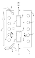
- the sole figure is a schematic representation of a device with which a method according to the invention can be carried out.
- the figure shows a device 1 with two boundaries 2a and 2b, which together enclose a evaporation zone 3.
- a plurality of electromagnetic radiation sources 4 are arranged, which can deliver an electromagnetic radiation 5.
- the arrangement and number of radiation sources 4 may vary depending on the requirements.
- two workpieces 6a and 6b are shown.
- the workpiece 6a is coated on all sides with a solvent-containing liquid paint layer 7a.
- the workpiece 6b is only partially coated with a corresponding lacquer layer 7b.
- the device 1 also has an air treatment system with supply air 8a and exhaust air 8b.
- This can be a fresh air system.
- a recirculation system may be provided, as indicated by the dashed arrow 9.
- the work piece 6a coated on all sides is assumed.
- This workpiece 6a has been provided on all sides with a lacquer layer in a coating process I not shown.
- the workpiece 6 a as indicated by the arrow A, introduced into the device 1.
- the evaporation II of the applied lacquer layer takes place.
- the workpiece 6a is passed through the evaporation zone 3.
- a moist and cool climate prevails due to the supply 8a and the removal 8b, corresponding to conditioned air.
- the movement of the conditioned air in the evaporation zone 3 takes place opposite to the direction of movement of the workpiece 6a through the evaporation zone 3. This is achieved in that the supply air 8a is blown in at the rear end of the device 1 in the direction of the workpiece 6a and consumed at the front end Air in the form of the exhaust air 8b is sucked away from the workpiece 6a.
- the radiation sources 4 irradiate the lacquer layer 7a with electromagnetic radiation 5, which may be infrared and / or microwave radiation. Thanks to the moist and cool climate, when the varnish layer 7a evaporates, its surface is prevented from drying out. The surface of the lacquer layer 7a remains permeable. Therefore, the lower volatiles of the lacquer layer can freely exit the lacquer when excited by the radiation 5.
- the workpiece exits the evaporation zone 3 at the rear end of the device 1. Then it will Workpiece, as indicated by arrow B, promoted to the actual drying process III.
- the evaporation of the partially coated workpiece 6b is similar to the just described evaporation of the workpiece 6a. However, the workpiece 6b is not irradiated at those locations where there is no paint. In order to achieve this, certain radiation sources 4 can simply remain switched off during the evaporation phase II. Alternatively, the device 1 can be designed specifically for the evaporation of the workpieces 6b, so that the arrangement of the radiation sources 4 is such that irradiation of uncoated workpiece parts is avoided.
Landscapes
- Engineering & Computer Science (AREA)
- Physics & Mathematics (AREA)
- Thermal Sciences (AREA)
- Chemical & Material Sciences (AREA)
- Combustion & Propulsion (AREA)
- Mechanical Engineering (AREA)
- General Engineering & Computer Science (AREA)
- Drying Of Solid Materials (AREA)
- Application Of Or Painting With Fluid Materials (AREA)
- Processing And Handling Of Plastics And Other Materials For Molding In General (AREA)
Abstract
Description
- Die Erfindung betrifft ein Verfahren und eine Vorrichtung zum Trocknen einer auf einem Werkstück aufgebrachten lösemittelhaltigen Lackschicht.
- Jeder Lack besteht aus einer filmbildenden Substanz -dem sogenannten Lackkörper oder Bindemittel- die in einem flüchtigen Lösungsmittel oder Lösungsmittelgemisch gelöst ist. Je nach Art des Lackes kommen dazu noch Pigmente, Füllstoffe, Sikkative, Weichmacher, Härter oder andere Additive.
Als Trocknung bezeichnet man bei den Lacken das Umwandeln der auf einen Körper aufgebrachten, flüssigen Lackschicht in einen festen Film, der den beschichteten Körper schützen und verschönern soll.
Während dieses Vorgangs finden Änderungen in den physikalischen und chemischen Eigenschaften der Lackschicht statt, die dem Film erst die gewünschten charakteristischen Eigenschaften verleihen. - Der Trocknungsvorgang findet durch Ablauf der folgenden Schritte statt: physikalische Trocknung (Verdunstung des Lösungsmittels) und Aushärtung der Schicht durch kolloidale Veränderungen und/oder chem. Vernetzungsreaktionen (Polymerisation, Polyaddition, Polykondensation), die nahtlos ineinander übergehen.
- Herkömmlicherweise realisiert man die physikalische Trocknung als ersten Schritt nach dem Lackauftrag, beginnend mit dem Abdunsten des Lösungsmittels aus der Lackschicht, indem das beschichtete Werkstück durch einen möglichst staubfreien Bereich bei Raumklima oder leicht erhöhter Lufttemperatur bis maximal 30 bis 40 °C hindurchgeführt wird. In dieser Abdunstzone soll sich die aufgetragene Lackschicht vergleichmäßigen und mit der Werkstückoberfläche verbinden. Eventuell sollen auch die Lackpigmente eine bestimmte Orientierung und Schichtung ausbilden. Außerdem soll bei diesem Abdunsten ein großer Teil der flüchtigen Bestandteile des Lackes verdunsten.
Im Anschluss an die Abdunstphase schließt sich der forcierte Trocknungs- oder auch Aushärtungsvorgang an. Dabei werden die restlichen flüchtigen Inhaltsstoffe ausgetrieben und die Vernetzungsreaktionen laufen ab. Dies kann ggf. unter Zuführung von Energie unter zeitweiliger Erhöhung der Temperatur von Werkstück und Lackschicht geschehen. - Während der ersten Stufe der Trocknung, also dem Abdunsten der Lackschicht, ist es entscheidend, dass die Lackschicht insbesondere an ihrer mit der Luft in Verbindung stehenden Oberfläche diffusionsoffen bleibt, da sonst unter der Oberfläche liegende flüchtige Bestandteile nicht mehr in ausreichendem Maße verdunsten können.
- Wenn die Oberfläche der Lackschicht in der Abdunstphase nicht ausreichend durchlässig bleibt, bleiben die flüchtigen Bestandteile teilweise innerhalb des Lackes "gefangen".
Dies erweist sich beim nachfolgenden forcierten Trocknungsprozess als nachteilig.
In der Tat verursachen die gefangenen Bestandteile durch die dort erfolgende verstärkte Energieeinwirkung Schichtfehler im Lack wie z.B. Blasen (den so genannten "Kochern"), Schwundrisse oder partielle Trübungen. - Es ist folglich eine Aufgabe der vorliegenden Erfindung, ein Verfahren und eine Vorrichtung zur Trocknung von Lackschichten vorzuschlagen, bei welchem die Bildung von Schichtfehlern bei der Trocknung zuverlässiger vermieden werden kann. Insbesondere soll in der Abdunstphase eine gute Verdunstung erreicht werden, indem die Durchlässigkeit der Lackoberfläche gewährleistet wird.
- Zur Lösung der soeben genannten Aufgabe schlägt die vorliegende Erfindung ein Verfahren zum Trocknen einer auf einem Werkstück aufgebrachten lösemittelhaltigen Lackschicht vor, wobei das Verfahren den folgenden Schritt aufweist:
- Zufuhr von auf Feuchte und Kühle konditionierter Luft auf das Werkstück bei gleichzeitigem Energieeintrag in die Lackschicht durch Einwirkung elektromagnetischer Strahlung.
- Durch die Zufuhr von feuchter und kühler Luft wird der Abdunstprozess an der Oberfläche der Lackschicht gebremst. Die Lackoberfläche wird kühl gehalten, sie kann während des Abdunstens nicht austrocknen, sondern bleibt feucht und dadurch durchlässig. Die Ausbildung einer störenden diffusionshemmenden Oberfläche wird vermieden. Gleichzeitig werden die flüchtigen Bestandteile unterhalb der Oberfläche durch die einfallende elektromagnetische Strahlung erregt und wirksam aus dem Lack herausgetrieben. Die elektromagnetische Strahlung bringt Energie in die Lackschicht ein, so dass das Verdunsten der enthaltenen flüchtigen Elemente über den gesamten Schichtquerschnitt gefördert wird.
- Im Rahmen der Erfindung sind unter lösemittelhaltigem Lack alle Lacke zu verstehen, die ein flüssiges Lösemittel oder auch Lösungsmittel enthalten. Bevorzugt handelt es sich bei dem Lösemittel um Wasser, es sind aber auch andere Lösemittel mitumfasst.
- Die konditionierte Luft ist eine Luft, die zur Verwendung für die Abdunstung vorgesehen ist und dementsprechend in ihrer Temperatur und Luftfeuchtigkeit angepasst und aufbereitet ist. Es handelt sich dabei also nicht um einfache Raum- oder Umgebungsluft.
- Erfindungsgemäß wird die konditionierte Luft auf das Werkstück zugeführt. Dies bedeutet bspw., dass die Luft auf das Werkstück gerichtet oder auf dieses aufgeblasen wird. Es sind auch weitere Arten der Luftzuführung denkbar. So kann z.B. die Luft in einen abgetrennten Raum eingeführt werden, in welchem sich das beschichtete Werkstück befindet. Wesentlich ist dabei lediglich, dass ein Austausch zwischen der zugeführten Luft und der Oberfläche der Lackschicht erfolgen kann. Die konditionierte Luft soll mit der Lackschicht in Kontakt treten können, d.h. die Luft soll mit der Lackschicht zusammengebracht werden.
- Der Energieeintrag in die Lackschicht wird dadurch erreicht, dass die Lackschicht mit elektromagnetischer Strahlung bestrahlt wird. Dies geschieht z.B. durch entsprechende Strahlungsquellen, deren Emissionen auf die beschichteten Werkstücke gerichtet sind. Die elektromagnetischen Wellen oder Strahlen dringen so in die Lackschicht ein und werden von dem im Lack enthaltenen Lösungsmittel absorbiert. Durch diese Energiezufuhr oder auch Erwärmung kann das Lösungsmittel über die durchlässige Oberfläche aus dem Lack entweichen.
- In einer bevorzugten Ausgestaltung des erfindungsgemäßen Verfahrens ist die konditionierte Luft auf eine Temperatur im Bereich von +1°C bis +18°C und/oder eine Luftfeuchte im Bereich von 50% bis 90% relative Feuchtigkeit konditioniert.
- Bei diesen Temperatur- und Feuchtigkeitswerten lässt sich die Oberfläche der Lackschicht besonders gut permeabel halten. Der Temperaturbereich von 1 bis 18 °C garantiert eine gute Kühlung und der Feuchtigkeitsbereich von 50 bis 90 % eine gute Befeuchtung der Oberfläche.
- Bevorzugt erfolgt der Energieeintrag auch in das Werkstück, d.h. die elektromagnetische Strahlung dringt auch zumindest teilweise direkt in das Werkstück ein und wird dort vom Werkstück aufgenommen. Durch die so erfolgende Erwärmung des Werkstückes wird die Verdunstung der flüchtigen Bestandteile in der Lackschicht von der Kontaktfläche Lackschicht/Werkstück noch zusätzlich gefördert.
- Weiterhin kann die konditionierte Luft wahlweise in Form von Frischluft oder in Form von Umluft zugeführt werden. Im Falle der Frischluftzufuhr wird ständig neue, unverbrauchte Luft dem Werkstück zugeführt. Falls ein Umluftsystem vorgesehen ist, findet lediglich eine ständig erneute Zufuhr von bereits zugeführter Luft statt, wobei diese Luft dabei immer wieder aufbereitet und konditioniert wird. Im Falle der Umluft geschieht also eine Umwälzung ein und derselben Luftmenge, während bei der Frischluftzufuhr laufend neue Luft eingebracht wird und verbrauchte Luft entsorgt wird.
- Vorzugsweise erfolgt dann nach dem Abdunstvorgang die weitere, forcierte Trocknung der Lackschicht mittels eines Düsentrockners. Da durch die erfindungsgemäße Abdunstung ein Großteil der flüchtigen Bestandteile unterhalb der Oberfläche der Lackschicht bereits entwichen ist, besteht auch bei der anschließenden schnellen und intensiven Trocknung durch den Düsentrockner keine Gefahr der Blasen- oder Rissbildung.
Das erfindungsgemäße Abdunstverfahren ermöglicht also in Verbindung mit der sich anschließenden forcierten Trocknung gegenüber herkömmlichen Verfahren kürzere Trocknungszeiten mit qualitativ besseren Beschichtungsergebnissen bei wesentlich verringertem Auftreten von trocknungsbedingten Schichtfehlern. - Es ist von Vorteil, wenn zur Erzeugung der elektromagnetischen Strahlung mindestens ein Infrarot-Strahler verwendet wird. Besonders bevorzugt wird ein Infrarot-Strahler mit einem auf die Absorptionskurve der flüchtigen Lackbestandteile gezielt abgestimmten Emissionsspektrum verwendet (im Bereich Emissionszahl >0,8 durch Resonanz der Strahlungsfrequenzen und der Eigenschwingungs-Frequenzen der Moleküle der flüchtigen Lackbestandteile). Dies erlaubt eine effiziente und verlustarme Energieübertragung in die Lackschicht, da durch die Abstimmung ein Großteil der ausgesandten Strahlung auch wie erwünscht vom Lösungsmittel im Lack absorbiert wird. Jedoch lassen sich, bei schlechterer Energieausnutzung, auch herkömmliche IR-Strahler ohne abgestimmtes Emissionsspektrum verwenden.
- Weiterhin kann zur Erzeugung der elektromagnetischen Strahlung auch mindestens ein Mikrowellengenerator, insbesondere ein Magnetron, verwendet werden. Dabei ist es auch denkbar, dass der Mikrowellengenerator zusammen mit einem Infrarotstrahler eingesetzt wird.
Ein Mikrowellengenerator kann aber auch anstelle eines Infrarotstrahlers eingesetzt werden. Ein Mikrowellengenerator ist insbesondere dann von Vorteil, wenn es sich bei dem abzudunstenden Lack um einen Lack mit Wasser als Lösungsmittel handelt. In der Tat können Wassermoleküle im flüssigen Aggregatzustand durch Mikrowellenstrahlung auf Grund ihrer elektrischen Dipol- Eigenschaft effektiv zu Schwingungen angeregt werden, wobei Wärmeenergie freigesetzt wird. Dies erlaubt eine besonders effiziente Energieübertragung in die wasserhaltige Lackschicht. Die Frequenz des Mikrowellengenerators liegt vorzugsweise im, in Europa freigegeben, Bereich um 2,45 GHz. - Es ist aber auch denkbar, eine andere freigegebene, höhere Frequenz anzuwenden.
Besonders bevorzugt liegt die Frequenz des Mikrowellengenerators im Bereich zwischen 2,45 GHz und 4,9 GHz. - Schließlich schlägt die vorliegende Erfindung zur Lösung der oben genannten Aufgabe auch eine Vorrichtung zur Durchführung eines oder mehrerer der soeben beschriebenen Verfahren vor.
- Die einzige Figur ist eine schematische Darstellung einer Vorrichtung, mit welcher ein erfindungsgemäßes Verfahren durchgeführt werden kann.
- Die Figur zeigt eine Einrichtung 1 mit zwei Abgrenzungen 2a und 2b, die gemeinsam eine Abdunstzone 3 umschließen. Innerhalb der Abdunstzone 3 sind mehrere elektromagnetische Strahlungsquellen 4 angeordnet, die eine elektromagnetische Strahlung 5 abgeben können. Die Anordnung und Anzahl der Strahlungsquellen 4 kann je nach Anforderung unterschiedlich ausfallen. Zwischen den Strahlungsquellen 4 sind zwei Werkstücke 6a und 6b dargestellt. Das Werkstück 6a ist allseitig mit einer lösungsmittelhaltigen Flüssiglackschicht 7a überzogen. Dagegen ist das Werkstück 6b nur teilweise mit einer entsprechenden Lackschicht 7b beschichtet.
- Die Einrichtung 1 verfügt außerdem über eine Luftaufbereitungsanlage mit Zuluft 8a und Abluft 8b. Dabei kann es sich um eine Frischluftanlage handeln. Alternativ kann auch ein Umluftsystem vorgesehen sein, wie es durch den gestrichelten Pfeil 9 angedeutet ist.
- Im Folgenden wird nun die Funktionsweise der Einrichtung 1 erläutert.
- Zunächst wird von dem allseitig beschichteten Werkstück 6a ausgegangen. Dieses Werkstück 6a wurde in einem nicht weiter dargestellten Beschichtungsprozess I allseitig mit einer Lackschicht versehen. Sodann wird das Werkstück 6a, wie durch den Pfeil A angedeutet, in die Einrichtung 1 eingeführt. In der Einrichtung 1 erfolgt die Abdunstung II der aufgetragenen Lackschicht. Hierzu wird das Werkstück 6a durch die Abdunstzone 3 hindurchgeführt.
- In der Abdunstzone 3 herrscht durch die Zufuhr 8a und die Abfuhr 8b entsprechend konditionierter Luft ein feuchtes und kühles Klima. Die Bewegung der konditionierten Luft in der Abdunstzone 3 erfolgt entgegengesetzt zu der Bewegungsrichtung des Werkstückes 6a durch die Abdunstzone 3. Dies wird dadurch erreicht, dass die Zuluft 8a am hinteren Ende der Einrichtung 1 in Richtung des Werkstückes 6a eingeblasen wird und am vorderen Ende die verbrauchte Luft in Form der Abluft 8b vom Werkstück 6a weg abgesaugt wird.
- Gleichzeitig erfolgt durch die Strahlungsquellen 4 eine Bestrahlung der Lackschicht 7a mit elektromagnetischer Strahlung 5, wobei es sich dabei um Infrarot- und/oder Mikrowellenstrahlung handeln kann. Dank des feuchten und kühlen Klimas wird beim Abdunsten der Lackschicht 7a ein Austrocknen deren Oberfläche verhindert. Die Oberfläche der Lackschicht 7a bleibt durchlässig. Daher können die tiefergelegenen flüchtigen Bestandteile der Lackschicht ungehindert aus dem Lack austreten, wenn sie durch die Strahlung 5 angeregt werden.
- Nachdem die Lackschicht 7a durch das Zusammenwirken der feuchten und kühlen Luft sowie der Bestrahlung gut abgedunstet ist, tritt das Werkstück am hinteren Ende der Einrichtung 1 aus der Abdunstzone 3 aus. Sodann wird das Werkstück, wie es Pfeil B andeutet, zum eigentlichen Trocknungsvorgang III befördert.
- Die Abdunstung des nur teilweise beschichteten Werkstückes 6b erfolgt ähnlich zu der soeben beschriebenen Abdunstung des Werkstückes 6a. Allerdings wird das Werkstück 6b an denjenigen Stellen nicht bestrahlt, an welchen sich kein Lack befindet. Um dies zu erreichen, können bestimmte Strahlungsquellen 4 während der Abdunstungsphase II einfach ausgeschaltet bleiben. Alternativ kann die Einrichtung 1 speziell für die Abdunstung der Werkstücke 6b ausgelegt sein, so dass die Anordnung der Strahlungsquellen 4 derart ist, dass eine Bestrahlung unbeschichteter Werkstückteile vermieden wird.
- Mit dem erfindungsgemäßen Verfahren und der erfindungsgemäßen Vorrichtung wird eine wesentlich bessere und gründlichere Abdunstung von lösungsmittelhaltigen Lacken erzielt. So kann beim sich anschließenden Trocknungsprozess mit verstärkter Energieeinwirkung die Bildung von Schichtfehlern wirksam vermieden werden.
-
- 1
- Abdunsteinrichtung
- 2a
- Obere Abgrenzung
- 2b
- Untere Abgrenzung
- 3
- Abdunstzone
- 4
- Strahlungsquelle
- 5
- Strahlung
- 6a
- Allseitig beschichtetes Werkstück
- 6b
- Teilweise beschichtetes Werkstück
- 7a, 7b
- Lackschicht
- 8a
- Zuluft
- 8b
- Abluft
- 9
- Umluft
- I
- Beschichtung
- II
- Abdunstung
- III
- Trocknung
Claims (10)
- Verfahren zum Trocknen einer auf einem Werkstück (6) aufgebrachten lösemittelhaltigen Lackschicht (7), gekennzeichnet durch den folgenden Schritt:- Zufuhr (8a) von auf Feuchte und Kühle konditionierter Luft auf das Werkstück (6) bei gleichzeitigem Energieeintrag in die Lackschicht (7) durch Einwirkung elektromagnetischer Strahlung (5).
- Verfahren nach Anspruch 1, dadurch gekennzeichnet, dass die konditionierte Luft auf eine Temperatur im Bereich von +1°C bis +18°C und/oder eine Luftfeuchte im Bereich von 50% bis 90% relative Feuchtigkeit konditioniert ist.
- Verfahren nach Anspruch 1 oder 2, dadurch gekennzeichnet, dass der Energieeintrag auch in das Werkstück (6) erfolgt.
- Verfahren nach einem der vorherigen Ansprüche, dadurch gekennzeichnet, dass die konditionierte Luft in Form von Frischluft oder Umluft (9) zugeführt wird.
- Verfahren nach einem der vorherigen Ansprüche, gekennzeichnet durch den weiteren Schritt:- Trocknung (III) der Lackschicht (7) mittels eines Düsentrockners.
- Verfahren nach einem der vorherigen Ansprüche, dadurch gekennzeichnet, dass zur Erzeugung der elektromagnetischen Strahlung (5) mindestens ein Infrarot-Strahler verwendet wird.
- Verfahren nach Anspruch 6, dadurch gekennzeichnet, dass ein Infrarot-Strahler mit einem auf die Absorptionskurve der flüchtigen Lackbestandteile besonders abgestimmten Emissionsspektrum verwendet wird.
- Verfahren nach einem der vorherigen Ansprüche, dadurch gekennzeichnet, dass zur Erzeugung der elektromagnetischen Strahlung mindestens ein Mikrowellengenerator, insbesondere ein Magnetron, verwendet wird.
- Verfahren nach Anspruch 8, dadurch gekennzeichnet, dass der Frequenzbereich des Mikrowellengenerators bei 2,45 GHz oder höher liegt.
- Vorrichtung zur Durchführung eines Verfahrens nach einem der Ansprüche 1 bis 9.
Priority Applications (1)
| Application Number | Priority Date | Filing Date | Title |
|---|---|---|---|
| PL06000428T PL1681102T3 (pl) | 2005-01-13 | 2006-01-10 | Sposób i urządzenie do suszenia warstw lakieru |
Applications Claiming Priority (1)
| Application Number | Priority Date | Filing Date | Title |
|---|---|---|---|
| DE102005001683A DE102005001683B4 (de) | 2005-01-13 | 2005-01-13 | Verfahren und Vorrichtung zum Trocknen von Lackschichten |
Publications (2)
| Publication Number | Publication Date |
|---|---|
| EP1681102A1 true EP1681102A1 (de) | 2006-07-19 |
| EP1681102B1 EP1681102B1 (de) | 2011-09-28 |
Family
ID=36123067
Family Applications (1)
| Application Number | Title | Priority Date | Filing Date |
|---|---|---|---|
| EP06000428A Expired - Lifetime EP1681102B1 (de) | 2005-01-13 | 2006-01-10 | Verfahren und Vorrichtung zum Trocknen von Lackschichten |
Country Status (9)
| Country | Link |
|---|---|
| US (1) | US20060177595A1 (de) |
| EP (1) | EP1681102B1 (de) |
| KR (1) | KR20060082800A (de) |
| CN (1) | CN1803313B (de) |
| AT (1) | ATE526092T1 (de) |
| CA (1) | CA2530998C (de) |
| DE (1) | DE102005001683B4 (de) |
| ES (1) | ES2371480T3 (de) |
| PL (1) | PL1681102T3 (de) |
Cited By (3)
| Publication number | Priority date | Publication date | Assignee | Title |
|---|---|---|---|---|
| EP2466237A3 (de) * | 2010-12-15 | 2014-11-05 | Heinz-Glas GmbH & Co. KGaA | Infrarot-Trocknungsanlage |
| EP2225044B1 (de) * | 2007-12-13 | 2016-03-02 | Dürr Systems GmbH | Kühlvorrichtung und verfahren zum kühlen von gegenständen aus einer beschichtungseinrichtung |
| EP2808095A4 (de) * | 2012-01-23 | 2016-05-11 | Ngk Insulators Ltd | Trocknungsverfahren und beschichtungsfilm-trocknungsofen für einen auf einer pet-filmoberfläche gebildeten beschichtungsfilm |
Families Citing this family (6)
| Publication number | Priority date | Publication date | Assignee | Title |
|---|---|---|---|---|
| US20070143283A1 (en) * | 2005-12-09 | 2007-06-21 | Stephan Spencer | Method of optimizing search engine rankings through a proxy website |
| JP5171109B2 (ja) * | 2007-05-25 | 2013-03-27 | 大同メタル工業株式会社 | 樹脂被覆摺動部材の製造方法 |
| ITVI20120338A1 (it) * | 2012-12-19 | 2014-06-20 | Cartigliano Off Spa | Metodo ed apparato per l'essicatura di pelli durante il processo di rifinizione |
| AT523061B1 (de) * | 2019-10-16 | 2021-05-15 | Ess Holding Gmbh | Verfahren zur Oberflächenbeschichtung von Werkstücken |
| WO2021107062A1 (ja) | 2019-11-28 | 2021-06-03 | 積水化学工業株式会社 | 合わせガラス用中間膜、合わせガラス、及び画像表示システム |
| KR102783260B1 (ko) * | 2021-09-30 | 2025-03-17 | 해성디에스 주식회사 | 릴투릴 부품 건조 장치 |
Citations (3)
| Publication number | Priority date | Publication date | Assignee | Title |
|---|---|---|---|---|
| US5288526A (en) * | 1993-02-11 | 1994-02-22 | Nordson Corporation | Ventilated curing oven and preheat flash zone system for curing coatings on circuit boards |
| DE20202512U1 (de) * | 2002-02-19 | 2002-06-27 | Kurpisch, Bernward-Josef, 22529 Hamburg | Vorrichtung zum Behandeln einer Materialbahn mit einem gasförmigen Medium und Strahlungsenergie |
| WO2005023437A2 (en) * | 2003-09-03 | 2005-03-17 | E.I. Dupont De Nemours And Company | Multi-stage processes for drying and curing substrates coated with aqueous basecoat and a topcoat |
Family Cites Families (11)
| Publication number | Priority date | Publication date | Assignee | Title |
|---|---|---|---|---|
| US4497121A (en) * | 1981-05-04 | 1985-02-05 | Polaroid Corporation | Process simulator |
| DE4318471A1 (de) * | 1993-06-03 | 1994-12-08 | Thomae Gmbh Dr K | Eintopf-Mischer-Granulator-Trockner |
| AT403518B (de) * | 1993-12-01 | 1998-03-25 | Hoffmann Friedrich | Verfahren und einrichtung zum trocknen und/oder aushärten von beschichtungen |
| DE19625789B4 (de) * | 1995-07-08 | 2007-11-22 | Volkswagen Ag | Verfahren zum Beschichten einer Karosserie |
| US5659972A (en) * | 1995-10-06 | 1997-08-26 | Avery Dennison Corporation | Apparatus and method for drying or curing web materials and coatings |
| DE19807643C2 (de) * | 1998-02-23 | 2000-01-05 | Industrieservis Ges Fuer Innov | Verfahren und Vorrichtung zum Trocknen eines Trocknungsgutes an der Oberfläche eines schnell geförderten Trägermaterials, insbesondere zum Druckfarbentrocknen |
| DE19857940C1 (de) * | 1998-12-16 | 2000-07-27 | Herberts Gmbh | Verfahren zur Mehrschichtlackierung mit strahlenhärtbaren Beschichtungsmitteln |
| DE19906247A1 (de) * | 1999-02-15 | 2000-08-17 | Herberts Gmbh & Co Kg | Verfahren zur Herstellung zweischichtiger Automobildecklackierungen |
| DE19907681A1 (de) * | 1999-02-23 | 2000-08-24 | Juergen Wahrmund | Verfahren und Vorrichtung zum Behandeln einer Materialbahn mittels Strahlungsenergie |
| US6291027B1 (en) * | 1999-05-26 | 2001-09-18 | Ppg Industries Ohio, Inc. | Processes for drying and curing primer coating compositions |
| US20050064337A1 (en) * | 2003-04-21 | 2005-03-24 | Fuji Photo Film Co., Ltd. | Image forming method and image exposure device |
-
2005
- 2005-01-13 DE DE102005001683A patent/DE102005001683B4/de not_active Expired - Fee Related
- 2005-12-20 CA CA2530998A patent/CA2530998C/en not_active Expired - Lifetime
-
2006
- 2006-01-06 US US11/327,628 patent/US20060177595A1/en not_active Abandoned
- 2006-01-10 EP EP06000428A patent/EP1681102B1/de not_active Expired - Lifetime
- 2006-01-10 AT AT06000428T patent/ATE526092T1/de active
- 2006-01-10 ES ES06000428T patent/ES2371480T3/es not_active Expired - Lifetime
- 2006-01-10 PL PL06000428T patent/PL1681102T3/pl unknown
- 2006-01-11 KR KR1020060003010A patent/KR20060082800A/ko not_active Withdrawn
- 2006-01-11 CN CN2006100007792A patent/CN1803313B/zh not_active Expired - Fee Related
Patent Citations (3)
| Publication number | Priority date | Publication date | Assignee | Title |
|---|---|---|---|---|
| US5288526A (en) * | 1993-02-11 | 1994-02-22 | Nordson Corporation | Ventilated curing oven and preheat flash zone system for curing coatings on circuit boards |
| DE20202512U1 (de) * | 2002-02-19 | 2002-06-27 | Kurpisch, Bernward-Josef, 22529 Hamburg | Vorrichtung zum Behandeln einer Materialbahn mit einem gasförmigen Medium und Strahlungsenergie |
| WO2005023437A2 (en) * | 2003-09-03 | 2005-03-17 | E.I. Dupont De Nemours And Company | Multi-stage processes for drying and curing substrates coated with aqueous basecoat and a topcoat |
Cited By (3)
| Publication number | Priority date | Publication date | Assignee | Title |
|---|---|---|---|---|
| EP2225044B1 (de) * | 2007-12-13 | 2016-03-02 | Dürr Systems GmbH | Kühlvorrichtung und verfahren zum kühlen von gegenständen aus einer beschichtungseinrichtung |
| EP2466237A3 (de) * | 2010-12-15 | 2014-11-05 | Heinz-Glas GmbH & Co. KGaA | Infrarot-Trocknungsanlage |
| EP2808095A4 (de) * | 2012-01-23 | 2016-05-11 | Ngk Insulators Ltd | Trocknungsverfahren und beschichtungsfilm-trocknungsofen für einen auf einer pet-filmoberfläche gebildeten beschichtungsfilm |
Also Published As
| Publication number | Publication date |
|---|---|
| ATE526092T1 (de) | 2011-10-15 |
| DE102005001683A1 (de) | 2006-07-27 |
| CA2530998C (en) | 2011-11-29 |
| PL1681102T3 (pl) | 2012-02-29 |
| CN1803313B (zh) | 2010-12-08 |
| CA2530998A1 (en) | 2006-07-13 |
| CN1803313A (zh) | 2006-07-19 |
| DE102005001683B4 (de) | 2010-01-14 |
| US20060177595A1 (en) | 2006-08-10 |
| ES2371480T3 (es) | 2012-01-03 |
| EP1681102B1 (de) | 2011-09-28 |
| KR20060082800A (ko) | 2006-07-19 |
Similar Documents
| Publication | Publication Date | Title |
|---|---|---|
| DE3833225C2 (de) | ||
| DE3904111C2 (de) | ||
| EP1681102B1 (de) | Verfahren und Vorrichtung zum Trocknen von Lackschichten | |
| EP2047916A2 (de) | Lichthärtung von Strahlungshärtbaren Massen unter Schutzgas | |
| WO2003038923A1 (de) | Verfahren zur trocknung von schichten organischer hablaiter, letier oder farbfilter mittels ir und/oder nir-strahlung | |
| DE69400649T2 (de) | Verbesserungen in Bezug auf härtende Beschichtungsstoffe | |
| EP4302341A1 (de) | Verfahren und vorrichtung zur herstellung von batteriekomponenten auf einem flexiblen träger | |
| DE19857940C1 (de) | Verfahren zur Mehrschichtlackierung mit strahlenhärtbaren Beschichtungsmitteln | |
| DE112010000464T5 (de) | Verfahren und vorrichtung zum lackaushärten | |
| DE3821848C1 (de) | ||
| DD244704A5 (de) | Laser zum haerten von ueberzuegen und farben | |
| DE1571175C3 (de) | Verfahren zum Aufbringen von Überzügen durch Aushärtung von ungesättigten Polyesterharzmassen | |
| EP3936236B1 (de) | Verfahren zur beschichtung von objekten und anlage zur lackierung von objekten | |
| DE2059352A1 (de) | Verfahren zur Herstellung von UEberzuegen auf der Grundlage von Alkydharzen und waessrige Alkydharz-Dispersionen | |
| EP1395784B1 (de) | Verfahren und einrichtung zum trocknen | |
| DE19857941A1 (de) | Verfahren zur Mehrschichtlackierung | |
| DE10323761B4 (de) | Vorrichtung zur Aufbringung und Trocknung einer Beschichtung auf einer Leiterplatte | |
| DE19933960C1 (de) | Härteofen und Verfahren zum Härten einer Beschichtung | |
| DE852939C (de) | Apparat zur Akklimatisation bzw. Haerten und Akklimatisation von Faserplatten | |
| EP1327844A2 (de) | Verfahren und Vorrichtung zur Behandlung eines Beschichtungsstoffes auf einem Substrat und/oder eines Substrats | |
| DD284771A5 (de) | Vorrichtung und einrichtung zum vortrocknen oder durchhaerten von fotolackbeschichteten leiterplatten | |
| WO2000038487A1 (de) | Herstellung von photoresistbeschichtungen | |
| DE102022103993A1 (de) | Verfahren zum Härten von Beschichtungen in einer Druckmaschine mittels unterschiedlich angesteuerter Gasentladungslampen | |
| DE202023103004U1 (de) | Umluft-Prozess-System | |
| DE102021123590A1 (de) | Verfahren zum Härten von gedruckten Beschichtungen mittels Elektronenstrahlung |
Legal Events
| Date | Code | Title | Description |
|---|---|---|---|
| PUAI | Public reference made under article 153(3) epc to a published international application that has entered the european phase |
Free format text: ORIGINAL CODE: 0009012 |
|
| AK | Designated contracting states |
Kind code of ref document: A1 Designated state(s): AT BE BG CH CY CZ DE DK EE ES FI FR GB GR HU IE IS IT LI LT LU LV MC NL PL PT RO SE SI SK TR |
|
| AX | Request for extension of the european patent |
Extension state: AL BA HR MK YU |
|
| 17P | Request for examination filed |
Effective date: 20061129 |
|
| AKX | Designation fees paid |
Designated state(s): AT BE BG CH CY CZ DE DK EE ES FI FR GB GR HU IE IS IT LI LT LU LV MC NL PL PT RO SE SI SK TR |
|
| 17Q | First examination report despatched |
Effective date: 20080130 |
|
| GRAP | Despatch of communication of intention to grant a patent |
Free format text: ORIGINAL CODE: EPIDOSNIGR1 |
|
| GRAS | Grant fee paid |
Free format text: ORIGINAL CODE: EPIDOSNIGR3 |
|
| GRAA | (expected) grant |
Free format text: ORIGINAL CODE: 0009210 |
|
| AK | Designated contracting states |
Kind code of ref document: B1 Designated state(s): AT BE BG CH CY CZ DE DK EE ES FI FR GB GR HU IE IS IT LI LT LU LV MC NL PL PT RO SE SI SK TR |
|
| REG | Reference to a national code |
Ref country code: GB Ref legal event code: FG4D Free format text: NOT ENGLISH |
|
| REG | Reference to a national code |
Ref country code: CH Ref legal event code: EP |
|
| REG | Reference to a national code |
Ref country code: IE Ref legal event code: FG4D |
|
| REG | Reference to a national code |
Ref country code: DE Ref legal event code: R096 Ref document number: 502006010249 Country of ref document: DE Effective date: 20111215 |
|
| REG | Reference to a national code |
Ref country code: ES Ref legal event code: FG2A Ref document number: 2371480 Country of ref document: ES Kind code of ref document: T3 Effective date: 20120103 |
|
| REG | Reference to a national code |
Ref country code: NL Ref legal event code: VDEP Effective date: 20110928 |
|
| PG25 | Lapsed in a contracting state [announced via postgrant information from national office to epo] |
Ref country code: SE Free format text: LAPSE BECAUSE OF FAILURE TO SUBMIT A TRANSLATION OF THE DESCRIPTION OR TO PAY THE FEE WITHIN THE PRESCRIBED TIME-LIMIT Effective date: 20110928 Ref country code: FI Free format text: LAPSE BECAUSE OF FAILURE TO SUBMIT A TRANSLATION OF THE DESCRIPTION OR TO PAY THE FEE WITHIN THE PRESCRIBED TIME-LIMIT Effective date: 20110928 Ref country code: LT Free format text: LAPSE BECAUSE OF FAILURE TO SUBMIT A TRANSLATION OF THE DESCRIPTION OR TO PAY THE FEE WITHIN THE PRESCRIBED TIME-LIMIT Effective date: 20110928 |
|
| LTIE | Lt: invalidation of european patent or patent extension |
Effective date: 20110928 |
|
| PG25 | Lapsed in a contracting state [announced via postgrant information from national office to epo] |
Ref country code: CY Free format text: LAPSE BECAUSE OF FAILURE TO SUBMIT A TRANSLATION OF THE DESCRIPTION OR TO PAY THE FEE WITHIN THE PRESCRIBED TIME-LIMIT Effective date: 20110928 Ref country code: LV Free format text: LAPSE BECAUSE OF FAILURE TO SUBMIT A TRANSLATION OF THE DESCRIPTION OR TO PAY THE FEE WITHIN THE PRESCRIBED TIME-LIMIT Effective date: 20110928 Ref country code: SI Free format text: LAPSE BECAUSE OF FAILURE TO SUBMIT A TRANSLATION OF THE DESCRIPTION OR TO PAY THE FEE WITHIN THE PRESCRIBED TIME-LIMIT Effective date: 20110928 Ref country code: GR Free format text: LAPSE BECAUSE OF FAILURE TO SUBMIT A TRANSLATION OF THE DESCRIPTION OR TO PAY THE FEE WITHIN THE PRESCRIBED TIME-LIMIT Effective date: 20111229 |
|
| REG | Reference to a national code |
Ref country code: PL Ref legal event code: T3 |
|
| REG | Reference to a national code |
Ref country code: IE Ref legal event code: FD4D |
|
| PG25 | Lapsed in a contracting state [announced via postgrant information from national office to epo] |
Ref country code: SK Free format text: LAPSE BECAUSE OF FAILURE TO SUBMIT A TRANSLATION OF THE DESCRIPTION OR TO PAY THE FEE WITHIN THE PRESCRIBED TIME-LIMIT Effective date: 20110928 Ref country code: CZ Free format text: LAPSE BECAUSE OF FAILURE TO SUBMIT A TRANSLATION OF THE DESCRIPTION OR TO PAY THE FEE WITHIN THE PRESCRIBED TIME-LIMIT Effective date: 20110928 Ref country code: IS Free format text: LAPSE BECAUSE OF FAILURE TO SUBMIT A TRANSLATION OF THE DESCRIPTION OR TO PAY THE FEE WITHIN THE PRESCRIBED TIME-LIMIT Effective date: 20120128 |
|
| PG25 | Lapsed in a contracting state [announced via postgrant information from national office to epo] |
Ref country code: EE Free format text: LAPSE BECAUSE OF FAILURE TO SUBMIT A TRANSLATION OF THE DESCRIPTION OR TO PAY THE FEE WITHIN THE PRESCRIBED TIME-LIMIT Effective date: 20110928 Ref country code: NL Free format text: LAPSE BECAUSE OF FAILURE TO SUBMIT A TRANSLATION OF THE DESCRIPTION OR TO PAY THE FEE WITHIN THE PRESCRIBED TIME-LIMIT Effective date: 20110928 Ref country code: PT Free format text: LAPSE BECAUSE OF FAILURE TO SUBMIT A TRANSLATION OF THE DESCRIPTION OR TO PAY THE FEE WITHIN THE PRESCRIBED TIME-LIMIT Effective date: 20120130 Ref country code: RO Free format text: LAPSE BECAUSE OF FAILURE TO SUBMIT A TRANSLATION OF THE DESCRIPTION OR TO PAY THE FEE WITHIN THE PRESCRIBED TIME-LIMIT Effective date: 20110928 |
|
| BERE | Be: lapsed |
Owner name: VENJAKOB MASCHINENBAU G.M.B.H. & CO. KG Effective date: 20120131 |
|
| PG25 | Lapsed in a contracting state [announced via postgrant information from national office to epo] |
Ref country code: IE Free format text: LAPSE BECAUSE OF FAILURE TO SUBMIT A TRANSLATION OF THE DESCRIPTION OR TO PAY THE FEE WITHIN THE PRESCRIBED TIME-LIMIT Effective date: 20110928 Ref country code: DK Free format text: LAPSE BECAUSE OF FAILURE TO SUBMIT A TRANSLATION OF THE DESCRIPTION OR TO PAY THE FEE WITHIN THE PRESCRIBED TIME-LIMIT Effective date: 20110928 |
|
| PLBE | No opposition filed within time limit |
Free format text: ORIGINAL CODE: 0009261 |
|
| STAA | Information on the status of an ep patent application or granted ep patent |
Free format text: STATUS: NO OPPOSITION FILED WITHIN TIME LIMIT |
|
| PG25 | Lapsed in a contracting state [announced via postgrant information from national office to epo] |
Ref country code: MC Free format text: LAPSE BECAUSE OF NON-PAYMENT OF DUE FEES Effective date: 20120131 |
|
| REG | Reference to a national code |
Ref country code: CH Ref legal event code: PL |
|
| 26N | No opposition filed |
Effective date: 20120629 |
|
| GBPC | Gb: european patent ceased through non-payment of renewal fee |
Effective date: 20120110 |
|
| REG | Reference to a national code |
Ref country code: DE Ref legal event code: R097 Ref document number: 502006010249 Country of ref document: DE Effective date: 20120629 |
|
| PG25 | Lapsed in a contracting state [announced via postgrant information from national office to epo] |
Ref country code: LI Free format text: LAPSE BECAUSE OF NON-PAYMENT OF DUE FEES Effective date: 20120131 Ref country code: CH Free format text: LAPSE BECAUSE OF NON-PAYMENT OF DUE FEES Effective date: 20120131 Ref country code: GB Free format text: LAPSE BECAUSE OF NON-PAYMENT OF DUE FEES Effective date: 20120110 |
|
| PG25 | Lapsed in a contracting state [announced via postgrant information from national office to epo] |
Ref country code: BE Free format text: LAPSE BECAUSE OF NON-PAYMENT OF DUE FEES Effective date: 20120131 |
|
| REG | Reference to a national code |
Ref country code: AT Ref legal event code: MM01 Ref document number: 526092 Country of ref document: AT Kind code of ref document: T Effective date: 20120110 |
|
| PG25 | Lapsed in a contracting state [announced via postgrant information from national office to epo] |
Ref country code: AT Free format text: LAPSE BECAUSE OF NON-PAYMENT OF DUE FEES Effective date: 20120110 Ref country code: BG Free format text: LAPSE BECAUSE OF FAILURE TO SUBMIT A TRANSLATION OF THE DESCRIPTION OR TO PAY THE FEE WITHIN THE PRESCRIBED TIME-LIMIT Effective date: 20111228 |
|
| PG25 | Lapsed in a contracting state [announced via postgrant information from national office to epo] |
Ref country code: TR Free format text: LAPSE BECAUSE OF FAILURE TO SUBMIT A TRANSLATION OF THE DESCRIPTION OR TO PAY THE FEE WITHIN THE PRESCRIBED TIME-LIMIT Effective date: 20110928 |
|
| PG25 | Lapsed in a contracting state [announced via postgrant information from national office to epo] |
Ref country code: LU Free format text: LAPSE BECAUSE OF NON-PAYMENT OF DUE FEES Effective date: 20120110 |
|
| PG25 | Lapsed in a contracting state [announced via postgrant information from national office to epo] |
Ref country code: HU Free format text: LAPSE BECAUSE OF FAILURE TO SUBMIT A TRANSLATION OF THE DESCRIPTION OR TO PAY THE FEE WITHIN THE PRESCRIBED TIME-LIMIT Effective date: 20060110 |
|
| REG | Reference to a national code |
Ref country code: FR Ref legal event code: PLFP Year of fee payment: 11 |
|
| REG | Reference to a national code |
Ref country code: FR Ref legal event code: PLFP Year of fee payment: 12 |
|
| PGFP | Annual fee paid to national office [announced via postgrant information from national office to epo] |
Ref country code: FR Payment date: 20170124 Year of fee payment: 12 |
|
| PGFP | Annual fee paid to national office [announced via postgrant information from national office to epo] |
Ref country code: ES Payment date: 20170124 Year of fee payment: 12 |
|
| PGFP | Annual fee paid to national office [announced via postgrant information from national office to epo] |
Ref country code: PL Payment date: 20180103 Year of fee payment: 13 |
|
| PG25 | Lapsed in a contracting state [announced via postgrant information from national office to epo] |
Ref country code: FR Free format text: LAPSE BECAUSE OF NON-PAYMENT OF DUE FEES Effective date: 20180131 |
|
| REG | Reference to a national code |
Ref country code: FR Ref legal event code: ST Effective date: 20180928 |
|
| PGFP | Annual fee paid to national office [announced via postgrant information from national office to epo] |
Ref country code: IT Payment date: 20190121 Year of fee payment: 14 Ref country code: DE Payment date: 20190128 Year of fee payment: 14 |
|
| REG | Reference to a national code |
Ref country code: ES Ref legal event code: FD2A Effective date: 20190730 |
|
| PG25 | Lapsed in a contracting state [announced via postgrant information from national office to epo] |
Ref country code: ES Free format text: LAPSE BECAUSE OF NON-PAYMENT OF DUE FEES Effective date: 20180111 |
|
| REG | Reference to a national code |
Ref country code: DE Ref legal event code: R119 Ref document number: 502006010249 Country of ref document: DE |
|
| PG25 | Lapsed in a contracting state [announced via postgrant information from national office to epo] |
Ref country code: PL Free format text: LAPSE BECAUSE OF NON-PAYMENT OF DUE FEES Effective date: 20190110 |
|
| PG25 | Lapsed in a contracting state [announced via postgrant information from national office to epo] |
Ref country code: DE Free format text: LAPSE BECAUSE OF NON-PAYMENT OF DUE FEES Effective date: 20200801 |
|
| PG25 | Lapsed in a contracting state [announced via postgrant information from national office to epo] |
Ref country code: IT Free format text: LAPSE BECAUSE OF NON-PAYMENT OF DUE FEES Effective date: 20200110 |