EP1682394B1 - Fire protection wall - Google Patents
Fire protection wall Download PDFInfo
- Publication number
- EP1682394B1 EP1682394B1 EP04790223A EP04790223A EP1682394B1 EP 1682394 B1 EP1682394 B1 EP 1682394B1 EP 04790223 A EP04790223 A EP 04790223A EP 04790223 A EP04790223 A EP 04790223A EP 1682394 B1 EP1682394 B1 EP 1682394B1
- Authority
- EP
- European Patent Office
- Prior art keywords
- wall
- fire protection
- frame
- protection wall
- gap
- Prior art date
- Legal status (The legal status is an assumption and is not a legal conclusion. Google has not performed a legal analysis and makes no representation as to the accuracy of the status listed.)
- Expired - Lifetime
Links
- 239000000463 material Substances 0.000 claims abstract description 37
- 239000003566 sealing material Substances 0.000 claims abstract description 31
- 238000004519 manufacturing process Methods 0.000 claims abstract description 9
- 238000000034 method Methods 0.000 claims abstract description 7
- 230000008569 process Effects 0.000 claims abstract description 7
- 238000007789 sealing Methods 0.000 claims description 25
- 238000002955 isolation Methods 0.000 claims description 16
- 238000009432 framing Methods 0.000 claims description 2
- 239000000779 smoke Substances 0.000 abstract description 11
- 239000013013 elastic material Substances 0.000 description 14
- 238000009413 insulation Methods 0.000 description 5
- 230000009970 fire resistant effect Effects 0.000 description 4
- 230000008901 benefit Effects 0.000 description 3
- 238000010276 construction Methods 0.000 description 3
- 230000002401 inhibitory effect Effects 0.000 description 3
- 230000009977 dual effect Effects 0.000 description 2
- 229920001971 elastomer Polymers 0.000 description 2
- 239000011521 glass Substances 0.000 description 2
- 239000005060 rubber Substances 0.000 description 2
- 239000000565 sealant Substances 0.000 description 2
- 206010003497 Asphyxia Diseases 0.000 description 1
- 239000000853 adhesive Substances 0.000 description 1
- 230000001070 adhesive effect Effects 0.000 description 1
- 239000004020 conductor Substances 0.000 description 1
- 230000006872 improvement Effects 0.000 description 1
- 239000012774 insulation material Substances 0.000 description 1
- 231100000572 poisoning Toxicity 0.000 description 1
- 230000000607 poisoning effect Effects 0.000 description 1
- 230000009467 reduction Effects 0.000 description 1
- 230000000717 retained effect Effects 0.000 description 1
- 229920002379 silicone rubber Polymers 0.000 description 1
- 239000004945 silicone rubber Substances 0.000 description 1
- 230000007480 spreading Effects 0.000 description 1
- XLYOFNOQVPJJNP-UHFFFAOYSA-N water Substances O XLYOFNOQVPJJNP-UHFFFAOYSA-N 0.000 description 1
Images

Classifications
-
- B—PERFORMING OPERATIONS; TRANSPORTING
- B61—RAILWAYS
- B61D—BODY DETAILS OR KINDS OF RAILWAY VEHICLES
- B61D17/00—Construction details of vehicle bodies
- B61D17/04—Construction details of vehicle bodies with bodies of metal; with composite, e.g. metal and wood body structures
- B61D17/20—Communication passages between coaches; Adaptation of coach ends therefor
-
- E—FIXED CONSTRUCTIONS
- E06—DOORS, WINDOWS, SHUTTERS, OR ROLLER BLINDS IN GENERAL; LADDERS
- E06B—FIXED OR MOVABLE CLOSURES FOR OPENINGS IN BUILDINGS, VEHICLES, FENCES OR LIKE ENCLOSURES IN GENERAL, e.g. DOORS, WINDOWS, BLINDS, GATES
- E06B5/00—Doors, windows, or like closures for special purposes; Border constructions therefor
- E06B5/10—Doors, windows, or like closures for special purposes; Border constructions therefor for protection against air-raid or other war-like action; for other protective purposes
- E06B5/16—Fireproof doors or similar closures; Adaptations of fixed constructions therefor
- E06B5/162—Fireproof doors having windows or other openings, e.g. for permitting ventilation or escape
Definitions
- the invention relates to a fire protection wall, having a front side expected to be exposed to a fire and an opposite back side, comprising a wall element having wall edges framed by a frame element, wherein a gap exists between the wall edge and the frame element.
- the invention further relates to a rail vehicle comprising said fire protection wall, and to a process for the manufacture of a fire protection wall.
- the invention also relates to a frame assembly, framed windows and doors that can be used to manufacture the fire protection wall.
- Fire protection is a very important issue in all compartments occupied by people, in particular in compartments where they cannot escape from a fire, such as in transport compartments.
- fireproof walls are required to protect the passengers or the driver of the train from a fire in an adjacent compartment.
- Such fire protection walls are not only required to be fire-resistant; they also have to prevent leakage of smoke into the adjacent compartment.
- Smoke poses a risk because it can spread the fire to the other compartments but, more importantly, smoke is dangerous because inhalation can lead to poisoning, suffocation and death. It is particularly difficult to make walls fireproof at the wall edges, where connections must be made to other structural components, for instance windows, doors or other walls.
- a fireproof wall wherein the gaps between the various structural components are provided with intumescent material.
- An intumescent material is a material that expands on exposure to heat.
- the wall elements are, however, not provided with frame elements. Instead, the structural components, for example the windows, are connected directly, inside a U-shaped recess, to the wall parts with elastic material to seal the gaps. Underneath the elastic material, intumescent material is provided. The problem of this connection is that it does not sufficiently protect against leakage of smoke on exposure to a fire. It was found that, on exposure to fire, the entire wall significantly deforms, mainly by bulging out towards the fire.
- the invention also relates to a frame assembly for the manufacture of a fire protection wall according to claim 1.
- the frame assembly also comprises an extension covering the front wall part and an isolation element separating the elastic sealing and covering strip from the wall part.
- the invention relates to a framed window or door, comprising a window or door framed along the edges with a frame assembly according to the invention. All the improvement features of the fire protection wall described hereafter correspondingly apply to the frame assembly and the framed window and door, as well as to the process for the manufacture thereof as described hereafter.
- a fire protection wall having a front side expected to be exposed to a fire and an opposite back side, comprising a wall element having wall edges framed by a frame element, wherein a gap exists between the wall edge and the frame element, in which gap there is provided along the wall edges an intumescent material at the front side of the fire protection wall and an elastic sealing material at a position nearer to the back side of the fire protection wall.
- the wall element and frame element are preferably connected by a back connection element at the back side of the fire protection wall.
- the advantage of this is that, on deformation of the fire protection wall, the gap is forced to maintain a V shape for much longer, hence securing the sealing properties of the elastic sealing material for much longer.
- the back connection element is a covering strip connecting the wall element and frame element and covering the gap between the wall element and the frame element, providing even better and longer protection against leakage of smoke through the gap.
- the back connection element is a strip extending from the frame element, preferably as integral part of the frame element.
- the wall element and the frame element are of a fire-resistant material.
- the frame element or wall element can be provided with additional means known in the art to improve fire resistance thereof, for instance water-containing filling materials. It was found that the fire protection wall according to the invention is capable of accommodating deformation of the fire protection wall occurring when exposed to a fire and provides better protection against leakage of smoke through the gaps between connected structural components, "better" meaning for a longer time and/or at higher temperatures.
- the protection wall when the protection wall is exposed to a fire at its front side, it bulges towards the fire, causing the gap between the wall element and the frame element to become V-shaped.
- the elastic sealing material at a position near the back side of the fire protection wall seals the gap at its smaller end and, hence, can seal the opening gap for a longer time and, being more remote from the heat, also retains its elastic properties for a longer time and at higher temperatures.
- the temperature at which the intumescent material starts to expand hereinafter referred to as the expansion onset temperature
- the expansion onset temperature is lower than the temperature at which the elastic material loses its sealing function because of the heat (hereinafter also referred to as the "deformation temperature").
- the intumescent material closes the gap before the elastic material loses its sealing function. It can also protect the elastic material from further loosing its sealing function and closes the gap to protect against leakage of smoke.
- the term "near” does not imply any particular position other than that the intumescent material is in front of the elastic material, nearer to where a fire is expected.
- a heat bridge of heat-conducting material can be provided between the two sealing materials, causing both materials to be exposed to approximately equal temperatures.
- Elastic sealing materials are, preferably, fire-resistant as well.
- a wide variety of elastic sealing materials can be used, for example a fire-resistant rubber, preferably silicone rubber.
- the elastic sealing material is preferably a compressed elastic material.
- Suitable compressible elastic materials are, for example, foamed rubbers or hollow elastic profiles. The advantage of a compressed elastic material in the gap is that, on deformation of the fire protection wall and increase of the gap between the frame and the wall element, the elastic material follows the increase of the gap, providing a more secure sealing thereof.
- the frame and the sealing materials heat up by direct contact to heat, but may also heat up indirectly by heat conduction via the wall element.
- heat isolation is provided between the wall element and the components of the frame, in particular between the wall element and the elastic sealing material and preferably also between the wall element and the back connection element, wherein the back connection element is connected only to the heat isolation element and not directly to the wall part.
- the heat isolation element prevents heat flow from the wall element to the elastic sealing material and/or the back connection element, hence providing longer resistance against the fire and the leakage of smoke.
- the fire protection wall comprises at the front side along the wall edge an angle profile with one side extending into the gap between the wall element and the frame element and with the other side covering the front side wall element and wherein the intumescent material is positioned between the wall edge and the angle profile.
- the intumescent material On exposure to temperatures above the expansion temperature of the intumescent material, the expanding intumescent material will push the angle profile away from the wall element, in this way closing the gap and protecting the elastic sealing material from the heat.
- the connection is able to accommodate very severe deformation of the wall without losing its smoke-excluding property.
- further intumescent material is positioned between the angle profile and the frame element to prevent a gap forming between the angle profile and the frame element.
- the frame element comprises an extension strip at the front side along the frame length.
- the intumescent material is positioned in a recess in the frame element. This forces the intumescent material to expand in the direction of the gap instead of spreading sideways.
- the sealing material is a compressed elastic material
- the compressed elastic material is preferably retained and preferably pre-compressed by a pressure plate. The advantage is that the compressed elastic material is securely positioned in the gap, even when the wall deforms during exposure to fire, and expands in the direction of the gap.
- the above-described construction is particularly suitable for connecting a wall part to a window or a door.
- a window or a door is provided complete with the frame element all along the edges for mounting in an opening in a wall element using the construction according to the invention.
- the construction can also be applied for connecting the outer wall edges at the extremities of the fire protection wall to the compartment walls.
- the fire protection wall comprises an outer wall edge and, along said edge, wall connection means, for connecting to another wall, comprising an isolation frame connected to the wall element and having, between the wall element and the isolation frame, an intumescent material positioned near the front side and an elastic sealing material near the back side of the fire protection wall.
- the wall connection means comprises a bridge element along the length of the connection means to connect the isolation frame to the other wall with a gap between the fire protection wall and the other wall.
- the wall connection means comprises a bridge element along the length of the connection means to connect the isolation frame to the other wall with a gap between the fire protection wall and the other wall.
- intumescent material is positioned.
- the bridge element is heat-insulating and/or connected overheat/insulation material is provided to further reduce heat flow to the compartment wall. Between the isolation frame and the bridge element, intumescent material is positioned near the front side and elastic sealing material near the back side of the fire protection wall.
- the fire protection wall comprises a wall element having a wall edge, a frame element along the wall edge, an angle profile along the wall edges at the front side with one side extending in a gap between the wall edge and the frame element and with the other side covering the front side wall element, intumescent material positioned between the wall edge and the angle profile, a compressed elastic sealing ribbon in the gap near the back side, a covering strip covering the gap and connecting the wall element and frame element at the back side only and a heat isolation element separating the wall element from compressed elastic sealing ribbon and the back connection element.
- the fire protection wall as described above is designed for protecting against the threat of a fire at one side only. In many cases a threat exists on both sides of the fire protection wall.
- the invention hence also relates to a dual fire protection wall comprising two fire protection walls as described above with the front side facing outward.
- the two fire protection walls are merged to one wall, for example with a structure essentially mirror symmetric with respect to a plan parallel plane through the elastic sealing.
- the invention further relates to a rail vehicle comprising a fire protection wall as described above.
- the invention further relates to a process for the manufacture of a fireproof wall, comprising providing a wall element comprising wall edges, framing the wall edges with a frame element leaving a gap between the wall edge and the frame element, providing along the wall edges an intumescent material at a position near the front side of the fire protection wall and providing along the wall edges an elastic sealing material near the back side of the fire protection wall.
- a further preferred process provides an extension along the frame edges at the front side covering the gap and part of the front side wall element and covering strip rigidly connecting wall element and frame element at the back side only, covering the gap along the wall edge.
- the expression “elastic sealing ribbon” is used to designate an elastic sealing ribbon, an elastic sealing or sealing profiles.
- the expression “elastic sealing material” is used to designate an elastic sealing material, an elastic sealant, an elastic material or a sealant.
- the wording "heat insulation element” can designate a heat insulation element or a heat insulation frame.
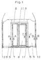
- the fire protection wall as shown in Figure 1 is arranged as a combination of wall elements (9) and window frame elements (7) as well as door frame elements (11) with fireproof glass panels (8).
- the outside edges of the fire protection wall are connected by wall connection means (13) to the walls of a rail vehicle compartment.
- sealing strips of intumescent material (6) are provided in the gap between the wall element (9) and the frame element (7).
- an elastic sealing ribbon (2) is provided, held in a fixed position by the pressure plate (4).
- the elastic sealing ribbon (2) is a compressed elastic hollow profile.
- the pressure plate (4) is sealed with fire-inhibiting elastic sealing material (3) against the contact strips (10) and the frame elements (7).
- An angle profile (1) is provided of the front side extending with one side into the gap and one side covering the gap as well as part of the wall part.
- the frame element (7) and the doorframe profiles (11) are connected by covering strip (5) at the back side only.
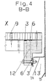
- Figure 4 shows wall connection means for connecting the fire protection wall to the compartment wall, comprising heat insulation element (12) and a sealing featuring intumescent material (6) on the exposed side and fire-inhibiting elastic sealing material (3) in an area sufficiently distant from the exposed side. Further, it is shown that the wall element (9) is attached to the compartment wall (15) by a bridge element (14) connected to the heat insulation element (12), again using an intumescent material (6) and the elastic sealing material (3) to protect this connection.
Landscapes
- Engineering & Computer Science (AREA)
- Life Sciences & Earth Sciences (AREA)
- Wood Science & Technology (AREA)
- Mechanical Engineering (AREA)
- Insulated Conductors (AREA)
- Building Environments (AREA)
- Special Wing (AREA)
- Combustion Methods Of Internal-Combustion Engines (AREA)
- Acyclic And Carbocyclic Compounds In Medicinal Compositions (AREA)
Abstract
Description
- The invention relates to a fire protection wall, having a front side expected to be exposed to a fire and an opposite back side, comprising a wall element having wall edges framed by a frame element, wherein a gap exists between the wall edge and the frame element. The invention further relates to a rail vehicle comprising said fire protection wall, and to a process for the manufacture of a fire protection wall. The invention also relates to a frame assembly, framed windows and doors that can be used to manufacture the fire protection wall.
- Fire protection is a very important issue in all compartments occupied by people, in particular in compartments where they cannot escape from a fire, such as in transport compartments. For example, in rail vehicles fireproof walls are required to protect the passengers or the driver of the train from a fire in an adjacent compartment. Such fire protection walls are not only required to be fire-resistant; they also have to prevent leakage of smoke into the adjacent compartment. Smoke poses a risk because it can spread the fire to the other compartments but, more importantly, smoke is dangerous because inhalation can lead to poisoning, suffocation and death. It is particularly difficult to make walls fireproof at the wall edges, where connections must be made to other structural components, for instance windows, doors or other walls.
- In
EP 0534932 B1 , a fireproof wall is described, wherein the gaps between the various structural components are provided with intumescent material. An intumescent material is a material that expands on exposure to heat. In said patent, the wall elements are, however, not provided with frame elements. Instead, the structural components, for example the windows, are connected directly, inside a U-shaped recess, to the wall parts with elastic material to seal the gaps. Underneath the elastic material, intumescent material is provided. The problem of this connection is that it does not sufficiently protect against leakage of smoke on exposure to a fire. It was found that, on exposure to fire, the entire wall significantly deforms, mainly by bulging out towards the fire. This deformation creates gaps, especially in those places where connections are made between different materials, for instance between a glass pane and a wall part. The prior art sealing is inadequate to accommodate the deformation and deformation forces occurring at high temperatures, especially since the material quickly loses its adhesive and elastic properties at such temperatures. There is, therefore, a need for an improved fireproof wall. - In
US 6327826 B1 , a doorframe assembly is described. However, this doorframe assembly does not provide long resistance against fire and leakage of smoke. - The invention also relates to a frame assembly for the manufacture of a fire protection wall according to
claim 1. Preferably, the frame assembly also comprises an extension covering the front wall part and an isolation element separating the elastic sealing and covering strip from the wall part. - Further, the invention relates to a framed window or door, comprising a window or door framed along the edges with a frame assembly according to the invention. All the improvement features of the fire protection wall described hereafter correspondingly apply to the frame assembly and the framed window and door, as well as to the process for the manufacture thereof as described hereafter.
- According to the invention, there is provided a fire protection wall, having a front side expected to be exposed to a fire and an opposite back side, comprising a wall element having wall edges framed by a frame element, wherein a gap exists between the wall edge and the frame element, in which gap there is provided along the wall edges an intumescent material at the front side of the fire protection wall and an elastic sealing material at a position nearer to the back side of the fire protection wall.
- In the fire protection wall according to the invention the wall element and frame element are preferably connected by a back connection element at the back side of the fire protection wall. The advantage of this is that, on deformation of the fire protection wall, the gap is forced to maintain a V shape for much longer, hence securing the sealing properties of the elastic sealing material for much longer. The back connection element is a covering strip connecting the wall element and frame element and covering the gap between the wall element and the frame element, providing even better and longer protection against leakage of smoke through the gap.
In a preferred embodiment, the back connection element is a strip extending from the frame element, preferably as integral part of the frame element. - Preferably, the wall element and the frame element are of a fire-resistant material. Optionally, the frame element or wall element can be provided with additional means known in the art to improve fire resistance thereof, for instance water-containing filling materials. It was found that the fire protection wall according to the invention is capable of accommodating deformation of the fire protection wall occurring when exposed to a fire and provides better protection against leakage of smoke through the gaps between connected structural components, "better" meaning for a longer time and/or at higher temperatures.
- It was found that, when the protection wall is exposed to a fire at its front side, it bulges towards the fire, causing the gap between the wall element and the frame element to become V-shaped. The elastic sealing material at a position near the back side of the fire protection wall seals the gap at its smaller end and, hence, can seal the opening gap for a longer time and, being more remote from the heat, also retains its elastic properties for a longer time and at higher temperatures. Preferably, the temperature at which the intumescent material starts to expand (hereinafter referred to as the expansion onset temperature) is lower than the temperature at which the elastic material loses its sealing function because of the heat (hereinafter also referred to as the "deformation temperature"). In that way, the intumescent material closes the gap before the elastic material loses its sealing function. It can also protect the elastic material from further loosing its sealing function and closes the gap to protect against leakage of smoke. The term "near" does not imply any particular position other than that the intumescent material is in front of the elastic material, nearer to where a fire is expected. In order to ensure that the intumescent material starts to expand at the desired temperature below the deformation temperature of the elastic sealing material, a heat bridge of heat-conducting material can be provided between the two sealing materials, causing both materials to be exposed to approximately equal temperatures.
- Elastic sealing materials are, preferably, fire-resistant as well. In principle, a wide variety of elastic sealing materials can be used, for example a fire-resistant rubber, preferably silicone rubber. In the fire protection wall according to the invention, the elastic sealing material is preferably a compressed elastic material. Suitable compressible elastic materials are, for example, foamed rubbers or hollow elastic profiles. The advantage of a compressed elastic material in the gap is that, on deformation of the fire protection wall and increase of the gap between the frame and the wall element, the elastic material follows the increase of the gap, providing a more secure sealing thereof.
- On exposure to a fire, the frame and the sealing materials heat up by direct contact to heat, but may also heat up indirectly by heat conduction via the wall element. Preferably, heat isolation is provided between the wall element and the components of the frame, in particular between the wall element and the elastic sealing material and preferably also between the wall element and the back connection element, wherein the back connection element is connected only to the heat isolation element and not directly to the wall part. The heat isolation element prevents heat flow from the wall element to the elastic sealing material and/or the back connection element, hence providing longer resistance against the fire and the leakage of smoke.
- In a further embodiment, the fire protection wall according to the invention comprises at the front side along the wall edge an angle profile with one side extending into the gap between the wall element and the frame element and with the other side covering the front side wall element and wherein the intumescent material is positioned between the wall edge and the angle profile. On exposure to temperatures above the expansion temperature of the intumescent material, the expanding intumescent material will push the angle profile away from the wall element, in this way closing the gap and protecting the elastic sealing material from the heat. In this way, the connection is able to accommodate very severe deformation of the wall without losing its smoke-excluding property. Preferably, further intumescent material is positioned between the angle profile and the frame element to prevent a gap forming between the angle profile and the frame element.
Instead of this, in another embodiment, the frame element comprises an extension strip at the front side along the frame length. - Preferably, the intumescent material is positioned in a recess in the frame element. This forces the intumescent material to expand in the direction of the gap instead of spreading sideways. If the sealing material is a compressed elastic material, the compressed elastic material is preferably retained and preferably pre-compressed by a pressure plate. The advantage is that the compressed elastic material is securely positioned in the gap, even when the wall deforms during exposure to fire, and expands in the direction of the gap.
- The above-described construction is particularly suitable for connecting a wall part to a window or a door. In a practical embodiment of the invention a window or a door is provided complete with the frame element all along the edges for mounting in an opening in a wall element using the construction according to the invention. The construction can also be applied for connecting the outer wall edges at the extremities of the fire protection wall to the compartment walls. However, in another embodiment, the fire protection wall comprises an outer wall edge and, along said edge, wall connection means, for connecting to another wall, comprising an isolation frame connected to the wall element and having, between the wall element and the isolation frame, an intumescent material positioned near the front side and an elastic sealing material near the back side of the fire protection wall. Preferably, the wall connection means comprises a bridge element along the length of the connection means to connect the isolation frame to the other wall with a gap between the fire protection wall and the other wall. This provides a further reduction of heat transfer from the fire protection wall to the compartment walls. Preferably, intumescent material is positioned. Preferably, the bridge element is heat-insulating and/or connected overheat/insulation material is provided to further reduce heat flow to the compartment wall. Between the isolation frame and the bridge element, intumescent material is positioned near the front side and elastic sealing material near the back side of the fire protection wall.
- In a preferred embodiment, the fire protection wall comprises a wall element having a wall edge, a frame element along the wall edge, an angle profile along the wall edges at the front side with one side extending in a gap between the wall edge and the frame element and with the other side covering the front side wall element, intumescent material positioned between the wall edge and the angle profile, a compressed elastic sealing ribbon in the gap near the back side, a covering strip covering the gap and connecting the wall element and frame element at the back side only and a heat isolation element separating the wall element from compressed elastic sealing ribbon and the back connection element.
- The fire protection wall as described above is designed for protecting against the threat of a fire at one side only. In many cases a threat exists on both sides of the fire protection wall. The invention hence also relates to a dual fire protection wall comprising two fire protection walls as described above with the front side facing outward. In another embodiment of the dual fire protection wall, the two fire protection walls are merged to one wall, for example with a structure essentially mirror symmetric with respect to a plan parallel plane through the elastic sealing.
- The invention further relates to a rail vehicle comprising a fire protection wall as described above.
- The invention further relates to a process for the manufacture of a fireproof wall, comprising providing a wall element comprising wall edges, framing the wall edges with a frame element leaving a gap between the wall edge and the frame element, providing along the wall edges an intumescent material at a position near the front side of the fire protection wall and providing along the wall edges an elastic sealing material near the back side of the fire protection wall.
- A further preferred process provides an extension along the frame edges at the front side covering the gap and part of the front side wall element and covering strip rigidly connecting wall element and frame element at the back side only, covering the gap along the wall edge.
- The fire protection wall of the present invention will now be described, by way of example only, with reference to the accompanying drawings, in which:
-
Figure 1 is a front view of a fire protection wall in a train compartment; -
Figure 2 is a cross-sectional view of the connection between a wall element and a frame element connecting to a window pane; -
Figure 3 is a cross-sectional view of the fire protection wall showing the connection of a wall element over a frame element to a door; and -
Figure 4 shows in cross-sectional view the connection between the outer edge of the fire protection wall to another wall. - Throughout this document, the expression "elastic sealing ribbon" is used to designate an elastic sealing ribbon, an elastic sealing or sealing profiles. The expression "elastic sealing material" is used to designate an elastic sealing material, an elastic sealant, an elastic material or a sealant. The wording "heat insulation element" can designate a heat insulation element or a heat insulation frame.
- The fire protection wall as shown in
Figure 1 is arranged as a combination of wall elements (9) and window frame elements (7) as well as door frame elements (11) with fireproof glass panels (8). The outside edges of the fire protection wall are connected by wall connection means (13) to the walls of a rail vehicle compartment. - As can be seen in
Figures 2 and 3 , on the side expected to be exposed to a fire (indicated by an X), sealing strips of intumescent material (6) are provided in the gap between the wall element (9) and the frame element (7). In the gap, sufficiently distant from the exposed side, an elastic sealing ribbon (2) is provided, held in a fixed position by the pressure plate (4). The elastic sealing ribbon (2) is a compressed elastic hollow profile. In addition, the pressure plate (4) is sealed with fire-inhibiting elastic sealing material (3) against the contact strips (10) and the frame elements (7). An angle profile (1) is provided of the front side extending with one side into the gap and one side covering the gap as well as part of the wall part. In order to stabilize and secure, in case of a fire, the position of the gaps to be bridged by the elastic sealing ribbon (2) and the elastic sealing material (3) up to the defined temperature, the frame element (7) and the doorframe profiles (11) are connected by covering strip (5) at the back side only. - Furthermore,
Figure 4 shows wall connection means for connecting the fire protection wall to the compartment wall, comprising heat insulation element (12) and a sealing featuring intumescent material (6) on the exposed side and fire-inhibiting elastic sealing material (3) in an area sufficiently distant from the exposed side. Further, it is shown that the wall element (9) is attached to the compartment wall (15) by a bridge element (14) connected to the heat insulation element (12), again using an intumescent material (6) and the elastic sealing material (3) to protect this connection. - In case of a fire, as soon as a defined temperature has been reached, the sealing of the gap between the angle profile (1) and the wall element (9) is achieved by the expansion of the intumescent material (6). In areas sufficiently distant from the exposed side, protection against the release of hot smoke gas is ensured by the arrangement of the elastic sealing ribbon (2) and fire-inhibiting elastic sealing material (3) as well as by fixing and securing the position of the gaps to be bridged by the elastic sealing ribbon (2) and the elastic sealing material (3) up to the defined temperature by covering strip (5).
Claims (16)
- Frame assembly for the manufacture of a fire protection wall comprising a frame element (7, 11), intumescent material (6) along the length of the frame element (7, 11) at a front side expected to be exposed to a fire and a compressed elastic sealing ribbon (2) nearer to the back side characterized in that it further comprises a covering strip (5) for connecting a wall element and the frame element (7, 11) at the back side only, the covering strip (5) is suitable for covering the gap between the wall element (9) and the frame element (7, 11).
- Framed window or door, comprising a window or door framed along the edges with a frame assembly according to claim 1.
- Fire protection wall, having a front side (X) expected to be exposed to a fire and an opposite back side, comprising a wall element (9) having wall edges framed by a frame element (7, 11), wherein a gap exists between the wall edge and the frame element (7,11), in which gap there is provided along the wall edges an intumescent material (6) at the front side (X) and elastic sealing material (3) at a position nearer to the back side of the fire protection wall characterized in that the wall element (9) and frame element (7, 11) are connected by a covering strip (5) at the back side of the fire protection wall, the covering strip (5) connecting the wall element (9) and frame element (7, 11) and covering the gap between the wall element (9) and the frame element (7, 11).
- Fire protection wall according to claim 3, wherein the elastic sealing material (3) is a compressed elastic sealing ribbon (2) positioned along the wall edges.
- Fire protection wall according to claim 3 or 4, wherein the covering strip (5) an an extension of the frame element (7, 11).
- Fire protection wall according to claims 3 or 4, wherein between the wall element (9) and the covering strip (5) a heat-isolation element (10) is provided and wherein the covering strip (5) is connected only to the heat-isolation element (10).
- Fire protection wall according to claims 4 to 6, wherein the heat-isolation element (10) is provided to separate the wall (9) element and the elastic sealing material (3).
- Fire protection wall according to any one of claims 3 to 7, wherein the frame element (7, 11) comprises, at the front side (X) along the length of the frame element (7, 11) an extension strip covering the front side wall element and the gap.
- Fire protection wall according to any one of claims 3 to 7, further comprising at the front side (X) along the wall edge an angle profile (1) with one side extending into the gap between the wall element (9) and the frame element (7, 11) and with the other side covering the front side wall element and wherein intumescent material (6) is positioned between the wall edge and the angle profile (1).
- Fire protection wall according to any one of claims 3 to 9, wherein the intumescent material (6) is positioned in a recess in the frame element (7, 11)
- Fire protection wall according to claim 4 and claim 10, wherein the compressed elastic sealing ribbon (2) is pre-compressed by a pressure plate (4).
- Fire protection wall according to any one of claims 3 to 11, comprising an outer wall edge and, along said edge, wall connection means (13), for connecting to another wall (15), comprising an isolation frame (12) connected to the wall element (9) and having, between the wall element (9) and the isolation frame (12), an intumescent material (6) positioned nearer to the front side (X) and an elastic sealing material (3) nearer to the back side of the fire protection wall.
- Fire protection wall according to any one of claim 12, wherein the wall connection means (13) comprises a bridge element (14) to connect the isolation frame (12) to the other wall (15) with a gap between the fire protection wall and the other wall.
- Fire protection wall according to any one of claim 13, wherein, between the isolation frame (6) and the bridge element (14), an intumescent material (6) is positioned near the front side (X) and an elastic sealing material (3) near the back side of the fire protection wall.
- Rail vehicle comprising a fire protection wall according to any one of claims 3 to 14.
- Process for manufacture of a fire protection wall comprising a front side (X) and a back side, the process comprising:- providing a wall element (9) comprising wall edges;- framing the wall edges with a frame element (7, 11) leaving a gap between the wall edge and the frame element (7, 11);- providing in said gap all along the wall edges an intumescent material (6) at the front side (X) of the fire protection wall; and- providing along the wall edges an elastic sealing material (3) nearer to the back side of the fire protection wall;- providing an extension strip to the front side (X) of the frame element (7, 11) covering the gap and part of the front side (X) of the wall element (9); and- providing a covering strip (5) connecting the wall element (9) and frame element (7, 11) and covering the gap between the wall element (9) and frame element (7, 11) for rigidly connecting wall element (9) and frame element (7, 11) at the back side only.
Priority Applications (1)
| Application Number | Priority Date | Filing Date | Title |
|---|---|---|---|
| PL04790223T PL1682394T3 (en) | 2003-10-10 | 2004-10-08 | Fire protection wall |
Applications Claiming Priority (2)
| Application Number | Priority Date | Filing Date | Title |
|---|---|---|---|
| GBGB0323795.5A GB0323795D0 (en) | 2003-10-10 | 2003-10-10 | Fire protection wall |
| PCT/EP2004/011286 WO2005039949A1 (en) | 2003-10-10 | 2004-10-08 | Fire protection wall |
Publications (2)
| Publication Number | Publication Date |
|---|---|
| EP1682394A1 EP1682394A1 (en) | 2006-07-26 |
| EP1682394B1 true EP1682394B1 (en) | 2011-03-02 |
Family
ID=29433697
Family Applications (1)
| Application Number | Title | Priority Date | Filing Date |
|---|---|---|---|
| EP04790223A Expired - Lifetime EP1682394B1 (en) | 2003-10-10 | 2004-10-08 | Fire protection wall |
Country Status (7)
| Country | Link |
|---|---|
| EP (1) | EP1682394B1 (en) |
| CN (1) | CN100537321C (en) |
| AT (1) | ATE500109T1 (en) |
| DE (1) | DE602004031653D1 (en) |
| GB (1) | GB0323795D0 (en) |
| PL (1) | PL1682394T3 (en) |
| WO (1) | WO2005039949A1 (en) |
Cited By (1)
| Publication number | Priority date | Publication date | Assignee | Title |
|---|---|---|---|---|
| DE102017111965A1 (en) | 2017-05-31 | 2018-12-06 | Bombardier Transportation Gmbh | Composite system, fire protection cabinet and means of transport comprising a fire protection cabinet |
Families Citing this family (1)
| Publication number | Priority date | Publication date | Assignee | Title |
|---|---|---|---|---|
| AT15254U1 (en) * | 2016-02-09 | 2017-04-15 | Manfred Teufl | TRANSITION TO ARRANGEMENT BETWEEN TWO RIDELY CONNECTED VEHICLES |
Family Cites Families (6)
| Publication number | Priority date | Publication date | Assignee | Title |
|---|---|---|---|---|
| AT382677B (en) * | 1984-01-27 | 1987-03-25 | Lindpointner Tore | SLIDING GATE, IN PARTICULAR FIRE PROTECTION SLIDING GATE |
| AT406853B (en) * | 1991-09-25 | 2000-10-25 | Ife Gmbh | PASSAGE OF A RAILWAY PASSENGER TRAIN |
| AT404707B (en) * | 1992-12-15 | 1999-02-25 | Wiener Metallwerk Gesmbh | DOOR ARRANGEMENT FOR A VEHICLE, IN PARTICULAR TRANSITION DOOR ON THE FRONT PANEL OF A RAILWAY WAGON |
| GB2309728B (en) * | 1996-02-01 | 1999-09-08 | Lorient Polyprod Ltd | Structural frame member |
| CN2259449Y (en) * | 1996-11-28 | 1997-08-13 | 南京福臻实业有限公司 | High-strength light fireproof structural slab and composite wall body and composite board |
| CN1076681C (en) * | 1997-01-17 | 2001-12-26 | 凯萨德工程公司 | Mat with integrally molded door |
-
2003
- 2003-10-10 GB GBGB0323795.5A patent/GB0323795D0/en not_active Ceased
-
2004
- 2004-10-08 AT AT04790223T patent/ATE500109T1/en active
- 2004-10-08 WO PCT/EP2004/011286 patent/WO2005039949A1/en not_active Ceased
- 2004-10-08 PL PL04790223T patent/PL1682394T3/en unknown
- 2004-10-08 DE DE602004031653T patent/DE602004031653D1/en not_active Expired - Lifetime
- 2004-10-08 EP EP04790223A patent/EP1682394B1/en not_active Expired - Lifetime
- 2004-10-08 CN CNB2004800355111A patent/CN100537321C/en not_active Expired - Fee Related
Cited By (1)
| Publication number | Priority date | Publication date | Assignee | Title |
|---|---|---|---|---|
| DE102017111965A1 (en) | 2017-05-31 | 2018-12-06 | Bombardier Transportation Gmbh | Composite system, fire protection cabinet and means of transport comprising a fire protection cabinet |
Also Published As
| Publication number | Publication date |
|---|---|
| EP1682394A1 (en) | 2006-07-26 |
| PL1682394T3 (en) | 2011-07-29 |
| WO2005039949A1 (en) | 2005-05-06 |
| CN100537321C (en) | 2009-09-09 |
| GB0323795D0 (en) | 2003-11-12 |
| CN1886289A (en) | 2006-12-27 |
| ATE500109T1 (en) | 2011-03-15 |
| DE602004031653D1 (en) | 2011-04-14 |
Similar Documents
| Publication | Publication Date | Title |
|---|---|---|
| AU726093B2 (en) | Structural frame member | |
| NO319863B1 (en) | Fire protection door or window | |
| HU212006B (en) | Fire-resistant glass partition | |
| JP2878136B2 (en) | Fire insulation sash | |
| CN112026806B (en) | Fireproof partition door structure | |
| RU129138U1 (en) | FIRE DOOR FOR RAIL VEHICLE | |
| CZ299987B6 (en) | Fire-inhibiting flat element comprising at least two transparent fire-resisting glass plates | |
| KR102619172B1 (en) | Double insulation fireproof glass door | |
| EP1687191B1 (en) | Fireproof sliding door assembly for a fire protection wall | |
| RU2392407C2 (en) | Elastomer sealing profile for threshold sealant | |
| EP1682394B1 (en) | Fire protection wall | |
| CN108049763A (en) | A kind of aluminium alloy fire proof seal window | |
| KR101764206B1 (en) | Hollow type Insulation high efficiency Window frame | |
| CN217129356U (en) | Novel sash frame structure of fire-resistant window | |
| CN212507979U (en) | Double-open smoke-proof fireproof door | |
| CN212507980U (en) | Single-opening smoke-proof fireproof door | |
| JPS6114384A (en) | Fire-proof glass inlay structure having pressure system acting on edge region of glass panel at time of fire | |
| US8316584B2 (en) | Fireproofing element for a door or window leaf | |
| CN212507998U (en) | Combined sealing strip for fireproof door and sealing structure thereof | |
| CN214532650U (en) | High-efficiency energy-saving combined aluminum alloy casement window | |
| JPH08151864A (en) | Fireproof glass plate mounting structure | |
| KR100591733B1 (en) | Strip tape mounting structure of fire door, frame member | |
| JP2024067885A (en) | Airtight material and fitting | |
| RU13908U1 (en) | FIREPROOF GLAZING DOOR OPENING | |
| FI117347B (en) | Fire protected with hinged construction |
Legal Events
| Date | Code | Title | Description |
|---|---|---|---|
| PUAI | Public reference made under article 153(3) epc to a published international application that has entered the european phase |
Free format text: ORIGINAL CODE: 0009012 |
|
| 17P | Request for examination filed |
Effective date: 20060407 |
|
| AK | Designated contracting states |
Kind code of ref document: A1 Designated state(s): AT BE BG CH CY CZ DE DK EE ES FI FR GB GR HU IE IT LI LU MC NL PL PT RO SE SI SK TR |
|
| 17Q | First examination report despatched |
Effective date: 20060914 |
|
| DAX | Request for extension of the european patent (deleted) | ||
| GRAP | Despatch of communication of intention to grant a patent |
Free format text: ORIGINAL CODE: EPIDOSNIGR1 |
|
| GRAS | Grant fee paid |
Free format text: ORIGINAL CODE: EPIDOSNIGR3 |
|
| GRAA | (expected) grant |
Free format text: ORIGINAL CODE: 0009210 |
|
| RAP1 | Party data changed (applicant data changed or rights of an application transferred) |
Owner name: BOMBARDIER TRANSPORTATION GMBH |
|
| AK | Designated contracting states |
Kind code of ref document: B1 Designated state(s): AT BE BG CH CY CZ DE DK EE ES FI FR GB GR HU IE IT LI LU MC NL PL PT RO SE SI SK TR |
|
| REG | Reference to a national code |
Ref country code: GB Ref legal event code: FG4D |
|
| REG | Reference to a national code |
Ref country code: CH Ref legal event code: EP |
|
| REG | Reference to a national code |
Ref country code: IE Ref legal event code: FG4D |
|
| REF | Corresponds to: |
Ref document number: 602004031653 Country of ref document: DE Date of ref document: 20110414 Kind code of ref document: P |
|
| REG | Reference to a national code |
Ref country code: DE Ref legal event code: R096 Ref document number: 602004031653 Country of ref document: DE Effective date: 20110414 |
|
| REG | Reference to a national code |
Ref country code: CH Ref legal event code: NV Representative=s name: ABREMA AGENCE BREVET ET MARQUES, GANGUILLET |
|
| REG | Reference to a national code |
Ref country code: NL Ref legal event code: T3 |
|
| PG25 | Lapsed in a contracting state [announced via postgrant information from national office to epo] |
Ref country code: ES Free format text: LAPSE BECAUSE OF FAILURE TO SUBMIT A TRANSLATION OF THE DESCRIPTION OR TO PAY THE FEE WITHIN THE PRESCRIBED TIME-LIMIT Effective date: 20110613 Ref country code: SE Free format text: LAPSE BECAUSE OF FAILURE TO SUBMIT A TRANSLATION OF THE DESCRIPTION OR TO PAY THE FEE WITHIN THE PRESCRIBED TIME-LIMIT Effective date: 20110302 Ref country code: GR Free format text: LAPSE BECAUSE OF FAILURE TO SUBMIT A TRANSLATION OF THE DESCRIPTION OR TO PAY THE FEE WITHIN THE PRESCRIBED TIME-LIMIT Effective date: 20110603 |
|
| REG | Reference to a national code |
Ref country code: PL Ref legal event code: T3 |
|
| PG25 | Lapsed in a contracting state [announced via postgrant information from national office to epo] |
Ref country code: SI Free format text: LAPSE BECAUSE OF FAILURE TO SUBMIT A TRANSLATION OF THE DESCRIPTION OR TO PAY THE FEE WITHIN THE PRESCRIBED TIME-LIMIT Effective date: 20110302 Ref country code: FI Free format text: LAPSE BECAUSE OF FAILURE TO SUBMIT A TRANSLATION OF THE DESCRIPTION OR TO PAY THE FEE WITHIN THE PRESCRIBED TIME-LIMIT Effective date: 20110302 Ref country code: BG Free format text: LAPSE BECAUSE OF FAILURE TO SUBMIT A TRANSLATION OF THE DESCRIPTION OR TO PAY THE FEE WITHIN THE PRESCRIBED TIME-LIMIT Effective date: 20110602 Ref country code: CY Free format text: LAPSE BECAUSE OF FAILURE TO SUBMIT A TRANSLATION OF THE DESCRIPTION OR TO PAY THE FEE WITHIN THE PRESCRIBED TIME-LIMIT Effective date: 20110302 |
|
| PG25 | Lapsed in a contracting state [announced via postgrant information from national office to epo] |
Ref country code: BE Free format text: LAPSE BECAUSE OF FAILURE TO SUBMIT A TRANSLATION OF THE DESCRIPTION OR TO PAY THE FEE WITHIN THE PRESCRIBED TIME-LIMIT Effective date: 20110302 |
|
| PG25 | Lapsed in a contracting state [announced via postgrant information from national office to epo] |
Ref country code: EE Free format text: LAPSE BECAUSE OF FAILURE TO SUBMIT A TRANSLATION OF THE DESCRIPTION OR TO PAY THE FEE WITHIN THE PRESCRIBED TIME-LIMIT Effective date: 20110302 Ref country code: PT Free format text: LAPSE BECAUSE OF FAILURE TO SUBMIT A TRANSLATION OF THE DESCRIPTION OR TO PAY THE FEE WITHIN THE PRESCRIBED TIME-LIMIT Effective date: 20110704 |
|
| PG25 | Lapsed in a contracting state [announced via postgrant information from national office to epo] |
Ref country code: RO Free format text: LAPSE BECAUSE OF FAILURE TO SUBMIT A TRANSLATION OF THE DESCRIPTION OR TO PAY THE FEE WITHIN THE PRESCRIBED TIME-LIMIT Effective date: 20110302 Ref country code: SK Free format text: LAPSE BECAUSE OF FAILURE TO SUBMIT A TRANSLATION OF THE DESCRIPTION OR TO PAY THE FEE WITHIN THE PRESCRIBED TIME-LIMIT Effective date: 20110302 Ref country code: CZ Free format text: LAPSE BECAUSE OF FAILURE TO SUBMIT A TRANSLATION OF THE DESCRIPTION OR TO PAY THE FEE WITHIN THE PRESCRIBED TIME-LIMIT Effective date: 20110302 |
|
| PLBE | No opposition filed within time limit |
Free format text: ORIGINAL CODE: 0009261 |
|
| STAA | Information on the status of an ep patent application or granted ep patent |
Free format text: STATUS: NO OPPOSITION FILED WITHIN TIME LIMIT |
|
| 26N | No opposition filed |
Effective date: 20111205 |
|
| PG25 | Lapsed in a contracting state [announced via postgrant information from national office to epo] |
Ref country code: DK Free format text: LAPSE BECAUSE OF FAILURE TO SUBMIT A TRANSLATION OF THE DESCRIPTION OR TO PAY THE FEE WITHIN THE PRESCRIBED TIME-LIMIT Effective date: 20110302 |
|
| REG | Reference to a national code |
Ref country code: DE Ref legal event code: R097 Ref document number: 602004031653 Country of ref document: DE Effective date: 20111205 |
|
| PG25 | Lapsed in a contracting state [announced via postgrant information from national office to epo] |
Ref country code: MC Free format text: LAPSE BECAUSE OF NON-PAYMENT OF DUE FEES Effective date: 20111031 |
|
| REG | Reference to a national code |
Ref country code: IE Ref legal event code: MM4A |
|
| PG25 | Lapsed in a contracting state [announced via postgrant information from national office to epo] |
Ref country code: IE Free format text: LAPSE BECAUSE OF NON-PAYMENT OF DUE FEES Effective date: 20111008 |
|
| PG25 | Lapsed in a contracting state [announced via postgrant information from national office to epo] |
Ref country code: LU Free format text: LAPSE BECAUSE OF NON-PAYMENT OF DUE FEES Effective date: 20111008 |
|
| PG25 | Lapsed in a contracting state [announced via postgrant information from national office to epo] |
Ref country code: TR Free format text: LAPSE BECAUSE OF FAILURE TO SUBMIT A TRANSLATION OF THE DESCRIPTION OR TO PAY THE FEE WITHIN THE PRESCRIBED TIME-LIMIT Effective date: 20110302 |
|
| PG25 | Lapsed in a contracting state [announced via postgrant information from national office to epo] |
Ref country code: HU Free format text: LAPSE BECAUSE OF FAILURE TO SUBMIT A TRANSLATION OF THE DESCRIPTION OR TO PAY THE FEE WITHIN THE PRESCRIBED TIME-LIMIT Effective date: 20110302 |
|
| REG | Reference to a national code |
Ref country code: FR Ref legal event code: PLFP Year of fee payment: 12 |
|
| REG | Reference to a national code |
Ref country code: FR Ref legal event code: PLFP Year of fee payment: 13 |
|
| REG | Reference to a national code |
Ref country code: FR Ref legal event code: PLFP Year of fee payment: 14 |
|
| REG | Reference to a national code |
Ref country code: FR Ref legal event code: PLFP Year of fee payment: 15 |
|
| REG | Reference to a national code |
Ref country code: CH Ref legal event code: PFUS Owner name: BOMBARDIER TRANSPORTATION GMBH, DE Free format text: FORMER OWNER: BOMBARDIER TRANSPORTATION GMBH, DE |
|
| PGFP | Annual fee paid to national office [announced via postgrant information from national office to epo] |
Ref country code: PL Payment date: 20200925 Year of fee payment: 17 |
|
| PGFP | Annual fee paid to national office [announced via postgrant information from national office to epo] |
Ref country code: NL Payment date: 20201028 Year of fee payment: 17 |
|
| PGFP | Annual fee paid to national office [announced via postgrant information from national office to epo] |
Ref country code: DE Payment date: 20201022 Year of fee payment: 17 Ref country code: IT Payment date: 20201026 Year of fee payment: 17 Ref country code: GB Payment date: 20201022 Year of fee payment: 17 Ref country code: FR Payment date: 20201021 Year of fee payment: 17 Ref country code: AT Payment date: 20201022 Year of fee payment: 17 Ref country code: CH Payment date: 20201021 Year of fee payment: 17 |
|
| REG | Reference to a national code |
Ref country code: DE Ref legal event code: R119 Ref document number: 602004031653 Country of ref document: DE |
|
| REG | Reference to a national code |
Ref country code: CH Ref legal event code: PL |
|
| REG | Reference to a national code |
Ref country code: NL Ref legal event code: MM Effective date: 20211101 |
|
| REG | Reference to a national code |
Ref country code: AT Ref legal event code: MM01 Ref document number: 500109 Country of ref document: AT Kind code of ref document: T Effective date: 20211008 |
|
| GBPC | Gb: european patent ceased through non-payment of renewal fee |
Effective date: 20211008 |
|
| PG25 | Lapsed in a contracting state [announced via postgrant information from national office to epo] |
Ref country code: NL Free format text: LAPSE BECAUSE OF NON-PAYMENT OF DUE FEES Effective date: 20211101 Ref country code: GB Free format text: LAPSE BECAUSE OF NON-PAYMENT OF DUE FEES Effective date: 20211008 Ref country code: DE Free format text: LAPSE BECAUSE OF NON-PAYMENT OF DUE FEES Effective date: 20220503 |
|
| PG25 | Lapsed in a contracting state [announced via postgrant information from national office to epo] |
Ref country code: LI Free format text: LAPSE BECAUSE OF NON-PAYMENT OF DUE FEES Effective date: 20211031 Ref country code: CH Free format text: LAPSE BECAUSE OF NON-PAYMENT OF DUE FEES Effective date: 20211031 Ref country code: AT Free format text: LAPSE BECAUSE OF NON-PAYMENT OF DUE FEES Effective date: 20211008 |
|
| PG25 | Lapsed in a contracting state [announced via postgrant information from national office to epo] |
Ref country code: FR Free format text: LAPSE BECAUSE OF NON-PAYMENT OF DUE FEES Effective date: 20211031 |
|
| PG25 | Lapsed in a contracting state [announced via postgrant information from national office to epo] |
Ref country code: IT Free format text: LAPSE BECAUSE OF NON-PAYMENT OF DUE FEES Effective date: 20211008 |
|
| PG25 | Lapsed in a contracting state [announced via postgrant information from national office to epo] |
Ref country code: PL Free format text: LAPSE BECAUSE OF NON-PAYMENT OF DUE FEES Effective date: 20211008 |