EP1683659B1 - Hitch for tow vehicles - Google Patents
Hitch for tow vehicles Download PDFInfo
- Publication number
- EP1683659B1 EP1683659B1 EP06000665A EP06000665A EP1683659B1 EP 1683659 B1 EP1683659 B1 EP 1683659B1 EP 06000665 A EP06000665 A EP 06000665A EP 06000665 A EP06000665 A EP 06000665A EP 1683659 B1 EP1683659 B1 EP 1683659B1
- Authority
- EP
- European Patent Office
- Prior art keywords
- carrier plate
- coupling
- hitch
- guide cheeks
- guide
- Prior art date
- Legal status (The legal status is an assumption and is not a legal conclusion. Google has not performed a legal analysis and makes no representation as to the accuracy of the status listed.)
- Expired - Lifetime
Links
Images

Classifications
-
- B—PERFORMING OPERATIONS; TRANSPORTING
- B60—VEHICLES IN GENERAL
- B60D—VEHICLE CONNECTIONS
- B60D1/00—Traction couplings; Hitches; Draw-gear; Towing devices
- B60D1/58—Auxiliary devices
- B60D1/583—Holding-down means, e.g. holding-down retainers
-
- B—PERFORMING OPERATIONS; TRANSPORTING
- B60—VEHICLES IN GENERAL
- B60D—VEHICLE CONNECTIONS
- B60D1/00—Traction couplings; Hitches; Draw-gear; Towing devices
- B60D1/01—Traction couplings or hitches characterised by their type
- B60D1/06—Ball-and-socket hitches
-
- B—PERFORMING OPERATIONS; TRANSPORTING
- B60—VEHICLES IN GENERAL
- B60D—VEHICLE CONNECTIONS
- B60D1/00—Traction couplings; Hitches; Draw-gear; Towing devices
- B60D1/01—Traction couplings or hitches characterised by their type
- B60D1/07—Multi-hitch devices, i.e. comprising several hitches of the same or of a different type; Hitch-adaptors, i.e. for converting hitches from one type to another
-
- B—PERFORMING OPERATIONS; TRANSPORTING
- B60—VEHICLES IN GENERAL
- B60D—VEHICLE CONNECTIONS
- B60D1/00—Traction couplings; Hitches; Draw-gear; Towing devices
- B60D1/24—Traction couplings; Hitches; Draw-gear; Towing devices characterised by arrangements for particular functions
- B60D1/42—Traction couplings; Hitches; Draw-gear; Towing devices characterised by arrangements for particular functions for being adjustable
- B60D1/46—Traction couplings; Hitches; Draw-gear; Towing devices characterised by arrangements for particular functions for being adjustable vertically
Definitions
- the invention relates to a hitch for tow vehicles, in particular agricultural tractors, comprising two guide cheeks attached to the vehicle with lateral spacing for a height-adjustable drawbar coupling and a horizontal carrier plate held detachably on the lower end area of the guide cheeks for a coupling element to provide a connection to an attached tool.
- the carrier plate with a coupling element arranged thereon can be replaced with a carrier plate with a different coupling element.
- the known hitch must therefore have a carrier plate with one of these coupling elements for each coupling element design which may be required.
- the drawbar coupling must be fitted with a carrier plate carrying the coupling element required.
- the object of the invention is to enlarge the area of application of a hitch of the type described initially.
- This object is achieved by providing on the carrier plate of two different coupling elements, the carrier plate being arranged to be fixed on the guide cheeks in two alternative attachment positions, so that by appropriate choice of the attachment position of the carrier plate either coupling element can be brought selectively into an active coupling position.
- a tractor equipped in this way thus constantly carries two designs of coupling elements, the carrier plate being selected from the existing stock of carrier plates according to the probable requirements before the start of travel. In many cases this helps avoid time losses which could occur because of incorrect coupling elements.
- three of these are required where on the first carrier plate a “clevis pin” coupling and “tow ball” are provided, on the second carrier plate a “clevis pin” coupling and “pintel pin” coupling are provided, and on the third carrier plate a "pintel pin” coupling and "tow ball” are provided. Since in most areas of application normally only two of the said coupling element designs will be used, the number of carrier plates required can be restricted to two. These can be selected so that the coupling element design mainly used in the current area of the application is present on each carrier plate.
- the carrier plate in its side areas can be connected with the guide cheeks via socket pins extending in the vehicle longitudinal direction, with its side areas in form fitting contact with the guide cheeks in the vehicle longitudinal direction. Forces in the vehicle longitudinal direction occurring in use are therefore not transferred via the socket pins but from the carrier plate directly to the guide cheeks via the form fitting contact. These socket pins are subjected merely to the far lower top-mount forces of the working tool.
- the side areas of the carrier plate can be designed in a fork-like configuration to form shackles which surround the guide cheeks at the front and rear and limit the maximum mobility of the carrier plate in the vehicle longitudinal direction to a low amount. This makes the coupling device insensitive to impacts and practically wear-free.
- the side areas of the carrier plate holding the socket pins lie above a centre area of the carrier plate which carries the coupling elements.
- the guide cheeks can end at a greater height above ground (i.e. the guide checks can be shorter vertically) so that the ground clearance in this area is enlarged. This effect can easily be achieved if the side areas of the carrier plate are angled upwards.
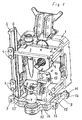
- the figures show the back of a tractor with a hitch.
- the rear wall of the rear axle marked 1 can be seen, from which protrudes centrally a power take-off shaft 2 serving to drive attached working tools and covered by a protective plate 3.
- a power take-off shaft 2 serving to drive attached working tools and covered by a protective plate 3.
- the guide cheeks 5 have opposing guide grooves 6 for a height-adjustable drawbar coupling not shown.
- front eyes 7 and rear eyes 8 with through bores running in the longitudinal direction of the tractor.
- the through bores serve to hold two socket pins 9 with which is held on to the guide cheeks 5 a carrier plate 10 for two coupling elements 12 and 13.
- the carrier plate 10 has in the centre a flat horizontal area 14 on which are arranged the coupling elements 12, 13, and right and left side areas 15 which are angled up at an angle of around 30° and designed as forks forming front and rear shackles 16 through which the socket pins 9 extend and are held in position by linch pins 11.
- the angled sides 15 cause the longitudinal bores in the shackles 16 to lie in a plane above the centre area 14 of the carrier plate, so that the guide cheeks 5 can be designed correspondingly shorter.
- the shackles 16 have the greatest possible distance apart in order to keep low their loads from traction forces acting oblique to the vehicle longitudinal direction
- the coupling elements are a ball coupling 12 and a clevis type coupling 13 which lie behind each other in the vehicle longitudinal centre plane marked by the power take-off shaft 2.
- the ball coupling 12 in relation to the vehicle is behind the clevis coupling 13 and hence in a position in which a working tool can be attached.
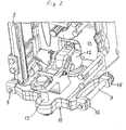
- the shackles 16 surround the eyes 7, 8 of the guide cheeks front and rear with a slight play whereby the carrier plate 10 is connected form-fit with the guide cheeks 5 in the vehicle longitudinal direction. Furthermore the shackles 16 are arranged symmetrical to the coupling elements 12, 13 so that after removal of the socket pins 9, by simple rotation of the carrier plate 10 and reinsertion of the socket pins 9, the other coupling element - in this case the clevis pin 13 - can be brought into the coupling position as shown in Fig. 2 .
- Fig. 3 shows a carrier plate 10 on which is attached a clevis pin coupling 13 and a pintel pin type coupling 17. Similarly a carrier plate 10 can be fitted with a ball coupling 12 and a pintle pin coupling 17. Evidently also other types of coupling element can be used without departing from the scope of the invention.
Landscapes
- Engineering & Computer Science (AREA)
- Transportation (AREA)
- Mechanical Engineering (AREA)
- Agricultural Machines (AREA)
- Medicines Containing Plant Substances (AREA)
- Fuel Cell (AREA)
- Agricultural Chemicals And Associated Chemicals (AREA)
Abstract
Description
- The invention relates to a hitch for tow vehicles, in particular agricultural tractors, comprising two guide cheeks attached to the vehicle with lateral spacing for a height-adjustable drawbar coupling and a horizontal carrier plate held detachably on the lower end area of the guide cheeks for a coupling element to provide a connection to an attached tool.
- For connection of a towed working tool with an agricultural tractor, coupling elements in various designs are available, known under the terms "tow ball", "pintel pin" and "clevis pin" coupling. Usually not all these designs are used on a particular agricultural tractor, but depending on the main areas of use only one or two. Thus for example in Germany alternate use of a tow ball with a clevis pin is normal, whereas in France mainly a clevis pin and a pintel pin are used. A hitch which facilitates the change from one design to the other is disclosed in
DE 101 18 862 C1 . The carrier plate here can be inserted detachably in opposing horizontal guide grooves of the guide cheeks and locked in relation to these by vertical socket pins. After removing the socket pins and releasing further means for play-free fixing of the carrier plate, the carrier plate with a coupling element arranged thereon can be replaced with a carrier plate with a different coupling element. The known hitch must therefore have a carrier plate with one of these coupling elements for each coupling element design which may be required. For a particular use therefore the drawbar coupling must be fitted with a carrier plate carrying the coupling element required. This however brings problems if the tractor is to be used for successive towing of working tools with different coupling designs and the tools are changed at locations other than where the carrier plate with the required coupling element is stored. In particular this is often the case for vehicles of contract hire companies covering a large territory. - The object of the invention is to enlarge the area of application of a hitch of the type described initially.
- This object is achieved by providing on the carrier plate of two different coupling elements, the carrier plate being arranged to be fixed on the guide cheeks in two alternative attachment positions, so that by appropriate choice of the attachment position of the carrier plate either coupling element can be brought selectively into an active coupling position.
- A tractor equipped in this way thus constantly carries two designs of coupling elements, the carrier plate being selected from the existing stock of carrier plates according to the probable requirements before the start of travel. In many cases this helps avoid time losses which could occur because of incorrect coupling elements. To accommodate the known designs of coupling elements in the proposed manner on the carrier plates, three of these are required where on the first carrier plate a "clevis pin" coupling and "tow ball" are provided, on the second carrier plate a "clevis pin" coupling and "pintel pin" coupling are provided, and on the third carrier plate a "pintel pin" coupling and "tow ball" are provided. Since in most areas of application normally only two of the said coupling element designs will be used, the number of carrier plates required can be restricted to two. These can be selected so that the coupling element design mainly used in the current area of the application is present on each carrier plate.
- To achieve a favourable transfer of the forces occurring from towing into the guide cheeks, the carrier plate in its side areas can be connected with the guide cheeks via socket pins extending in the vehicle longitudinal direction, with its side areas in form fitting contact with the guide cheeks in the vehicle longitudinal direction. Forces in the vehicle longitudinal direction occurring in use are therefore not transferred via the socket pins but from the carrier plate directly to the guide cheeks via the form fitting contact. These socket pins are subjected merely to the far lower top-mount forces of the working tool. Further refined, the side areas of the carrier plate can be designed in a fork-like configuration to form shackles which surround the guide cheeks at the front and rear and limit the maximum mobility of the carrier plate in the vehicle longitudinal direction to a low amount. This makes the coupling device insensitive to impacts and practically wear-free.
- In a further configuration of the invention the side areas of the carrier plate holding the socket pins lie above a centre area of the carrier plate which carries the coupling elements. For a prespecified height of the carrier plate above ground, the guide cheeks can end at a greater height above ground (i.e. the guide checks can be shorter vertically) so that the ground clearance in this area is enlarged. This effect can easily be achieved if the side areas of the carrier plate are angled upwards.
- The invention is now described in more detail below with reference to drawings of a hitch. These show:
- Fig. 1
- a hitch with a carrier plate for a ball coupling and a swivel drawbar, where the tow ball is in the working position,
- Fig. 2
- the hitch according to
Fig. 1 , where the clevis pin is in the working position, and - Fig. 3
- a hitch with a carrier plate for a pintel pin and a clevis pin, where the pintel pin is in the working position.
- The figures show the back of a tractor with a hitch. The rear wall of the rear axle marked 1 can be seen, from which protrudes centrally a power take-off shaft 2 serving to drive attached working tools and covered by a
protective plate 3. On both sides of the power take-off shaft 2, attached to the rear wall 1 by means ofbolts 4 are twovertical guide cheeks 5 of the hitch, of which the right-hand one viewed in the vehicle longitudinal direction is not shown for greater clarity. Theguide cheeks 5 have opposing guide grooves 6 for a height-adjustable drawbar coupling not shown. - In the lower end area on the
guide cheeks 5 are formed front eyes 7 andrear eyes 8 with through bores running in the longitudinal direction of the tractor. The through bores serve to hold twosocket pins 9 with which is held on to the guide cheeks 5 acarrier plate 10 for twocoupling elements carrier plate 10 has in the centre a flathorizontal area 14 on which are arranged thecoupling elements left side areas 15 which are angled up at an angle of around 30° and designed as forks forming front andrear shackles 16 through which thesocket pins 9 extend and are held in position bylinch pins 11. Theangled sides 15 cause the longitudinal bores in theshackles 16 to lie in a plane above thecentre area 14 of the carrier plate, so that theguide cheeks 5 can be designed correspondingly shorter. Theshackles 16 have the greatest possible distance apart in order to keep low their loads from traction forces acting oblique to the vehicle longitudinal direction - The coupling elements, known in themselves, are a
ball coupling 12 and aclevis type coupling 13 which lie behind each other in the vehicle longitudinal centre plane marked by the power take-off shaft 2. InFig. 1 theball coupling 12 in relation to the vehicle is behind theclevis coupling 13 and hence in a position in which a working tool can be attached. - The
shackles 16 surround theeyes 7, 8 of the guide cheeks front and rear with a slight play whereby thecarrier plate 10 is connected form-fit with theguide cheeks 5 in the vehicle longitudinal direction. Furthermore theshackles 16 are arranged symmetrical to thecoupling elements socket pins 9, by simple rotation of thecarrier plate 10 and reinsertion of thesocket pins 9, the other coupling element - in this case the clevis pin 13 - can be brought into the coupling position as shown inFig. 2 . -
Fig. 3 shows acarrier plate 10 on which is attached aclevis pin coupling 13 and a pintelpin type coupling 17. Similarly acarrier plate 10 can be fitted with aball coupling 12 and apintle pin coupling 17. Evidently also other types of coupling element can be used without departing from the scope of the invention.
Claims (6)
- A hitch for tow vehicles, in particular agricultural tractors, comprising two guide cheeks (5) attached to the vehicle with lateral spacing for a height-adjustable drawbar coupling, and a horizontal carrier plate (10) held detachably on the lower end area of the guide cheeks for a coupling element creating the connection with an attached working tool, characterised in that arranged on the carrier plate (10) are two different coupling elements (12, 13; 12, 17; 13, 17) and that the carrier plate (10) can be fixed on the guide cheeks (5) in two alternative attachment positions, so that by appropriate choice of the attachment position of the carrier plate (10) either coupling element can be brought selectively into an active coupling position.
- A hitch according to Claim 1, characterised in that side areas (15) of the carrier plate (10) are each attached to on respective guide cheek (5) via a socket pin (9) extending in the vehicle longitudinal direction.
- A hitch according to Claim 2, characterised in that the side areas of the carrier plate (10) are established as a form-fit on the guide cheeks (5) in the vehicle longitudinal direction.
- A hitch according to Claim 3, characterised in that each side area (15) of the carrier plate (10) is designed as forks forming shackles (16) which surround the associated guide cheek (5) at the front and back.
- A hitch according to one or more of Claims 1 to 4, characterised in that the side areas (15) of the carrier plate (10) holding the socket pins (9) lie above a centre area (14) of the carrier plate which carries the coupling elements (12, 13; 12, 17; 13, 17).
- A hitch according to Claim 5, characterised in that the side areas (15) of the carrier plate (10) are angled upwards.
Applications Claiming Priority (1)
| Application Number | Priority Date | Filing Date | Title |
|---|---|---|---|
| GB0501498A GB2422285A (en) | 2005-01-25 | 2005-01-25 | Interchangeable hitch for agricultural vehicles |
Publications (2)
| Publication Number | Publication Date |
|---|---|
| EP1683659A1 EP1683659A1 (en) | 2006-07-26 |
| EP1683659B1 true EP1683659B1 (en) | 2008-03-05 |
Family
ID=34259625
Family Applications (1)
| Application Number | Title | Priority Date | Filing Date |
|---|---|---|---|
| EP06000665A Expired - Lifetime EP1683659B1 (en) | 2005-01-25 | 2006-01-13 | Hitch for tow vehicles |
Country Status (4)
| Country | Link |
|---|---|
| EP (1) | EP1683659B1 (en) |
| AT (1) | ATE388029T1 (en) |
| DE (1) | DE602006000600T2 (en) |
| GB (1) | GB2422285A (en) |
Cited By (1)
| Publication number | Priority date | Publication date | Assignee | Title |
|---|---|---|---|---|
| EP2527170A1 (en) | 2011-05-26 | 2012-11-28 | Rheinmetall MAN Military Vehicles GmbH | Height-adjustable trailer coupling, in particular for commercial vehicles |
Families Citing this family (5)
| Publication number | Priority date | Publication date | Assignee | Title |
|---|---|---|---|---|
| GB2440710B (en) * | 2006-08-09 | 2010-07-28 | Agco Gmbh | Trailer coupling for tractive vehicles,in particular agricultural tractors |
| EP2062473A1 (en) * | 2007-11-23 | 2009-05-27 | ARIES S.r.l. | Tow assembly for agricultural machines |
| ATE513699T1 (en) * | 2008-04-03 | 2011-07-15 | Deere & Co | ARRANGEMENT FOR THE HEIGHT-ADJUSTABLE ATTACHMENT OF A TOWING COUPLING ON A TOWING VEHICLE |
| US8430419B2 (en) | 2010-02-18 | 2013-04-30 | Ian Garth | Vehicle coupling device |
| DE102011053861B3 (en) * | 2011-09-22 | 2013-02-21 | Gkn Walterscheid Gmbh | coupling adapter |
Family Cites Families (4)
| Publication number | Priority date | Publication date | Assignee | Title |
|---|---|---|---|---|
| US3922006A (en) * | 1974-10-15 | 1975-11-25 | Alfred Richard Borges | Selectable and height adjustable hitch |
| US5725229A (en) * | 1996-08-29 | 1998-03-10 | Mcwethy; Wesley I. | Tow hitch apparatus |
| DE10118862C1 (en) * | 2001-04-18 | 2002-07-25 | Hans Sauermann | Trailer coupling, for agricultural haulage work, has plate able to be pushed into and removed from guide grooves of cheek plates and lockable there by insertion bolt |
| DE10304978A1 (en) * | 2003-02-07 | 2004-08-19 | Deere & Company, Moline | Trailer hitch for an agricultural or industrial work vehicle |
-
2005
- 2005-01-25 GB GB0501498A patent/GB2422285A/en not_active Withdrawn
-
2006
- 2006-01-13 AT AT06000665T patent/ATE388029T1/en not_active IP Right Cessation
- 2006-01-13 DE DE602006000600T patent/DE602006000600T2/en not_active Expired - Lifetime
- 2006-01-13 EP EP06000665A patent/EP1683659B1/en not_active Expired - Lifetime
Cited By (2)
| Publication number | Priority date | Publication date | Assignee | Title |
|---|---|---|---|---|
| EP2527170A1 (en) | 2011-05-26 | 2012-11-28 | Rheinmetall MAN Military Vehicles GmbH | Height-adjustable trailer coupling, in particular for commercial vehicles |
| EP2527169A1 (en) | 2011-05-26 | 2012-11-28 | Rheinmetall MAN Military Vehicles GmbH | Height-adjustable trailer coupling, in particular for commercial vehicles |
Also Published As
| Publication number | Publication date |
|---|---|
| ATE388029T1 (en) | 2008-03-15 |
| GB0501498D0 (en) | 2005-03-02 |
| DE602006000600T2 (en) | 2009-04-02 |
| GB2422285A (en) | 2006-07-26 |
| DE602006000600D1 (en) | 2008-04-17 |
| EP1683659A1 (en) | 2006-07-26 |
Similar Documents
| Publication | Publication Date | Title |
|---|---|---|
| EP2654394B1 (en) | Tractor rear hitch | |
| CA2197798C (en) | Swivel hitch adaptable for use with either a tractor drawbar or two-point hitch | |
| US20160081261A1 (en) | Soil Cultivation Implement for Attachment to a Towing Vehicle | |
| US8596665B2 (en) | Trailer coupling | |
| EP2192026A1 (en) | Agricultural traction engine | |
| EP1683659B1 (en) | Hitch for tow vehicles | |
| US20070176395A1 (en) | Slidable fifth-wheel hitch | |
| EP1886845B3 (en) | Trailer coupling for tractive vehicles, in particular agricultural tractors | |
| US6749213B2 (en) | Drawbar support assembly | |
| EP3996978B1 (en) | Adapter system for a semi-trailer arrangement | |
| US7478823B2 (en) | Drawbar clevis assembly | |
| US6766867B1 (en) | Hitch assembly with sway block support | |
| US9381805B2 (en) | Tractor | |
| EP2820932B1 (en) | Trailer coupling | |
| DE202018000854U1 (en) | Functional drive for attachment to off-road vehicles | |
| EP2172092B1 (en) | Soil cultivation device | |
| EP2874483B1 (en) | Hitch device between agricultural implement/carriage and tractor | |
| EP0922380B1 (en) | Agiculural towing vehicle, and device for connecting trailers to agricultural towing vehicles | |
| EP3550953B1 (en) | An agricultural tractor having a component storage system | |
| US7040644B1 (en) | Hydraulic three point hitch | |
| EP2079598A2 (en) | Tractor hitches | |
| RO125413B1 (en) | Alternative coupling and traction system for disk harrows |
Legal Events
| Date | Code | Title | Description |
|---|---|---|---|
| PUAI | Public reference made under article 153(3) epc to a published international application that has entered the european phase |
Free format text: ORIGINAL CODE: 0009012 |
|
| AK | Designated contracting states |
Kind code of ref document: A1 Designated state(s): AT BE BG CH CY CZ DE DK EE ES FI FR GB GR HU IE IS IT LI LT LU LV MC NL PL PT RO SE SI SK TR |
|
| AX | Request for extension of the european patent |
Extension state: AL BA HR MK YU |
|
| 17P | Request for examination filed |
Effective date: 20070126 |
|
| 17Q | First examination report despatched |
Effective date: 20070226 |
|
| AKX | Designation fees paid |
Designated state(s): AT BE BG CH CY CZ DE DK EE ES FI FR GB GR HU IE IS IT LI LT LU LV MC NL PL PT RO SE SI SK TR |
|
| GRAP | Despatch of communication of intention to grant a patent |
Free format text: ORIGINAL CODE: EPIDOSNIGR1 |
|
| GRAS | Grant fee paid |
Free format text: ORIGINAL CODE: EPIDOSNIGR3 |
|
| GRAA | (expected) grant |
Free format text: ORIGINAL CODE: 0009210 |
|
| AK | Designated contracting states |
Kind code of ref document: B1 Designated state(s): AT BE BG CH CY CZ DE DK EE ES FI FR GB GR HU IE IS IT LI LT LU LV MC NL PL PT RO SE SI SK TR |
|
| REG | Reference to a national code |
Ref country code: GB Ref legal event code: FG4D |
|
| REG | Reference to a national code |
Ref country code: CH Ref legal event code: EP |
|
| REG | Reference to a national code |
Ref country code: IE Ref legal event code: FG4D |
|
| REF | Corresponds to: |
Ref document number: 602006000600 Country of ref document: DE Date of ref document: 20080417 Kind code of ref document: P |
|
| PG25 | Lapsed in a contracting state [announced via postgrant information from national office to epo] |
Ref country code: ES Free format text: LAPSE BECAUSE OF FAILURE TO SUBMIT A TRANSLATION OF THE DESCRIPTION OR TO PAY THE FEE WITHIN THE PRESCRIBED TIME-LIMIT Effective date: 20080616 Ref country code: FI Free format text: LAPSE BECAUSE OF FAILURE TO SUBMIT A TRANSLATION OF THE DESCRIPTION OR TO PAY THE FEE WITHIN THE PRESCRIBED TIME-LIMIT Effective date: 20080305 |
|
| PG25 | Lapsed in a contracting state [announced via postgrant information from national office to epo] |
Ref country code: AT Free format text: LAPSE BECAUSE OF FAILURE TO SUBMIT A TRANSLATION OF THE DESCRIPTION OR TO PAY THE FEE WITHIN THE PRESCRIBED TIME-LIMIT Effective date: 20080305 |
|
| NLV1 | Nl: lapsed or annulled due to failure to fulfill the requirements of art. 29p and 29m of the patents act | ||
| PG25 | Lapsed in a contracting state [announced via postgrant information from national office to epo] |
Ref country code: BE Free format text: LAPSE BECAUSE OF FAILURE TO SUBMIT A TRANSLATION OF THE DESCRIPTION OR TO PAY THE FEE WITHIN THE PRESCRIBED TIME-LIMIT Effective date: 20080305 Ref country code: PL Free format text: LAPSE BECAUSE OF FAILURE TO SUBMIT A TRANSLATION OF THE DESCRIPTION OR TO PAY THE FEE WITHIN THE PRESCRIBED TIME-LIMIT Effective date: 20080305 Ref country code: LV Free format text: LAPSE BECAUSE OF FAILURE TO SUBMIT A TRANSLATION OF THE DESCRIPTION OR TO PAY THE FEE WITHIN THE PRESCRIBED TIME-LIMIT Effective date: 20080305 Ref country code: SI Free format text: LAPSE BECAUSE OF FAILURE TO SUBMIT A TRANSLATION OF THE DESCRIPTION OR TO PAY THE FEE WITHIN THE PRESCRIBED TIME-LIMIT Effective date: 20080305 |
|
| PG25 | Lapsed in a contracting state [announced via postgrant information from national office to epo] |
Ref country code: CZ Free format text: LAPSE BECAUSE OF FAILURE TO SUBMIT A TRANSLATION OF THE DESCRIPTION OR TO PAY THE FEE WITHIN THE PRESCRIBED TIME-LIMIT Effective date: 20080305 Ref country code: NL Free format text: LAPSE BECAUSE OF FAILURE TO SUBMIT A TRANSLATION OF THE DESCRIPTION OR TO PAY THE FEE WITHIN THE PRESCRIBED TIME-LIMIT Effective date: 20080305 Ref country code: PT Free format text: LAPSE BECAUSE OF FAILURE TO SUBMIT A TRANSLATION OF THE DESCRIPTION OR TO PAY THE FEE WITHIN THE PRESCRIBED TIME-LIMIT Effective date: 20080805 Ref country code: SE Free format text: LAPSE BECAUSE OF FAILURE TO SUBMIT A TRANSLATION OF THE DESCRIPTION OR TO PAY THE FEE WITHIN THE PRESCRIBED TIME-LIMIT Effective date: 20080605 Ref country code: SK Free format text: LAPSE BECAUSE OF FAILURE TO SUBMIT A TRANSLATION OF THE DESCRIPTION OR TO PAY THE FEE WITHIN THE PRESCRIBED TIME-LIMIT Effective date: 20080305 |
|
| ET | Fr: translation filed | ||
| PG25 | Lapsed in a contracting state [announced via postgrant information from national office to epo] |
Ref country code: RO Free format text: LAPSE BECAUSE OF FAILURE TO SUBMIT A TRANSLATION OF THE DESCRIPTION OR TO PAY THE FEE WITHIN THE PRESCRIBED TIME-LIMIT Effective date: 20080305 |
|
| PG25 | Lapsed in a contracting state [announced via postgrant information from national office to epo] |
Ref country code: IS Free format text: LAPSE BECAUSE OF FAILURE TO SUBMIT A TRANSLATION OF THE DESCRIPTION OR TO PAY THE FEE WITHIN THE PRESCRIBED TIME-LIMIT Effective date: 20080705 |
|
| PLBE | No opposition filed within time limit |
Free format text: ORIGINAL CODE: 0009261 |
|
| STAA | Information on the status of an ep patent application or granted ep patent |
Free format text: STATUS: NO OPPOSITION FILED WITHIN TIME LIMIT |
|
| PG25 | Lapsed in a contracting state [announced via postgrant information from national office to epo] |
Ref country code: LT Free format text: LAPSE BECAUSE OF FAILURE TO SUBMIT A TRANSLATION OF THE DESCRIPTION OR TO PAY THE FEE WITHIN THE PRESCRIBED TIME-LIMIT Effective date: 20080305 Ref country code: DK Free format text: LAPSE BECAUSE OF FAILURE TO SUBMIT A TRANSLATION OF THE DESCRIPTION OR TO PAY THE FEE WITHIN THE PRESCRIBED TIME-LIMIT Effective date: 20080305 |
|
| 26N | No opposition filed |
Effective date: 20081208 |
|
| PG25 | Lapsed in a contracting state [announced via postgrant information from national office to epo] |
Ref country code: BG Free format text: LAPSE BECAUSE OF FAILURE TO SUBMIT A TRANSLATION OF THE DESCRIPTION OR TO PAY THE FEE WITHIN THE PRESCRIBED TIME-LIMIT Effective date: 20080605 Ref country code: EE Free format text: LAPSE BECAUSE OF FAILURE TO SUBMIT A TRANSLATION OF THE DESCRIPTION OR TO PAY THE FEE WITHIN THE PRESCRIBED TIME-LIMIT Effective date: 20080305 |
|
| PG25 | Lapsed in a contracting state [announced via postgrant information from national office to epo] |
Ref country code: MC Free format text: LAPSE BECAUSE OF NON-PAYMENT OF DUE FEES Effective date: 20090131 |
|
| PG25 | Lapsed in a contracting state [announced via postgrant information from national office to epo] |
Ref country code: CY Free format text: LAPSE BECAUSE OF FAILURE TO SUBMIT A TRANSLATION OF THE DESCRIPTION OR TO PAY THE FEE WITHIN THE PRESCRIBED TIME-LIMIT Effective date: 20080305 |
|
| PG25 | Lapsed in a contracting state [announced via postgrant information from national office to epo] |
Ref country code: IE Free format text: LAPSE BECAUSE OF NON-PAYMENT OF DUE FEES Effective date: 20090113 |
|
| REG | Reference to a national code |
Ref country code: CH Ref legal event code: PL |
|
| PG25 | Lapsed in a contracting state [announced via postgrant information from national office to epo] |
Ref country code: LI Free format text: LAPSE BECAUSE OF NON-PAYMENT OF DUE FEES Effective date: 20100131 Ref country code: GR Free format text: LAPSE BECAUSE OF FAILURE TO SUBMIT A TRANSLATION OF THE DESCRIPTION OR TO PAY THE FEE WITHIN THE PRESCRIBED TIME-LIMIT Effective date: 20080606 Ref country code: CH Free format text: LAPSE BECAUSE OF NON-PAYMENT OF DUE FEES Effective date: 20100131 |
|
| PG25 | Lapsed in a contracting state [announced via postgrant information from national office to epo] |
Ref country code: LU Free format text: LAPSE BECAUSE OF NON-PAYMENT OF DUE FEES Effective date: 20090113 |
|
| PG25 | Lapsed in a contracting state [announced via postgrant information from national office to epo] |
Ref country code: HU Free format text: LAPSE BECAUSE OF FAILURE TO SUBMIT A TRANSLATION OF THE DESCRIPTION OR TO PAY THE FEE WITHIN THE PRESCRIBED TIME-LIMIT Effective date: 20080906 |
|
| PG25 | Lapsed in a contracting state [announced via postgrant information from national office to epo] |
Ref country code: TR Free format text: LAPSE BECAUSE OF FAILURE TO SUBMIT A TRANSLATION OF THE DESCRIPTION OR TO PAY THE FEE WITHIN THE PRESCRIBED TIME-LIMIT Effective date: 20080305 |
|
| REG | Reference to a national code |
Ref country code: FR Ref legal event code: PLFP Year of fee payment: 11 |
|
| REG | Reference to a national code |
Ref country code: FR Ref legal event code: PLFP Year of fee payment: 12 |
|
| REG | Reference to a national code |
Ref country code: FR Ref legal event code: PLFP Year of fee payment: 13 |
|
| PGFP | Annual fee paid to national office [announced via postgrant information from national office to epo] |
Ref country code: GB Payment date: 20180119 Year of fee payment: 13 |
|
| PGFP | Annual fee paid to national office [announced via postgrant information from national office to epo] |
Ref country code: IT Payment date: 20180129 Year of fee payment: 13 |
|
| GBPC | Gb: european patent ceased through non-payment of renewal fee |
Effective date: 20190113 |
|
| PG25 | Lapsed in a contracting state [announced via postgrant information from national office to epo] |
Ref country code: GB Free format text: LAPSE BECAUSE OF NON-PAYMENT OF DUE FEES Effective date: 20190113 |
|
| PG25 | Lapsed in a contracting state [announced via postgrant information from national office to epo] |
Ref country code: IT Free format text: LAPSE BECAUSE OF NON-PAYMENT OF DUE FEES Effective date: 20190113 |
|
| PGFP | Annual fee paid to national office [announced via postgrant information from national office to epo] |
Ref country code: DE Payment date: 20220119 Year of fee payment: 17 |
|
| PGFP | Annual fee paid to national office [announced via postgrant information from national office to epo] |
Ref country code: FR Payment date: 20220119 Year of fee payment: 17 |
|
| REG | Reference to a national code |
Ref country code: DE Ref legal event code: R119 Ref document number: 602006000600 Country of ref document: DE |
|
| PG25 | Lapsed in a contracting state [announced via postgrant information from national office to epo] |
Ref country code: DE Free format text: LAPSE BECAUSE OF NON-PAYMENT OF DUE FEES Effective date: 20230801 |
|
| PG25 | Lapsed in a contracting state [announced via postgrant information from national office to epo] |
Ref country code: FR Free format text: LAPSE BECAUSE OF NON-PAYMENT OF DUE FEES Effective date: 20230131 |