EP1686011A1 - Trim assembly and method of manufacturing same - Google Patents
Trim assembly and method of manufacturing same Download PDFInfo
- Publication number
- EP1686011A1 EP1686011A1 EP06000552A EP06000552A EP1686011A1 EP 1686011 A1 EP1686011 A1 EP 1686011A1 EP 06000552 A EP06000552 A EP 06000552A EP 06000552 A EP06000552 A EP 06000552A EP 1686011 A1 EP1686011 A1 EP 1686011A1
- Authority
- EP
- European Patent Office
- Prior art keywords
- seal
- retaining mechanism
- trim
- trim panel
- door frame
- Prior art date
- Legal status (The legal status is an assumption and is not a legal conclusion. Google has not performed a legal analysis and makes no representation as to the accuracy of the status listed.)
- Withdrawn
Links
- 238000004519 manufacturing process Methods 0.000 title claims description 5
- 230000007246 mechanism Effects 0.000 claims abstract description 65
- 230000000717 retained effect Effects 0.000 claims abstract description 5
- 238000000034 method Methods 0.000 claims description 30
- 230000008569 process Effects 0.000 claims description 8
- 230000001070 adhesive effect Effects 0.000 claims description 7
- 239000000853 adhesive Substances 0.000 claims description 6
- 229920001296 polysiloxane Polymers 0.000 claims 1
- 239000000463 material Substances 0.000 description 8
- 230000000712 assembly Effects 0.000 description 2
- 238000000429 assembly Methods 0.000 description 2
- 239000000356 contaminant Substances 0.000 description 2
- 239000002184 metal Substances 0.000 description 2
- 238000012986 modification Methods 0.000 description 2
- 230000004048 modification Effects 0.000 description 2
- 239000003566 sealing material Substances 0.000 description 2
- XLYOFNOQVPJJNP-UHFFFAOYSA-N water Substances O XLYOFNOQVPJJNP-UHFFFAOYSA-N 0.000 description 2
- 239000011358 absorbing material Substances 0.000 description 1
- 230000009286 beneficial effect Effects 0.000 description 1
- 150000001875 compounds Chemical class 0.000 description 1
- 238000013461 design Methods 0.000 description 1
- 230000000694 effects Effects 0.000 description 1
- 229920002457 flexible plastic Polymers 0.000 description 1
- 239000003779 heat-resistant material Substances 0.000 description 1
- 238000001746 injection moulding Methods 0.000 description 1
- 238000009434 installation Methods 0.000 description 1
- 238000009413 insulation Methods 0.000 description 1
- 238000005259 measurement Methods 0.000 description 1
- 238000000465 moulding Methods 0.000 description 1
- 239000002985 plastic film Substances 0.000 description 1
- 229920001169 thermoplastic Polymers 0.000 description 1
- 239000004416 thermosoftening plastic Substances 0.000 description 1
- 238000012546 transfer Methods 0.000 description 1
- 230000032258 transport Effects 0.000 description 1
Images


Classifications
-
- B—PERFORMING OPERATIONS; TRANSPORTING
- B60—VEHICLES IN GENERAL
- B60R—VEHICLES, VEHICLE FITTINGS, OR VEHICLE PARTS, NOT OTHERWISE PROVIDED FOR
- B60R13/00—Elements for body-finishing, identifying, or decorating; Arrangements or adaptations for advertising purposes
- B60R13/08—Insulating elements, e.g. for sound insulation
- B60R13/0892—Insulating elements, e.g. for sound insulation for humidity insulation
-
- B—PERFORMING OPERATIONS; TRANSPORTING
- B60—VEHICLES IN GENERAL
- B60J—WINDOWS, WINDSCREENS, NON-FIXED ROOFS, DOORS, OR SIMILAR DEVICES FOR VEHICLES; REMOVABLE EXTERNAL PROTECTIVE COVERINGS SPECIALLY ADAPTED FOR VEHICLES
- B60J5/00—Doors
- B60J5/04—Doors arranged at the vehicle sides
- B60J5/0412—Lower door structure
- B60J5/0418—Water or sound barrier, e.g. watershields or seals between dry/wet compartment, sound or vibration dampers
-
- B—PERFORMING OPERATIONS; TRANSPORTING
- B60—VEHICLES IN GENERAL
- B60J—WINDOWS, WINDSCREENS, NON-FIXED ROOFS, DOORS, OR SIMILAR DEVICES FOR VEHICLES; REMOVABLE EXTERNAL PROTECTIVE COVERINGS SPECIALLY ADAPTED FOR VEHICLES
- B60J5/00—Doors
- B60J5/04—Doors arranged at the vehicle sides
- B60J5/0468—Fixation or mounting means specific for door components
-
- B—PERFORMING OPERATIONS; TRANSPORTING
- B60—VEHICLES IN GENERAL
- B60R—VEHICLES, VEHICLE FITTINGS, OR VEHICLE PARTS, NOT OTHERWISE PROVIDED FOR
- B60R13/00—Elements for body-finishing, identifying, or decorating; Arrangements or adaptations for advertising purposes
- B60R13/02—Internal Trim mouldings ; Internal Ledges; Wall liners for passenger compartments; Roof liners
- B60R13/0206—Arrangements of fasteners and clips specially adapted for attaching inner vehicle liners or mouldings
-
- B—PERFORMING OPERATIONS; TRANSPORTING
- B60—VEHICLES IN GENERAL
- B60R—VEHICLES, VEHICLE FITTINGS, OR VEHICLE PARTS, NOT OTHERWISE PROVIDED FOR
- B60R13/00—Elements for body-finishing, identifying, or decorating; Arrangements or adaptations for advertising purposes
- B60R13/02—Internal Trim mouldings ; Internal Ledges; Wall liners for passenger compartments; Roof liners
- B60R13/0237—Side or rear panels
- B60R13/0243—Doors
Definitions
- a trim assembly that is suitable for attachment to a door frame.
- the trim assembly comprises an interior portion, wherein the interior portion includes at least one retaining mechanism extending therefrom, and a seal having first and second sides, wherein the first side of the seal is adapted to bond to the door frame, and wherein the second side of the seal is capable of being removably retained by the interior portion of said trim panel by the at least one retaining mechanism.
- a method of the invention comprises the steps of forming a trim panel, wherein said trim panel includes at least one projection having a base, and forming a retaining mechanism on an end of said projection.
- Another method of the invention comprises the steps of forming a trim panel having at least retaining mechanism along a portion of said trim panel, positioning a seal along said trim panel, wherein said seal includes at least one aperture at a location on said seal that corresponds to a location of said at least one retaining mechanism, and fitting at least one of said at least one apertures of said seal over at least one of said corresponding at least one retaining mechanism.
- a door assembly 10 is generally shown according to an embodiment of the present invention.
- the door assembly 10 includes a first panel 12 and a second panel 14 and a seal 24 disposed therebetween.
- first panel 12 will be referred to herein as a door frame and the second panel 14 will be referred to herein as a trim panel.
- trim panel the first panel 12 and a trim panel 14 .
- the included illustrations of the disclosed method and apparatus may be applied in any environment having a first panel 12 and a second panel 14 wherein a seal is included, disposed, affixed, attached or the like therebetween.
- the door frame 12 and the trim panel 14 attached thereto are conventionally known, and, therefore the individual components are generally represented throughout the various drawings. In this manner, the drawings are not intended to encompass all possible types or embodiments of such frames and panels, and, therefore, only represent such panels to the extent that they form a door frame 12 and corresponding trim panel 14. Thus, one of ordinary skill in the art will recognize that the present invention may be practiced with a door frame and a trim panel that are not exactly represented in the provided drawings. Additionally, various seals are known in the art and have been previously developed to protect contaminants, such as water, from entering into the interior of the door assembly, and it is therefore desirable to shield the trim panel 14 and the vehicle interior from the contaminants.
- the seal 24 is formed of a semi-rigid or flexible plastic sheet that comprises a water impervious thermoplastic, heat resistant material.
- the particular material may be selected by one of ordinary skill in the art as commercially available types of material suitable for this purpose are known.
- other materials are known and used for seals, and may be adapted in accordance with the invention.
- One of ordinary skill in the art will recognize such materials when considering the present disclosure.
- the trim panel 14 includes an interior portion 16 and an exterior portion 18.
- the door frame 12 includes an interior portion 20 and an exterior portion 22.
- the interior portions 12,16 of the trim panel 14 and the door frame 12 are arranged in a facing relationship and the seal 24 is illustrated therebetween.
- the exterior portion 18 of the trim panel 14 likewise faces the interior of the vehicle and the exterior portion 22 of door panel 12 forms a portion of the exterior of the vehicle.
- the seal 24 in one method of the invention, at least a portion of the interior portion of the trim panel 14 preliminarily retains the seal 24.
- the seal 24, as it becomes disposed between the trim panel 14 and the door frame 12 provides, for example and among other functions, a shield against extemalities from entering the door assembly 10 and may also provide a dampening mechanism for sound and other internal features that may occur within the door assembly 10.
- the seal 24 provides insulation between the door assembly 10 and externalities.
- the interior portion 16 of the trim panel 14 includes at least one retaining mechanism 26 along at least a portion of trim panel 14.
- the retaining mechanism 26 removably retains the seal 24. This feature may be beneficial for the transportation and installation of the trim panel 14 and the seal 24 as a package. That is, until the trim panel 14 and the seal 24 are attached to the door frame 12, the retaining mechanism 26 carries or transports the seal 24. The trim panel 14 and the seal 24 are then combined with the door frame 12 and form the door assembly 10. The details of the retaining mechanism 26 and the subsequent attachment to the door frame 12 will be further discussed herein.
- Figure 2 depicts two retaining mechanisms 26 arranged at various points along the trim panel 14.
- two retaining mechanisms 26 are illustrated at various points or positions along trim panel 14, the invention is not to be limited by the placement or number of illustrated retaining mechanisms 26. That is, the invention contemplates any combination of the trim panel 14 having the at least one retaining mechanism 26, such as the one herein described, for retaining the seal 24 during the assembly process.
- the trim panel 14 includes the retaining mechanism 26 formed therein or thereon, and the seal 24 retained by the retaining mechanism 26.
- the retaining mechanism 26 acts as a boss that extends from a portion of the trim panel 14.
- the retaining mechanism 26 forms a mushroom-like structure that has a flange 30 or the like extending from a base 32.
- the retaining mechanism 26 is formed during an injection molding process that forms the trim panel 14.
- the retaining mechanism 26 is initially formed with only the base 32 extending substantially perpendicularly from the trim panel 14.
- the flange 30 is formed on the retaining mechanism 26 using a heat staking process by applying heat and pressure to the end of the retaining mechanism 26.
- a heat staking process is disclosed, it is but one example to form the retaining mechanism.
- the retaining mechanism 26 could be formed by any combination of molding, heat staking, or the like.
- the heat staking process may be performed before the seal 24 is connected to the trim panel 14. It should also be noted, that the heat staking process could instead be performed after the seal 24 is connected to the trim panel 14.
- the seal 24 defines at least one aperture 34 at a location thereon that corresponds to a location of the retaining mechanism 26 extending from the trim panel 14.
- a diameter of the aperture 34 (d aperture ) is larger than a diameter of the base 32 (d base ) of the retaining mechanism 26, but smaller than a diameter of the flange 30 (d flange ).
- the seal 24 is a panel structure that substantially extends entirely between the trim panel 14 and the door frame 12.
- the seal 24 could instead be a strip designed to run substantially along the perimeter between the trim panel 14 and the door frame 12.
- the aperture 34 of the seal 24 fits over retaining mechanism 26.
- the seal 24 circumscribes or surrounds the base 32 of the retaining mechanism 26 to the extent that the seal 24 remains removably retained by the trim panel 14.
- the retaining mechanism 26 and thereby the trim panel 14 provide a support structure for the seal 24 until the seal 24 is affixed to the inner portion 20 of the door frame 12.
- the seal 24 includes a first surface 36 and a second surface 38.
- the first surface 36 of the seal 24 includes an adhesive or bonding material 50 to adhere or bond the seal 24 to the interior portion 20 of the door frame 12.
- a protectorate paper or the like may be provided to cover or shield the adhesive material 50 to preserve the adhesive properties until the protectorate is removed.
- Other protectorate mechanisms are additionally known that may protect the adhesion properties of this structure which will be recognized when considering the present disclosure.
- the adhesive material forms a bond with the interior portion 22 of the door frame 12 to affix the seal 24 to the door frame 12.
- a first retaining force exists between the seal 24 and the door frame . 12
- a second retaining force exists between the seal 24 and the retaining mechanism 26.
- the first retaining force is configured to be greater then the second retaining force such that as door assembly 10 is disassembled: the removal force necessary to break the second retaining force is less than the removal force necessary to break the first retaining force.
- the disassembly therefore, allows the trim panel 14 to be removed from the seal 24 and the door frame 12.
- seal 24 will remain affixed to interior portion 22 of door frame 12, and thereby allow the retaining mechanism 26 of the trim panel 14 to exit the aperture 30 of the seal 24.
- the retaining mechanism 26 and the aperture 34 of the seal may be reattached. However, it is not a necessary feature that the seal 24 and the retaining mechanism 26 become reattached.
- the trim panel 14 is formed and includes at least one projection having a base 32 in step S5.1.
- a retaining mechanism 26 is formed from the projection in step S5.2.
- a seal 24 is arranged proximate to the trim panel in step S5.3.
- the seal 24 includes at least one aperture 34 that corresponds with the projection of the trim panel 14, and the aperture 34 extends around the base 32 of the projection. It should he noted that the step S5.2 for forming the retaining mechanism 26 could he performed either before, or after, step S5.3 of arranging the seal 24.
- the attachment of the complete door assembly 10 is accomplished by pre-assembling the trim panel 14 with the seal 24 to thereby form a trim assembly.
- the trim assembly may also include other various elements that are generally pre-assembled with conventional door trim assemblies.
- the door assembly 10 may be rapidly assembled by combining the trim assembly with the door frame 12 by simply adding pressure against each the door frame 12 and the trim assembly so that the adhesive 50 on the seal 24 engages and secures the seal 24 to the door frame 12.
- This permits fast assembly and eliminates the manual positioning and fastening of seal 24 in its precisely required location within the door frame 12. That is, this arrangement automatically positions the seal 12 for assembly without necessitating separate measurements or manual attempts to locate the correct location.
- the trim panel 14 is formed having at least one retaining mechanism 26 along a portion of the trim panel 14 in step S6.1.
- a seal 24 is positioned along the trim panel 14 in step S6.2.
- the seal 24 includes at least one aperture 34 at a location on the seal 24 that corresponds to a location of the retaining mechanism 26 on the trim panel 14.
- the aperture 34 of the seal 24 is fit over the corresponding retaining mechanism 26 in step S6.3.
- a flange 30 is formed on the retaining mechanism 26 in step S6.4. It is noted that the flange forming step of S6.4 could instead precede the seal positioning step of S6.2 and the aperture fitting step of S6.3.
Landscapes
- Engineering & Computer Science (AREA)
- Mechanical Engineering (AREA)
- Physics & Mathematics (AREA)
- Acoustics & Sound (AREA)
- Vehicle Interior And Exterior Ornaments, Soundproofing, And Insulation (AREA)
Abstract
Description
- It is known in the art to insert or attach sealing material between the interior of sheet metal that comprises a door frame of a vehicle and a trim panel connected thereto, such as, for example weather stripping, sound absorbing material and the like. Such material is typically designed to preliminarily attach to the trim panel using clip fasteners or other separate removable structures. Thus, the conventional design of attaching a door trim panel to a door frame may require additional fasteners that are an additional cost and require additional labour to assemble, and may also act as a nuisance when servicing the trim panel. In addition, such separate fasteners sometimes fall off into the bottom of the door and create an audible rattle within the passenger compartment. As such, a need exists for a method and apparatus to intermediately transfer sealing material from the trim panel to the door or sheet metal to which it affixes.
- The inventors of the present invention have recognized these and other problems associated with door assemblies. Specifically, a trim assembly that is suitable for attachment to a door frame is disclosed. The trim assembly comprises an interior portion, wherein the interior portion includes at least one retaining mechanism extending therefrom, and a seal having first and second sides, wherein the first side of the seal is adapted to bond to the door frame, and wherein the second side of the seal is capable of being removably retained by the interior portion of said trim panel by the at least one retaining mechanism.
- A method of the invention comprises the steps of forming a trim panel, wherein said trim panel includes at least one projection having a base, and forming a retaining mechanism on an end of said projection.
- Another method of the invention comprises the steps of forming a trim panel having at least retaining mechanism along a portion of said trim panel, positioning a seal along said trim panel, wherein said seal includes at least one aperture at a location on said seal that corresponds to a location of said at least one retaining mechanism, and fitting at least one of said at least one apertures of said seal over at least one of said corresponding at least one retaining mechanism.
- Other systems, methods, features, and advantages of the present invention will be or become apparent to one with skill in the art upon examination of the following drawings and detailed description. It is intended that all such additional systems, methods, features, and advantages be included within this description, be within the scope of the present invention, and be protected by the accompanying claims.
- Many aspects of the invention can be better understood with reference to the following drawings. The components in the drawings are not necessarily to scale, emphasis instead being placed upon clearly illustrating the principles of the present invention. Moreover, in the drawings, like reference numerals designate corresponding parts throughout several views.
- Figure 1
- is a perspective view of a door assembly in accordance with an embodiment of the invention;
- Figure 2
- is a cross-sectional view of the door assembly of Figure 1, before assembly, in accordance with an embodiment of the invention;
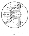
- Figure 3
- is an enlarged view of a section of the trim panel of Figure 1 in accordance with an embodiment of the invention;
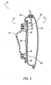
- Figure 4
- is a cross-sectional view of the door assembly of Figure 1, after assembly, in accordance with an embodiment of the invention;
- Figure 5
- is a flowchart according to a method of the invention; and
- Figure 6
- is another flowchart according to another method of the invention.
- Referring now to the drawings, wherein like numbers represent like elements, a
door assembly 10 is generally shown according to an embodiment of the present invention. - Referring now to Figures 1 and 2, the
door assembly 10 includes afirst panel 12 and asecond panel 14 and aseal 24 disposed therebetween. For purposes of convenience, thefirst panel 12 will be referred to herein as a door frame and thesecond panel 14 will be referred to herein as a trim panel. It should be noted, however, that the included illustrations of the disclosed method and apparatus may be applied in any environment having afirst panel 12 and asecond panel 14 wherein a seal is included, disposed, affixed, attached or the like therebetween. - The
door frame 12 and thetrim panel 14 attached thereto are conventionally known, and, therefore the individual components are generally represented throughout the various drawings. In this manner, the drawings are not intended to encompass all possible types or embodiments of such frames and panels, and, therefore, only represent such panels to the extent that they form adoor frame 12 andcorresponding trim panel 14. Thus, one of ordinary skill in the art will recognize that the present invention may be practiced with a door frame and a trim panel that are not exactly represented in the provided drawings. Additionally, various seals are known in the art and have been previously developed to protect contaminants, such as water, from entering into the interior of the door assembly, and it is therefore desirable to shield thetrim panel 14 and the vehicle interior from the contaminants. - In an embodiment, the
seal 24 is formed of a semi-rigid or flexible plastic sheet that comprises a water impervious thermoplastic, heat resistant material. The particular material may be selected by one of ordinary skill in the art as commercially available types of material suitable for this purpose are known. Similarly, other materials are known and used for seals, and may be adapted in accordance with the invention. One of ordinary skill in the art will recognize such materials when considering the present disclosure. - With reference now to Figure 2, the
trim panel 14 includes aninterior portion 16 and anexterior portion 18. Likewise, thedoor frame 12 includes aninterior portion 20 and anexterior portion 22. Theinterior portions trim panel 14 and thedoor frame 12 are arranged in a facing relationship and theseal 24 is illustrated therebetween. In a similar manner, theexterior portion 18 of thetrim panel 14 likewise faces the interior of the vehicle and theexterior portion 22 ofdoor panel 12 forms a portion of the exterior of the vehicle. - In one method of the invention, at least a portion of the interior portion of the
trim panel 14 preliminarily retains theseal 24. Theseal 24, as it becomes disposed between thetrim panel 14 and thedoor frame 12 provides, for example and among other functions, a shield against extemalities from entering thedoor assembly 10 and may also provide a dampening mechanism for sound and other internal features that may occur within thedoor assembly 10. In an embodiment, theseal 24 provides insulation between thedoor assembly 10 and externalities. - With continued reference to Figure 2, the
interior portion 16 of thetrim panel 14 includes at least oneretaining mechanism 26 along at least a portion oftrim panel 14. Theretaining mechanism 26 removably retains theseal 24. This feature may be beneficial for the transportation and installation of thetrim panel 14 and theseal 24 as a package. That is, until thetrim panel 14 and theseal 24 are attached to thedoor frame 12, theretaining mechanism 26 carries or transports theseal 24. Thetrim panel 14 and theseal 24 are then combined with thedoor frame 12 and form thedoor assembly 10. The details of theretaining mechanism 26 and the subsequent attachment to thedoor frame 12 will be further discussed herein. - For purposes of illustration, Figure 2 depicts two
retaining mechanisms 26 arranged at various points along thetrim panel 14. However, although tworetaining mechanisms 26 are illustrated at various points or positions alongtrim panel 14, the invention is not to be limited by the placement or number of illustratedretaining mechanisms 26. That is, the invention contemplates any combination of thetrim panel 14 having the at least oneretaining mechanism 26, such as the one herein described, for retaining theseal 24 during the assembly process. - Referring now to Figure 3, the
trim panel 14 includes theretaining mechanism 26 formed therein or thereon, and theseal 24 retained by theretaining mechanism 26. Theretaining mechanism 26 acts as a boss that extends from a portion of thetrim panel 14. Theretaining mechanism 26 forms a mushroom-like structure that has aflange 30 or the like extending from abase 32. - In the illustrated embodiment, the
retaining mechanism 26 is formed during an injection molding process that forms thetrim panel 14. Theretaining mechanism 26 is initially formed with only thebase 32 extending substantially perpendicularly from thetrim panel 14. Next, theflange 30 is formed on theretaining mechanism 26 using a heat staking process by applying heat and pressure to the end of theretaining mechanism 26. Although a heat staking process is disclosed, it is but one example to form the retaining mechanism. It will be appreciated that other suitable mechanisms exist to form theretaining mechanism 26 with theflanges 26. Thus, among other possibilities, the retainingmechanism 26 could be formed by any combination of molding, heat staking, or the like. The heat staking process may be performed before theseal 24 is connected to thetrim panel 14. It should also be noted, that the heat staking process could instead be performed after theseal 24 is connected to thetrim panel 14. - The
seal 24 defines at least oneaperture 34 at a location thereon that corresponds to a location of theretaining mechanism 26 extending from thetrim panel 14. As Figure 3 illustrates, a diameter of the aperture 34 (daperture) is larger than a diameter of the base 32 (dbase) of theretaining mechanism 26, but smaller than a diameter of the flange 30 (dflange). In one embodiment, theseal 24 is a panel structure that substantially extends entirely between thetrim panel 14 and thedoor frame 12. However, other formatives of theseal 24 are additionally contemplated in accordance with the invention. For example, theseal 24 could instead be a strip designed to run substantially along the perimeter between thetrim panel 14 and thedoor frame 12. - In the illustrated embodiment, the
aperture 34 of theseal 24 fits over retainingmechanism 26. Theseal 24 circumscribes or surrounds thebase 32 of theretaining mechanism 26 to the extent that theseal 24 remains removably retained by thetrim panel 14. Thus, the retainingmechanism 26 and thereby thetrim panel 14 provide a support structure for theseal 24 until theseal 24 is affixed to theinner portion 20 of thedoor frame 12. - In the illustrated embodiment, the
seal 24 includes afirst surface 36 and asecond surface 38. Thefirst surface 36 of theseal 24 includes an adhesive orbonding material 50 to adhere or bond theseal 24 to theinterior portion 20 of thedoor frame 12. In an embodiment, a protectorate paper or the like (not shown) may be provided to cover or shield theadhesive material 50 to preserve the adhesive properties until the protectorate is removed. Other protectorate mechanisms are additionally known that may protect the adhesion properties of this structure which will be recognized when considering the present disclosure. - The adhesive material forms a bond with the
interior portion 22 of thedoor frame 12 to affix theseal 24 to thedoor frame 12. In the illustrated embodiment, a first retaining force exists between theseal 24 and the door frame . 12, and a second retaining force exists between theseal 24 and theretaining mechanism 26. The first retaining force is configured to be greater then the second retaining force such that asdoor assembly 10 is disassembled: the removal force necessary to break the second retaining force is less than the removal force necessary to break the first retaining force. The disassembly, therefore, allows thetrim panel 14 to be removed from theseal 24 and thedoor frame 12. This is in part due to an elasticity of theseal 24 and the lengths of daperture, dbase and dflange allowing theaperture 34 ofseal 24 to pass over theflange 30 of theretaining mechanism 26. In other words, in the event that it becomes necessary to enter the interior of thedoor assembly 10, for example among others, to provide access for service technicians or the like to have access to thedoor assembly 10, or other various activities that require thattrim panel 14 be removed or separated fromdoor frame 12,seal 24 will remain affixed tointerior portion 22 ofdoor frame 12, and thereby allow theretaining mechanism 26 of thetrim panel 14 to exit theaperture 30 of theseal 24. After servicing thedoor assembly 10, if desired, the retainingmechanism 26 and theaperture 34 of the seal may be reattached. However, it is not a necessary feature that theseal 24 and theretaining mechanism 26 become reattached. - It is additionally noted that various adhering mechanisms or compounds will become readily apparent to one of ordinary skill in the art in combination with the present disclosure.
- Referring now to Figure 5, a method for manufacturing a trim assembly will now be described in accordance with an embodiment of the invention. The
trim panel 14 is formed and includes at least one projection having a base 32 in step S5.1. A retainingmechanism 26 is formed from the projection in step S5.2. Aseal 24 is arranged proximate to the trim panel in step S5.3. Theseal 24 includes at least oneaperture 34 that corresponds with the projection of thetrim panel 14, and theaperture 34 extends around thebase 32 of the projection. It should he noted that the step S5.2 for forming theretaining mechanism 26 could he performed either before, or after, step S5.3 of arranging theseal 24. - In an embodiment, therefore, the attachment of the
complete door assembly 10 is accomplished by pre-assembling thetrim panel 14 with theseal 24 to thereby form a trim assembly. It is noted that the trim assembly may also include other various elements that are generally pre-assembled with conventional door trim assemblies. In this manner, thedoor assembly 10 may be rapidly assembled by combining the trim assembly with thedoor frame 12 by simply adding pressure against each thedoor frame 12 and the trim assembly so that the adhesive 50 on theseal 24 engages and secures theseal 24 to thedoor frame 12. This permits fast assembly and eliminates the manual positioning and fastening ofseal 24 in its precisely required location within thedoor frame 12. That is, this arrangement automatically positions theseal 12 for assembly without necessitating separate measurements or manual attempts to locate the correct location. - Referring now to Figure 6, another method of manufacturing a trim assembly is described in accordance with an embodiment of the invention. The
trim panel 14 is formed having at least oneretaining mechanism 26 along a portion of thetrim panel 14 in step S6.1. Aseal 24 is positioned along thetrim panel 14 in step S6.2. Theseal 24 includes at least oneaperture 34 at a location on theseal 24 that corresponds to a location of theretaining mechanism 26 on thetrim panel 14. Theaperture 34 of theseal 24 is fit over thecorresponding retaining mechanism 26 in step S6.3. Aflange 30 is formed on theretaining mechanism 26 in step S6.4. It is noted that the flange forming step of S6.4 could instead precede the seal positioning step of S6.2 and the aperture fitting step of S6.3. - It should be emphasized that the above-described embodiments of the present invention, particularly, any "preferred" embodiments, are only possible examples of implementations, merely set forth for a clear understanding of the principles of the invention. Many variations and modifications may be made to the above-described embodiment(s) of the invention without departing substantially from the spirit and principles of the invention. All such modifications and variations are intended to be included herein within the scope of this disclosure and the present invention and protected by the following claims..
Claims (21)
- A trim assembly for attachment to a door frame (12), comprising: a trim panel (14) having an interior portion (16), wherein said interior portion (16) includes at least one retaining mechanism (26) extending therefrom; and a seal (24) having first and second sides, wherein said first side of said seal (24) is adapted to bond to the door frame (12), and wherein said second side of said seal (24) is capable of being removably retained by the interior portion (16) of said trim panel (14) by the at least one retaining mechanism (26).
- The trim assembly according to claim 1, wherein said seal (24) defines at least one aperture (34), each of said at least one aperture (34) corresponding to one of said at least one retaining mechanism (26).
- The trim assembly according to claim 2, wherein said aperture (34) is adapted to receive said at least one corresponding retaining mechanism (26).
- The trim assembly according to claim 2 or 3, wherein said bond between said first side of said seal (24) and said door frame (12) has a first retaining force and the relationship between said aperture (34) of said seal (24) and said retaining mechanism (26) has a second retaining force, wherein said first retaining forcing is greater than said second retaining force.
- The trim assembly according to one of claims 1 to 4, wherein said at least one retaining mechanism (26) includes a base (32) and a flange (30) extending therefrom.
- The trim assembly according to claim 5, wherein each of said at least one aperture (34) is adapted to circumscribe said base (32) of each of said at least one retaining mechanism (26).
- The trim assembly according to one of claims 1 to 6, wherein said at least one retaining mechanism (26) is formed in said interior portion (16).
- The trim assembly according to one of claims 1 to 7, wherein said at least one retaining mechanism (26) is formed in said interior portion (16) using a heat staking process.
- The trim assembly according to one of claims 1 to 8, wherein first side of said seal (24) includes adhesive (50) such that said adhesive (50) is adapted to bond said seal (24) to said door frame (12).
- The trim assembly according to one of claims 1 to 9, wherein said second side of said seal (24) is further removably attached to said interior portion (16) by silicone disposed along at least a portion of said seal (24) and said interior portion (16).
- The trim assembly according to one of claims 1 to 10, wherein said interior portion (16) of said panel includes a perimeter, at least two of said retaining mechanisms (26) included along said perimeter.
- A method of manufacturing a trim assembly, said method comprising the steps of: forming a trim panel (14), wherein said trim panel (14) includes at least one projection having a base, and forming a retaining mechanism (26) on an end of said projection.
- The method according to claim 12 further comprising the step of: arranging a seal (24) proximate to said trim panel (14), wherein said seal (24) includes at least one aperture (34) that corresponds with said at least one projection of said trim panel (14), and wherein said aperture (34) extends around said base of said projection.
- The method according to claim 13, wherein said step for forming said retaining mechanism (26) is performed after said step of arranging said seal (24).
- The method according to claim 12, wherein said step for forming said retaining mechanism (26) is carried out using a heat staking process.
- The method according to claim 12, wherein said retaining mechanism (26) is a flange.
- The method according to claim 12, said method further comprising the steps of: providing a door frame (12); and bonding said seal (24) to said door frame (12).
- A method of manufacturing a trim assembly, said method comprising the steps of: forming a trim panel (14) having at least retaining mechanism (26) along a portion of said trim panel (14); positioning a seal (24) along said trim panel (14), wherein said seal (24) includes at least one aperture (34) at a location on said seal (24) that corresponds to a location of said at least one retaining mechanism (26); and fitting at least one of said at least one apertures (34) of said seal (24) over at least one of said corresponding at least one retaining mechanism (26).
- The method from claim 18, said method further comprising the step of: forming a flange (30) on said at least one retaining mechanism (26).
- The method from claim 19, wherein said forming a flange step precedes said positioning a seal step and said fitting each of said at least one apertures of said seal step.
- The method from claim 19, wherein said flange (30) is formed using a heat staking process.
Applications Claiming Priority (1)
| Application Number | Priority Date | Filing Date | Title |
|---|---|---|---|
| US11/048,653 US7108313B2 (en) | 2005-01-28 | 2005-01-28 | Trim assembly and method of manufacturing same |
Publications (1)
| Publication Number | Publication Date |
|---|---|
| EP1686011A1 true EP1686011A1 (en) | 2006-08-02 |
Family
ID=36204224
Family Applications (1)
| Application Number | Title | Priority Date | Filing Date |
|---|---|---|---|
| EP06000552A Withdrawn EP1686011A1 (en) | 2005-01-28 | 2006-01-12 | Trim assembly and method of manufacturing same |
Country Status (2)
| Country | Link |
|---|---|
| US (1) | US7108313B2 (en) |
| EP (1) | EP1686011A1 (en) |
Cited By (1)
| Publication number | Priority date | Publication date | Assignee | Title |
|---|---|---|---|---|
| EP2006134A1 (en) * | 2007-06-21 | 2008-12-24 | Ford Global Technologies, LLC | Vehicle door |
Families Citing this family (40)
| Publication number | Priority date | Publication date | Assignee | Title |
|---|---|---|---|---|
| US6991278B2 (en) * | 2001-05-03 | 2006-01-31 | The Xlo Group Of Companies, Inc. | Sealing systems and related methods for automotive interior trim panels and the like |
| EP1621383B1 (en) * | 2003-05-07 | 2007-12-12 | Grupo Antolin-Ingenieria, S.A. | Door |
| DE10326154B4 (en) * | 2003-06-06 | 2005-09-08 | Johnson Controls Interiors Gmbh & Co. Kg | Door module for vehicle door |
| WO2005084978A1 (en) * | 2004-03-05 | 2005-09-15 | Hayashi Engineering Inc. | Sunvisor for automobile and sound absorbing structure of automobile running on road |
| US20070113485A1 (en) * | 2005-11-22 | 2007-05-24 | Arvinmeritor Technology, Llc | Door module positioning system |
| PT2152535E (en) * | 2007-05-16 | 2012-10-04 | Uniteam Italia Srl | Cover item provided with a seal and production method thereof |
| US8870259B2 (en) * | 2008-11-12 | 2014-10-28 | Irvin Automotive Products, Inc. | Hybrid visor |
| US9812684B2 (en) | 2010-11-09 | 2017-11-07 | GM Global Technology Operations LLC | Using elastic averaging for alignment of battery stack, fuel cell stack, or other vehicle assembly |
| US8985674B2 (en) * | 2011-08-02 | 2015-03-24 | Toyota Boshoku Kabushiki Kaisha | Door trim for vehicle |
| DE202012102178U1 (en) * | 2012-06-13 | 2013-09-18 | Carcoustics Techconsult Gmbh | Distance device for stacking identically shaped plastic moldings |
| US9618026B2 (en) | 2012-08-06 | 2017-04-11 | GM Global Technology Operations LLC | Semi-circular alignment features of an elastic averaging alignment system |
| US9463538B2 (en) | 2012-08-13 | 2016-10-11 | GM Global Technology Operations LLC | Alignment system and method thereof |
| US20140041185A1 (en) * | 2012-08-13 | 2014-02-13 | GM Global Technology Operations LLC | Elastic tube alignment and attachment system and method for precisely locating and attaching components |
| US9556890B2 (en) | 2013-01-31 | 2017-01-31 | GM Global Technology Operations LLC | Elastic alignment assembly for aligning mated components and method of reducing positional variation |
| US9388838B2 (en) | 2013-04-04 | 2016-07-12 | GM Global Technology Operations LLC | Elastic retaining assembly for matable components and method of assembling |
| US9278642B2 (en) | 2013-04-04 | 2016-03-08 | GM Global Technology Operations LLC | Elastically deformable flange locator arrangement and method of reducing positional variation |
| US9447840B2 (en) | 2013-06-11 | 2016-09-20 | GM Global Technology Operations LLC | Elastically deformable energy management assembly and method of managing energy absorption |
| US9488205B2 (en) | 2013-07-12 | 2016-11-08 | GM Global Technology Operations LLC | Alignment arrangement for mated components and method |
| US9303667B2 (en) | 2013-07-18 | 2016-04-05 | Gm Global Technology Operations, Llc | Lobular elastic tube alignment system for providing precise four-way alignment of components |
| US9863454B2 (en) | 2013-08-07 | 2018-01-09 | GM Global Technology Operations LLC | Alignment system for providing precise alignment and retention of components of a sealable compartment |
| US9458876B2 (en) | 2013-08-28 | 2016-10-04 | GM Global Technology Operations LLC | Elastically deformable alignment fastener and system |
| US9463831B2 (en) | 2013-09-09 | 2016-10-11 | GM Global Technology Operations LLC | Elastic tube alignment and fastening system for providing precise alignment and fastening of components |
| US9457845B2 (en) | 2013-10-02 | 2016-10-04 | GM Global Technology Operations LLC | Lobular elastic tube alignment and retention system for providing precise alignment of components |
| US9511802B2 (en) | 2013-10-03 | 2016-12-06 | GM Global Technology Operations LLC | Elastically averaged alignment systems and methods |
| US9669774B2 (en) | 2013-10-11 | 2017-06-06 | GM Global Technology Operations LLC | Reconfigurable vehicle interior assembly |
| US9481317B2 (en) | 2013-11-15 | 2016-11-01 | GM Global Technology Operations LLC | Elastically deformable clip and method |
| US9428123B2 (en) | 2013-12-12 | 2016-08-30 | GM Global Technology Operations LLC | Alignment and retention system for a flexible assembly |
| US9447806B2 (en) | 2013-12-12 | 2016-09-20 | GM Global Technology Operations LLC | Self-retaining alignment system for providing precise alignment and retention of components |
| US9599279B2 (en) | 2013-12-19 | 2017-03-21 | GM Global Technology Operations LLC | Elastically deformable module installation assembly |
| US9446722B2 (en) | 2013-12-19 | 2016-09-20 | GM Global Technology Operations LLC | Elastic averaging alignment member |
| US9541113B2 (en) | 2014-01-09 | 2017-01-10 | GM Global Technology Operations LLC | Elastically averaged alignment systems and methods |
| US9428046B2 (en) | 2014-04-02 | 2016-08-30 | GM Global Technology Operations LLC | Alignment and retention system for laterally slideably engageable mating components |
| US9657807B2 (en) | 2014-04-23 | 2017-05-23 | GM Global Technology Operations LLC | System for elastically averaging assembly of components |
| US9429176B2 (en) | 2014-06-30 | 2016-08-30 | GM Global Technology Operations LLC | Elastically averaged alignment systems and methods |
| US9758110B2 (en) | 2015-01-12 | 2017-09-12 | GM Global Technology Operations LLC | Coupling system |
| US10107319B2 (en) | 2015-03-02 | 2018-10-23 | GM Global Technology Operations LLC | Elastically averaged alignment systems and methods |
| US10272756B2 (en) | 2016-03-10 | 2019-04-30 | Honda Motor Co., Ltd. | Vehicle door assembly, and methods of use and manufacture thereof |
| JP6487894B2 (en) * | 2016-11-17 | 2019-03-20 | しげる工業株式会社 | Sound absorbing material mounting structure |
| US11511610B2 (en) | 2018-11-12 | 2022-11-29 | Shape Corp. | Vehicle door carrier with integrated edge seal and method of manufacture |
| JP7144494B2 (en) * | 2020-09-29 | 2022-09-29 | 本田技研工業株式会社 | Door structure and assembly method for vehicle door |
Citations (3)
| Publication number | Priority date | Publication date | Assignee | Title |
|---|---|---|---|---|
| DE8508291U1 (en) * | 1985-03-20 | 1989-05-03 | Herrmann, Hilmar, 5630 Remscheid | Waterproof clothing to cover body parts against moisture penetrating the passenger compartment from outside |
| DE10110753A1 (en) * | 2001-03-07 | 2002-09-19 | Bayerische Motoren Werke Ag | Vehicle door consists of an outer sheet metal layer, an inner sheet metal layer with an opening, a planar seal and a door inner lining |
| US20040169396A1 (en) * | 2003-02-28 | 2004-09-02 | Dooley David J. | Method of forming a vehicle panel assembly |
Family Cites Families (9)
| Publication number | Priority date | Publication date | Assignee | Title |
|---|---|---|---|---|
| DE3502056A1 (en) * | 1985-01-23 | 1986-07-24 | Hilmar 5630 Remscheid Herrmann | Water protection coating for covering vehicle body parts to protect against moisture penetrating into the passenger compartment from outside |
| DE19835877B4 (en) * | 1997-08-07 | 2006-03-09 | Kabushiki Kaisha Toyota Jidoshokki, Kariya | vehicle window |
| DE19954648B4 (en) * | 1999-11-13 | 2007-10-25 | Brose Fahrzeugteile Gmbh & Co. Kommanditgesellschaft, Coburg | Vehicle door with a door body separated in a wet room and a dry room |
| US6422640B2 (en) * | 1999-12-30 | 2002-07-23 | Delphi Technologies, Inc. | Door trim panel assembly and method of making |
| US6412852B1 (en) * | 2000-07-25 | 2002-07-02 | Foamade Industries, Inc. | Water, dust and sound attenuating barrier and trim panel module and method for assembling within a vehicle door |
| US6991278B2 (en) * | 2001-05-03 | 2006-01-31 | The Xlo Group Of Companies, Inc. | Sealing systems and related methods for automotive interior trim panels and the like |
| US7055887B2 (en) * | 2004-02-25 | 2006-06-06 | Cadillac Products Automotive Company | Water and sound shield having raised sealing rib |
| US6955392B2 (en) * | 2004-03-16 | 2005-10-18 | Lear Corporation | Self sealing heat stake on an overmolded panel |
| US7059659B2 (en) * | 2004-07-26 | 2006-06-13 | Lear Corporation | Vehicle door barrier panel having removable attachment tabs |
-
2005
- 2005-01-28 US US11/048,653 patent/US7108313B2/en not_active Expired - Fee Related
-
2006
- 2006-01-12 EP EP06000552A patent/EP1686011A1/en not_active Withdrawn
Patent Citations (3)
| Publication number | Priority date | Publication date | Assignee | Title |
|---|---|---|---|---|
| DE8508291U1 (en) * | 1985-03-20 | 1989-05-03 | Herrmann, Hilmar, 5630 Remscheid | Waterproof clothing to cover body parts against moisture penetrating the passenger compartment from outside |
| DE10110753A1 (en) * | 2001-03-07 | 2002-09-19 | Bayerische Motoren Werke Ag | Vehicle door consists of an outer sheet metal layer, an inner sheet metal layer with an opening, a planar seal and a door inner lining |
| US20040169396A1 (en) * | 2003-02-28 | 2004-09-02 | Dooley David J. | Method of forming a vehicle panel assembly |
Cited By (1)
| Publication number | Priority date | Publication date | Assignee | Title |
|---|---|---|---|---|
| EP2006134A1 (en) * | 2007-06-21 | 2008-12-24 | Ford Global Technologies, LLC | Vehicle door |
Also Published As
| Publication number | Publication date |
|---|---|
| US20060170242A1 (en) | 2006-08-03 |
| US7108313B2 (en) | 2006-09-19 |
Similar Documents
| Publication | Publication Date | Title |
|---|---|---|
| US7108313B2 (en) | Trim assembly and method of manufacturing same | |
| EP1838545B1 (en) | Encapsulated fixed window module | |
| US6205642B1 (en) | Method of mounting a body side molding | |
| EP1658199B1 (en) | Vehicle body panel with integral clip | |
| US7971923B2 (en) | Door trim panel assembly and method | |
| US5529366A (en) | Automotive window peripheral framing assembly and method of installing same | |
| US5475947A (en) | Flexible sealing unit for movable windows | |
| EP1493650A1 (en) | Car roof module | |
| US20050253416A1 (en) | Modular automotive door trim panel construction | |
| JPH0514655B2 (en) | ||
| EP1751389B1 (en) | One-piece plastic retainer with integrated water management feature | |
| JP2005518305A (en) | ROOF MODULE MODULE AND METHOD OF ASSEMBLING THE MODULE ON AUTOMOBILE | |
| US10994593B2 (en) | Mounting structure for doorframe molding | |
| JP4206878B2 (en) | Car fender panel mounting structure | |
| EP3241696B1 (en) | Window module, vehicle body, methods for manufacturing a vehicle body and for replacing a glazing of a vehicle body | |
| US4719736A (en) | Removable window assembly | |
| CN114852005A (en) | Knee airbag cover | |
| US20070024082A1 (en) | Trim panel including integrally formed members | |
| EP0691231B1 (en) | Window glass sealing and fixing arrangements | |
| US7703830B2 (en) | Window assembly having an integral bonding system | |
| JPH05330343A (en) | Door trim with service hole cover | |
| JP3185281B2 (en) | Mounting structure of weather strip for automobile | |
| JP2001315665A (en) | Flexible foam substrate and component mounting structure using the same foam substrate | |
| KR101007075B1 (en) | Structure of door trim | |
| JP3468360B2 (en) | Outlet grill structure |
Legal Events
| Date | Code | Title | Description |
|---|---|---|---|
| PUAI | Public reference made under article 153(3) epc to a published international application that has entered the european phase |
Free format text: ORIGINAL CODE: 0009012 |
|
| AK | Designated contracting states |
Kind code of ref document: A1 Designated state(s): AT BE BG CH CY CZ DE DK EE ES FI FR GB GR HU IE IS IT LI LT LU LV MC NL PL PT RO SE SI SK TR |
|
| AX | Request for extension of the european patent |
Extension state: AL BA HR MK YU |
|
| 17P | Request for examination filed |
Effective date: 20070202 |
|
| 17Q | First examination report despatched |
Effective date: 20070301 |
|
| AKX | Designation fees paid |
Designated state(s): DE GB |
|
| STAA | Information on the status of an ep patent application or granted ep patent |
Free format text: STATUS: THE APPLICATION IS DEEMED TO BE WITHDRAWN |
|
| 18D | Application deemed to be withdrawn |
Effective date: 20071113 |