EP1691994B1 - Determination d'un mouvement relatif entre le chassis et la carrosserie d'un vehicule a roues - Google Patents
Determination d'un mouvement relatif entre le chassis et la carrosserie d'un vehicule a roues Download PDFInfo
- Publication number
- EP1691994B1 EP1691994B1 EP04791340A EP04791340A EP1691994B1 EP 1691994 B1 EP1691994 B1 EP 1691994B1 EP 04791340 A EP04791340 A EP 04791340A EP 04791340 A EP04791340 A EP 04791340A EP 1691994 B1 EP1691994 B1 EP 1691994B1
- Authority
- EP
- European Patent Office
- Prior art keywords
- wheeled vehicle
- vehicle
- chassis
- vehicle body
- movement
- Prior art date
- Legal status (The legal status is an assumption and is not a legal conclusion. Google has not performed a legal analysis and makes no representation as to the accuracy of the status listed.)
- Expired - Lifetime
Links
Images


Classifications
-
- B—PERFORMING OPERATIONS; TRANSPORTING
- B60—VEHICLES IN GENERAL
- B60G—VEHICLE SUSPENSION ARRANGEMENTS
- B60G17/00—Resilient suspensions having means for adjusting the spring or vibration-damper characteristics, for regulating the distance between a supporting surface and a sprung part of vehicle or for locking suspension during use to meet varying vehicular or surface conditions, e.g. due to speed or load
- B60G17/015—Resilient suspensions having means for adjusting the spring or vibration-damper characteristics, for regulating the distance between a supporting surface and a sprung part of vehicle or for locking suspension during use to meet varying vehicular or surface conditions, e.g. due to speed or load the regulating means comprising electric or electronic elements
- B60G17/016—Resilient suspensions having means for adjusting the spring or vibration-damper characteristics, for regulating the distance between a supporting surface and a sprung part of vehicle or for locking suspension during use to meet varying vehicular or surface conditions, e.g. due to speed or load the regulating means comprising electric or electronic elements characterised by their responsiveness, when the vehicle is travelling, to specific motion, a specific condition, or driver input
-
- B—PERFORMING OPERATIONS; TRANSPORTING
- B60—VEHICLES IN GENERAL
- B60G—VEHICLE SUSPENSION ARRANGEMENTS
- B60G17/00—Resilient suspensions having means for adjusting the spring or vibration-damper characteristics, for regulating the distance between a supporting surface and a sprung part of vehicle or for locking suspension during use to meet varying vehicular or surface conditions, e.g. due to speed or load
- B60G17/015—Resilient suspensions having means for adjusting the spring or vibration-damper characteristics, for regulating the distance between a supporting surface and a sprung part of vehicle or for locking suspension during use to meet varying vehicular or surface conditions, e.g. due to speed or load the regulating means comprising electric or electronic elements
-
- B—PERFORMING OPERATIONS; TRANSPORTING
- B60—VEHICLES IN GENERAL
- B60G—VEHICLE SUSPENSION ARRANGEMENTS
- B60G17/00—Resilient suspensions having means for adjusting the spring or vibration-damper characteristics, for regulating the distance between a supporting surface and a sprung part of vehicle or for locking suspension during use to meet varying vehicular or surface conditions, e.g. due to speed or load
- B60G17/015—Resilient suspensions having means for adjusting the spring or vibration-damper characteristics, for regulating the distance between a supporting surface and a sprung part of vehicle or for locking suspension during use to meet varying vehicular or surface conditions, e.g. due to speed or load the regulating means comprising electric or electronic elements
- B60G17/019—Resilient suspensions having means for adjusting the spring or vibration-damper characteristics, for regulating the distance between a supporting surface and a sprung part of vehicle or for locking suspension during use to meet varying vehicular or surface conditions, e.g. due to speed or load the regulating means comprising electric or electronic elements characterised by the type of sensor or the arrangement thereof
-
- B—PERFORMING OPERATIONS; TRANSPORTING
- B60—VEHICLES IN GENERAL
- B60G—VEHICLE SUSPENSION ARRANGEMENTS
- B60G17/00—Resilient suspensions having means for adjusting the spring or vibration-damper characteristics, for regulating the distance between a supporting surface and a sprung part of vehicle or for locking suspension during use to meet varying vehicular or surface conditions, e.g. due to speed or load
- B60G17/015—Resilient suspensions having means for adjusting the spring or vibration-damper characteristics, for regulating the distance between a supporting surface and a sprung part of vehicle or for locking suspension during use to meet varying vehicular or surface conditions, e.g. due to speed or load the regulating means comprising electric or electronic elements
- B60G17/019—Resilient suspensions having means for adjusting the spring or vibration-damper characteristics, for regulating the distance between a supporting surface and a sprung part of vehicle or for locking suspension during use to meet varying vehicular or surface conditions, e.g. due to speed or load the regulating means comprising electric or electronic elements characterised by the type of sensor or the arrangement thereof
- B60G17/01908—Acceleration or inclination sensors
-
- B—PERFORMING OPERATIONS; TRANSPORTING
- B60—VEHICLES IN GENERAL
- B60G—VEHICLE SUSPENSION ARRANGEMENTS
- B60G2400/00—Indexing codes relating to detected, measured or calculated conditions or factors
- B60G2400/20—Speed
- B60G2400/202—Piston speed; Relative velocity between vehicle body and wheel
-
- B—PERFORMING OPERATIONS; TRANSPORTING
- B60—VEHICLES IN GENERAL
- B60G—VEHICLE SUSPENSION ARRANGEMENTS
- B60G2400/00—Indexing codes relating to detected, measured or calculated conditions or factors
- B60G2400/25—Stroke; Height; Displacement
- B60G2400/252—Stroke; Height; Displacement vertical
-
- B—PERFORMING OPERATIONS; TRANSPORTING
- B60—VEHICLES IN GENERAL
- B60G—VEHICLE SUSPENSION ARRANGEMENTS
- B60G2400/00—Indexing codes relating to detected, measured or calculated conditions or factors
- B60G2400/60—Load
- B60G2400/63—Location of the center of gravity
-
- B—PERFORMING OPERATIONS; TRANSPORTING
- B60—VEHICLES IN GENERAL
- B60G—VEHICLE SUSPENSION ARRANGEMENTS
- B60G2400/00—Indexing codes relating to detected, measured or calculated conditions or factors
- B60G2400/90—Other conditions or factors
- B60G2400/95—Position of vehicle body elements
- B60G2400/954—Wheelbase
-
- B—PERFORMING OPERATIONS; TRANSPORTING
- B60—VEHICLES IN GENERAL
- B60G—VEHICLE SUSPENSION ARRANGEMENTS
- B60G2500/00—Indexing codes relating to the regulated action or device
- B60G2500/30—Height or ground clearance
-
- B—PERFORMING OPERATIONS; TRANSPORTING
- B60—VEHICLES IN GENERAL
- B60G—VEHICLE SUSPENSION ARRANGEMENTS
- B60G2600/00—Indexing codes relating to particular elements, systems or processes used on suspension systems or suspension control systems
- B60G2600/18—Automatic control means
- B60G2600/187—Digital Controller Details and Signal Treatment
- B60G2600/1873—Model Following
-
- B—PERFORMING OPERATIONS; TRANSPORTING
- B60—VEHICLES IN GENERAL
- B60G—VEHICLE SUSPENSION ARRANGEMENTS
- B60G2800/00—Indexing codes relating to the type of movement or to the condition of the vehicle and to the end result to be achieved by the control action
- B60G2800/01—Attitude or posture control
- B60G2800/012—Rolling condition
-
- B—PERFORMING OPERATIONS; TRANSPORTING
- B60—VEHICLES IN GENERAL
- B60G—VEHICLE SUSPENSION ARRANGEMENTS
- B60G2800/00—Indexing codes relating to the type of movement or to the condition of the vehicle and to the end result to be achieved by the control action
- B60G2800/01—Attitude or posture control
- B60G2800/014—Pitch; Nose dive
-
- B—PERFORMING OPERATIONS; TRANSPORTING
- B60—VEHICLES IN GENERAL
- B60G—VEHICLE SUSPENSION ARRANGEMENTS
- B60G2800/00—Indexing codes relating to the type of movement or to the condition of the vehicle and to the end result to be achieved by the control action
- B60G2800/90—System Controller type
- B60G2800/91—Suspension Control
- B60G2800/912—Attitude Control; levelling control
-
- B—PERFORMING OPERATIONS; TRANSPORTING
- B60—VEHICLES IN GENERAL
- B60G—VEHICLE SUSPENSION ARRANGEMENTS
- B60G2800/00—Indexing codes relating to the type of movement or to the condition of the vehicle and to the end result to be achieved by the control action
- B60G2800/90—System Controller type
- B60G2800/91—Suspension Control
- B60G2800/914—Height Control System
Definitions
- the invention relates to an arrangement and a method for determining a relative movement of a chassis and a movably connected to the chassis vehicle body of a wheeled vehicle.
- An arrangement according to the preamble of claim 1 and a method according to the preamble of claim 6 are made EP-A-1 002 709 known.
- Suspensions of a spring-loaded connection between a vehicle body and a chassis or ride height of the relative movement between the chassis and the vehicle body are used for example as input variables of systems for adjusting a damping of the relative movement and / or other systems for setting and / or monitoring properties of the chassis.
- the invention relates to a combination of the arrangement with at least one of the aforementioned systems or with any combination of such systems.
- level sensors are relatively expensive and subject to high stresses during their use in a motor vehicle.
- Reasons for this are in particular mechanical loads z. As by particles and stones, while driving in the area between wheels and vehicle body be whirled up, humidity and temperature changes.
- the measuring device preferably has acceleration sensors for measuring the three linear accelerations and yaw rate sensors for measuring the at least two yaw rates, wherein the acceleration sensors and yaw rate sensors can be parts of a prefabricated device unit designed for installation in the wheeled vehicle.
- This unit is a special embodiment of a so-called inertial measurement unit (IMU).
- IMU inertial measurement unit
- the IMU is designed to be attached to or near the center of gravity of a wheeled vehicle.
- the center of gravity of the wheeled vehicle or a vehicle body of the wheeled vehicle is within the unit.
- the three linear accelerations are measurable by the measuring device as linearly independent measured variables.
- the directions of the respective accelerations or acceleration components detected by the acceleration sensors form the axes of a three-dimensional rectangular coordinate system.
- the measuring device is configured in such a way that the at least two axes run in pairs perpendicular to one another.
- the measuring device can, for. B. have a separate sensor for each measurement. However, there are also sensors that measure two of the measured quantities mentioned at the same time (eg two accelerations or two yaw rates).
- the measuring sensors of the measuring device for measuring the rotation rates and for measuring the linear accelerations are attached to the vehicle chassis which is movable relative to a vehicle chassis.
- the vehicle chassis which is movable relative to a vehicle chassis.
- the range of the center of gravity of the wheeled vehicle or the area of the center of gravity of a vehicle body offers.
- Acceleration sensors measure, depending on the orientation of the vehicle, a measured quantity influenced by the gravitational force of gravity. When the vehicle is at a standstill, the accelerometer measures only the effects of gravitational force. The actual acceleration then does not occur in the measured size.
- the gravity acceleration-changed dynamic acceleration quantity is referred to as the effective acceleration magnitude.
- the effective acceleration values are used in determining the relative motion of the chassis and the vehicle body. Therefore, gravitational force or gravitational force is taken into account, which actually influences the relative movement of the chassis and the vehicle bodywork.
- a correction of the effective acceleration values, the z. B. by integrating the measured rotation rate and by determining the orientation of the vehicle relative to a Erdfesten coordinate system would be possible is not required.
- gravity affects the vehicle in different ways and should also be taken into account.
- the relative movement between the vehicle body and the chassis can be determined without level sensors. This also applies to cornering and / or driving on inclined roads or inclined surfaces (laterally and / or inclined forward).
- the sensors for measuring the linear accelerations and yaw rates can also be used for other purposes (eg as input variables for further electronic systems such as an anti-lock brake system or the electronic stability program). Furthermore, it is possible to monitor existing level sensors with regard to a reliable determination of the suspension travel and / or the height positions. If the level sensors temporarily supply implausible measured values, u. Under consideration of further measured variables (such as driving speed, steering angle) it can be decided whether it is still possible to operate systems that use the ride height as input variables. For example, it may be decided that the height levels (or equivalent sizes) determined in the manner according to the invention can still be used, since the level sensors are disturbed by environmental influences.
- a plurality of current movement positions are calculated, wherein each of the movement positions is a measure of a distance between the vehicle body and at least one wheel of the chassis.
- the instantaneous movement position is calculated taking into account a, in particular damped, suspension between at least one of the wheels of the wheeled vehicle and a vehicle body.
- the evaluation device can have a calculation unit which is designed to calculate the relative movement.
- the calculation unit has z. B. on a microprocessor.
- Fig. 1 illustrated road vehicle 20 has two front wheels and two rear wheels, of which the right front wheel is designated by the reference numeral 22 and of which the right rear wheel is designated by the reference numeral 24.
- the front wheels are associated with a front axle 26.
- the rear wheels are associated with a rear axle 27.
- the wheels assigned to an axle rotate when driving straight ahead of the road vehicle 20 coaxial, ie they have a common axis of rotation.
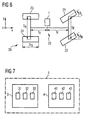
- a measuring device 1 is arranged, which is connected to an evaluation device 9. As in Fig. 7 is shown, the measuring device 1, for example, an acceleration measuring device 3 and a rotation rate measuring device 4.
- the measuring device 1 is in particular a prefabricated structural unit, wherein the corresponding measuring sensors for measuring the accelerations and rotation rates are arranged relative to each other fixed position in the unit.
- the structural unit is preferably intended to be fixed to or near the center of gravity of a motor vehicle, with a particular orientation in the motor vehicle being sought.
- the acceleration measuring device 3 has three linear acceleration sensors 31, 32, 33 ( Fig. 7 ) arranged such that each one of the acceleration sensors measures an acceleration or acceleration component of the vehicle in the direction of the axes of a Cartesian coordinate system, the x-axis pointing forwardly in the longitudinal direction of the vehicle, the y-axis directed transverse to the longitudinal axis, and the z-axis (horizontally oriented vehicle) points vertically upwards.
- FIG Fig. 6 Such a coordinate system is shown schematically in FIG Fig. 6 shown.
- This figure shows a road motor vehicle 20 with two steerable front wheels 21, 22 and two non-steerable rear wheels 23, 24.
- the front wheels are turned in the illustrated state to the left and have against the x-axis a steering angle of ⁇ L (left front wheel 21) and ⁇ R (right front wheel 22).
- the front wheels 21, 22 have a distance (wheelbase) s F
- the rear wheels 23, 24 a distance s R from each other.
- r R denotes the radius of the rear wheels 23, 24.
- the measuring device 1 In the longitudinal direction approximately in the middle of a vehicle body 25, the measuring device 1 is arranged. She has in the longitudinal direction a distance l F from the axis of the front wheels 21, 22 and a distance l R from the axis of the rear wheels 23, 24th
- the invention is not limited to wheeled vehicles with front wheel steering. Rather, z. B. also be the rear wheels steerable.
- FIG. 2 An embodiment of the in Fig. 1 shown arrangement is in Fig. 2 shown.
- the acceleration measuring device 3 is connected to the evaluation device 9 via a filter device 5.
- the rotation rate measuring device 4 is likewise connected to the evaluation device 9 via the filter device 5.
- filter device 5 is representative of other filter devices, in addition to the in Fig. 1 to Fig. 3 arrangements shown or may be provided in modified arrangements.
- the filtering of measurement signals and / or signals derived therefrom by the filter devices serves, in particular, to eliminate any noise present and to eliminate high-frequency fluctuations of the measurement signals, for example due to vibrations of the vehicle body.
- the filter devices may in particular have at least one low-pass filter and / or at least one band-pass filter.
- the filter device 5 filters the acceleration signals measured by the acceleration measuring sensors of the acceleration measuring device 3 and the rotation rate signals measured by the rotation rate measuring sensors of the rotation rate measuring device 4 before these are transmitted to the evaluation device 9.
- Fig. 3 shows the measuring device 1 and the evaluation device 9 may be arranged together with other units and / or devices in a common housing 2.
- the evaluation device 9 may have a calculation unit 11 and a monitoring device 10.
- the calculation unit 11 is used to calculate the relative movements of the vehicle body and chassis.
- the monitoring device 10 serves to monitor the measuring signals generated by the measuring device 1.
- the monitoring device 10 Using measurement signals of a steering angle and a vehicle speed, which are received via an input 6, the monitoring device 10 carries out a monitoring of at least one of the variables measured by the measuring device 1.
- the monitoring device 10 uses at least two angles (the roll angle and pitch angle of the vehicle obtained by integrating the rotation rates) for monitoring the linear accelerations, which are a measure of the orientation of the vehicle in an earth-fixed coordinate system. In this way, it can take into account that the measured linear accelerations, depending on the orientation of the vehicle relative to the earth-fixed coordinate system, contain a component which is due to the gravitational attraction.
- the calculation unit 11 z. B. be connected to a damping actuator 12 to (as already explained) to adjust a damping of a suspension between the chassis and the vehicle body.
- a damping actuator 12 Via an interface 13, with the z. B. the damping actuator 12 is connected (and may alternatively be connected directly to the computing unit 11), corresponding information about such a driving situation can be output to a system that the ride heights and / or measured by the measuring device linear accelerations and / or yaw rates are used as input variables.
- the vehicle body is considered a rigid body, i. H. no elasticities of the vehicle body are allowed. However, a (particularly damped) suspension between the wheels and the vehicle body is taken into account. Furthermore, three degrees of freedom of the relative movement between the chassis and the vehicle body are permitted, namely a linear movement in the z-direction (eg the movement of a point in the vehicle body on which the measuring device measures), a first rotational movement about one horizontal in the vehicle extending first axis of rotation (in particular the x-axis) and a second rotational movement about a horizontally extending in the vehicle second axis of rotation (in particular the y-axis), which is transverse to the first axis of rotation.
- a linear movement in the z-direction eg the movement of a point in the vehicle body on which the measuring device measures
- a first rotational movement about one horizontal in the vehicle extending first axis of rotation in particular the x-axis
- FIG. 2 schematically illustrates the model.
- a vehicle body 28 has a center of gravity CG and is provided with springs 40, 41, 43 (only three of the four wheels are shown in the two figures) and with damping members 44 acting parallel to the springs 40, 41, 43. 45, 47 individually connected to the four wheels 21, 22, 23, 24. Since the wheels 21, 22, 23, 24 are not directly mechanically coupled with each other, one can also speak of a five-mass model.
- the wheels 21, 22, 23, 24 rest on the ground 30 (eg, a roadway). However, it has been found that under certain conditions the five-mass model is equivalent to a two-mass model in which the wheels and other parts of the chassis form one mass and the vehicle body forms the other mass.
- ⁇ R , ⁇ P , k are parameters of the vehicle which correspond to a linear spring force of the respective movement component of the degree of freedom
- ⁇ R , ⁇ P , ⁇ parameters of the vehicle which correspond to a linear damping term of the respective movement component c R , c P others
- All parameters can be determined beforehand, for example, experimentally and / or mathematically for a particular vehicle or vehicle type.
- the differential equations can be solved (especially numeric) and repeatedly determine the movements in the three degrees of freedom ⁇ , ⁇ and ⁇ z (z. B. with a frequency of more than 100 Hz).
- this model precedes the vehicle body as a rigid body and is therefore well suited for driving motor vehicles on roads.
- the model takes into account, as described, rolling and pitching movements and is therefore particularly suitable for driving situations and / or vehicles in which such movements occur. This is especially the case with vehicles located high above the chassis center of gravity of the vehicle body of the case, for. B. in trucks and off-road vehicles.
Landscapes
- Engineering & Computer Science (AREA)
- Mechanical Engineering (AREA)
- Vehicle Body Suspensions (AREA)
- Length Measuring Devices With Unspecified Measuring Means (AREA)
- Control Of Driving Devices And Active Controlling Of Vehicle (AREA)
Claims (10)
- Dispositif pour la détermination d'un mouvement relatif entre un châssis et une carrosserie d'un véhicule sur roues (20) reliée au châssis avec possibilité de mouvement, comprenant- un dispositif de mesure (1) disposé ou pouvant être disposé dans le véhicule sur roues (20), le dispositif de mesure (1) étant construit pour mesurer trois accélérations linéaires du véhicule sur roues (20) dirigées à chaque fois transversalement entre elles et au moins deux vitesses de rotation, dont chacune est celle d'un mouvement de rotation ou d'une composante d'un mouvement de rotation autour d'un axe de coordonnées du véhicule sur roues (20), les au moins deux axes de coordonnées s'étendant à chaque fois transversalement entre eux, et- un dispositif d'analyse (9) qui est combiné au dispositif de mesure (1) et construit pour déterminer la position instantanée du mouvement relatif à l'aide des trois accélérations linéaires et des au moins deux vitesses de rotation,- le dispositif d'analyse (9) présentant une unité de calcul (11) qui est construite pour calculer une pluralité de positions instantanées de mouvement à l'aide des au moins deux vitesses de rotation et des trois accélérations linéaires, ,caractérisé en ce que
chacune des positions de mouvement est une mesure pour une distance entre la carrosserie du véhicule et au moins une roue du châssis. - Dispositif selon la revendication 1, dans lequel le dispositif de mesure (1) comprend des capteurs d'accélération (31, 32, 33) pour la mesure des accélérations linéaires et des capteurs de vitesse de rotation (41, 42, 43) pour la mesure des vitesses de rotation, et dans lequel les capteurs d'accélération (31, 32, 33) et les capteurs de vitesse de rotation font partie d'une unité technique d'appareillage (2) préalablement fabriquée, destinée à être montée dans le véhicule sur roues (20).
- Dispositif selon la revendication 1 ou 2, dans lequel le dispositif de mesure (1) est construit de telle manière que les trois accélérations linéaires puissent être mesurées sous la forme de grandeurs mesurées linéairement indépendantes les unes des autres.
- Dispositif selon une des revendications 1 à 3, dans lequel le dispositif de mesure (1) est construit de telle manière que les au moins deux axes de coordonnées s'étendent perpendiculairement entre eux par paires.
- Dispositif selon une des revendications 1 à 4, dans lequel le dispositif d'analyse (9) présente une unité de calcul (11) qui est construite pour calculer la position instantanée de mouvement en prenant en compte une suspension (40, 41, 43), en particulier amortie, interposée entre au moins une des roues (21, 22, 23, 24) du véhicule sur roues (20) et une carrosserie de véhicule (28).
- Procédé pour déterminer un mouvement relatif entre un châssis et une carrosserie de véhicule reliée au châssis avec possibilité de mouvement, dans lequel- dans le véhicule sur roues (20), on mesure trois accélérations linéaires du véhicule sur roues (20) dirigées à chaque fois transversalement entre elles et au moins deux vitesses de rotation, dont chacune est celle d'un mouvement de rotation ou d'une composante d'un mouvement de rotation autour d'un axe de coordonnée du véhicule sur roues (20), les au moins deux axes de coordonnées s'étendant à chaque fois transversalement entre eux, et- on détermine une position instantanée de mouvement du mouvement relatif à l'aide des trois accélérations linéaires et des au moins deux vitesses de rotation,;- on calcule une pluralité de positions instantanées de mouvement à l'aide des au moins deux vitesses de rotation et des trois accélérations linéaires, caractérisé en ce que- chacune des positions de mouvement est une mesure pour une distance entre la carrosserie du véhicule et au moins une roue du châssis.
- Procédé selon la revendication 6, dans lequel les accélérations linéaires sont mesurées avec des capteurs d'accélération (31, 32, 33) et les vitesses de rotation avec des capteurs de vitesse de rotation (41, 42, 43) et dans lequel les capteurs d'accélération (31, 32, 33) et les capteurs de vitesse de rotation font partie d'une unité technique d'appareillage (1) préalablement fabriquée qui est disposée dans le véhicule sur roues (20).
- Procédé selon la revendication 6 ou 7, dans lequel les trois accélérations linéaires sont mesurées sous la forme de grandeurs mesurées linéairement indépendantes les unes des autres.
- Procédé selon une des revendications 6 à 8, dans lequel les au moins deux axes de coordonnées des vitesses de rotation s'étendent perpendiculairement entre eux par paires.
- Procédé selon une des revendications 6 à 9, dans lequel la position instantanée de mouvement est calculée en prenant en compte une suspension (40, 41, 43), en particulier amortie, interposée entre au moins une des roues (21, 22, 23, 24) du véhicule sur roues (20) et une carrosserie de véhicule (28).
Applications Claiming Priority (2)
| Application Number | Priority Date | Filing Date | Title |
|---|---|---|---|
| DE10358334 | 2003-12-12 | ||
| PCT/EP2004/052716 WO2005056315A1 (fr) | 2003-12-12 | 2004-10-29 | Determination d'un mouvement relatif entre le chassis et la carrosserie d'un vehicule a roues |
Publications (2)
| Publication Number | Publication Date |
|---|---|
| EP1691994A1 EP1691994A1 (fr) | 2006-08-23 |
| EP1691994B1 true EP1691994B1 (fr) | 2009-07-15 |
Family
ID=34672691
Family Applications (1)
| Application Number | Title | Priority Date | Filing Date |
|---|---|---|---|
| EP04791340A Expired - Lifetime EP1691994B1 (fr) | 2003-12-12 | 2004-10-29 | Determination d'un mouvement relatif entre le chassis et la carrosserie d'un vehicule a roues |
Country Status (6)
| Country | Link |
|---|---|
| US (1) | US8024086B2 (fr) |
| EP (1) | EP1691994B1 (fr) |
| KR (1) | KR20060120713A (fr) |
| CN (1) | CN100443318C (fr) |
| DE (1) | DE502004009766D1 (fr) |
| WO (1) | WO2005056315A1 (fr) |
Families Citing this family (12)
| Publication number | Priority date | Publication date | Assignee | Title |
|---|---|---|---|---|
| EP1691994B1 (fr) * | 2003-12-12 | 2009-07-15 | Continental Automotive GmbH | Determination d'un mouvement relatif entre le chassis et la carrosserie d'un vehicule a roues |
| DE102007051262A1 (de) * | 2007-10-26 | 2009-07-16 | Wabco Gmbh | Vorrichtung und Verfahren zur automatischen Einstellung des Horizontal-Niveaus eines Nutzfahrzeuges |
| DE102008052035A1 (de) * | 2008-10-16 | 2010-04-22 | Hella Kgaa Hueck & Co. | Verfahren und Sensoranordnung zur Erfassung der Federwege an der Vorder- und/oder Hinterachse eines Kraftfahrzeuges |
| DE102013210361A1 (de) | 2013-06-04 | 2014-12-04 | Siemens Aktiengesellschaft | Verfahren zur Ermittlung zumindest einer Geschwindigkeit bei einem Schienenfahrzeug |
| US9423318B2 (en) * | 2014-07-29 | 2016-08-23 | Honeywell International Inc. | Motion detection devices and systems |
| DE102015119129B4 (de) * | 2015-11-06 | 2021-06-24 | Knorr-Bremse Systeme für Nutzfahrzeuge GmbH | Vorrichtung und Verfahren zur Bestimmung der Höhe eines Fahrzeugfahrgestells |
| DE102017207559A1 (de) * | 2016-08-17 | 2018-02-22 | Zf Friedrichshafen Ag | Höhenstandmessvorrichtung für ein Fahrzeug |
| CN107053989A (zh) * | 2017-03-22 | 2017-08-18 | 江南大学 | 汽车电子减震及姿态增稳控制系统、方法 |
| CN107554227A (zh) * | 2017-08-14 | 2018-01-09 | 歌尔股份有限公司 | 移动式机器人高度自适应底盘及自适应方法 |
| US10539484B2 (en) * | 2018-02-09 | 2020-01-21 | Douglas H. Powell | Systems and methods for measuring a corner travel index |
| IT202200024327A1 (it) * | 2022-11-25 | 2024-05-25 | E Shock S R L | Metodo di stima delle accelerazioni di corner di un veicolo sulla base di segnali forniti da una imu |
| SE547544C2 (en) * | 2023-11-21 | 2025-10-14 | Traton Ab | A method and a control arrangement for estimation of motion of a portion of a vehicle body, and methods and control arrangements for motion compensation, detection of a critical situation and detection of a miscalibration of sensors |
Family Cites Families (18)
| Publication number | Priority date | Publication date | Assignee | Title |
|---|---|---|---|---|
| US5011180A (en) * | 1990-02-02 | 1991-04-30 | The University Of British Columbia | Digital suspension system |
| US5124938A (en) * | 1990-07-23 | 1992-06-23 | Recon/Optical, Inc. | Gyroless platform stabilization techniques |
| GB2255056B (en) * | 1991-04-23 | 1994-12-14 | Lotus Car | A vehicle suspension system |
| DE4116118C2 (de) * | 1991-05-17 | 2000-11-23 | Bosch Gmbh Robert | System zur Erzeugung von Signalen zur Steuerung oder Regelung eines steuerbaren oder regelbaren Fahrwerkes |
| US5670872A (en) * | 1992-06-22 | 1997-09-23 | U.S. Philips Corporation | System and device with vertical and rotary wheel-velocity-measuring for determining vehicle displacement |
| DE4228414B4 (de) * | 1992-08-26 | 2006-11-16 | Robert Bosch Gmbh | Verfahren und Vorrichtung zur Aufbereitung von Sensorsignalen |
| DE4228893B4 (de) | 1992-08-29 | 2004-04-08 | Robert Bosch Gmbh | System zur Beeinflussung der Fahrdynamik eines Kraftfahrzeugs |
| DE19615737A1 (de) * | 1996-04-20 | 1997-10-16 | Daimler Benz Ag | Aktives Federungssystem |
| US5864768A (en) * | 1996-09-09 | 1999-01-26 | Ford Global Technologies, Inc. | Vehicle suspension control system |
| JP3470577B2 (ja) * | 1997-12-18 | 2003-11-25 | トヨタ自動車株式会社 | 車高調整装置 |
| JP3855441B2 (ja) * | 1998-03-06 | 2006-12-13 | トヨタ自動車株式会社 | 車体ロール評価値演算装置 |
| US6647352B1 (en) * | 1998-06-05 | 2003-11-11 | Crossbow Technology | Dynamic attitude measurement method and apparatus |
| US6292759B1 (en) * | 1998-11-19 | 2001-09-18 | Delphi Technologies, Inc. | Vehicle attitude angle estimation using sensed signal blending |
| JP3424591B2 (ja) * | 1999-04-06 | 2003-07-07 | トヨタ自動車株式会社 | 車両の運動状態量推定装置 |
| US20030125857A1 (en) | 2001-12-28 | 2003-07-03 | Visteon Global Technologies, Inc. | Continuously variable semi-active suspension system using centrally located yaw rate and accelerometer sensors |
| CN2572400Y (zh) * | 2002-10-16 | 2003-09-10 | 清华大学 | 一种车载移动式集装箱检查系统 |
| US7066474B2 (en) * | 2003-03-14 | 2006-06-27 | Valid Manufacturing Ltd. | Electronic suspension and level control system for recreational vehicles |
| EP1691994B1 (fr) * | 2003-12-12 | 2009-07-15 | Continental Automotive GmbH | Determination d'un mouvement relatif entre le chassis et la carrosserie d'un vehicule a roues |
-
2004
- 2004-10-29 EP EP04791340A patent/EP1691994B1/fr not_active Expired - Lifetime
- 2004-10-29 DE DE502004009766T patent/DE502004009766D1/de not_active Expired - Lifetime
- 2004-10-29 WO PCT/EP2004/052716 patent/WO2005056315A1/fr not_active Ceased
- 2004-10-29 US US10/596,368 patent/US8024086B2/en not_active Expired - Fee Related
- 2004-10-29 CN CNB2004800369896A patent/CN100443318C/zh not_active Expired - Fee Related
- 2004-10-29 KR KR1020067014026A patent/KR20060120713A/ko not_active Ceased
Also Published As
| Publication number | Publication date |
|---|---|
| US8024086B2 (en) | 2011-09-20 |
| EP1691994A1 (fr) | 2006-08-23 |
| WO2005056315A1 (fr) | 2005-06-23 |
| CN1894116A (zh) | 2007-01-10 |
| KR20060120713A (ko) | 2006-11-27 |
| US20070067112A1 (en) | 2007-03-22 |
| CN100443318C (zh) | 2008-12-17 |
| DE502004009766D1 (de) | 2009-08-27 |
Similar Documents
| Publication | Publication Date | Title |
|---|---|---|
| DE10358335B3 (de) | Bestimmung von dynamischen Achslasten und/oder Radlasten eines Radfahrzeuges | |
| EP1692026B1 (fr) | Procede et systeme de surveillance d'un dispositif de mesure dispose dans un vehicule a roues | |
| DE4228414B4 (de) | Verfahren und Vorrichtung zur Aufbereitung von Sensorsignalen | |
| DE10327593B4 (de) | System und Verfahren zum Bestimmen der Lage eines Kraftfahrzeuges | |
| DE102006001436B4 (de) | Verfahren zum Bestimmen wenigstens eines Bewegungszustands eines Fahrzeugaufbaus | |
| DE102010003205B4 (de) | Verfahren zur Bestimmung der vertikalen Beschleunigung, der longitudinalen Winkelbeschleunigung und der transversalen Winkelbeschleunigung eines Körpers, insbesondere eines Kraftfahrzeugs | |
| DE102005000726A1 (de) | Verhalten-Erfassungssystem für ein Automobil relativ zur Straße | |
| DE10327590A1 (de) | Verfahren und Apparat zum Kompensieren von Abweichungen eines Sensorsystems zum Einsatz in einem Fahrzeugdynamiksteuersystem | |
| DE10157976A1 (de) | Fahrzeuganhängersteuersystem | |
| DE10327591A1 (de) | System zum Detektieren des Flächenprofils einer Fahrstraße | |
| EP1691994B1 (fr) | Determination d'un mouvement relatif entre le chassis et la carrosserie d'un vehicule a roues | |
| DE102017206055B4 (de) | Verfahren und Vorrichtung zur Dämpferregelung in einem Fahrzeug | |
| DE10360728A1 (de) | Verfahren und Vorrichtung zur Bestimmung eines Fahrzeugzustandes | |
| DE102005012245B4 (de) | Radaufhängung für ein Fahrzeug | |
| EP0559114B1 (fr) | Procédé pour diriger un véhicule routier ayant les roues avant et arrière directrices | |
| DE102004006944A1 (de) | Modellbasiertes Regelungsverfahren und Regelungsvorrichtung zur Fahrdynamikregelung eines mehrspurigen Fahrzeugs | |
| EP2052888B1 (fr) | Procédé et système destinés à influencer le mouvement d'une caisse d'un véhicule automobile ou d'un véhicule, pouvant être commandée ou réglée dans ses déroulements de mouvements | |
| EP1827930A1 (fr) | Determination de l'angle d'inclinaison pour motocyclette | |
| DE19940490B4 (de) | Verfahren und Vorrichtung zur Ermittlung einer Vertikalbeschleunigung eines Rades eines Fahrzeugs | |
| DE102010050635A1 (de) | Steuermodul für ein Fahrzeugsystem, das Fahrzeugsystem sowie ein Fahrzeug mit diesem Fahrzeugsystem | |
| EP4107016B1 (fr) | Détermination de grandeurs dynamiques d'un véhicule au moyen de capteurs agencés de manière répartie | |
| DE19600724C2 (de) | Verfahren zur Ermittlung von zur Quer- und/oder Längsbeschleunigung eines Fahrzeuges analogen Signalen | |
| DE102020117799B4 (de) | Vorrichtung und Verfahren zum Einstellen einer Winkellage einer optischen Achse eines Kraftfahrzeugscheinwerfers | |
| DE102020202156A1 (de) | Ermitteln von Wankgeschwindigkeit und Nickgeschwindigkeit aus Winkelgrößen und Beschleunigungsgrößen eines Kraftfahrzeugs | |
| DE102004053236B4 (de) | Verfahren zur Ermittlung einer Längsbeschleunigung eines Kraftfahrzeuges |
Legal Events
| Date | Code | Title | Description |
|---|---|---|---|
| PUAI | Public reference made under article 153(3) epc to a published international application that has entered the european phase |
Free format text: ORIGINAL CODE: 0009012 |
|
| 17P | Request for examination filed |
Effective date: 20060512 |
|
| AK | Designated contracting states |
Kind code of ref document: A1 Designated state(s): DE FR |
|
| DAX | Request for extension of the european patent (deleted) | ||
| RBV | Designated contracting states (corrected) |
Designated state(s): DE FR |
|
| RAP1 | Party data changed (applicant data changed or rights of an application transferred) |
Owner name: CONTINENTAL AUTOMOTIVE GMBH |
|
| GRAP | Despatch of communication of intention to grant a patent |
Free format text: ORIGINAL CODE: EPIDOSNIGR1 |
|
| GRAS | Grant fee paid |
Free format text: ORIGINAL CODE: EPIDOSNIGR3 |
|
| GRAA | (expected) grant |
Free format text: ORIGINAL CODE: 0009210 |
|
| AK | Designated contracting states |
Kind code of ref document: B1 Designated state(s): DE FR |
|
| REF | Corresponds to: |
Ref document number: 502004009766 Country of ref document: DE Date of ref document: 20090827 Kind code of ref document: P |
|
| PLBE | No opposition filed within time limit |
Free format text: ORIGINAL CODE: 0009261 |
|
| STAA | Information on the status of an ep patent application or granted ep patent |
Free format text: STATUS: NO OPPOSITION FILED WITHIN TIME LIMIT |
|
| 26N | No opposition filed |
Effective date: 20100416 |
|
| REG | Reference to a national code |
Ref country code: FR Ref legal event code: PLFP Year of fee payment: 12 |
|
| REG | Reference to a national code |
Ref country code: FR Ref legal event code: PLFP Year of fee payment: 13 |
|
| REG | Reference to a national code |
Ref country code: FR Ref legal event code: PLFP Year of fee payment: 14 |
|
| REG | Reference to a national code |
Ref country code: FR Ref legal event code: PLFP Year of fee payment: 15 |
|
| PGFP | Annual fee paid to national office [announced via postgrant information from national office to epo] |
Ref country code: DE Payment date: 20181031 Year of fee payment: 15 |
|
| PGFP | Annual fee paid to national office [announced via postgrant information from national office to epo] |
Ref country code: FR Payment date: 20181022 Year of fee payment: 15 |
|
| REG | Reference to a national code |
Ref country code: DE Ref legal event code: R119 Ref document number: 502004009766 Country of ref document: DE |
|
| PG25 | Lapsed in a contracting state [announced via postgrant information from national office to epo] |
Ref country code: DE Free format text: LAPSE BECAUSE OF NON-PAYMENT OF DUE FEES Effective date: 20200501 |
|
| PG25 | Lapsed in a contracting state [announced via postgrant information from national office to epo] |
Ref country code: FR Free format text: LAPSE BECAUSE OF NON-PAYMENT OF DUE FEES Effective date: 20191031 |