EP1694019A1 - Verfahren und System zur Kontrolle der Rahmensynchronisierung für den europäischen digitalen Tonrundfunk - Google Patents
Verfahren und System zur Kontrolle der Rahmensynchronisierung für den europäischen digitalen Tonrundfunk Download PDFInfo
- Publication number
- EP1694019A1 EP1694019A1 EP06003273A EP06003273A EP1694019A1 EP 1694019 A1 EP1694019 A1 EP 1694019A1 EP 06003273 A EP06003273 A EP 06003273A EP 06003273 A EP06003273 A EP 06003273A EP 1694019 A1 EP1694019 A1 EP 1694019A1
- Authority
- EP
- European Patent Office
- Prior art keywords
- frame
- offset value
- frame synchronization
- frame offset
- value
- Prior art date
- Legal status (The legal status is an assumption and is not a legal conclusion. Google has not performed a legal analysis and makes no representation as to the accuracy of the status listed.)
- Granted
Links
Images


Classifications
-
- H—ELECTRICITY
- H04—ELECTRIC COMMUNICATION TECHNIQUE
- H04N—PICTORIAL COMMUNICATION, e.g. TELEVISION
- H04N5/00—Details of television systems
- H04N5/44—Receiver circuitry for the reception of television signals according to analogue transmission standards
- H04N5/60—Receiver circuitry for the reception of television signals according to analogue transmission standards for the sound signals
-
- H—ELECTRICITY
- H04—ELECTRIC COMMUNICATION TECHNIQUE
- H04L—TRANSMISSION OF DIGITAL INFORMATION, e.g. TELEGRAPHIC COMMUNICATION
- H04L27/00—Modulated-carrier systems
- H04L27/26—Systems using multi-frequency codes
- H04L27/2601—Multicarrier modulation systems
- H04L27/2647—Arrangements specific to the receiver only
- H04L27/2655—Synchronisation arrangements
- H04L27/2656—Frame synchronisation, e.g. packet synchronisation, time division duplex [TDD] switching point detection or subframe synchronisation
Definitions
- the present invention relates to a method of and a system for controlling frame synchronization, and more particularly to a method of and a system for controlling frame synchronization for European Digital Audio Broadcasting (DAB), which are capable of quickly controlling frame synchronization.
- DAB European Digital Audio Broadcasting
- DAB is an audio broadcasting service capable of transmitting characters, graphic images, and motion pictures as well as high quality audio and voice sound such as audio compact disc (CD) sound beyond typical audio sound such as AM and FM.
- the DAB provides a terrestrial broadcasting, which is offered for free in a local area, and a satellite DAB, which usually provides pay-for-use multimedia broadcasting service and is widely provided using both satellites and terrestrial networks.
- the DAB using ground waves has already been generally provided as a service in Europe and the United States of America (U.S.).
- U.S. United States of America
- the U.S adopts an In Band on Channel scheme but Europe adopts Eureka 147 which is an Out of Band scheme.
- the DAB started to be developed in 1987 and the European Standard for the DAB has been established since 1995 since the United Kingdom launched the service in 1995. Further, the DAB service is now being provided in France, Germany and Sweden.
- the DAB in the U.S. uses both of analog broadcasting and digital broadcasting by converting the analog broadcasting to digital broadcasting.
- the DAB in Europe is a new concept of service where new service providers and existing service providers enter the market together. Korea established the Eureka 147 of Europe as its national standard, and launched the terrestrial DAB service over the metropolitan area starting in 2004.
- Synchronization of the European DAB receivers is carried out by performing frame synchronization, frequency synchronization and symbol synchronization, in turn.
- FIG. 1 illustrates a composition of a frame.
- a frame is comprised of a set of symbols, 0 to 76.
- Orthogonal frequency division multiplexing (OFDM) symbols constitute a DAB frame and the maximum value thereof changes depending on the mode of a symbol counter and a null symbol always has a value zero. Meanwhile, each OFDM symbol includes a set of samples, 0 to 2551.
- the frame synchronization comprises a frame offset search period for estimating a frame offset value and a frame offset compensation period for applying the estimated frame offset value.
- the search period is longer than a time corresponding to the sum of an interval of at least one frame and an interval of the null symbols.
- a power-moving average scheme typically using two windows is applied.
- FIG. 2 is a conceptual diagram of the power-moving average scheme.
- FIG. 3 illustrates a constitution of a frame control system.
- a DAB receiver should have at least a frame control unit 300 and a frame synchronization unit 350 for its normal operation.
- the frame control unit 300 is an important controlling part for the receiver, and operates by being synchronized with a transmitted DAB frame signal after receiving a frame offset and a symbol offset.
- Each block in the receiver performs its own function by receiving control signals from the frame control unit 300.
- the frame synchronization unit 350 estimates a frame offset value during the frame offset search period described above and inputs the frame offset value to the frame control unit 300. That is, the frame control unit 300 operates by receiving the frame offset value and the control signals from the frame synchronization unit 350.
- the frame control unit 300 and the frame synchronization unit 350 operate independently and the frame offset value is updated by a frame.
- FIG. 4 illustrates a method of controlling frame synchronization in accordance with a related art.
- a method of controlling the frame synchronization in accordance with a related art will be described below with reference to FIG. 3 and FIG. 4.
- the frame control unit 300 starts symbol counting.
- reference numeral 450 denotes a symbol counting clock signal
- pulses of the symbol counting clock signal 450 are not coincident with pulses of an external clock signal 400, so that the frame synchronization is needed.
- the frame synchronization unit 350 estimates a frame offset value 420 during the search period 410.
- the frame synchronization unit 350 inputs the estimated offset value 420 into the frame control unit 300, and the frame control unit 300 counts up the null symbols as many as the number of times which correspond to the offset value 420 when counting the null symbols during a symbol counting period. As a result, the DAB receiver can normally operate.
- One aspect of the present invention is to provide a method of and a system for controlling frame synchronization, which are capable of controlling frame synchronization in a shorter control time in comparison with related methods.
- a method of controlling frame synchronization which includes the steps of generating a frame synchronization start-signal with respect to an incoming signal which is input when power is supplied, keeping a symbol count value with the value "0" since the frame synchronization start-signal was input, generating a frame offset value with respect to the incoming signal, and restarting symbol counting for the frame synchronization depending on the frame offset value after the frame offset value is input.
- the frame offset value in the step of inputting the frame offset value, is transmitted to the frame control unit after the frame offset value is estimated.
- the estimation of the frame offset value may be performed while the frame control unit keeps the symbol count value with the value "0.”
- the estimation of the frame offset value may be performed throughout a time period corresponding to one or more frames.
- the frame control unit restarts the symbol counting after a lapse of time period corresponding to the sum of a time for estimating the frame offset value and a time corresponding to the frame offset value in the step of restarting the symbol counting depending on the frame offset value.
- a system for controlling frame synchronization comprising a frame synchronization unit for generating a frame synchronization start-signal with respect to an incoming signal which is input when power is supplied and a frame offset value with respect to the incoming signal, and a control unit for keeping a symbol counting value with the value "0" after receiving the frame synchronization start-signal, and restarting symbol counting operation depending on the frame offset value after receiving the frame offset value from the frame synchronization unit.
- the frame synchronization unit may generate the frame offset value after estimating the frame offset value.
- the estimation of the frame offset value may be performed while the frame control unit keeps the symbol count value with the value "0.”
- the estimation may be performed throughout a time period corresponding to one or more frames.
- the frame control unit may restart the symbol counting operation after a lapse of a time corresponding to the sum of a time for estimating the frame offset value and a time corresponding to the frame offset value.
- FIG. 1 illustrates a composition of a frame
- FIG. 2 illustrates a conceptual diagram explaining the power-moving average scheme
- FIG. 3 illustrates a constitution of a frame control system
- FIG. 4 illustrates a method of controlling frame synchronization in accordance with a related art
- FIG. 5 illustrates a constitution of frame synchronization system in accordance with the present invention
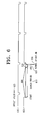
- FIG. 6 illustrates a method of controlling frame synchronization in accordance with the present invention.
- FIG. 7 is a flow chart showing a method of controlling frame synchronization in accordance with the present invention.
- FIG. 5 illustrates a constitution of a frame synchronization system in accordance with the present invention.
- a frame synchronization system includes a frame synchronization unit 550 and a frame control unit 500.
- the frame synchronization unit 550 inputs a frame synchronization start-signal 530 and a frame offset value 570 into the frame control unit 500.
- the frame control unit 500 receives the frame synchronization start-signal 530 from the frame synchronization unit 550 and then keeps the symbol count value constant, i.e. the value "0,” and then restarts symbol counting depending on the frame offset value 570 after receiving the frame offset value 570.
- FIG. 6 illustrates an exemplary embodiment of a method of controlling frame synchronization in accordance with the present invention.
- a method of controlling frame synchronization in accordance with the present invention will be described below with reference to FIG. 5 and FIG. 6.
- the frame control unit 500 starts symbol counting in response to a symbol counting signal 650.
- a beginning pulse of the symbol counting signal 650 is not coincident with a beginning pulse of an external signal 600, an incoming signal, so that frame synchronization is needed.
- the frame synchronization unit 550 inputs a frame synchronization signal 530 to the frame control unit 500 and at the same time estimates the frame offset value 620 during a search period 610.
- the frame control unit 500 keeps the symbol count value constant, i.e. the value "0" after receiving the frame synchronization start-signal 530. After that, the DAB receiver starts normal operation 630.
- a delay time ranging from at least one frame to at most two frames (average 1.5 frames) between estimation of the frame offset value and application of the estimated value. That is, it is possible to decrease the delay time by a time corresponding to one frame in comparison with the method in accordance with the related art. As a result, startup of the receiver can be faster, the total startup time is reduced and constitution of under-layer logic elements can be simplified.
- FIG. 7 illustrates a flow chart showing a method of controlling frame synchronization in accordance with the present invention.
- a frame control unit starts a symbol counter to count symbols, and operates to generate control signals (S710).
- a frame synchronization start-signal is input to the frame control unit (S730).
- the frame control unit After the frame control unit receives the frame synchronization start-signal, it initializes the value of the symbol counter and stops the symbol counter to count the symbols, so that the value of the symbol counter is kept null, i.e. the value "0" (S740).
- the frame synchronization unit inputs the frame synchronization start-signal to the frame control unit (S730), and then estimates a frame offset value (S750). In case that the estimated frame offset value is input to the frame control unit (S760), the frame control unit holds "0" as the value of the symbol counter for a time corresponding to the frame offset value, and then restarts the operation of the symbol counter (S780).
Landscapes
- Engineering & Computer Science (AREA)
- Signal Processing (AREA)
- Computer Networks & Wireless Communication (AREA)
- Multimedia (AREA)
- Synchronisation In Digital Transmission Systems (AREA)
- Circuits Of Receivers In General (AREA)
Applications Claiming Priority (1)
| Application Number | Priority Date | Filing Date | Title |
|---|---|---|---|
| KR1020050014196A KR100629506B1 (ko) | 2005-02-21 | 2005-02-21 | 유럽형 dab를 위한 프레임 동기 제어 방법 및 그 장치 |
Publications (2)
| Publication Number | Publication Date |
|---|---|
| EP1694019A1 true EP1694019A1 (de) | 2006-08-23 |
| EP1694019B1 EP1694019B1 (de) | 2013-05-29 |
Family
ID=36121451
Family Applications (1)
| Application Number | Title | Priority Date | Filing Date |
|---|---|---|---|
| EP06003273.7A Expired - Lifetime EP1694019B1 (de) | 2005-02-21 | 2006-02-17 | Verfahren und Vorrichtung zur Kontrolle der Rahmensynchronisierung in einem DAB-Empfänger |
Country Status (3)
| Country | Link |
|---|---|
| US (1) | US7756234B2 (de) |
| EP (1) | EP1694019B1 (de) |
| KR (1) | KR100629506B1 (de) |
Citations (1)
| Publication number | Priority date | Publication date | Assignee | Title |
|---|---|---|---|---|
| EP0901260A2 (de) * | 1997-05-12 | 1999-03-10 | Sony Corporation | Synchronisation von Rahmen und Symbolen in Mehrträgerempfängern |
Family Cites Families (4)
| Publication number | Priority date | Publication date | Assignee | Title |
|---|---|---|---|---|
| JP3764560B2 (ja) * | 1997-06-20 | 2006-04-12 | 株式会社ルネサステクノロジ | デジタル遅延回路及びデジタルpll回路 |
| JP4628591B2 (ja) * | 2001-06-07 | 2011-02-09 | 株式会社日立国際電気 | 拡散符号発生回路及び復調回路 |
| KR100833223B1 (ko) | 2001-07-11 | 2008-05-28 | 삼성전자주식회사 | 보호 구간을 이용해 심볼 타이밍 동기를 수행하는ofdm 수신 시스템 및 그 방법 |
| KR20050063155A (ko) | 2003-12-22 | 2005-06-28 | 엘지전자 주식회사 | Dmb 수신기에서의 전송 모드 검출 장치 및 방법 |
-
2005
- 2005-02-21 KR KR1020050014196A patent/KR100629506B1/ko not_active Expired - Fee Related
-
2006
- 2006-02-17 EP EP06003273.7A patent/EP1694019B1/de not_active Expired - Lifetime
- 2006-02-21 US US11/357,171 patent/US7756234B2/en not_active Expired - Fee Related
Patent Citations (1)
| Publication number | Priority date | Publication date | Assignee | Title |
|---|---|---|---|---|
| EP0901260A2 (de) * | 1997-05-12 | 1999-03-10 | Sony Corporation | Synchronisation von Rahmen und Symbolen in Mehrträgerempfängern |
Non-Patent Citations (1)
| Title |
|---|
| CHORNG-REN SHEU ET AL: "Joint symbol, frame, and carrier synchronization for Eureka 147 DAB system", IEEE 6TH. INTERNATIONAL CONFERENCE ON UNIVERSAL PERSONAL COMMUNICATIONS RECORD, vol. 2 CONF. 6, 12 October 1997 (1997-10-12), NEW YORK, IEEE, US, pages 693 - 697, XP010248797, ISBN: 0-7803-3777-8 * |
Also Published As
| Publication number | Publication date |
|---|---|
| EP1694019B1 (de) | 2013-05-29 |
| US20060188049A1 (en) | 2006-08-24 |
| KR20060093439A (ko) | 2006-08-25 |
| US7756234B2 (en) | 2010-07-13 |
| KR100629506B1 (ko) | 2006-09-28 |
Similar Documents
| Publication | Publication Date | Title |
|---|---|---|
| EP2051523A1 (de) | Empfänger | |
| WO2008014030A2 (en) | A receiver with a visual program guide for mobile television applications and method for creation | |
| US6925289B2 (en) | Broadcast receiver and channel scanning method | |
| US20090080545A1 (en) | Reducing data stream jitter during deinterleaving | |
| CN101646231A (zh) | Td-scdma系统中移动终端睡眠唤醒的定时同步恢复方法 | |
| EP1694019A1 (de) | Verfahren und System zur Kontrolle der Rahmensynchronisierung für den europäischen digitalen Tonrundfunk | |
| US7221715B2 (en) | Timing recovery device | |
| CN102045286A (zh) | 频偏估计方法及装置、主同步序列检测方法及装置 | |
| CN110794430A (zh) | 一种gps-l1c或bds-b1c频点卫星导航接收机冷启动方法 | |
| EP1071280B1 (de) | Empfängerschaltung | |
| WO2010036727A1 (en) | Fast stream switching | |
| US12149335B2 (en) | Method for improving audio acquisition time by nascent signal caching | |
| JP4812899B2 (ja) | 受信装置 | |
| US9893823B2 (en) | Seamless linking of multiple audio signals | |
| CN114598910B (zh) | 一种多路异源视频高精度时间同步回放控制方法 | |
| CN101213471A (zh) | 用于为组合的导频和数据信号跟踪提供优化接收机架构的系统和方法 | |
| US8238479B2 (en) | Synchronization and acquisition for mobile television reception | |
| WO2006040862A1 (ja) | デジタル放送受信装置 | |
| US7541884B2 (en) | Methods and apparatus for crystal oscillator drift estimation and compensation | |
| US20190327009A1 (en) | Method for improving digital radio mondiale (drm) acquisition time | |
| JP4547590B2 (ja) | 受信装置および方法、記録媒体、並びにプログラム | |
| JP2005507502A (ja) | 拡散スペクトラム信号収集方法および装置 | |
| KR20060022514A (ko) | 비동기식 이동통신시스템에서의 프레임 번호 결정 장치 및방법 | |
| CN121907652A (zh) | 一种基于fpga实现的多信道突发信号交织解调装置 | |
| JP2010124199A (ja) | デジタル放送受信装置 |
Legal Events
| Date | Code | Title | Description |
|---|---|---|---|
| PUAI | Public reference made under article 153(3) epc to a published international application that has entered the european phase |
Free format text: ORIGINAL CODE: 0009012 |
|
| AK | Designated contracting states |
Kind code of ref document: A1 Designated state(s): AT BE BG CH CY CZ DE DK EE ES FI FR GB GR HU IE IS IT LI LT LU LV MC NL PL PT RO SE SI SK TR |
|
| AX | Request for extension of the european patent |
Extension state: AL BA HR MK YU |
|
| 17P | Request for examination filed |
Effective date: 20061004 |
|
| 17Q | First examination report despatched |
Effective date: 20061117 |
|
| AKX | Designation fees paid |
Designated state(s): DE FR GB |
|
| RAP1 | Party data changed (applicant data changed or rights of an application transferred) |
Owner name: SAMSUNG ELECTRONICS CO., LTD. |
|
| GRAP | Despatch of communication of intention to grant a patent |
Free format text: ORIGINAL CODE: EPIDOSNIGR1 |
|
| GRAS | Grant fee paid |
Free format text: ORIGINAL CODE: EPIDOSNIGR3 |
|
| GRAA | (expected) grant |
Free format text: ORIGINAL CODE: 0009210 |
|
| AK | Designated contracting states |
Kind code of ref document: B1 Designated state(s): DE FR GB |
|
| REG | Reference to a national code |
Ref country code: GB Ref legal event code: FG4D |
|
| REG | Reference to a national code |
Ref country code: DE Ref legal event code: R096 Ref document number: 602006036520 Country of ref document: DE Effective date: 20130725 |
|
| PLBE | No opposition filed within time limit |
Free format text: ORIGINAL CODE: 0009261 |
|
| STAA | Information on the status of an ep patent application or granted ep patent |
Free format text: STATUS: NO OPPOSITION FILED WITHIN TIME LIMIT |
|
| 26N | No opposition filed |
Effective date: 20140303 |
|
| REG | Reference to a national code |
Ref country code: DE Ref legal event code: R097 Ref document number: 602006036520 Country of ref document: DE Effective date: 20140303 |
|
| REG | Reference to a national code |
Ref country code: FR Ref legal event code: PLFP Year of fee payment: 10 |
|
| PGFP | Annual fee paid to national office [announced via postgrant information from national office to epo] |
Ref country code: DE Payment date: 20150114 Year of fee payment: 10 |
|
| PGFP | Annual fee paid to national office [announced via postgrant information from national office to epo] |
Ref country code: FR Payment date: 20150115 Year of fee payment: 10 Ref country code: GB Payment date: 20150114 Year of fee payment: 10 |
|
| REG | Reference to a national code |
Ref country code: DE Ref legal event code: R119 Ref document number: 602006036520 Country of ref document: DE |
|
| GBPC | Gb: european patent ceased through non-payment of renewal fee |
Effective date: 20160217 |
|
| REG | Reference to a national code |
Ref country code: FR Ref legal event code: ST Effective date: 20161028 |
|
| PG25 | Lapsed in a contracting state [announced via postgrant information from national office to epo] |
Ref country code: DE Free format text: LAPSE BECAUSE OF NON-PAYMENT OF DUE FEES Effective date: 20160901 Ref country code: FR Free format text: LAPSE BECAUSE OF NON-PAYMENT OF DUE FEES Effective date: 20160229 Ref country code: GB Free format text: LAPSE BECAUSE OF NON-PAYMENT OF DUE FEES Effective date: 20160217 |