EP1710443A2 - Hydromechanisches Drucksignalfilterventil und LS-Steueranordnung - Google Patents
Hydromechanisches Drucksignalfilterventil und LS-Steueranordnung Download PDFInfo
- Publication number
- EP1710443A2 EP1710443A2 EP06007117A EP06007117A EP1710443A2 EP 1710443 A2 EP1710443 A2 EP 1710443A2 EP 06007117 A EP06007117 A EP 06007117A EP 06007117 A EP06007117 A EP 06007117A EP 1710443 A2 EP1710443 A2 EP 1710443A2
- Authority
- EP
- European Patent Office
- Prior art keywords
- filter
- valve
- pressure
- control
- throttle
- Prior art date
- Legal status (The legal status is an assumption and is not a legal conclusion. Google has not performed a legal analysis and makes no representation as to the accuracy of the status listed.)
- Granted
Links
- 238000001914 filtration Methods 0.000 title claims abstract description 5
- 238000006073 displacement reaction Methods 0.000 claims description 11
- 230000006835 compression Effects 0.000 claims description 9
- 238000007906 compression Methods 0.000 claims description 9
- 230000010355 oscillation Effects 0.000 claims description 8
- 230000002238 attenuated effect Effects 0.000 claims description 2
- 239000012530 fluid Substances 0.000 abstract description 3
- 238000013016 damping Methods 0.000 description 6
- 230000004044 response Effects 0.000 description 6
- 230000003111 delayed effect Effects 0.000 description 5
- 230000000694 effects Effects 0.000 description 4
- 238000011144 upstream manufacturing Methods 0.000 description 4
- 230000009467 reduction Effects 0.000 description 3
- 230000000903 blocking effect Effects 0.000 description 2
- 230000008859 change Effects 0.000 description 2
- 238000010586 diagram Methods 0.000 description 2
- 238000004088 simulation Methods 0.000 description 2
- 230000005540 biological transmission Effects 0.000 description 1
- 230000002542 deteriorative effect Effects 0.000 description 1
- 238000011161 development Methods 0.000 description 1
- 230000018109 developmental process Effects 0.000 description 1
- 230000004069 differentiation Effects 0.000 description 1
- 238000005516 engineering process Methods 0.000 description 1
- 210000003746 feather Anatomy 0.000 description 1
- 230000006872 improvement Effects 0.000 description 1
- 230000001151 other effect Effects 0.000 description 1
- 230000000630 rising effect Effects 0.000 description 1
- 230000008054 signal transmission Effects 0.000 description 1
- 230000036962 time dependent Effects 0.000 description 1
- 230000007704 transition Effects 0.000 description 1
Images


Classifications
-
- F—MECHANICAL ENGINEERING; LIGHTING; HEATING; WEAPONS; BLASTING
- F15—FLUID-PRESSURE ACTUATORS; HYDRAULICS OR PNEUMATICS IN GENERAL
- F15B—SYSTEMS ACTING BY MEANS OF FLUIDS IN GENERAL; FLUID-PRESSURE ACTUATORS, e.g. SERVOMOTORS; DETAILS OF FLUID-PRESSURE SYSTEMS, NOT OTHERWISE PROVIDED FOR
- F15B21/00—Common features of fluid actuator systems; Fluid-pressure actuator systems or details thereof, not covered by any other group of this subclass
- F15B21/008—Reduction of noise or vibration
-
- F—MECHANICAL ENGINEERING; LIGHTING; HEATING; WEAPONS; BLASTING
- F15—FLUID-PRESSURE ACTUATORS; HYDRAULICS OR PNEUMATICS IN GENERAL
- F15B—SYSTEMS ACTING BY MEANS OF FLUIDS IN GENERAL; FLUID-PRESSURE ACTUATORS, e.g. SERVOMOTORS; DETAILS OF FLUID-PRESSURE SYSTEMS, NOT OTHERWISE PROVIDED FOR
- F15B1/00—Installations or systems with accumulators; Supply reservoir or sump assemblies
- F15B1/02—Installations or systems with accumulators
- F15B1/021—Installations or systems with accumulators used for damping
-
- F—MECHANICAL ENGINEERING; LIGHTING; HEATING; WEAPONS; BLASTING
- F15—FLUID-PRESSURE ACTUATORS; HYDRAULICS OR PNEUMATICS IN GENERAL
- F15B—SYSTEMS ACTING BY MEANS OF FLUIDS IN GENERAL; FLUID-PRESSURE ACTUATORS, e.g. SERVOMOTORS; DETAILS OF FLUID-PRESSURE SYSTEMS, NOT OTHERWISE PROVIDED FOR
- F15B11/00—Servomotor systems without provision for follow-up action; Circuits therefor
- F15B11/16—Servomotor systems without provision for follow-up action; Circuits therefor with two or more servomotors
- F15B11/161—Servomotor systems without provision for follow-up action; Circuits therefor with two or more servomotors with sensing of servomotor demand or load
- F15B11/165—Servomotor systems without provision for follow-up action; Circuits therefor with two or more servomotors with sensing of servomotor demand or load for adjusting the pump output or bypass in response to demand
-
- F—MECHANICAL ENGINEERING; LIGHTING; HEATING; WEAPONS; BLASTING
- F15—FLUID-PRESSURE ACTUATORS; HYDRAULICS OR PNEUMATICS IN GENERAL
- F15B—SYSTEMS ACTING BY MEANS OF FLUIDS IN GENERAL; FLUID-PRESSURE ACTUATORS, e.g. SERVOMOTORS; DETAILS OF FLUID-PRESSURE SYSTEMS, NOT OTHERWISE PROVIDED FOR
- F15B13/00—Details of servomotor systems ; Valves for servomotor systems
- F15B13/02—Fluid distribution or supply devices characterised by their adaptation to the control of servomotors
- F15B13/04—Fluid distribution or supply devices characterised by their adaptation to the control of servomotors for use with a single servomotor
- F15B13/0401—Valve members; Fluid interconnections therefor
- F15B13/0407—Means for damping the valve member movement
-
- F—MECHANICAL ENGINEERING; LIGHTING; HEATING; WEAPONS; BLASTING
- F15—FLUID-PRESSURE ACTUATORS; HYDRAULICS OR PNEUMATICS IN GENERAL
- F15B—SYSTEMS ACTING BY MEANS OF FLUIDS IN GENERAL; FLUID-PRESSURE ACTUATORS, e.g. SERVOMOTORS; DETAILS OF FLUID-PRESSURE SYSTEMS, NOT OTHERWISE PROVIDED FOR
- F15B2211/00—Circuits for servomotor systems
- F15B2211/20—Fluid pressure source, e.g. accumulator or variable axial piston pump
- F15B2211/205—Systems with pumps
- F15B2211/2053—Type of pump
- F15B2211/20546—Type of pump variable capacity
- F15B2211/20553—Type of pump variable capacity with pilot circuit, e.g. for controlling a swash plate
-
- F—MECHANICAL ENGINEERING; LIGHTING; HEATING; WEAPONS; BLASTING
- F15—FLUID-PRESSURE ACTUATORS; HYDRAULICS OR PNEUMATICS IN GENERAL
- F15B—SYSTEMS ACTING BY MEANS OF FLUIDS IN GENERAL; FLUID-PRESSURE ACTUATORS, e.g. SERVOMOTORS; DETAILS OF FLUID-PRESSURE SYSTEMS, NOT OTHERWISE PROVIDED FOR
- F15B2211/00—Circuits for servomotor systems
- F15B2211/30—Directional control
- F15B2211/305—Directional control characterised by the type of valves
- F15B2211/30505—Non-return valves, i.e. check valves
-
- F—MECHANICAL ENGINEERING; LIGHTING; HEATING; WEAPONS; BLASTING
- F15—FLUID-PRESSURE ACTUATORS; HYDRAULICS OR PNEUMATICS IN GENERAL
- F15B—SYSTEMS ACTING BY MEANS OF FLUIDS IN GENERAL; FLUID-PRESSURE ACTUATORS, e.g. SERVOMOTORS; DETAILS OF FLUID-PRESSURE SYSTEMS, NOT OTHERWISE PROVIDED FOR
- F15B2211/00—Circuits for servomotor systems
- F15B2211/30—Directional control
- F15B2211/305—Directional control characterised by the type of valves
- F15B2211/30525—Directional control valves, e.g. 4/3-directional control valve
- F15B2211/3053—In combination with a pressure compensating valve
- F15B2211/30535—In combination with a pressure compensating valve the pressure compensating valve is arranged between pressure source and directional control valve
-
- F—MECHANICAL ENGINEERING; LIGHTING; HEATING; WEAPONS; BLASTING
- F15—FLUID-PRESSURE ACTUATORS; HYDRAULICS OR PNEUMATICS IN GENERAL
- F15B—SYSTEMS ACTING BY MEANS OF FLUIDS IN GENERAL; FLUID-PRESSURE ACTUATORS, e.g. SERVOMOTORS; DETAILS OF FLUID-PRESSURE SYSTEMS, NOT OTHERWISE PROVIDED FOR
- F15B2211/00—Circuits for servomotor systems
- F15B2211/30—Directional control
- F15B2211/31—Directional control characterised by the positions of the valve element
- F15B2211/3105—Neutral or centre positions
- F15B2211/3111—Neutral or centre positions the pump port being closed in the centre position, e.g. so-called closed centre
-
- F—MECHANICAL ENGINEERING; LIGHTING; HEATING; WEAPONS; BLASTING
- F15—FLUID-PRESSURE ACTUATORS; HYDRAULICS OR PNEUMATICS IN GENERAL
- F15B—SYSTEMS ACTING BY MEANS OF FLUIDS IN GENERAL; FLUID-PRESSURE ACTUATORS, e.g. SERVOMOTORS; DETAILS OF FLUID-PRESSURE SYSTEMS, NOT OTHERWISE PROVIDED FOR
- F15B2211/00—Circuits for servomotor systems
- F15B2211/30—Directional control
- F15B2211/31—Directional control characterised by the positions of the valve element
- F15B2211/3144—Directional control characterised by the positions of the valve element the positions being continuously variable, e.g. as realised by proportional valves
-
- F—MECHANICAL ENGINEERING; LIGHTING; HEATING; WEAPONS; BLASTING
- F15—FLUID-PRESSURE ACTUATORS; HYDRAULICS OR PNEUMATICS IN GENERAL
- F15B—SYSTEMS ACTING BY MEANS OF FLUIDS IN GENERAL; FLUID-PRESSURE ACTUATORS, e.g. SERVOMOTORS; DETAILS OF FLUID-PRESSURE SYSTEMS, NOT OTHERWISE PROVIDED FOR
- F15B2211/00—Circuits for servomotor systems
- F15B2211/30—Directional control
- F15B2211/315—Directional control characterised by the connections of the valve or valves in the circuit
- F15B2211/3157—Directional control characterised by the connections of the valve or valves in the circuit being connected to a pressure source, an output member and a return line
- F15B2211/31576—Directional control characterised by the connections of the valve or valves in the circuit being connected to a pressure source, an output member and a return line having a single pressure source and a single output member
-
- F—MECHANICAL ENGINEERING; LIGHTING; HEATING; WEAPONS; BLASTING
- F15—FLUID-PRESSURE ACTUATORS; HYDRAULICS OR PNEUMATICS IN GENERAL
- F15B—SYSTEMS ACTING BY MEANS OF FLUIDS IN GENERAL; FLUID-PRESSURE ACTUATORS, e.g. SERVOMOTORS; DETAILS OF FLUID-PRESSURE SYSTEMS, NOT OTHERWISE PROVIDED FOR
- F15B2211/00—Circuits for servomotor systems
- F15B2211/30—Directional control
- F15B2211/32—Directional control characterised by the type of actuation
- F15B2211/327—Directional control characterised by the type of actuation electrically or electronically
-
- F—MECHANICAL ENGINEERING; LIGHTING; HEATING; WEAPONS; BLASTING
- F15—FLUID-PRESSURE ACTUATORS; HYDRAULICS OR PNEUMATICS IN GENERAL
- F15B—SYSTEMS ACTING BY MEANS OF FLUIDS IN GENERAL; FLUID-PRESSURE ACTUATORS, e.g. SERVOMOTORS; DETAILS OF FLUID-PRESSURE SYSTEMS, NOT OTHERWISE PROVIDED FOR
- F15B2211/00—Circuits for servomotor systems
- F15B2211/40—Flow control
- F15B2211/405—Flow control characterised by the type of flow control means or valve
- F15B2211/40507—Flow control characterised by the type of flow control means or valve with constant throttles or orifices
-
- F—MECHANICAL ENGINEERING; LIGHTING; HEATING; WEAPONS; BLASTING
- F15—FLUID-PRESSURE ACTUATORS; HYDRAULICS OR PNEUMATICS IN GENERAL
- F15B—SYSTEMS ACTING BY MEANS OF FLUIDS IN GENERAL; FLUID-PRESSURE ACTUATORS, e.g. SERVOMOTORS; DETAILS OF FLUID-PRESSURE SYSTEMS, NOT OTHERWISE PROVIDED FOR
- F15B2211/00—Circuits for servomotor systems
- F15B2211/60—Circuit components or control therefor
- F15B2211/605—Load sensing circuits
- F15B2211/6051—Load sensing circuits having valve means between output member and the load sensing circuit
- F15B2211/6052—Load sensing circuits having valve means between output member and the load sensing circuit using check valves
-
- F—MECHANICAL ENGINEERING; LIGHTING; HEATING; WEAPONS; BLASTING
- F15—FLUID-PRESSURE ACTUATORS; HYDRAULICS OR PNEUMATICS IN GENERAL
- F15B—SYSTEMS ACTING BY MEANS OF FLUIDS IN GENERAL; FLUID-PRESSURE ACTUATORS, e.g. SERVOMOTORS; DETAILS OF FLUID-PRESSURE SYSTEMS, NOT OTHERWISE PROVIDED FOR
- F15B2211/00—Circuits for servomotor systems
- F15B2211/60—Circuit components or control therefor
- F15B2211/605—Load sensing circuits
- F15B2211/6051—Load sensing circuits having valve means between output member and the load sensing circuit
- F15B2211/6057—Load sensing circuits having valve means between output member and the load sensing circuit using directional control valves
-
- F—MECHANICAL ENGINEERING; LIGHTING; HEATING; WEAPONS; BLASTING
- F15—FLUID-PRESSURE ACTUATORS; HYDRAULICS OR PNEUMATICS IN GENERAL
- F15B—SYSTEMS ACTING BY MEANS OF FLUIDS IN GENERAL; FLUID-PRESSURE ACTUATORS, e.g. SERVOMOTORS; DETAILS OF FLUID-PRESSURE SYSTEMS, NOT OTHERWISE PROVIDED FOR
- F15B2211/00—Circuits for servomotor systems
- F15B2211/60—Circuit components or control therefor
- F15B2211/655—Methods of contamination control, i.e. methods of control of the cleanliness of circuit components or of the pressure fluid
-
- F—MECHANICAL ENGINEERING; LIGHTING; HEATING; WEAPONS; BLASTING
- F15—FLUID-PRESSURE ACTUATORS; HYDRAULICS OR PNEUMATICS IN GENERAL
- F15B—SYSTEMS ACTING BY MEANS OF FLUIDS IN GENERAL; FLUID-PRESSURE ACTUATORS, e.g. SERVOMOTORS; DETAILS OF FLUID-PRESSURE SYSTEMS, NOT OTHERWISE PROVIDED FOR
- F15B2211/00—Circuits for servomotor systems
- F15B2211/60—Circuit components or control therefor
- F15B2211/67—Methods for controlling pilot pressure
-
- F—MECHANICAL ENGINEERING; LIGHTING; HEATING; WEAPONS; BLASTING
- F15—FLUID-PRESSURE ACTUATORS; HYDRAULICS OR PNEUMATICS IN GENERAL
- F15B—SYSTEMS ACTING BY MEANS OF FLUIDS IN GENERAL; FLUID-PRESSURE ACTUATORS, e.g. SERVOMOTORS; DETAILS OF FLUID-PRESSURE SYSTEMS, NOT OTHERWISE PROVIDED FOR
- F15B2211/00—Circuits for servomotor systems
- F15B2211/80—Other types of control related to particular problems or conditions
- F15B2211/86—Control during or prevention of abnormal conditions
- F15B2211/8613—Control during or prevention of abnormal conditions the abnormal condition being oscillations
Definitions
- the invention relates to a hydromechanical filter valve for filtering pressure oscillations of certain frequency and / or amplitudes of a pressure signal applied in a control or pressure line.
- the invention further relates to an LS control arrangement.
- the present invention seeks to provide a hydromechanical filter valve, with the unwanted pressure fluctuations reliably can be eliminated.
- the invention is further based on the object to provide an LS control arrangement, are minimized in the low-frequency fluctuations of the pump pressure with low device complexity.
- the hydromechanical filter valve has a valve body which opens or closes a connection between an inlet and a drain and which is designed with two pressurized surfaces, one acting in the throttle direction and the other in the opening direction. Both surfaces are acted upon via a respective branching off from the inlet control line with the inlet pressure, wherein in the control line, which is acted upon in the throttle direction effective area with control oil, a valve device is provided, the control signals or their shares with the frequency range to be filtered or with greatly reduced amplitude lets through. In this case, signal components with a frequency above a cutoff frequency are not transmitted or only attenuated and signal components with a frequency below the cutoff frequency are essentially transmitted.
- the invention is based on the fact that the voltage applied in the inlet pressure signal is present at a control edge of the filter valve and simultaneously passed to its two control surfaces, wherein in the opening direction, the pressure signal is substantially unchanged, while in the throttle direction by the arranged in the control line valve means only pressure signals acting in the frequency range to be filtered or below act. That is, via the valve device in the control line pressure signals are locked at a relatively high frequency, so that it practically acts as a low-pass filter. As a result, at lower frequencies or rates of pressure rise or decay on both sides of the valve body, the same forces act and remain in their home position (minimum flow or maximum flow depending on design).
- the pressure fluctuations are relatively high-frequency, they are filtered via the valve device in the control line, that the relatively high-frequency component of the pressure signal acts only on the other control surface in the opening direction - the valve body is then moved accordingly in the opening direction and the high-frequency pressure signal pass through. Comparatively low-frequency pressure fluctuations are reliably blocked via the filter valve, however.
- the effective as a low-pass filter, arranged in the control line valve means is designed by a filter choke and a series-connected filter volume.
- the valve body of the filter valve is preferably biased by a spring in the direction of its closed position.
- the filter valve is designed with negative coverage, so that the valve body never fully closes, so that very slow pressure changes that do not lead to unwanted vibrations in the system, the valve can happen. That is, the filter valve according to the invention is designed not as a high-pass filter but as a band-stop filter, with very slow pressure fluctuations and high-frequency pressure fluctuations are transmitted while a harmful frequency range lying in between is blocked.
- This frequency range is often in the range between 5 and 20 hertz in LS control arrangements in mobile technology.
- the valve device preferably has a variable filter throttle, so that the throttling effect becomes greater with increasing vibration.
- the filter choke In the open position, the filter choke has a large diameter. In the throttle position this has a small diameter. For stronger vibrations, therefore, the slide remains longer in a throttle position.
- the valve body of the filter valve is biased by a compression spring in the opening direction, so that the filter valve is turned on in the rest position and a strong throttling of each pressure signal is avoided and only at a certain dynamics, a throttling is made.
- each individual metering orifice assigned to a consumer is assigned an individual pressure balance.
- the valve according to the invention is needed only once, in the LS line between the valve block and the pump. Not every valve disk needs to be assigned a separate filter valve.
- the pump for supplying pressure medium to the consumer can be designed as a variable displacement pump or as a fixed displacement pump with bypass pressure compensator.
- FIG. 1 shows a circuit diagram of an LS control arrangement 1 of a mobile implement, for example a tractor.
- a mobile control block This has a plurality of consumers 2, which are supplied via a mobile control block, each with a trained according to Figure 1 valve disc by a variable displacement pump 4 with pressure medium.
- a variable displacement pump 4 with pressure medium.
- FIG. 1 shows only one consumer, which is for example a lifting cylinder 2 of a hoist.
- the direction of movement and speed of the hydraulic cylinder 2 is adjusted by means of a proportionally adjustable directional control valve 6, the speed part of which forms a metering orifice 8, via which the pressure medium volume flow to the consumer 2 is set.
- the hydraulic cylinder 2 is shown Embodiment designed as a differential cylinder and is divided by a piston 10 in a bottom-side cylinder chamber 12 and a penetrated by a piston rod annular space 14.
- a working port A of the directional control valve 6 is connected via a feed line 16 to the cylinder chamber 12 and a working port B of the directional control valve 6 via a return line 18 to the annular space 14 of the hydraulic cylinder 2.
- a pressure connection of the variable displacement pump 4 is connected via a supply line 20 to an input port P of the directional control valve whose tank port T opens into a tank 24 via a discharge line 22.
- an individual pressure compensator 26 is arranged, which is acted upon in the closing direction via a control line 28 from the pressure upstream of the metering orifice 8 and in the opening direction of the pressure in a LS line 30.
- a control line 28 from the pressure upstream of the metering orifice 8 and in the opening direction of the pressure in a LS line 30.
- the individual pressure compensator 26 is further acted upon in the opening direction by the force of a spring 32.
- the individual pressure compensator 26 forms, together with the metering orifice 8, a flow regulator, via which the pressure drop across the inlet metering orifice 8 can be kept constant independently of the load pressure.
- Such LS control arrangements with upstream pressure compensator are known from the prior art, so that further embodiments are dispensable.
- a check valve 31 is provided, which opens in the direction of the directional control valve 6.
- the ports P, A, B of the directional control valve 6 are shut off and the LS line 30 is connected to the drain line 22, so that it is depressurized.
- the directional control valve 6 in one of his (a) marked positions of the pressure port P is connected to the working port B and the working port A to the tank port T, so that pressure medium depending on the setting of the metering orifice 8 conveyed into the annular space 14 and due to the retraction movement of the piston 10 the cylinder chamber 12 is displaced to the tank 24 out.
- the pressure medium is conveyed via the metering orifice into the cylinder chamber 12 and displaced out of the annular space 14 to the tank 24.
- the LS line 30 leads to a pump controller 34, via which the variable displacement pump 4 is controlled such that the pump pressure in the supply line 20 is always above a predetermined pressure difference .DELTA.p above the highest load pressure in the LS line 30 (LS system).
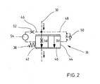
- a hydromechanical filter valve 36 is arranged in the LS line, the structure of which is explained with reference to FIG.
- This filter valve 36 is designed as a continuously adjustable valve with negative overlap and biased by a compression spring 38 in the direction of a basic position (a), in which the connection between the inlet side of the filter valve 36 and the drain side (bottom in Figure 2) is still slightly open, so that Control oil from the pump controller 34 and from this back to the tank 24 can flow.
- a slider 40 of the filter valve 36 is designed with two control surfaces 42, 44, wherein the control surface 42 in terms of a reduction of the flow cross-section and the control surface 44 in terms of increasing the flow cross-section of the filter valve 36 is effective.
- a throttle check valve 50 is arranged, which ensures that the filter valve 36 is still kept open after a rapid increase in pressure for a short time, so that some tax oil is allowed to drain.
- a filter choke 52 and a filter volume 54 are arranged in series with each other.
- the filter choke 52 and the filter volume 54 together form a low-pass filter whose frequency response u.a. depends on the diameter of the filter throttle 52 and the size of the filter volume 54.
- the remaining at rest negative coverage together with the hydraulic capacity on the outlet side of the filter valve 36 is a low-pass filter.
- the size of the negative coverage can determine which frequencies the filter valve can happen in any case. In this case, however, care must be taken that this frequency does not overlap with the blocking frequency specified via the filter throttle 52 and the filter volume 54, since otherwise the filter valve 36 is ineffective.
- the filter valve 36 thus represents a band rejection filter that allows lower and higher frequencies to pass, but blocks a medium frequency range, for example 5 to 20 Hertz. Strictly speaking, a certain range of pressure rise rates are blocked. Very slow and very fast rising pressure signals are little affected while a certain range of pressure rise rates are blocked by the filter valve 36.
- the rate of pressure rise together with a certain amplitude gives a frequency - In this respect pressure increase rate and frequency are basically proportional to each other, although the factor depends on the amplitude. In the above embodiments, therefore, for the sake of simplicity of frequencies is spoken.
- undesirable frequencies can be filtered out by the filter valve according to the invention selectively, without deteriorating the dynamics of the response when switching valves that are used to control the hydraulic consumers.
- the filter choke 52 and the associated filter volume 54 By suitable design of the filter choke 52 and the associated filter volume 54, the desired filtered frequency range can be easily adapted to the existing operating conditions.
- the pressure differences between the two control surfaces 42, 44 may be relatively low.
- the forces acting in the opening direction are correspondingly small.
- act on the control edge of the filter valve 36 flow forces in the closing direction. If their proportion is too large, the filter valve can not open far enough and thus not work properly.
- the slide diameter should therefore not fall below a certain minimum level to ensure proper functioning.
- the influence of the slider friction on the valve function becomes smaller, the larger its diameter.
- An upper limit for the slide diameter is given by the fact that the slide displaces control oil in the direction of an end face even during its movement (depending on the direction of movement).
- this control oil displacement itself leads to a pressure increase on the corresponding front side and could thus falsify the operation of the valve.
- a slide diameter of about 8 mm has been found to be the preferred measure.
- FIG. 3 shows the time-dependent course of the LS pressure and the pump pressure (pressure in the feed line 20) in a conventional system. It can be seen that due to the variations in the load pressure in the LS line 30, the pump pressure is subject to considerable fluctuations, which lead to mechanical vibrations of hydraulic consumers.
- the pressure fluctuations in the LS line 30 shown in FIG 4 can be reduced to a minimum, with only high-frequency oscillations reach the pump controller 34, which are harmless to the function of the LS control arrangement. Accordingly, in the supply line 20, a pump pressure, the pressure fluctuations have a much lower amplitude of the harmful frequency than in the prior art - such pressure fluctuations are harmless and affect the control of the consumer 2 practically not.
- Fig. 5 shows a hydrodynamic filter valve 136 according to a second embodiment of the present invention, which is usable instead of the filter valve 36 in the LS control arrangement of Fig. 1.
- This filter valve 136 is designed as a continuously adjustable valve and biased by a compression spring 138 in the direction of a rest position (a), in which the connection between the inlet side of the filter valve 136 and the drain side (bottom in Figure 5) is opened, so that Control oil from the pump controller 34 and from this back to the tank 24 can flow.
- a rest position
- pressure fluid can only throttled flow from the pump regulator and from this back to the tank.
- the slide 140 of the filter valve 136 is designed with two control surfaces 142, 144, wherein the control surface 142 in terms of increasing the flow cross-section and the control surface 144 in the sense of reducing the flow cross-section of the filter valve 136 is effective.
- the pressure in the LS line 30 acts without damping or throttling.
- a filter throttle 152 and a filter volume 154 are arranged in series with each other.
- a check valve 156 which opens toward the control surface 144 is provided, in the open position of which control oil can be supplied from the LS line 30 via the filter volume 154 of the control surface 144.
- the filter throttle 152 and the check valve 156 together form a throttle check valve.
- the filter choke 152 and the filter volume 154 together form a low-pass filter whose frequency response depends on the diameter of the filter choke 152 and the size of the filter volume 154.
- control oil is directed to the control surface 142 via the control line 148 and to the control surface 144 via the opened check valve 156 as the pressure increases, so that the spool 144 is initially in the Rest position (a) remains.
- control oil is reduced in the limited by the control surface 144 pressure chamber on the filter volume 154 and the filter throttle 152 only delayed to the LS line 30, while control oil in the control line 148 unchanged on the control surface 142nd acts.
- the slider 140 is displaced against the force of the spring 138 in the throttle direction (b) in its throttle position.
- An LS signal with relative high frequencies in the LS line 30 is thus forwarded by the filter valve 136 to the pump controller 34 back only throttled.
- the slider 140 After a decay of the vibrations that contain frequency components above the cutoff frequency, in the LS line 30, the slider 140 is moved by the compression spring 138 back into the rest position (a).
- the filter valve 136 according to the second embodiment has a notch filter effect.
- Fig. 6 shows a filter valve 236 according to the third embodiment, which differs from the filter valve 136 according to the second embodiment by a variable throttling of the control oil volume flow from the filter volume 254 to the control line 246.
- the hydrodynamic filter valve 236 according to the third embodiment of the present invention is used instead of the filter valve 36 in the LS control arrangement of FIG. 1 and is also designed as a continuously adjustable valve and is biased by a compression spring 238 in the direction of a rest position (a) in which the connection between the inlet side of the filter valve 236 and the Outflow side (bottom in Figure 6) is open, so that control oil from the pump controller 34 and from this back to the tank 24 can flow.
- the slider 240 of the filter valve 236 is designed with two control surfaces 242, 244, wherein the control surface 242 in terms of increasing the flow cross-section and the control surface 244 in terms of reducing the flow cross-section of the filter valve 236 is effective.
- the pressure in the LS line 30 acts without damping or throttling.
- a check valve 256 and a filter volume 254 are arranged in series. Between the inlet of the filter valve 236 and the filter volume 254 is a variable filter throttle, which is determined by a control edge and in Fig. 6 by a filter choke 252 a large diameter and a filter choke 252 b is shown with small diameter, provided.
- the variable filter throttle 252a, 252b is arranged in the slider 240 and is switched in response to the position of the slider 240.
- the large-diameter throttle 252a is switched to the rest position (a); the throttle diameter is reduced in the throttle position (b) to the small diameter throttle 252b.
- the check valve 256 opens to the control surface 244, wherein in its open position, the pressure in the LS line 30 via the filter volume 254 rests against the control surface 144.
- the variable filter choke 252a, 252b and the filter volume 254 together form a low-pass filter whose frequency response depends on the diameter of the variable filter choke 252a, 252b and thus on the slide position of the filter valve and on the size of the filter volume 254.
- control oil is directed to the control surface 242 via the control line 248 and the control surface 244 via the opened check valve 256 with increasing pressure, so that the slider 240 in the first Rest position (a) remains.
- the pressure in the through the control surface 244 limited pressure chamber degraded relatively slowly over the filter choke 252 a large diameter, while the control oil in the control line 248 acts unchanged on the control surface 242.
- the slider 240 is displaced against the force of the spring 238 in the throttle direction in its throttle position (b).
- An LS signal with relatively high frequencies in the LS line 30 is thus forwarded by the filter valve 136 to the pump controller 34 only throttled.
- the pressure difference across the filter choke is still higher due to the faster pressure change, so that the slider 240 is further displaced in the throttle direction.
- the control edge in the filter valve reduces the throttle diameter, so that a smaller filter throttle is effective. It is achieved an improved filter effect.
- FIG. 7 shows a simulation without a vibration throttle
- FIGS. 8 and 9 are simulations with a filter valve according to the second embodiment demonstrate.
- Fig. 8 there is a slide damping of 50 Ns / m, at the still disturbing low-frequency vibrations in the LS pressure and pump pressure are present, while in Fig. 9, a slide damping of 500 Ns / m is present, causing annoying low-frequency oscillations no longer available.
- variable displacement pump 4 In the embodiment of the present invention shown in Figure 1, a variable displacement pump 4 is provided. In principle, instead of the variable displacement pump 4, it is also possible to use a constant displacement pump with a bypass pressure compensator, with the LS pressure then being applied to the inlet pressure compensator.
- the filter valve 36 can also be used in LUDV systems (load pressure independent flow behavior), in which the individual pressure compensator of the metering orifice is connected downstream and is acted upon in the opening direction of the highest load pressure of the consumer.
- the filter valve can be used in all hydraulic systems in which low-frequency vibrations are to be eliminated, as long as it is installed in a line that serves only to forward pressure signals. Due to the strong throttling of the pressure signal in case of unwanted Vibrations can not be used in pipes through which larger volume flows flow. The valve can only influence the signal transmission, not the line transmission.
- a filter valve for filtering pressure fluctuations of certain frequency and / or amplitude of a pressure signal and designed with such a filter valve LS control arrangement.
- the filter valve has a valve body with two oppositely effective control surfaces, both of which can be acted upon via a control line with the inlet pressure.
- a valve device with a low-pass filter function is arranged, via which higher-frequency control signals can be filtered out.
Landscapes
- Engineering & Computer Science (AREA)
- Physics & Mathematics (AREA)
- Fluid Mechanics (AREA)
- Mechanical Engineering (AREA)
- General Engineering & Computer Science (AREA)
- Chemical & Material Sciences (AREA)
- Analytical Chemistry (AREA)
- Fluid-Pressure Circuits (AREA)
- Control Of Fluid Pressure (AREA)
- Glass Compositions (AREA)
- Developing Agents For Electrophotography (AREA)
- Transition And Organic Metals Composition Catalysts For Addition Polymerization (AREA)
Abstract
Description
- Die Erfindung betrifft ein hydromechanisches Filterventil zur Filterung von Druckschwingungen bestimmter Frequenz und/oder Amplituden eines Drucksignals, das in einer Steuer- oder Druckleitung anliegt. Die Erfindung betrifft des Weiteren eine LS-Steueranordnung.
- Insbesondere bei Load-Sensing-Systemen (LS-Systeme) können in der LS-Leitung, über die der höchste Lastdruck mehrerer Verbraucher abgegriffen und zu einem Pumpenregler geführt wird, Druckschwingungen auftreten, die dann in Schwingungen des Pumpendrucks resultieren. Es zeigte sich, dass insbesondere in der Mobilhydraulik die niederfrequenten Schwingungen zu mechanischen Schwingungen von hydraulischen Verbrauchern führen können und daher nicht akzeptabel sind.
- Bei LS-Systemen können derartige Druckschwingungen durch Veränderung an den Ventilen oder Pumpenreglern verringert werden, wobei beispielsweise die Federn der Individualdruckwaagen des LS-Systems so ausgelegt werden, dass die unerwünschten Schwingungen verringert werden. Es sind auch Lösungen bekannt, bei denen in der LS-Leitung ein Drosselrückschlagventil oder ähnliches eingebaut wurde; es zeigte sich jedoch, dass derartige Lösungen eine Verbesserung nur in bestimmten Arbeitspunkten ermöglichen, im Übrigen jedoch unwirksam sind.
- Demgegenüber liegt der Erfindung die Aufgabe zugrunde, ein hydromechanisches Filterventil zu schaffen, mit dem unerwünschte Druckschwankungen zuverlässig beseitigt werden können. Der Erfindung liegt des weiteren die Aufgabe zugrunde, eine LS-Steueranordnung zu schaffen, bei der niederfrequente Schwankungen des Pumpendrucks mit geringem vorrichtungstechnischen Aufwand minimiert sind.
- Diese Aufgabe wird hinsichtlich des hydraulischen Filterventils durch die Merkmale des Patentanspruches 1 und hinsichtlich der LS-Steueranordnung durch die Merkmale des Patentanspruches 14 gelöst.
- Erfindungsgemäß hat das hydromechanische Filterventil einen eine Verbindung zwischen einem Zulauf und einem Ablauf auf- bzw. zusteuernden Ventilkörper, der mit zwei druckbeaufschlagten Flächen ausgeführt ist, wobei eine in Drosselrichtung und die andere in Öffnungsrichtung wirkt. Beide Flächen werden über eine jeweils vom Zulauf abzweigende Steuerleitung mit dem Zulaufdruck beaufschlagt, wobei in der Steuerleitung, über die die in Drosselrichtung wirksame Fläche mit Steueröl beaufschlagt wird, eine Ventileinrichtung vorgesehen ist, die Steuersignale oder deren Anteile mit dem zu filternden Frequenzbereich nicht oder mit stark verringerter Amplitude durchlässt. Dabei werden Signalanteile mit einer Frequenz oberhalb einer Grenzfrequenz nicht oder nur abgeschwächt durchgelassen und Signalanteile mit einer Frequenz unterhalb der Grenzfrequenz im Wesentlichen durchgelassen.
- Demzufolge basiert die Erfindung darauf, dass das im Zulauf anliegende Drucksignal zum einen an einer Steuerkante des Filterventils ansteht und gleichzeitig auf seine beiden Steuerflächen geleitet wird, wobei in Öffnungsrichtung das Drucksignal im wesentlichen unverändert wirksam ist, während in Drosselrichtung durch die in der Steuerleitung angeordnete Ventileinrichtung nur Drucksignale wirken, die im zu filternden Frequenzbereich oder darunter liegen. Das heißt, über die Ventileinrichtung in der Steuerleitung werden Drucksignale mit einer relativ hohen Frequenz gesperrt, so dass diese praktisch als Tiefpassfilter wirkt. Demzufolge wirken bei niedrigeren Frequenzen bzw. Druckanstiegsgeschwindigkeiten bzw. Druckabbaugeschwindigkeiten auf beiden Seiten des Ventilkörpers die gleichen Kräfte und dieser verbleibt in seiner Grundposition (minimaler Durchfluss bzw. maximaler Durchfluss je nach Ausführung). Für den Fall, dass die Druckschwankungen relativ hochfrequent sind, so werden diese über die Ventileinrichtung in der Steuerleitung gefiltert, dass der relativ hochfrequente Anteil des Drucksignals nur auf die andere Steuerfläche in Öffnungsrichtung wirkt - der Ventilkörper wird dann entsprechend in Öffnungsrichtung verschoben und das hochfrequente Drucksignal durchgelassen. Vergleichsweise niederfrequente Druckschwankungen werden über das Filterventil dagegen zuverlässig gesperrt. Durch Einsatz eines derartigen hydromechanischen Filterventils in eine LS-Leitung einer LS-Steueranordnung können Schwankungen des Pumpendrucks im schädlichen Bereich zuverlässig verhindert werden.
- Bei einem besonders bevorzugten Ausführungsbeispiel ist die als Tiefpassfilter wirksame, in der Steuerleitung angeordnete Ventileinrichtung durch eine Filterdrossel und ein dazu in Reihe geschaltetes Filtervolumen ausgeführt. Durch Auslegung des Drosseldurchmessers und des Filtervolumens kann dabei der Frequenzgang dieses Tiefpassfilters an die vorliegenden Betriebsbedingungen angepasst werden.
- Um das Filterventil auch nach einem schnellen Druckanstieg noch für eine kurze Zeit offen zu halten, kann in der anderen, zur in Öffnungsrichtung wirksamen Steuerfläche führenden Steuerleitung ein Drosselrückschlagventil vorgesehen werden.
- Der Ventilkörper des Filterventils wird vorzugsweise über eine Feder in Richtung seiner Schließposition vorgespannt.
- Erfindungsgemäß wird es bevorzugt, wenn das Filterventil mit negativer Überdeckung ausgeführt ist, so dass der Ventilkörper niemals vollständig schließt, so dass sehr langsame Druckänderungen, die nicht zu unerwünschten Schwingungen im System führen, das Ventil passieren können. D.h., das erfindungsgemäße Filterventil ist nicht als Hochpass sondern als Bandsperre ausgeführt, wobei sehr langsame Druckschwankungen und hochfrequente Druckschwankungen durchgelassen werden, während ein dazwischen liegender schädlicher Frequenzbereich gesperrt ist.
- Dieser Frequenzbereich liegt bei LS-Steueranordnungen in der Mobiltechnik häufig im Bereich zwischen 5 und 20 Hertz.
- Die Ventileinrichtung hat vorzugsweise eine variable Filterdrossel, so dass die Drosselwirkung mit stärker werdender Schwingung größer wird. In der Öffnungsstellung weist die Filterdrossel einen großen Durchmesser auf. In der Drosselstellung hat diese einen kleinen Durchmesser. Bei stärkeren Schwingungen bleibt daher der Schieber länger in einer Drosselstellung.
- Entsprechend einer anderen Ausgestaltung der Erfindung ist der Ventilkörper des Filterventils über eine Druckfeder in Öffnungsrichtung vorgespannt, so dass das Filterventil in der Ruhestellung aufgesteuert ist und eine starke Androsselung jedes Drucksignals vermieden wird und erst bei einer bestimmten Dynamik eine Androsselung vorgenommen wird.
- In dem Fall, in dem die LS-Steueranordnung zur Ansteuerung mehrerer Verbraucher vorgesehen ist, wird vorzugsweise jeder einem Verbraucher zugeordneten Zumessblende eine Individualdruckwaage zugeordnet. Das erfindungsgemäße Ventil wird jedoch nur einmal benötigt, in der LS-Leitung zwischen Ventilblock und Pumpe. Es muss nicht jeder Ventilscheibe ein separates Filterventil zugeordnet werden.
- Die Pumpe zur Druckmittelversorgung der Verbraucher kann als Verstellpumpe oder als Konstantpumpe mit Bypassdruckwaage ausgeführt sein.
- Sonstige vorteilhafte Weiterbildungen der Erfindung sind Gegenstand weiterer Unteransprüche.
- Im Folgenden wird ein bevorzugtes Ausführungsbeispiel der Erfindung anhand schematischer Zeichnungen näher erläutert. Es zeigen:
- Figur 1 ein Schaltbild einer LS-Steueranordnung mit einem ersten Ausführungsbeispiel eines hydromechanischen Filterventils;
- Figur 2 das hydromechanische Filterventil aus Figur 1;
- Figur 3 Druckschwankungen des Pumpendrucks und des Lastdrucks bei einer herkömmlichen LS-Steueranordnung;
- Figur 4 Schwankungen des Pumpendrucks und des LS-Drucks bei einer erfindungsgemäßen LS-Steueranordnung entsprechend Fig. 1;
- Fig. 5 ein zweites Ausführungsbeispiel eines hydromechanischen Filterventils;
- Fig. 6 ein drittes Ausführungsbeispiel eines hydromechanischen Filterventils;
- Figur 7 Druckschwankungen des Pumpendrucks und des LS-Drucks bei einer herkömmlichen LS-Steueranordnung;
- Figur 8 Schwankungen des Pumpendrucks und des LS-Drucks bei einer erfindungsgemäßen LS-Steueranordnung nach Fig. 6 bei geringer Schieberdämpfung; und
- Figur 9 Schwankungen des Pumpendrucks und des LS-Drucks bei einer erfindungsgemäßen LS-Steueranordnung nach Fig. 6 bei starker Schieberdämpfung.
- Figur 1 zeigt ein Schaltschema einer LS-Steueranordnung 1 eines mobilen Arbeitsgerätes, beispielsweise eines Traktors. Dieser hat eine Vielzahl von Verbrauchern 2, die über einen Mobilsteuerblock mit jeweils einer nach Figur 1 ausgebildeten Ventilscheibe von einer Verstellpumpe 4 mit Druckmittel versorgt werden. In der Darstellung gemäß Figur 1 ist lediglich ein Verbraucher dargestellt, der beispielsweise ein Hubzylinder 2 eines Hubwerks ist. Die Bewegungsrichtung und -geschwindigkeit des Hydraulikzylinders 2 wird mittels eines proportional verstellbaren Wegeventils 6 eingestellt, dessen Geschwindigkeitsteil eine Zumessblende 8 ausbildet, über die der Druckmittelvolumenstrom zum Verbraucher 2 eingestellt wird. Der Hydraulikzylinder 2 ist beim dargestellten Ausführungsbeispiel als Differentialzylinder ausgeführt und ist durch einen Kolben 10 in einen bodenseitigen Zylinderraum 12 und eine von einer Kolbenstange durchsetzten Ringraum 14 unterteilt. Ein Arbeitsanschluss A des Wegeventils 6 ist über eine Vorlaufleitung 16 mit dem Zylinderraum 12 und ein Arbeitsanschluss B des Wegeventils 6 über eine Rücklaufleitung 18 mit dem Ringraum 14 des Hydraulikzylinders 2 verbunden. Ein Druckanschluss der Verstellpumpe 4 ist über eine Zulaufleitung 20 mit einem Eingangsanschluss P des Wegeventils verbunden, dessen Tankanschluss T über eine Ablaufleitung 22 in einen Tank 24 einmündet. In der Zulaufleitung 20 ist eine Individualdruckwaage 26 angeordnet, die in Schließrichtung über eine Steuerleitung 28 vom Druck stromaufwärts der Zumessblende 8 und in Öffnungsrichtung vom Druck in einer LS-Leitung 30 beaufschlagt ist. Über diese LS-Leitung 30 wird der Lastdruck des Verbrauchers 2 abgegriffen. Die Individualdruckwaage 26 ist des Weiteren in Öffnungsrichtung von der Kraft einer Feder 32 beaufschlagt. Die Individualdruckwaage 26 bildet gemeinsam mit der Zumessblende 8 einen Stromregler aus, über den der Druckabfall über der Zulaufmessblende 8 unabhängig vom Lastdruck konstant gehalten werden kann. Derartige LS-Steueranordnungen mit vorgeschalteter Druckwaage sind aus dem Stand der Technik bekannt, so dass weitere Ausführungen entbehrlich sind.
- Im Bereich zwischen der Individualdruckwaage 26 und dem proportional verstellbaren Wegeventil 6 ist ein Rückschlagventil 31 vorgesehen, das in Richtung zum Wegeventil 6 öffnet. In der dargestellten federvorgespannten Grundposition (0) sind die Anschlüsse P, A, B des Wegeventils 6 abgesperrt und die LS-Leitung 30 mit der Ablaufleitung 22 verbunden, so dass diese druckentlastet wird. Bei Verschieben des Wegeventils 6 in eine seiner mit (a) gekennzeichneten Positionen wird der Druckanschluss P mit dem Arbeitsanschluss B und der Arbeitsanschluss A mit dem Tankanschluss T verbunden, so dass Druckmittel in Abhängigkeit von der Einstellung der Zumessblende 8 in den Ringraum 14 gefördert und aufgrund der Einfahrbewegung des Kolbens 10 aus dem Zylinderraum 12 zum Tank 24 hin verdrängt wird. Bei Einstellung des Wegeventils 6 in eine seiner mit (b) gekennzeichneten Positionen wird entsprechend das Druckmittel über die Zumessblende in den Zylinderraum 12 gefördert und aus dem Ringraum 14 zum Tank 24 hin verdrängt.
- Die LS-Leitung 30 führt zu einem Pumpenregler 34, über den die Verstellpumpe 4 derart geregelt wird, dass der Pumpendruck in der Zulaufleitung 20 stets über eine vorbestimmte Druckdifferenz Δp über dem höchsten Lastdruck in der LS-Leitung 30 liegt (LS-System).
- Wie bereits eingangs erwähnt, kann es insbesondere bei Anwendungen in der Mobilhydraulik zu Druckschwankungen in der LS-Leitung 30 kommen, die in Druckschwankungen des Pumpendrucks resultieren, wobei insbesondere die Frequenzen im Bereich zwischen 5 und 20 Hertz schädlich sind und zu Unstetigkeiten in der Ansteuerung des oder der Verbraucher führen können. Zur Minimierung derartiger unerwünschter Druckschwankungen ist in der LS-Leitung ein hydromechanisches Filterventil 36 entsprechend dem ersten Ausführungsbeispiel angeordnet, dessen Aufbau anhand Figur 2 erläutert wird.
- Dieses Filterventil 36 ist als stetig verstellbares Ventil mit negativer Überdeckung ausgeführt und über eine Druckfeder 38 in Richtung einer Grundposition (a) vorgespannt, in der die Verbindung zwischen der Zulaufseite des Filterventils 36 und der Ablaufseite (unten in Figur 2) noch etwas geöffnet ist, so dass Steueröl vom Pumpenregler 34 und von diesem zurück zum Tank 24 strömen kann. Ein Schieber 40 des Filterventils 36 ist mit zwei Steuerflächen 42, 44 ausgeführt, wobei die Steuerfläche 42 im Sinne einer Verringerung des Durchströmungsquerschnittes und die Steuerfläche 44 im Sinne einer Vergrößerung des Durchströmungsquerschnittes des Filterventils 36 wirksam ist. Vom Zulauf des Filterventils 36 zweigt zu einem von der Steuerfläche 42 begrenzten Steuerraum eine Steuerleitung 46 und zu einem von der Steuerfläche 44 begrenzten Steuerraum eine Steuerleitung 48 ab, d.h. an der Steuerkante des Schiebers 40 und an den beiden Steuerflächen 42, 44 liegt im Prinzip der Zulaufdruck 30 an. In der der Steuerfläche 44 zugeordneten Steuerleitung 48 ist ein Drosselrückschlagventil 50 angeordnet, das dafür sorgt, dass das Filterventil 36 nach einem schnellen Druckanstieg noch kurze Zeit offen gehalten wird, so dass noch etwas Steueröl zum Ablauf durchgelassen wird.
- In der der Steuerfläche 42 zugeordneten Steuerleitung 46 sind eine Filterdrossel 52 und ein Filtervolumen 54 in Reihe zueinander angeordnet. Die Filterdrossel 52 und das Filtervolumen 54 bilden zusammen ein Tiefpassfilter, dessen Frequenzgang u.a. vom Durchmesser der Filterdrossel 52 und der Größe des Filtervolumens 54 abhängt. Je kleiner der Durchmesser der Filterdrossel 52 und je größer das Volumen des Filtervolumens 54 ist, desto tiefer muss eine Frequenz sein, um auf die Federseite (Steuerfläche 42) des Filterventils 36 zu gelangen. D.h. durch die Filterdrossel 52 und das Filtervolumen 54 werden vergleichsweise hohe Frequenzen des LS-Signals ausgefiltert.
- In Öffnungsrichtung wirkt auf den Schieber 40 des Filterventils 36 das LS-Signal praktisch unverändert. In Schließrichtung wird das LS-Signal mit Hilfe der Filterdrossel 52 und des Filtervolumens 54 derart gefiltert, dass die hohen Frequenzen gesperrt werden. Somit wirken bei tiefen Frequenzen auf beide Steuerflächen 42, 44 des Schiebers im Wesentlichen die gleichen Kräfte, so dass dieser in seiner Ruhestellung (a) verbleibt. In dem Fall, in dem die Frequenz relativ hoch ist, d.h., bei einem schnellen Druckanstieg, wird dieses LS-Signal in der Steuerleitung 46 ausgefiltert oder verzögert weiter gegeben, während es in der Steuerleitung 48 unverändert auf die Steuerfläche 44 aufgeprägt wird, so dass der Schieber 40 in Öffnungsrichtung (b) in eine Regelposition verschoben wird. Ein derartiges LS-Signal wird somit vom Filterventil 36 zum Pumpenregler 34 hin durchgelassen.
- Die in Ruhestellung verbleibende negative Überdeckung stellt zusammen mit der hydraulischen Kapazität auf der Ablaufseite des Filterventils 36 ein Tiefpassfilter dar. Durch die Größe der negativen Überdeckung lässt sich bestimmen, welche Frequenzen das Filterventil in jedem Fall passieren können. Hierbei ist jedoch darauf zu achten, dass sich diese Frequenz nicht mit der über die Filterdrossel 52 und das Filtervolumen 54 vorgegebenen Sperrfrequenz überschneidet, da sonst das Filterventil 36 wirkungslos ist.
- Das Filterventil 36 stellt somit ein Bandsperrfilter dar, das niedrige und höhere Frequenzen passieren lässt, einen mittleren Frequenzbereich, beispielsweise 5 bis 20 Hertz, jedoch sperrt. Genau genommen wird ein bestimmter Bereich von Druckanstiegsgeschwindigkeiten gesperrt. Sehr langsam und sehr schnell ansteigende Drucksignale werden wenig beeinflusst, während ein bestimmter Bereich von Druckanstiegsgeschwindigkeiten vom Filterventil 36 gesperrt wird. Die Druckanstiegsgeschwindigkeit ergibt zusammen mit einer bestimmten Amplitude eine Frequenz - insofern verhalten sich Druckanstiegsgeschwindigkeit und Frequenz grundsätzlich proportional zueinander, wenn auch der Faktor von der Amplitude abhängt. Bei den vorstehenden Ausführungen wird daher der Einfachheit halber von Frequenzen gesprochen.
- Im LS-System unerwünschte Frequenzen können durch das erfindungsgemäße Filterventil gezielt ausgefiltert werden, ohne die Dynamik des Ansprechverhaltens beim Schalten von Ventilen, die zur Steuerung der hydraulischen Verbraucher eingesetzt werden, zu verschlechtern. Durch geeignete Auslegung der Filterdrossel 52 und des zugehörigen Filtervolumens 54 lässt sich der gewünschte ausgefilterte Frequenzbereich in einfacher Weise an die vorhandenen Betriebsbedingungen anpassen.
- Die Druckunterschiede zwischen den beiden Steuerflächen 42, 44 können relativ gering sein. Die in Öffnungsrichtung wirksamen Kräfte sind dementsprechend klein. Gleichzeitig wirken an der Steuerkante des Filterventils 36 Strömungskräfte in schließender Richtung. Wenn deren Anteil zu groß wird, kann das Filterventil nicht weit genug öffnen und somit nicht bestimmungsgemäß arbeiten. Bei gegebener Druckdifferenz auf den Steuerflächen 42, 44 sollte der Schieberdurchmesser daher ein gewisses Mindestmaß nicht unterschreiten, um die ordnungsgemäße Funktion zu gewährleisten. Gleichzeitig wird der Einfluss der Schieberreibung auf die Ventilfunktion umso geringer, je größer dessen Durchmesser ist. Eine Obergrenze für den Schieberdurchmesser ist dadurch gegeben, dass der Schieber selbst bei seiner Bewegung Steueröl in Richtung einer Stirnseite verdrängt (abhängig von der Bewegungsrichtung). Durch die Drosselventile 52, 50 führt diese Steuerölverdrängung selbst zu einem Druckanstieg auf der entsprechenden Stirnseite und könnte damit die Funktionsweise des Ventils verfälschen. Bei Anwendungen in der Mobilhydraulik hat sich ein Schieberdurchmesser von etwa 8 mm als bevorzugtes Maß herausgestellt.
- Die erfindungsgemäße Funktion wurde bereits in der Praxis geprüft. Figur 3 zeigt den zeitabhängigen Verlauf des LS-Drucks und des Pumpendrucks (Druck in der Zulaufleitung 20) bei einem herkömmlichen System. Man sieht, dass aufgrund der Schwankungen des Lastdrucks in der LS-Leitung 30 auch der Pumpendruck erheblichen Schwankungen unterworfen ist, die zu mechanischen Schwingungen von hydraulischen Verbrauchern führen.
- Bei Verwendung des erfindungsgemäßen Filterventils 36 können die Druckschwankungen in der LS-Leitung 30 gemäß Figur 4 auf ein Minimum reduziert werden, wobei lediglich hochfrequente Schwingungen zum Pumpenregler 34 gelangen, die jedoch für die Funktion der LS-Steueranordnung unschädlich sind. Entsprechend stellt sich in der Zulaufleitung 20 ein Pumpendruck ein, dessen Druckschwankungen eine wesentlich geringere Amplitude der schädlichen Frequenz als beim Stand der Technik aufweisen - derartige Druckschwankungen sind unschädlich und beeinträchtigen die Ansteuerung der Verbraucher 2 praktisch nicht.
- Fig. 5 zeigt ein hydrodynamisches Filterventil 136 entsprechend einem zweiten Ausführungsbeispiel der vorliegenden Erfindung, das statt des Filterventils 36 in der LS-Steueranordnung von Fig. 1 verwendbar ist. Dieses Filterventil 136 ist als stetig verstellbares Ventil ausgeführt und über eine Druckfeder 138 in Richtung einer Ruhestellung (a) vorgespannt, in der die Verbindung zwischen der Zulaufseite des Filterventils 136 und der Ablaufseite (unten in Figur 5) geöffnet ist, so dass Steueröl vom Pumpenregler 34 und von diesem zurück zum Tank 24 strömen kann. In der Drosselstellung (b) des Schiebers 140 kann Druckmittel nur gedrosselt vom Pumpenregler und von diesem zurück zum Tank strömen. Der Schieber 140 des Filterventils 136 ist mit zwei Steuerflächen 142, 144 ausgeführt, wobei die Steuerfläche 142 im Sinne einer Vergrößerung des Durchströmungsquerschnittes und die Steuerfläche 144 im Sinne einer Verringerung des Durchströmungsquerschnittes des Filterventils 136 wirksam ist. Vom Zulauf des Filterventils 136 zweigt zu einem von der Steuerfläche 142 begrenzten Steuerraum eine Steuerleitung 148 und zu einem von der Steuerfläche 144 begrenzten Steuerraum eine Steuerleitung 146 ab, d.h. an der Steuerkante des Schiebers 140 und an den beiden Steuerflächen 142, 144 liegt im Prinzip der Zulaufdruck der LS-Leitung 30 an. An der Steuerfläche 142 wirkt der Druck in der LS-Leitung 30 ohne Dämpfung oder Drosselung.
- In der der Steuerfläche 144 zugeordneten Steuerleitung 146 sind eine Filterdrossel 152 und ein Filtervolumen 154 in Reihe zueinander angeordnet. Parallel zu der Filterdrossel 152 ist ein zur Steuerfläche 144 hin öffnendes Rückschlagventil 156 vorgesehen, in dessen geöffneter Position Steueröl von der LS-Leitung 30 über das Filtervolumen 154 der Steuerfläche 144 zuleitbar ist. Die Filterdrossel 152 und das Rückschlagventil 156 bilden zusammen ein Drosselrückschlagventil. Die Filterdrossel 152 und das Filtervolumen 154 bilden zusammen ein Tiefpassfilter, dessen Frequenzgang vom Durchmesser der Filterdrossel 152 und der Größe des Filtervolumens 154 abhängt. Je kleiner der Durchmesser der Filterdrossel 152 und je größer das Volumen des Filtervolumens 154 ist, desto tiefer muss eine Frequenz des LS-Drucks sein, damit sich dieser von der Steuerfläche 144 des Filterventils 136 zur LS-Leitung 30 hin abbaut. D.h. durch die Filterdrossel 152 und das Filtervolumen 154 wird ermöglicht, dass der Schieber 140 nur verzögert aus seiner Drosselstellung (b) in seine Ruhestellung (a) zurückgelangt, so dass vergleichsweise hohe Frequenzen des LS-Signals ausgefiltert werden können.
- In Öffnungsrichtung wirkt auf den Schieber 140 des Filterventils 136 das LS-Signal praktisch unverändert. In Drosselrichtung wird das Steueröl an der Steuerfläche 144 mit Hilfe der Filterdrossel 52 und des Filtervolumens 54 derart gefiltert, dass es nur verzögert zur LS-Leitung 30 zurückgelangt, wodurch die vergleichsweise hohen Frequenzen gesperrt werden. Somit wirken bei tiefen Frequenzen unterhalb einer unteren Grenzfrequenz auf beide Steuerflächen 142, 144 des Schiebers im Wesentlichen die gleichen Kräfte, so dass dieser in seiner Ruhestellung (a) verbleibt. Alle Signale der LS-Leitung 30 werden prinzipiell ungehindert durchgelassen, so dass die Dynamik nicht behindert wird.
- In dem Fall, in dem die Frequenz relativ hoch ist, d.h. oberhalb einer unteren Grenzfrequenz liegt, wird bei ansteigendem Druck Steueröl zur Steuerfläche 142 über die Steuerleitung 148 und zur Steuerfläche 144 über das aufgesteuerte Rückschlagventil 156 geleitet, so dass der Schieber 144 zunächst in der Ruhestellung (a) verbleibt. Bei schnellem Druckabbau in dem durch die Steuerfläche 144 begrenzten Druckraum baut sich Steueröl in dem durch die Steuerfläche 144 begrenzten Druckraum über das Filtervolumen 154 und die Filterdrossel 152 nur verzögert zur LS-Leitung 30 ab, während Steueröl in der Steuerleitung 148 unverändert auf die Steuerfläche 142 wirkt. Im Ergebnis wird der Schieber 140 entgegen der Kraft der Feder 138 in Drosselrichtung (b) in seine Drosselposition verschoben. Ein LS-Signal mit relativ hohen Frequenzen in der LS-Leitung 30 wird somit vom Filterventil 136 zum Pumpenregler 34 hin nur gedrosselt weitergeleitet.
- In Abhängigkeit vom Durchmesser der Filterdrossel 152 und der Größe des Filtervolumens 154 sowie in Abhängigkeit von der Frequenz und Amplitude der Schwingungen des Drucks in der LS-Leitung 30 erfolgt ein Übergang zwischen der Ruhestellung (a) und der Drosselstellung (b) nach einer bestimmten Anzahl an Schwingungen, bis die Drosselstellung vollständig eingestellt ist und dadurch weitere Schwingungen in einem unerwünschten Frequenzbereich verhindert werden.
- Nach einem Abklingen der Schwingungen, die Frequenzanteile oberhalb der Grenzfrequenz enthalten, in der LS-Leitung 30 wird der Schieber 140 mittels der Druckfeder 138 wieder in die Ruhestellung (a) verschoben.
- Bei Frequenzen des Drucks in der LS-Leitung 30, die unterhalb einer unteren Grenzfrequenz liegen, haben die Filterdrossel 152 und das Filtervolumen 154 nur eine geringe oder keine Wirkung. Somit hat das Filterventil 136 entsprechend dem zweiten Ausführungsbeispiel eine Bandsperrfilter-Wirkung. Zu den sonstigen Wirkungen und Vorteilen des Filterventils 136 entsprechend dem zweiten Ausführungsbeispiel wird auf die Ausführungen zum ersten Ausführungsbeispiel verwiesen.
- Fig. 6 zeigt ein Filterventil 236 entsprechend dem dritten Ausführungsbeispiel, das sich vom Filterventil 136 entsprechend dem zweiten Ausführungsbeispiel durch eine variable Androsselung des Steuerölvolumenstromes vom Filtervolumen 254 zur Steuerleitung 246 unterscheidet. Das hydrodynamische Filterventil 236 entsprechend dem dritten Ausführungsbeispiel der vorliegenden Erfindung ist statt des Filterventils 36 in der LS-Steueranordnung von Fig. 1 verwendbar und ist ebenfalls als stetig verstellbares Ventil ausgeführt und ist über eine Druckfeder 238 in Richtung einer Ruhestellung (a) vorgespannt, in der die Verbindung zwischen der Zulaufseite des Filterventils 236 und der Ablaufseite (unten in Figur 6) geöffnet ist, so dass Steueröl vom Pumpenregler 34 und von diesem zurück zum Tank 24 strömen kann. In der Drosselstellung (b) des Schiebers 240 kann Druckmittel nur gedrosselt vom Pumpenregler und von diesem zurück zum Tank strömen. Der Schieber 240 des Filterventils 236 ist mit zwei Steuerflächen 242, 244 ausgeführt, wobei die Steuerfläche 242 im Sinne einer Vergrößerung des Durchströmungsquerschnittes und die Steuerfläche 244 im Sinne einer Verringerung des Durchströmungsquerschnittes des Filterventils 236 wirksam ist. Vom Zulauf des Filterventils 236 zweigt zu einem von der Steuerfläche 242 begrenzten Steuerraum eine Steuerleitung 248 und zu einem von der Steuerfläche 244 begrenzten Steuerraum eine Steuerleitung 246 ab, d.h. an der Steuerkante des Schiebers 240 und an den beiden Steuerflächen 242, 244 liegt im Prinzip der Zulaufdruck der LS-Leitung 30 an. An der Steuerfläche 242 wirkt der Druck in der LS-Leitung 30 ohne Dämpfung oder Drosselung.
- In der der Steuerfläche 244 zugeordneten Steuerleitung 246 sind ein Rückschlagventil 256 und ein Filtervolumen 254 in Reihe zueinander angeordnet. Zwischen dem Zulauf des Filterventils 236 und dem Filtervolumen 254 ist eine variable Filterdrossel, die über eine Steuerkante bestimmt ist und in Fig. 6 durch eine Filterdrossel 252a mit großem Durchmesser und eine Filterdrossel 252b mit kleinem Durchmesser wiedergegeben ist, vorgesehen. Die variable Filterdrossel 252a, 252b ist im Schieber 240 angeordnet und wird in Abhängigkeit von der Stellung des Schiebers 240 geschaltet. Die Drossel 252a mit großem Durchmesser ist in der Ruhestellung (a) geschaltet; der Drosseldurchmesser wird in der Drosselstellung (b) bis zur Drossel 252b mit kleinem Durchmesser verringert. Das Rückschlagventil 256 öffnet zur Steuerfläche 244 hin, wobei in dessen geöffneter Position der Druck in der LS-Leitung 30 über das Filtervolumen 254 an der Steuerfläche 144 anliegt. Die variable Filterdrossel 252a, 252b und das Filtervolumen 254 bilden zusammen ein Tiefpassfilter, dessen Frequenzgang vom Durchmesser der variablen Filterdrossel 252a, 252b und somit von der Schieberposition des Filterventils sowie von der Größe des Filtervolumens 254 abhängt.
- In Öffnungsrichtung wirkt auf den Schieber 240 des Filterventils 236 das LS-Signal praktisch unverändert. In Drosselrichtung wird das Steueröl an der Steuerfläche 244 mit Hilfe der Filterdrossel 252a mit großem Durchmesser und des Filtervolumens 254 derart gefiltert, dass es nur verzögert zur LS-Leitung 30 zurückgelangt, wodurch die vergleichsweise hohen Frequenzen gesperrt werden. Somit wirken bei tiefen Frequenzen unterhalb einer unteren Grenzfrequenz auf beide Steuerflächen 242, 244 des Schiebers im Wesentlichen die gleichen Kräfte, so dass dieser in seiner Ruhestellung (a) verbleibt. Alle Signale der LS-Leitung 30 werden prinzipiell ungehindert durchgelassen, so dass die Dynamik nicht behindert wird.
- Auch in dem Fall, in dem die Frequenz relativ hoch ist, d.h. oberhalb einer Grenzfrequenz liegen, wird bei ansteigendem Druck Steueröl zur Steuerfläche 242 über die Steuerleitung 248 und zur Steuerfläche 244 über das aufgesteuerte Rückschlagventil 256 geleitet, so dass der Schieber 240 zunächst in der Ruhestellung (a) verbleibt. Bei einem vergleichsweise schnellen Druckabbau in der LS-Leitung 30 wird der Druck in dem durch die Steuerfläche 244 begrenzten Druckraum vergleichsweise langsam über die Filterdrossel 252a mit großem Durchmesser abgebaut, während das Steueröl in der Steuerleitung 248 unverändert auf die Steuerfläche 242 wirkt. Im Ergebnis wird der Schieber 240 entgegen der Kraft der Feder 238 in Drosselrichtung in seine Drosselstellung (b) verschoben. Ein LS-Signal mit relativ hohen Frequenzen in der LS-Leitung 30 wird somit vom Filterventil 136 zum Pumpenregler 34 hin nur gedrosselt weitergeleitet.
- Bei höheren Frequenzen ist die Druckdifferenz über der Filterdrossel aufgrund der schnelleren Druckänderung noch höher, so dass der Schieber 240 weiter in Drosselrichtung verschoben wird. Dabei verringert die Steuerkante im Filterventil den Drosseldurchmesser, so dass eine kleinere Filterdrossel wirksam ist. Es wird eine verbesserte Filterwirkung erzielt.
- Aufgrund des größeren Durchmessers der Filterdrossel 252a ist es möglich, dass eine einmalige, schnelle Änderung des LS-Drucks mit geringerer Verzögerung als beim zweiten Ausführungsbeispiel über das Filterventil 236 weitergeleitet wird. Schwingungen oberhalb der Grenzfrequenz, bei denen ein mehrmals hintereinander erfolgendes Absinken des Zulaufdrucks zum Filterventil 236 erfolgt, werden aufgrund der Filterdrossel 252b mit kleinem Durchmesser durch das Filterventil 236 über einen längeren Zeitraum gedämpft. Somit lässt sich mit einem Filterventil 236 entsprechend dem dritten Ausführungsbeispiel eine bessere Differenzierung zwischen den Zuständen "Schwingungen" und "keine Schwingungen" vornehmen.
- Fig. 7 zeigt eine Simulation ohne Schwingungsdrossel, während die Fig. 8 und 9 Simulationen mit einem Filterventil entsprechend dem zweiten Ausführungsbeispiel zeigen. In Fig. 8 liegt eine Schieberdämpfung von 50 Ns/m vor, bei der noch störende niederfrequente Schwingungen im LS-Druck und Pumpendruck vorhanden sind, während in Fig. 9 eine Schieberdämpfung von 500 Ns/m vorhanden ist, wodurch störende niederfrequente Schwingungen nicht mehr vorhanden sind.
- Mit den Filterventilen 136, 236 entsprechend dem zweiten und dritten Ausführungsbeispiel kann eine hohe Dynamik bei der Meldung von LS-Drucksignalen zur Pumpe erzielt werden, wobei ein stabiles Systemverhalten aufrechterhalten wird.
- Bei der in Figur 1 dargestellten Ausführung der vorliegenden Erfindung ist eine Verstellpumpe 4 vorgesehen. Prinzipiell kann anstelle der Verstellpumpe 4 auch eine Konstantpumpe mit Bypassdruckwaage eingesetzt werden, wobei der LS-Druck dann an der Eingangsdruckwaage anliegt.
- Bei der in Figur 1 dargestellten Ausführung ist die Individualdruckwaage in Öffnungsrichtung vom Druck stromabwärts der Zumessblende 8 und in Schließrichtung vom Druck stromaufwärts der Zumessblende 8 beaufschlagt und dem Wegeventil 6 vorgeschaltet. Selbstverständlich kann dann das Filterventil 36 auch bei LUDV-Systemen (lastdruckunabhängiges Durchflussverhalten) eingesetzt werden, bei denen die Individualdruckwaage der Zumessblende nachgeschaltet ist und in Öffnungsrichtung vom höchsten Lastdruck der Verbraucher beaufschlagt ist. Prinzipiell kann das Filterventil bei allen Hydrauliksystemen eingesetzt werden, bei denen niederfrequente Schwingungen beseitigt werden sollen, solange es in einer Leitung eingebaut wird, die nur der Weiterleitung von Drucksignalen dient. Durch die starke Androsselung des Drucksignals im Falle unerwünschter Schwingungen kann es nicht in Leitungen eingesetzt werden, durch die größere Volumenströme fließen. Das Ventil kann also nur die Signal-, nicht die Leitungsübertragung beeinflussen.
- Offenbart sind ein Filterventil zur Filterung von Druckschwankungen bestimmter Frequenz und/oder Amplitude eines Drucksignals und eine mit einem derartigen Filterventil ausgeführte LS-Steueranordnung. Das Filterventil hat einen Ventilkörper mit zwei entgegengesetzt wirksamen Steuerflächen, die beide über eine Steuerleitung mit dem Zulaufdruck beaufschlagbar sind. In der zur in Drosselrichtung wirksamen Steuerfläche führenden Steuerleitung ist eine Ventileinrichtung mit Tiefpassfilter-Funktion angeordnet, über die höherfrequente Steuersignale ausgefiltert werden können.
-
- 1
- LS-Steueranordnung
- 2
- Hydraulikzylinder
- 4
- Verstellpumpe
- 6
- Wegeventil
- 8
- Zumessblende
- 10
- Kolben
- 12
- Zylinderraum
- 14
- Ringraum
- 16
- Vorlaufleitung
- 18
- Rücklaufleitung
- 20
- Zulaufleitung
- 22
- Ablaufleitung
- 24
- Tank
- 26
- Individualdruckwaage
- 28
- Steuerleitung
- 30
- LS-Leitung
- 31
- Rückschlagventil
- 32
- Feder
- 34
- Pumpenregler
- 36
- Filterventil
- 38
- Druckfeder
- 40
- Schieber
- 42
- Steuerfläche
- 44
- Steuerfläche
- 46
- Steuerleitung
- 48
- Steuerleitung
- 50
- Drosselrückschlagventil
- 52
- Filterdrossel
- 54
- Filtervolumen
- 136
- Filterventil
- 138
- Druckfeder
- 140
- Schieber
- 142
- Steuerfläche
- 144
- Steuerfläche
- 146
- Steuerleitung
- 148
- Steuerleitung
- 152
- Filterdrossel
- 154
- Filtervolumen
- 156
- Rückschlagventil
- 236
- Filterventil
- 238
- Druckfeder
- 240
- Schieber
- 242
- Steuerfläche
- 244
- Steuerfläche
- 246
- Steuerleitung
- 248
- Steuerleitung
- 251
- Drosselleitung
- 252a
- Filterdrossel
- 252b
- Filterdrossel
- 254
- Filtervolumen
- 256
- Rückschlagventil
Claims (16)
- Hydromechanisches Filterventil zur Filterung von Druckschwingungen bestimmter Frequenz und/oder Amplitude mit einem zwei Steuerflächen (42, 44; 142, 144) aufweisenden Ventilkörper (40; 140; 240), über den eine Verbindung zwischen einem Zulauf und einem Ablauf auf- bzw. zusteuerbar ist, wobei eine Steuerfläche (42; 142) in Drosselrichtung und die andere Steuerfläche (44; 144) in Öffnungsrichtung wirksam ist und beide Steuerflächen (42, 44; 142, 144) über eine jeweils vom Zulauf abzweigende Steuerleitung (46, 48; 146, 146; 148, 246) mit dem Zulaufdruck beaufschlagbar sind, wobei in der zur in Drosselrichtung wirksamen Steuerfläche (42; 142) führenden Steuerleitung (46; 146; 246) eine Ventileinrichtung vorgesehen ist, die Steuersignalanteile mit einer Frequenz, die höher als eine Grenzfrequenz ist, nicht oder nur abgeschwächt durchlässt und die für Steuersignalanteile mit niedrigerer Frequenz durchlässig ist.
- Filterventil nach Patentanspruch 1, wobei die Ventileinrichtung eine Filterdrossel (52; 152; 252a, 252b) hat.
- Filterventil nach Patentanspruch 2, wobei die Ventileinrichtung ein Filtervolumen (54; 154; 254) hat.
- Filterventil nach einem der vorhergehenden Patentansprüche, wobei dieses mit negativer Überdeckung ausgeführt ist.
- Filterventil nach Patentanspruch 2 und 3, wobei die Filterdrossel (52; 152; 252a, 252b) und das Filtervolumen (54; 154; 254) derart ausgelegt sind, dass Frequenzen im Bereich zwischen 5 und 20 Hertz ausgefiltert werden.
- Filterventil nach Patentanspruch 2 und 3, wobei die Filterdrossel (52; 152; 252a, 252b) und das Filtervolumen (54; 154; 254) in Reihe geschaltet sind.
- Filterventil nach einem der Ansprüche 2 bis 6, wobei die Filterdrossel (152) Teil eines Drosselrückschlagventils (152, 156) ist.
- Filterventil nach einem der vorhergehenden Patentansprüche, wobei die Ventileinrichtung eine variable Filterdrossel (252a, 252b) hat.
- Filterventil nach Anspruch 8, wobei die variable Filterdrossel (252a, 252b) in der Öffnungsstellung (a) des Filterventils einen großen Durchmesser aufweist und in der Drosselstellung (b) einen kleinen Durchmesser aufweist.
- Filterventil nach einem der Patentansprüche 1 bis 6, wobei der Ventilkörper (140, 240) des Filterventils (136, 236) in Öffnungsrichtung vorgespannt ist.
- Filterventil nach einem der Patentansprüche 1 bis 6, wobei in der Steuerleitung (48) zur der Steuerfläche, die in öffnender Richtung wirkt, ein Drosselrückschlagventil (50) angeordnet ist.
- Filterventil nach einem der Patentansprüche 1 bis 6 und 10, wobei der Ventilkörper (40) des Filterventils (36) über eine Druckfeder (38) in Drosselrichtung vorgespannt ist.
- Hydromechanisches Filterventil nach einem der vorhergehenden Ansprüche, das als Bandsperrfilter wirkt, über das ein Frequenzbereich nicht oder nur abgeschwächt durchgelassen wird.
- LS-Steueranordnung mit einer verstellbaren Zumessblende (8) zur Einstellung eines Druckmittelvolumenstromes zwischen einer Pumpe (4) und einem hydraulischen Verbraucher (2), wobei der Pumpendruck in einer Zulaufleitung (20) in Abhängigkeit von einem über eine LS-Leitung (30) abgegriffenen Lastdruck des Verbrauchers (2) einstellbar ist, dadurch gekennzeichnet, dass in der LS-Leitung (30) zwischen Ventilen und Pumpe ein Filterventil (36, 136, 236) gemäß einem der vorhergehenden Patentansprüche angeordnet ist.
- LS-Steueranordnung nach Patentanspruch 14, mit mehreren Verbrauchern (2), die jeweils über eine Zumessblende (8) mit Druckmittel versorgbar sind und denen jeweils eine Individualdruckwaage (26) zugeordnet ist.
- LS-Steueranordnung nach Patentanspruch 14 oder 15, wobei die Pumpe eine Verstellpumpe (4) oder eine Konstantpumpe mit Bypassdruckwaage ist.
Applications Claiming Priority (3)
| Application Number | Priority Date | Filing Date | Title |
|---|---|---|---|
| DE102005015458 | 2005-04-04 | ||
| DE102005025172 | 2005-06-01 | ||
| DE102005049839A DE102005049839A1 (de) | 2005-04-04 | 2005-10-18 | Hydromechanisches Filterventil und LS-Steueranordnung |
Publications (3)
| Publication Number | Publication Date |
|---|---|
| EP1710443A2 true EP1710443A2 (de) | 2006-10-11 |
| EP1710443A3 EP1710443A3 (de) | 2007-08-01 |
| EP1710443B1 EP1710443B1 (de) | 2009-03-25 |
Family
ID=36607346
Family Applications (1)
| Application Number | Title | Priority Date | Filing Date |
|---|---|---|---|
| EP06007117A Expired - Lifetime EP1710443B1 (de) | 2005-04-04 | 2006-04-04 | Hydromechanisches Filterventil und LS-Steueranordnung |
Country Status (3)
| Country | Link |
|---|---|
| EP (1) | EP1710443B1 (de) |
| AT (1) | ATE426744T1 (de) |
| DE (2) | DE102005049839A1 (de) |
Cited By (2)
| Publication number | Priority date | Publication date | Assignee | Title |
|---|---|---|---|---|
| CN103321975A (zh) * | 2013-06-05 | 2013-09-25 | 天津航天瑞莱科技有限公司 | 一种低-高压软启动液压油源系统 |
| EP2278168A3 (de) * | 2009-07-20 | 2013-11-06 | J.C.Bamford Excavators Limited | Hydraulikanlage |
Families Citing this family (2)
| Publication number | Priority date | Publication date | Assignee | Title |
|---|---|---|---|---|
| DE102007030133A1 (de) * | 2007-06-29 | 2009-01-02 | Robert Bosch Gmbh | Ventilanordnung |
| DE102016011860A1 (de) | 2016-10-01 | 2018-04-05 | Hydac System Gmbh | Ventil einschließlich Ventilvorrichtung mit einem solchen Ventil |
Family Cites Families (4)
| Publication number | Priority date | Publication date | Assignee | Title |
|---|---|---|---|---|
| US6854269B2 (en) * | 2002-07-23 | 2005-02-15 | Caterpillar Inc. | Noise attenuation in a hydraulic circuit |
| DE10311810B3 (de) * | 2003-03-12 | 2004-12-09 | Hartmann & Lämmle GmbH & Co KG | Dämpfungseinrichtung zur Dämpfung von Unter- und/oder Überdruckstößen in Leitungen und Verfahren hierfür |
| DE10316946A1 (de) * | 2003-04-12 | 2004-10-21 | Daimlerchrysler Ag | Vorrichtung und Verfahren zur Dämpfung von Druckschwingungen in Hydraulikleitungen |
| DE10335120B4 (de) * | 2003-07-31 | 2012-10-31 | Linde Material Handling Gmbh | Ventileinrichtung |
-
2005
- 2005-10-18 DE DE102005049839A patent/DE102005049839A1/de not_active Withdrawn
-
2006
- 2006-04-04 DE DE502006003223T patent/DE502006003223D1/de not_active Expired - Lifetime
- 2006-04-04 EP EP06007117A patent/EP1710443B1/de not_active Expired - Lifetime
- 2006-04-04 AT AT06007117T patent/ATE426744T1/de not_active IP Right Cessation
Non-Patent Citations (1)
| Title |
|---|
| None |
Cited By (4)
| Publication number | Priority date | Publication date | Assignee | Title |
|---|---|---|---|---|
| EP2278168A3 (de) * | 2009-07-20 | 2013-11-06 | J.C.Bamford Excavators Limited | Hydraulikanlage |
| US8701396B2 (en) | 2009-07-20 | 2014-04-22 | J.C. Bamford Excavators Limited | Hydraulic system |
| CN103321975A (zh) * | 2013-06-05 | 2013-09-25 | 天津航天瑞莱科技有限公司 | 一种低-高压软启动液压油源系统 |
| CN103321975B (zh) * | 2013-06-05 | 2016-08-10 | 天津航天瑞莱科技有限公司 | 一种低-高压软启动液压油源系统 |
Also Published As
| Publication number | Publication date |
|---|---|
| EP1710443A3 (de) | 2007-08-01 |
| ATE426744T1 (de) | 2009-04-15 |
| DE502006003223D1 (de) | 2009-05-07 |
| DE102005049839A1 (de) | 2006-10-05 |
| EP1710443B1 (de) | 2009-03-25 |
Similar Documents
| Publication | Publication Date | Title |
|---|---|---|
| EP0294776B1 (de) | Steuerkreis für ein hydraulisches Verstellglied | |
| EP1450048B1 (de) | Ventilanordnung | |
| DE102013222954B4 (de) | Hydraulische Antriebsvorrichtung für eine Arbeitsmaschine | |
| EP3567167A2 (de) | Hydraulische steueranordnung für eine anordnung mobiler arbeitsmaschinen und anordnung mobiler arbeitsmaschinen | |
| DE102011106307A1 (de) | Steueranordnung und Verfahren zum Ansteuern von mehreren hydraulischen Verbrauchern | |
| WO1995032364A1 (de) | Steueranordnung für wenigstens zwei hydraulische verbraucher | |
| EP0503266B1 (de) | Hydraulische Steuervorrichtung | |
| DE102012207422A1 (de) | Hydraulische Steueranordnung mit Lastdruckminderungund hydraulischer Ventilblock dafür | |
| EP1710446B1 (de) | Hydraulische Steueranordnung und Steuerblock | |
| DE4235707B4 (de) | Hydrostatisches Antriebssystem | |
| DE10219717B3 (de) | Hydraulische Ventilanordnung | |
| DE102014226182A1 (de) | Steuerventilanordnung und hydraulisches Antriebssystem damit | |
| DE102008064064A1 (de) | Hydraulische Steueranordnung | |
| EP1710443B1 (de) | Hydromechanisches Filterventil und LS-Steueranordnung | |
| CH628117A5 (en) | Brake-valve device | |
| WO2001002736A1 (de) | Hydraulische steueranordnung zur druckmittelversorgung von vorzugsweise mehreren hydraulischen verbrauchern | |
| EP1451474A1 (de) | Antrieb | |
| DE102016205582A1 (de) | Hydraulische Antriebsvorrichtung mit Regenerationsbetrieb | |
| EP2157320A1 (de) | Hydrauliksteuerung für einen Hydromotor | |
| DE102008008102A1 (de) | Verfahren und Vorrichtung zur Druckmittelversorgung von zumindest drei hydraulischen Verbrauchern | |
| EP2853752B1 (de) | Regelungssystem | |
| DE102012107256A1 (de) | Hydraulischer Hubantrieb einer mobilen Arbeitsmaschine | |
| WO2022207416A9 (de) | Vorrichtung zum regeln einer hydraulikpumpe oder eines hydraulikmotors | |
| DE102014202436A1 (de) | Hydraulisches Kippsystem für einen mittels eines Kippventils stetig steuerbaren, in der Senkgeschwindigkeit nicht durch das Kippventil begrenzten Senkbetrieb | |
| DE102012218427A1 (de) | Hydraulische Steueranordnung für einen hydraulischen Verbraucher und hydraulische Steuereinheit mit einer Mehrzahl derartiger Steueranordnungen |
Legal Events
| Date | Code | Title | Description |
|---|---|---|---|
| PUAI | Public reference made under article 153(3) epc to a published international application that has entered the european phase |
Free format text: ORIGINAL CODE: 0009012 |
|
| AK | Designated contracting states |
Kind code of ref document: A2 Designated state(s): AT BE BG CH CY CZ DE DK EE ES FI FR GB GR HU IE IS IT LI LT LU LV MC NL PL PT RO SE SI SK TR |
|
| AX | Request for extension of the european patent |
Extension state: AL BA HR MK YU |
|
| PUAL | Search report despatched |
Free format text: ORIGINAL CODE: 0009013 |
|
| AK | Designated contracting states |
Kind code of ref document: A3 Designated state(s): AT BE BG CH CY CZ DE DK EE ES FI FR GB GR HU IE IS IT LI LT LU LV MC NL PL PT RO SE SI SK TR |
|
| AX | Request for extension of the european patent |
Extension state: AL BA HR MK YU |
|
| 17P | Request for examination filed |
Effective date: 20080201 |
|
| 17Q | First examination report despatched |
Effective date: 20080311 |
|
| AKX | Designation fees paid |
Designated state(s): AT BE BG CH CY CZ DE DK EE ES FI FR GB GR HU IE IS IT LI LT LU LV MC NL PL PT RO SE SI SK TR |
|
| GRAP | Despatch of communication of intention to grant a patent |
Free format text: ORIGINAL CODE: EPIDOSNIGR1 |
|
| GRAS | Grant fee paid |
Free format text: ORIGINAL CODE: EPIDOSNIGR3 |
|
| GRAA | (expected) grant |
Free format text: ORIGINAL CODE: 0009210 |
|
| AK | Designated contracting states |
Kind code of ref document: B1 Designated state(s): AT BE BG CH CY CZ DE DK EE ES FI FR GB GR HU IE IS IT LI LT LU LV MC NL PL PT RO SE SI SK TR |
|
| REG | Reference to a national code |
Ref country code: GB Ref legal event code: FG4D Free format text: NOT ENGLISH |
|
| REG | Reference to a national code |
Ref country code: CH Ref legal event code: EP |
|
| REG | Reference to a national code |
Ref country code: IE Ref legal event code: FG4D Free format text: LANGUAGE OF EP DOCUMENT: GERMAN |
|
| REF | Corresponds to: |
Ref document number: 502006003223 Country of ref document: DE Date of ref document: 20090507 Kind code of ref document: P |
|
| PG25 | Lapsed in a contracting state [announced via postgrant information from national office to epo] |
Ref country code: FI Free format text: LAPSE BECAUSE OF FAILURE TO SUBMIT A TRANSLATION OF THE DESCRIPTION OR TO PAY THE FEE WITHIN THE PRESCRIBED TIME-LIMIT Effective date: 20090325 Ref country code: LT Free format text: LAPSE BECAUSE OF FAILURE TO SUBMIT A TRANSLATION OF THE DESCRIPTION OR TO PAY THE FEE WITHIN THE PRESCRIBED TIME-LIMIT Effective date: 20090325 Ref country code: SI Free format text: LAPSE BECAUSE OF FAILURE TO SUBMIT A TRANSLATION OF THE DESCRIPTION OR TO PAY THE FEE WITHIN THE PRESCRIBED TIME-LIMIT Effective date: 20090325 |
|
| PG25 | Lapsed in a contracting state [announced via postgrant information from national office to epo] |
Ref country code: LV Free format text: LAPSE BECAUSE OF FAILURE TO SUBMIT A TRANSLATION OF THE DESCRIPTION OR TO PAY THE FEE WITHIN THE PRESCRIBED TIME-LIMIT Effective date: 20090325 Ref country code: PL Free format text: LAPSE BECAUSE OF FAILURE TO SUBMIT A TRANSLATION OF THE DESCRIPTION OR TO PAY THE FEE WITHIN THE PRESCRIBED TIME-LIMIT Effective date: 20090325 Ref country code: SE Free format text: LAPSE BECAUSE OF FAILURE TO SUBMIT A TRANSLATION OF THE DESCRIPTION OR TO PAY THE FEE WITHIN THE PRESCRIBED TIME-LIMIT Effective date: 20090625 |
|
| NLV1 | Nl: lapsed or annulled due to failure to fulfill the requirements of art. 29p and 29m of the patents act | ||
| REG | Reference to a national code |
Ref country code: IE Ref legal event code: FD4D |
|
| PG25 | Lapsed in a contracting state [announced via postgrant information from national office to epo] |
Ref country code: EE Free format text: LAPSE BECAUSE OF FAILURE TO SUBMIT A TRANSLATION OF THE DESCRIPTION OR TO PAY THE FEE WITHIN THE PRESCRIBED TIME-LIMIT Effective date: 20090325 Ref country code: CZ Free format text: LAPSE BECAUSE OF FAILURE TO SUBMIT A TRANSLATION OF THE DESCRIPTION OR TO PAY THE FEE WITHIN THE PRESCRIBED TIME-LIMIT Effective date: 20090325 Ref country code: ES Free format text: LAPSE BECAUSE OF FAILURE TO SUBMIT A TRANSLATION OF THE DESCRIPTION OR TO PAY THE FEE WITHIN THE PRESCRIBED TIME-LIMIT Effective date: 20090706 Ref country code: PT Free format text: LAPSE BECAUSE OF FAILURE TO SUBMIT A TRANSLATION OF THE DESCRIPTION OR TO PAY THE FEE WITHIN THE PRESCRIBED TIME-LIMIT Effective date: 20090901 |
|
| BERE | Be: lapsed |
Owner name: BOSCH REXROTH A.G. Effective date: 20090430 |
|
| PG25 | Lapsed in a contracting state [announced via postgrant information from national office to epo] |
Ref country code: SK Free format text: LAPSE BECAUSE OF FAILURE TO SUBMIT A TRANSLATION OF THE DESCRIPTION OR TO PAY THE FEE WITHIN THE PRESCRIBED TIME-LIMIT Effective date: 20090325 Ref country code: RO Free format text: LAPSE BECAUSE OF FAILURE TO SUBMIT A TRANSLATION OF THE DESCRIPTION OR TO PAY THE FEE WITHIN THE PRESCRIBED TIME-LIMIT Effective date: 20090325 Ref country code: IS Free format text: LAPSE BECAUSE OF FAILURE TO SUBMIT A TRANSLATION OF THE DESCRIPTION OR TO PAY THE FEE WITHIN THE PRESCRIBED TIME-LIMIT Effective date: 20090725 Ref country code: NL Free format text: LAPSE BECAUSE OF FAILURE TO SUBMIT A TRANSLATION OF THE DESCRIPTION OR TO PAY THE FEE WITHIN THE PRESCRIBED TIME-LIMIT Effective date: 20090325 |
|
| PG25 | Lapsed in a contracting state [announced via postgrant information from national office to epo] |
Ref country code: BG Free format text: LAPSE BECAUSE OF FAILURE TO SUBMIT A TRANSLATION OF THE DESCRIPTION OR TO PAY THE FEE WITHIN THE PRESCRIBED TIME-LIMIT Effective date: 20090625 Ref country code: DK Free format text: LAPSE BECAUSE OF FAILURE TO SUBMIT A TRANSLATION OF THE DESCRIPTION OR TO PAY THE FEE WITHIN THE PRESCRIBED TIME-LIMIT Effective date: 20090325 Ref country code: IE Free format text: LAPSE BECAUSE OF FAILURE TO SUBMIT A TRANSLATION OF THE DESCRIPTION OR TO PAY THE FEE WITHIN THE PRESCRIBED TIME-LIMIT Effective date: 20090325 |
|
| PLBE | No opposition filed within time limit |
Free format text: ORIGINAL CODE: 0009261 |
|
| STAA | Information on the status of an ep patent application or granted ep patent |
Free format text: STATUS: NO OPPOSITION FILED WITHIN TIME LIMIT |
|
| 26N | No opposition filed |
Effective date: 20091229 |
|
| PG25 | Lapsed in a contracting state [announced via postgrant information from national office to epo] |
Ref country code: MC Free format text: LAPSE BECAUSE OF NON-PAYMENT OF DUE FEES Effective date: 20090430 |
|
| PG25 | Lapsed in a contracting state [announced via postgrant information from national office to epo] |
Ref country code: BE Free format text: LAPSE BECAUSE OF NON-PAYMENT OF DUE FEES Effective date: 20090430 |
|
| PG25 | Lapsed in a contracting state [announced via postgrant information from national office to epo] |
Ref country code: AT Free format text: LAPSE BECAUSE OF NON-PAYMENT OF DUE FEES Effective date: 20090404 |
|
| PG25 | Lapsed in a contracting state [announced via postgrant information from national office to epo] |
Ref country code: GR Free format text: LAPSE BECAUSE OF FAILURE TO SUBMIT A TRANSLATION OF THE DESCRIPTION OR TO PAY THE FEE WITHIN THE PRESCRIBED TIME-LIMIT Effective date: 20090626 |
|
| REG | Reference to a national code |
Ref country code: CH Ref legal event code: PL |
|
| PG25 | Lapsed in a contracting state [announced via postgrant information from national office to epo] |
Ref country code: CH Free format text: LAPSE BECAUSE OF NON-PAYMENT OF DUE FEES Effective date: 20100430 Ref country code: LI Free format text: LAPSE BECAUSE OF NON-PAYMENT OF DUE FEES Effective date: 20100430 |
|
| PG25 | Lapsed in a contracting state [announced via postgrant information from national office to epo] |
Ref country code: IT Free format text: LAPSE BECAUSE OF FAILURE TO SUBMIT A TRANSLATION OF THE DESCRIPTION OR TO PAY THE FEE WITHIN THE PRESCRIBED TIME-LIMIT Effective date: 20090325 |
|
| PG25 | Lapsed in a contracting state [announced via postgrant information from national office to epo] |
Ref country code: LU Free format text: LAPSE BECAUSE OF NON-PAYMENT OF DUE FEES Effective date: 20090404 |
|
| PG25 | Lapsed in a contracting state [announced via postgrant information from national office to epo] |
Ref country code: HU Free format text: LAPSE BECAUSE OF FAILURE TO SUBMIT A TRANSLATION OF THE DESCRIPTION OR TO PAY THE FEE WITHIN THE PRESCRIBED TIME-LIMIT Effective date: 20090926 |
|
| PG25 | Lapsed in a contracting state [announced via postgrant information from national office to epo] |
Ref country code: TR Free format text: LAPSE BECAUSE OF FAILURE TO SUBMIT A TRANSLATION OF THE DESCRIPTION OR TO PAY THE FEE WITHIN THE PRESCRIBED TIME-LIMIT Effective date: 20090325 |
|
| PG25 | Lapsed in a contracting state [announced via postgrant information from national office to epo] |
Ref country code: CY Free format text: LAPSE BECAUSE OF FAILURE TO SUBMIT A TRANSLATION OF THE DESCRIPTION OR TO PAY THE FEE WITHIN THE PRESCRIBED TIME-LIMIT Effective date: 20090325 |
|
| PGFP | Annual fee paid to national office [announced via postgrant information from national office to epo] |
Ref country code: GB Payment date: 20120423 Year of fee payment: 7 Ref country code: FR Payment date: 20120511 Year of fee payment: 7 |
|
| REG | Reference to a national code |
Ref country code: DE Ref legal event code: R084 Ref document number: 502006003223 Country of ref document: DE Effective date: 20120817 |
|
| PGFP | Annual fee paid to national office [announced via postgrant information from national office to epo] |
Ref country code: DE Payment date: 20130627 Year of fee payment: 8 |
|
| GBPC | Gb: european patent ceased through non-payment of renewal fee |
Effective date: 20130404 |
|
| PG25 | Lapsed in a contracting state [announced via postgrant information from national office to epo] |
Ref country code: GB Free format text: LAPSE BECAUSE OF NON-PAYMENT OF DUE FEES Effective date: 20130404 |
|
| REG | Reference to a national code |
Ref country code: FR Ref legal event code: ST Effective date: 20131231 |
|
| PG25 | Lapsed in a contracting state [announced via postgrant information from national office to epo] |
Ref country code: FR Free format text: LAPSE BECAUSE OF NON-PAYMENT OF DUE FEES Effective date: 20130430 |
|
| REG | Reference to a national code |
Ref country code: DE Ref legal event code: R119 Ref document number: 502006003223 Country of ref document: DE |
|
| REG | Reference to a national code |
Ref country code: DE Ref legal event code: R119 Ref document number: 502006003223 Country of ref document: DE Effective date: 20141101 |
|
| PG25 | Lapsed in a contracting state [announced via postgrant information from national office to epo] |
Ref country code: DE Free format text: LAPSE BECAUSE OF NON-PAYMENT OF DUE FEES Effective date: 20141101 |