EP1712337A1 - Bearbeitungszentrum mit zwei Arbeitseinheiten mit Mitteln zur Handhabung des Werkstücks - Google Patents
Bearbeitungszentrum mit zwei Arbeitseinheiten mit Mitteln zur Handhabung des Werkstücks Download PDFInfo
- Publication number
- EP1712337A1 EP1712337A1 EP06006074A EP06006074A EP1712337A1 EP 1712337 A1 EP1712337 A1 EP 1712337A1 EP 06006074 A EP06006074 A EP 06006074A EP 06006074 A EP06006074 A EP 06006074A EP 1712337 A1 EP1712337 A1 EP 1712337A1
- Authority
- EP
- European Patent Office
- Prior art keywords
- machining centre
- operating units
- machining
- parts
- previous
- Prior art date
- Legal status (The legal status is an assumption and is not a legal conclusion. Google has not performed a legal analysis and makes no representation as to the accuracy of the status listed.)
- Granted
Links
Images


Classifications
-
- B—PERFORMING OPERATIONS; TRANSPORTING
- B23—MACHINE TOOLS; METAL-WORKING NOT OTHERWISE PROVIDED FOR
- B23Q—DETAILS, COMPONENTS, OR ACCESSORIES FOR MACHINE TOOLS, e.g. ARRANGEMENTS FOR COPYING OR CONTROLLING; MACHINE TOOLS IN GENERAL CHARACTERISED BY THE CONSTRUCTION OF PARTICULAR DETAILS OR COMPONENTS; COMBINATIONS OR ASSOCIATIONS OF METAL-WORKING MACHINES, NOT DIRECTED TO A PARTICULAR RESULT
- B23Q39/00—Metal-working machines incorporating a plurality of sub-assemblies, each capable of performing a metal-working operation
- B23Q39/02—Metal-working machines incorporating a plurality of sub-assemblies, each capable of performing a metal-working operation the sub-assemblies being capable of being brought to act at a single operating station
- B23Q39/021—Metal-working machines incorporating a plurality of sub-assemblies, each capable of performing a metal-working operation the sub-assemblies being capable of being brought to act at a single operating station with a plurality of toolheads per workholder, whereby the toolhead is a main spindle, a multispindle, a revolver or the like
- B23Q39/025—Metal-working machines incorporating a plurality of sub-assemblies, each capable of performing a metal-working operation the sub-assemblies being capable of being brought to act at a single operating station with a plurality of toolheads per workholder, whereby the toolhead is a main spindle, a multispindle, a revolver or the like with different working directions of toolheads on same workholder
- B23Q39/026—Metal-working machines incorporating a plurality of sub-assemblies, each capable of performing a metal-working operation the sub-assemblies being capable of being brought to act at a single operating station with a plurality of toolheads per workholder, whereby the toolhead is a main spindle, a multispindle, a revolver or the like with different working directions of toolheads on same workholder simultaneous working of toolheads
-
- B—PERFORMING OPERATIONS; TRANSPORTING
- B23—MACHINE TOOLS; METAL-WORKING NOT OTHERWISE PROVIDED FOR
- B23Q—DETAILS, COMPONENTS, OR ACCESSORIES FOR MACHINE TOOLS, e.g. ARRANGEMENTS FOR COPYING OR CONTROLLING; MACHINE TOOLS IN GENERAL CHARACTERISED BY THE CONSTRUCTION OF PARTICULAR DETAILS OR COMPONENTS; COMBINATIONS OR ASSOCIATIONS OF METAL-WORKING MACHINES, NOT DIRECTED TO A PARTICULAR RESULT
- B23Q1/00—Members which are comprised in the general build-up of a form of machine, particularly relatively large fixed members
- B23Q1/25—Movable or adjustable work or tool supports
- B23Q1/44—Movable or adjustable work or tool supports using particular mechanisms
- B23Q1/50—Movable or adjustable work or tool supports using particular mechanisms with rotating pairs only, the rotating pairs being the first two elements of the mechanism
- B23Q1/54—Movable or adjustable work or tool supports using particular mechanisms with rotating pairs only, the rotating pairs being the first two elements of the mechanism two rotating pairs only
- B23Q1/5406—Movable or adjustable work or tool supports using particular mechanisms with rotating pairs only, the rotating pairs being the first two elements of the mechanism two rotating pairs only a single rotating pair followed perpendicularly by a single rotating pair
-
- B—PERFORMING OPERATIONS; TRANSPORTING
- B23—MACHINE TOOLS; METAL-WORKING NOT OTHERWISE PROVIDED FOR
- B23Q—DETAILS, COMPONENTS, OR ACCESSORIES FOR MACHINE TOOLS, e.g. ARRANGEMENTS FOR COPYING OR CONTROLLING; MACHINE TOOLS IN GENERAL CHARACTERISED BY THE CONSTRUCTION OF PARTICULAR DETAILS OR COMPONENTS; COMBINATIONS OR ASSOCIATIONS OF METAL-WORKING MACHINES, NOT DIRECTED TO A PARTICULAR RESULT
- B23Q7/00—Arrangements for handling work specially combined with or arranged in, or specially adapted for use in connection with, machine tools, e.g. for conveying, loading, positioning, discharging, sorting
- B23Q7/04—Arrangements for handling work specially combined with or arranged in, or specially adapted for use in connection with, machine tools, e.g. for conveying, loading, positioning, discharging, sorting by means of grippers
- B23Q7/045—Arrangements for handling work specially combined with or arranged in, or specially adapted for use in connection with, machine tools, e.g. for conveying, loading, positioning, discharging, sorting by means of grippers using a tool holder as a work-transporting gripper
-
- B—PERFORMING OPERATIONS; TRANSPORTING
- B27—WORKING OR PRESERVING WOOD OR SIMILAR MATERIAL; NAILING OR STAPLING MACHINES IN GENERAL
- B27C—PLANING, DRILLING, MILLING, TURNING OR UNIVERSAL MACHINES FOR WOOD OR SIMILAR MATERIAL
- B27C9/00—Multi-purpose machines; Universal machines; Equipment therefor
- B27C9/04—Multi-purpose machines; Universal machines; Equipment therefor with a plurality of working spindles
-
- B—PERFORMING OPERATIONS; TRANSPORTING
- B27—WORKING OR PRESERVING WOOD OR SIMILAR MATERIAL; NAILING OR STAPLING MACHINES IN GENERAL
- B27M—WORKING OF WOOD NOT PROVIDED FOR IN SUBCLASSES B27B - B27L; MANUFACTURE OF SPECIFIC WOODEN ARTICLES
- B27M1/00—Working of wood not provided for in subclasses B27B - B27L, e.g. by stretching
- B27M1/08—Working of wood not provided for in subclasses B27B - B27L, e.g. by stretching by multi-step processes
-
- B—PERFORMING OPERATIONS; TRANSPORTING
- B23—MACHINE TOOLS; METAL-WORKING NOT OTHERWISE PROVIDED FOR
- B23Q—DETAILS, COMPONENTS, OR ACCESSORIES FOR MACHINE TOOLS, e.g. ARRANGEMENTS FOR COPYING OR CONTROLLING; MACHINE TOOLS IN GENERAL CHARACTERISED BY THE CONSTRUCTION OF PARTICULAR DETAILS OR COMPONENTS; COMBINATIONS OR ASSOCIATIONS OF METAL-WORKING MACHINES, NOT DIRECTED TO A PARTICULAR RESULT
- B23Q39/00—Metal-working machines incorporating a plurality of sub-assemblies, each capable of performing a metal-working operation
- B23Q2039/004—Machines with tool turrets
-
- B—PERFORMING OPERATIONS; TRANSPORTING
- B23—MACHINE TOOLS; METAL-WORKING NOT OTHERWISE PROVIDED FOR
- B23Q—DETAILS, COMPONENTS, OR ACCESSORIES FOR MACHINE TOOLS, e.g. ARRANGEMENTS FOR COPYING OR CONTROLLING; MACHINE TOOLS IN GENERAL CHARACTERISED BY THE CONSTRUCTION OF PARTICULAR DETAILS OR COMPONENTS; COMBINATIONS OR ASSOCIATIONS OF METAL-WORKING MACHINES, NOT DIRECTED TO A PARTICULAR RESULT
- B23Q2220/00—Machine tool components
- B23Q2220/006—Spindle heads
Definitions
- This invention refers to a machining centre with one or more operating units with part handling units.
- this invention refers to a machining centre, specially fit to perform operations on parts or semi-finished products of chairs and furniture, equipped with one or more operating units, possibly two, including means that suit the picking, the placing and the movement of the parts being machined.
- the known operating centres that are used in this area traditionally include only one operating unit, where the tool is made move along three mutually orthogonal axes, as well as rotationally along at least one plane.
- the equipment described in the above-mentioned patent application envisages both operating units to be located behind the part holding bench, and such architecture makes access to two of the side faces to be machined rather difficult, if not impossible.
- the operating units only have direct access for the rear face, the upper face and the two side faces.
- the part face opposed to the one hosting the operating units, and the lower part face cannot be reached unless suitable overturning devices or gears, which are not aiways accurate and not easily adjustable, are fitted.
- Another inconvenience highlighted by this type of equipment is that, to avoid impediments that hinder the tools from accessing the part to be machined, the part bearing benches are installed on a structure that is separate from the operating units bearing body. This considerably reduces rigidity of the assembly and creates problems in terms of operating accuracy.
- Another problem shown by the mentioned equipment is in connection with the difficulty in configuring the parts bearing benches so as to befit the different morphologies and sizes of the parts.
- the system needs to be fitted with different types of supports and locking devices, which implies a long tooling and equipping time as well as high costs for the tools to be mounted and removed.
- a further problem shown by this equipment is that it provides a difficult access to the parts loading/unloading in manual mode, which is useful during the equipment setting and preparation stage or when lots of reduced size are machined, as the long time required to prepare the automated loading/unloading systems proves to be excessively burdensome.
- the aim of this invention is to remedy the problems reported above.
- the object of this invention is to provide a machining centre, with three or more numerically-controlled axes, which is specially suitable to machine parts of chairs, pieces of furniture, doors and door hardware from woody materials, plastics or light metals, equipped with one or more operating units that can intervene in whatever position on the parts to be machined, with no need to move or handle the parts once they are placed and secured on the work surface.
- a further object of this invention is to provide a machining centre as described above, where all handling, picking and placing of parts, especially as regards their location on the work surface, any movement or capsizing as well as any subsequent unloading when all operations are over, are performed in a simple and easy manner, with no need of bulky equipment that would only hinder the movements of the operating units or would lead to a general increase of dimensions and costs.
- a further object of the invention is to provide a machining centre where the positioning of the benches is executed by the equipment itself through a dedicated positioning programme to be stored within the part machining and positioning programme, so as to reduce the operator's intervention at the machine preparation stage, optimise accuracy of the parts positioning process on the work benches and thus allow for the maximum accuracy of the machining process.
- a further object of the invention is to provide a machining centre that can set up a large number of automated or manual parts loading/unloading, lodging and locking solutions, in consideration of their morphology, type and size.
- a further object of the invention is to provide the users with a machining centre that is such as to ensure a high level of resistance and reliability over time, and which can also be easily and cheaply manufactured.
- the machining centre of this invention which, being specially suitable to carry out operations on parts or semi finished parts of chairs and pieces of furniture arranged over a work bench starting from a magazine, is mainly characterized in that it includes one or more operating units, that are associated with carriages that slide along cross beams operating on rails and located on different levels or misaligned from one another, the said operating units being equipped, next to one end, with an electric chuck with shafts that are connected with machining tools, this chuck being connected in a movable manner to a revolving head.
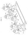
- the machining centre with one or more operating units and with part handling units of this invention preferably with two operating units, whose reference number in the assembly is 10 in figures figure 1 and 1A, includes a bearing frame 12, for instance with a regular parallelepiped or prismatic expansion, formed of a plurality of beams or side members connected to one another in a known manner.
- the bearing frame 12 acts as a support for two pairs of linear slides 28, 28' to which two operating units 18, 20, are connected, respectively, which, in association with carriages or skids 26,26', prove to be sliding on cross members 14, 16, which, in turn, are moved on the mentioned rails 28, 28' located on different levels or misaligned from one another.
- figure 1A depicts the machining centre 10 without the bearing frame 12 and provided with an adjoining magazine 22, per se already known, where the parts to be machined are stored and grouped.
- the linear slides 28, 28' are located orthogonal to one another; it is therefore to be understood that such slides can be oriented otherwise, forming whatever angle shot, or parallel but misaligned from one another.
- Each cross member 14, 16 is equipped with a carriage 26, 26' along which the units 18 and 20 can move orthogonally as to the linear development of the slides themselves.
- these very cross members 14 and 16 are coupled with traditional sliding rails 28 28', along one of the Cartesian axes, as specified hereinafter.
- the sliding of cross members 14 and 16 on slides 28 and 28' is controlled by means of known devices such as precision motors and reducers 29 and 29' which, through special pinions, act on racks 31 and 31', or by means of ball bearing screws.
- the movement of operating units 18 and 20 is likewise controlled by means of motors (not shown either), connected to further similar screws 33 and 33' through belts 35 and 35'.
- the machining centre 10 also includes one or more benches 32 held by frames 32' that support the parts 24 that are from time to time picked from the magazine 22 as indicated below.
- Each of the operating units 18, 20 is equipped at one end with a revolving head 34, which supports a traditional electric chuck 36, which, in turn, rotates in a known way on the front side of head 34 which it is connected to.
- Electric chucks 36 include opposed shafts that are combined in a known way with the tools 38 required to execute the various machining sessions over the parts 24.
- Under the bench/benches 32 or adjoining it a storing and clearing device fro machined parts is located, one of which is referenced with 24' in figure 1A, such as for instance a conveyor belt 40, suited to transfer the parts 24 that have already been machined.
- Electric chucks 36 can move along 5 axes, as schematised in figures 2 and 3 in a detailed view.
- the "X" axis corresponds to the travel of units 18, 20 along the rails 28, 28', the “Y” axis along cross members 14, 16,- and the “Z” axis along similar slides.
- Axes "A” and “C” correspond to the rotation of electric chucks 36 as to the heads 34, and to the rotation of the latter heads as to units 18, 20, respectively.
- the parts 24 can be simultaneously machined in whatever position; once located on benches 32, where they are stabilized with known means, they do not typically demand any further handling, that is they may be treated in whatever position or face owing to the location of the operating units 18 and 20 with the associated electric chucks 36 and tools 38.
- unit 14 located on top can easily access the machining to be executed on the upper, rear and side front faces of part 24; the lower horizontal unit 20, on the contrary, can easily access the upper, lower, rear and side faces.
- Figures 4 and 5 schematically depict the possible operating range of units 18, 20; figure 4 depicts the range of unit 18 or upper vertical unit, whereas figure 5 depicts that of unit 20 or lower horizontal unit.
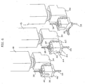
- the machining centre 10 of this invention includes handling or picking and placing means 24 for the parts to be machined, such means being basically integrated or coupled with at least one of electric mandrels 36, preferably with both electric chucks that have been respectively brought from each operating unit 18 and 20.
- These handling or picking and handling means 24 and 24' include, in accordance with the preferred embodiment shown in figures 6 and 7, a pneumatic cylinder 42 or equivalent part, whose rod 44 is moved towards the locators 46.
- Both the cylinder 42 and the locators 46 are mounted so as to be moved; therefore, during the machining, the locators 46 are supposed to be withdrawn inside special housings 46' and the cylinder 42 is lowered until it touches the electric mandrel surface 36. These movements are preferably controlled by means of pneumatic or hydraulic cylinders 45 and 47, and allow the dimensions that might reduce the electric chuck operativeness to be removed or reduced in a substantial way.
- the locators 46 and the cylinder 42 are only exposed when a part 24 needs to be picked from the magazine 22 to be placed on work benches 32, or to move, capsize or remove a machined part 24' from the work benches 32 and place it on the stacking and clearing means 40.
- Each part 24 is picked from the magazine 22 by inserting the locators 46, previously exposed through the action of cylinders 45, under the part itself, which is at the bottom of the stack, and hence actuating the cylinder 42 previously raised from the surface of the electric chuck 36 through the action of cylinder 47.
- the rod 44 at this very moment, locates part 24 by compressing it against the locators 46 and temporarily stabilizing it.
- the unit 18 or 20 that bears the electric chuck 36 that caught the part is then duly moved along one or more axes to take the part 24 onto one of the benches 32 and lay it there, provided that the stem 44 of cylinder 42 moves backwards before.
- both the locators 46 and the cylinder 42 are retracted and taken to their hidden position.
- the cylinder 42 and the related locators 36 are preferably fastened above or at one side of both electric chucks 36 taken by the operating units 18 and 20.
- the part is blocked on benches 32, which provide bearings 52 that can be revolved and tilted on the horizontal axis B.
- These benches are advantageously made by faceting the body of small-gauged cylinders which can thus be rotated in special locations.
- These cylinders provide for the part to be pinched on the front and rear sides, so that most of the surfaces to be machined remain free. Their stroke is suited to the gripping of variable-width parts.
- This invention may also include other replacement or additional systems of known type, which are such as to allow parts having extended or more or less bulky shapes to be lodged and blocked.
- the machining centre is equipped with automatic and fast loading/unloading means for parts having extended shapes.
- the benches will be equipped with traditional pneumatic clamping devices with pressing members that operate in a bottom-up or a top-down direction.
- each bench 32 actually includes a blocking device in position 54 which is released by the action of one of the two operating units 18 and 20.
- a special pin 56 is inserted into a special seat provided on the operating unit and the movement of the operating units along the longitudinal slides 28, 28' allows the bench-holding columns 50 to be positioned along special slides 58 in pre-arranged positions of the part machining programme to be executed.
- the driving pin 56 Upon release of the driving pin 56, the column 50 locks in place.
- Each operating unit can thus turn into a part handling robot as well as into an automatic machine setting system.
- the machining centre 10 of this invention allows for operating in whatever position over the whole surface exposed or on all faces of the parts 24, regardless of their section and does not normally demand intermediate handling of the parts, once these have been placed and secured to the bench 32.
- the machining centre of this invention actually allows the part to be translated or capsized while it is being machined.
- This machining centre also features a monolithic structure that properly supports the operating units, the loading/unloading systems and the part resting and clamping benches, with the achievement of rigidity and accuracy values that are typical of numerically-controlled systems.
- a special benefit is derived from the possibility of easily handling the parts 24 without resorting to cumbersome and expensive handling robots, as the means 42, 46 are provided directly on the operating units 18, 20 and, preferably, on the electric chucks 36, too.
- these handling means which can move along the 5 axes provided to move the operating units, will allow a part 24 to be capsized or relocated on the benches even during the work cycle, so as to promote the full machining of all the part faces. In fact, it may be necessary to work on the part resting or clamping areas on the benches and, in such a case, it is indispensable to move or capsize it.
Landscapes
- Engineering & Computer Science (AREA)
- Mechanical Engineering (AREA)
- Life Sciences & Earth Sciences (AREA)
- Wood Science & Technology (AREA)
- Forests & Forestry (AREA)
- Feeding Of Workpieces (AREA)
- Multi-Process Working Machines And Systems (AREA)
- Electrical Discharge Machining, Electrochemical Machining, And Combined Machining (AREA)
- Jigs For Machine Tools (AREA)
- Milling, Drilling, And Turning Of Wood (AREA)
- Manipulator (AREA)
- Machine Tool Units (AREA)
Applications Claiming Priority (1)
| Application Number | Priority Date | Filing Date | Title |
|---|---|---|---|
| IT000671A ITMI20050671A1 (it) | 2005-04-15 | 2005-04-15 | Centro di lavoro a una o piu'unita'operatrici con manipolatori dei pezzi |
Publications (2)
| Publication Number | Publication Date |
|---|---|
| EP1712337A1 true EP1712337A1 (de) | 2006-10-18 |
| EP1712337B1 EP1712337B1 (de) | 2008-02-20 |
Family
ID=36677223
Family Applications (1)
| Application Number | Title | Priority Date | Filing Date |
|---|---|---|---|
| EP06006074A Expired - Lifetime EP1712337B1 (de) | 2005-04-15 | 2006-03-24 | Bearbeitungszentrum mit zwei Arbeitseinheiten mit Mitteln zur Handhabung des Werkstücks |
Country Status (5)
| Country | Link |
|---|---|
| EP (1) | EP1712337B1 (de) |
| AT (1) | ATE386625T1 (de) |
| DE (1) | DE602006000545T2 (de) |
| ES (1) | ES2302270T3 (de) |
| IT (1) | ITMI20050671A1 (de) |
Cited By (24)
| Publication number | Priority date | Publication date | Assignee | Title |
|---|---|---|---|---|
| EP1923183A1 (de) | 2006-11-15 | 2008-05-21 | Essetre S.P.A. | Fräsmaschine zur Bearbeitung von Holzbalken |
| EP2017035A1 (de) * | 2007-07-17 | 2009-01-21 | B.G.M. S.r.l. | Hängevorrichtung zum Halten von Werkzeugen |
| DE202008012632U1 (de) * | 2008-09-23 | 2010-02-25 | Weeke Bohrsysteme Gmbh | Bearbeitungsmaschine für sechsseitige Bearbeitung |
| ITPD20080363A1 (it) * | 2008-12-04 | 2010-06-05 | Essetre Holding S R L | Centro di lavoro particolarmente del tipo per eseguire fresature o taglio di pannelli in legno |
| ITMO20100042A1 (it) * | 2010-02-25 | 2011-08-26 | Scm Group Spa | Gruppo operativo per un centro di lavoro |
| ITMI20110036A1 (it) * | 2011-01-18 | 2012-07-19 | Antonio Balestrini | Testa birotativa perfezionata, specie per centri di lavoro a quattro o piu' assi |
| EP2353820A3 (de) * | 2010-02-10 | 2013-11-13 | Hans Hundegger | Holzbearbeitungsanlage |
| ITMI20121751A1 (it) * | 2012-10-16 | 2014-04-17 | Pade S R L | Centro di lavoro per la lavorazione del legno |
| EP2862671A1 (de) * | 2013-10-15 | 2015-04-22 | BDM Germany GmbH | Vorrichtung zur Bearbeitung von stangenförmigen Profilrohlingen |
| DE102008029074B4 (de) * | 2007-06-12 | 2017-07-06 | Scm Group S.P.A. | Bearbeitungszentrum |
| DE102017121393A1 (de) | 2016-09-16 | 2018-03-22 | C.M.S. S.P.A. | Bearbeitungszentrum mit numerischer Steuerung |
| CN108214707A (zh) * | 2018-01-22 | 2018-06-29 | 湖南劳动人事职业学院 | 一种全自动木质佛珠铣形钻孔机 |
| DE102017120471A1 (de) * | 2017-09-06 | 2019-03-07 | Hans Hundegger | Plattenbearbeitungsanlage |
| IT201800001628A1 (it) * | 2018-01-22 | 2019-07-22 | Scm Group Spa | Macchina utensile e relativo metodo di funzionamento. |
| US10384491B2 (en) | 2015-12-10 | 2019-08-20 | Sumitomo Rubber Indusiries, Ltd. | Pneumatic tire |
| WO2019182046A1 (ja) * | 2018-03-22 | 2019-09-26 | 国立大学法人千葉大学 | 木材加工システム |
| WO2020239152A3 (de) * | 2019-05-27 | 2021-01-21 | Martin Zimmer | Werkstückbearbeitungsstation mit handhabungsgerätgeführter multibearbeitungseinheit |
| IT202000008404A1 (it) * | 2020-04-20 | 2021-10-20 | Cms Spa | Macchina bifronte di lavorazione industriale. |
| CN114535714A (zh) * | 2022-04-25 | 2022-05-27 | 深圳市国天电子股份有限公司 | 车载毫米雷达罩高精度加工设备及方法 |
| CN114670037A (zh) * | 2022-02-28 | 2022-06-28 | 金雷科技股份公司 | 一种风力发电主轴支撑装置 |
| CN117324966A (zh) * | 2023-12-01 | 2024-01-02 | 常州市蓝托金属制品有限公司 | 一种航空座椅侧扶手支架多孔加工设备及方法 |
| IT202300013047A1 (it) * | 2023-06-23 | 2024-12-23 | F O M Ind S R L | Macchina per il taglio e la lavorazione di profilati, in particolare di alluminio, leghe leggere, pvc o simili |
| IT202300023079A1 (it) * | 2023-11-02 | 2025-05-02 | Emmegi Spa | Apparato e metodo per lavorare barre profilate |
| EP4659921A1 (de) * | 2024-06-04 | 2025-12-10 | SCM Group S.p.A. | Maschine zur bearbeitung eines werkstücks |
Families Citing this family (6)
| Publication number | Priority date | Publication date | Assignee | Title |
|---|---|---|---|---|
| CH713011A2 (de) | 2016-10-06 | 2018-04-13 | Kruesi Maschb Ag | Holzbearbeitungsvorrichtung. |
| CN107322712A (zh) * | 2017-08-16 | 2017-11-07 | 广州市鸿申数控机械有限公司 | 一种用于五轴联动榫槽的加工中心 |
| RU183733U1 (ru) * | 2018-04-06 | 2018-10-02 | Чу-Нэн ЮЙ | Комбинированный токарно-фрезерный станок с чпу |
| CN110978155A (zh) * | 2019-12-24 | 2020-04-10 | 嘉兴智华家居有限公司 | 一种多功能实木加工装置 |
| IT202200017946A1 (it) * | 2022-09-01 | 2024-03-01 | elumatec AG | Testa operatrice e metodo per lavorare barre profilate. |
| DE102022122111A1 (de) * | 2022-09-01 | 2024-03-07 | Hans Hundegger Beteiligungs Gmbh & Co. Kg | Plattenbearbeitungsanlage |
Citations (4)
| Publication number | Priority date | Publication date | Assignee | Title |
|---|---|---|---|---|
| EP0608746A1 (de) * | 1993-01-19 | 1994-08-03 | BALJER & ZEMBROD GmbH & Co. | CNC-gesteuerte Holzbearbeitungsanlage, insbesondere für lange Werkstücke wie Balken |
| DE29603804U1 (de) * | 1996-03-01 | 1996-10-02 | Botje, Karin, 34477 Twistetal | Fräs- und Trennmaschine zur Holzbearbeitung |
| DE19518965A1 (de) * | 1995-05-23 | 1996-11-28 | Homag Maschinenbau Ag | Bearbeitungszentrum und Bearbeitungsverfahren für Holz- und Kunststoff-Werkstoffe |
| EP1250976A1 (de) * | 2001-04-20 | 2002-10-23 | Bacci Paolino Di Bacci Di Agostino | Werkzeugmaschinen zum bearbeiten von länglichen Werkstücken |
-
2005
- 2005-04-15 IT IT000671A patent/ITMI20050671A1/it unknown
-
2006
- 2006-03-24 EP EP06006074A patent/EP1712337B1/de not_active Expired - Lifetime
- 2006-03-24 ES ES06006074T patent/ES2302270T3/es not_active Expired - Lifetime
- 2006-03-24 AT AT06006074T patent/ATE386625T1/de not_active IP Right Cessation
- 2006-03-24 DE DE602006000545T patent/DE602006000545T2/de not_active Expired - Lifetime
Patent Citations (4)
| Publication number | Priority date | Publication date | Assignee | Title |
|---|---|---|---|---|
| EP0608746A1 (de) * | 1993-01-19 | 1994-08-03 | BALJER & ZEMBROD GmbH & Co. | CNC-gesteuerte Holzbearbeitungsanlage, insbesondere für lange Werkstücke wie Balken |
| DE19518965A1 (de) * | 1995-05-23 | 1996-11-28 | Homag Maschinenbau Ag | Bearbeitungszentrum und Bearbeitungsverfahren für Holz- und Kunststoff-Werkstoffe |
| DE29603804U1 (de) * | 1996-03-01 | 1996-10-02 | Botje, Karin, 34477 Twistetal | Fräs- und Trennmaschine zur Holzbearbeitung |
| EP1250976A1 (de) * | 2001-04-20 | 2002-10-23 | Bacci Paolino Di Bacci Di Agostino | Werkzeugmaschinen zum bearbeiten von länglichen Werkstücken |
Cited By (36)
| Publication number | Priority date | Publication date | Assignee | Title |
|---|---|---|---|---|
| EP1923183A1 (de) | 2006-11-15 | 2008-05-21 | Essetre S.P.A. | Fräsmaschine zur Bearbeitung von Holzbalken |
| DE102008029074B4 (de) * | 2007-06-12 | 2017-07-06 | Scm Group S.P.A. | Bearbeitungszentrum |
| EP2017035A1 (de) * | 2007-07-17 | 2009-01-21 | B.G.M. S.r.l. | Hängevorrichtung zum Halten von Werkzeugen |
| DE202008012632U1 (de) * | 2008-09-23 | 2010-02-25 | Weeke Bohrsysteme Gmbh | Bearbeitungsmaschine für sechsseitige Bearbeitung |
| WO2010034530A1 (de) * | 2008-09-23 | 2010-04-01 | Weeke Bohrsysteme Gmbh | Bearbeitungsmaschine für sechsseitige bearbeitung |
| ITPD20080363A1 (it) * | 2008-12-04 | 2010-06-05 | Essetre Holding S R L | Centro di lavoro particolarmente del tipo per eseguire fresature o taglio di pannelli in legno |
| EP2353820A3 (de) * | 2010-02-10 | 2013-11-13 | Hans Hundegger | Holzbearbeitungsanlage |
| EP2894018A1 (de) * | 2010-02-10 | 2015-07-15 | Hans Hundegger | Holzbearbeitungsanlage |
| EP2361738A1 (de) * | 2010-02-25 | 2011-08-31 | SCM Group S.p.A. | Arbeitskopf für ein Bearbeitungszentrum |
| ITMO20100042A1 (it) * | 2010-02-25 | 2011-08-26 | Scm Group Spa | Gruppo operativo per un centro di lavoro |
| ITMI20110036A1 (it) * | 2011-01-18 | 2012-07-19 | Antonio Balestrini | Testa birotativa perfezionata, specie per centri di lavoro a quattro o piu' assi |
| ITMI20121751A1 (it) * | 2012-10-16 | 2014-04-17 | Pade S R L | Centro di lavoro per la lavorazione del legno |
| EP2862671A1 (de) * | 2013-10-15 | 2015-04-22 | BDM Germany GmbH | Vorrichtung zur Bearbeitung von stangenförmigen Profilrohlingen |
| US10384491B2 (en) | 2015-12-10 | 2019-08-20 | Sumitomo Rubber Indusiries, Ltd. | Pneumatic tire |
| DE102017121393A1 (de) | 2016-09-16 | 2018-03-22 | C.M.S. S.P.A. | Bearbeitungszentrum mit numerischer Steuerung |
| DE102017120471A1 (de) * | 2017-09-06 | 2019-03-07 | Hans Hundegger | Plattenbearbeitungsanlage |
| CN108214707A (zh) * | 2018-01-22 | 2018-06-29 | 湖南劳动人事职业学院 | 一种全自动木质佛珠铣形钻孔机 |
| IT201800001628A1 (it) * | 2018-01-22 | 2019-07-22 | Scm Group Spa | Macchina utensile e relativo metodo di funzionamento. |
| EP3513907A1 (de) * | 2018-01-22 | 2019-07-24 | SCM Group S.p.A. | Werkzeugmaschine und verfahren zum betreiben der werkzeugmaschine |
| WO2019182046A1 (ja) * | 2018-03-22 | 2019-09-26 | 国立大学法人千葉大学 | 木材加工システム |
| JP2019166657A (ja) * | 2018-03-22 | 2019-10-03 | 国立大学法人千葉大学 | 木材加工システム |
| US11648705B2 (en) | 2018-03-22 | 2023-05-16 | National University Corporation Chiba University | Wood processing system |
| WO2020239152A3 (de) * | 2019-05-27 | 2021-01-21 | Martin Zimmer | Werkstückbearbeitungsstation mit handhabungsgerätgeführter multibearbeitungseinheit |
| CN114450125A (zh) * | 2019-05-27 | 2022-05-06 | 马丁·齐默尔 | 具有操作设备引导的多重加工单元的工件加工站 |
| EP3900901A1 (de) * | 2020-04-20 | 2021-10-27 | C.M.S. S.p.A. | Doppelseitige maschine zur industriellen verarbeitung |
| CN113524358A (zh) * | 2020-04-20 | 2021-10-22 | C.M.S.股份公司 | 用于工业加工的双面机器 |
| IT202000008404A1 (it) * | 2020-04-20 | 2021-10-20 | Cms Spa | Macchina bifronte di lavorazione industriale. |
| CN114670037A (zh) * | 2022-02-28 | 2022-06-28 | 金雷科技股份公司 | 一种风力发电主轴支撑装置 |
| CN114535714A (zh) * | 2022-04-25 | 2022-05-27 | 深圳市国天电子股份有限公司 | 车载毫米雷达罩高精度加工设备及方法 |
| IT202300013047A1 (it) * | 2023-06-23 | 2024-12-23 | F O M Ind S R L | Macchina per il taglio e la lavorazione di profilati, in particolare di alluminio, leghe leggere, pvc o simili |
| EP4480632A1 (de) * | 2023-06-23 | 2024-12-25 | F.O.M. Industrie S.r.l. | Maschine zum schneiden und bearbeiten von profilstäben, insbesondere aus aluminium, leichtmetalllegierungen, pvc oder dergleichen |
| IT202300023079A1 (it) * | 2023-11-02 | 2025-05-02 | Emmegi Spa | Apparato e metodo per lavorare barre profilate |
| EP4549084A1 (de) * | 2023-11-02 | 2025-05-07 | Emmegi S.P.A. | Vorrichtung und verfahren zur bearbeitung von profilen |
| CN117324966A (zh) * | 2023-12-01 | 2024-01-02 | 常州市蓝托金属制品有限公司 | 一种航空座椅侧扶手支架多孔加工设备及方法 |
| CN117324966B (zh) * | 2023-12-01 | 2024-02-02 | 常州市蓝托金属制品有限公司 | 一种航空座椅侧扶手支架多孔加工设备及方法 |
| EP4659921A1 (de) * | 2024-06-04 | 2025-12-10 | SCM Group S.p.A. | Maschine zur bearbeitung eines werkstücks |
Also Published As
| Publication number | Publication date |
|---|---|
| ES2302270T3 (es) | 2008-07-01 |
| ATE386625T1 (de) | 2008-03-15 |
| ITMI20050671A1 (it) | 2006-10-16 |
| DE602006000545D1 (de) | 2008-04-03 |
| DE602006000545T2 (de) | 2009-02-19 |
| EP1712337B1 (de) | 2008-02-20 |
Similar Documents
| Publication | Publication Date | Title |
|---|---|---|
| EP1712337A1 (de) | Bearbeitungszentrum mit zwei Arbeitseinheiten mit Mitteln zur Handhabung des Werkstücks | |
| EP2067586A2 (de) | Holzbearbeitungsmaschine | |
| RU2389599C2 (ru) | Манипуляционная система | |
| EP2035199B1 (de) | Werkzeugmaschine oder bearbeitungszentrum mit numerisch gesteuerter doppelter einstellung der klemmelemente | |
| US20030099522A1 (en) | Device for mechanically rough machining and/or finish machining cast parts | |
| JPH0716722B2 (ja) | 交換可能な押抜き工具とワーク送り装置を有する押抜き機 | |
| EP3050657B1 (de) | Automatisierte vorrichtung zur verarbeitung von tafeln aus holzähnlichen werkstoffen | |
| CN102015205B (zh) | 托板装载器和操纵器 | |
| EP0364858B1 (de) | Paletten-Wechselvorrichtung | |
| US20160082559A1 (en) | Machine tool | |
| CN113828829B (zh) | 轴线加工一体机 | |
| US20090053000A1 (en) | Compact High Precision Multiple Spindle Computer Controlled Machine Tool | |
| CN110977583A (zh) | 一种轴类环状定位槽自动加工装置 | |
| US5465471A (en) | Apparatus for machining bars | |
| JP6618544B2 (ja) | 多機能ワーク置き台モジュール | |
| KR20130029028A (ko) | 공작기계 및 워크의 공급·배출방법 | |
| WO2008004263A2 (en) | Machining centre with positioning system of the workpiece clamping members | |
| EP1247611B1 (de) | Mehrachsiges Bearbeitungszentrum für mehrfache Bearbeitung, insbesondere für Holzbearbeitung | |
| EP4277773B1 (de) | Vorrichtung und verfahren zum bewegen von werkstückpaaren mit einer rauhen und einer entgegengerichteten fläche | |
| CN110340649B (zh) | 一种多角度自动锁螺丝机 | |
| US20090090155A1 (en) | Sheet-Metal Working Machine and Method for Machining Sheets | |
| US20210178544A1 (en) | Cnc machining centre | |
| EP1719574A1 (de) | Arbeitsanlage mit mehreren numerisch gesteuerten Achsen zum Bearbeitung von länglichen Werkstücken, insbesondere aus Holz | |
| CN116572059A (zh) | 一种立式加工中心的自动换料装置 | |
| JPH0197542A (ja) | パレット交換方法 |
Legal Events
| Date | Code | Title | Description |
|---|---|---|---|
| PUAI | Public reference made under article 153(3) epc to a published international application that has entered the european phase |
Free format text: ORIGINAL CODE: 0009012 |
|
| AK | Designated contracting states |
Kind code of ref document: A1 Designated state(s): AT BE BG CH CY CZ DE DK EE ES FI FR GB GR HU IE IS IT LI LT LU LV MC NL PL PT RO SE SI SK TR |
|
| AX | Request for extension of the european patent |
Extension state: AL BA HR MK YU |
|
| 17P | Request for examination filed |
Effective date: 20070410 |
|
| 17Q | First examination report despatched |
Effective date: 20070511 |
|
| AKX | Designation fees paid |
Designated state(s): AT BE BG CH CY CZ DE DK EE ES FI FR GB GR HU IE IS IT LI LT LU LV MC NL PL PT RO SE SI SK TR |
|
| GRAP | Despatch of communication of intention to grant a patent |
Free format text: ORIGINAL CODE: EPIDOSNIGR1 |
|
| GRAS | Grant fee paid |
Free format text: ORIGINAL CODE: EPIDOSNIGR3 |
|
| GRAA | (expected) grant |
Free format text: ORIGINAL CODE: 0009210 |
|
| AK | Designated contracting states |
Kind code of ref document: B1 Designated state(s): AT BE BG CH CY CZ DE DK EE ES FI FR GB GR HU IE IS IT LI LT LU LV MC NL PL PT RO SE SI SK TR |
|
| REG | Reference to a national code |
Ref country code: GB Ref legal event code: FG4D |
|
| REG | Reference to a national code |
Ref country code: CH Ref legal event code: EP |
|
| REG | Reference to a national code |
Ref country code: IE Ref legal event code: FG4D |
|
| REF | Corresponds to: |
Ref document number: 602006000545 Country of ref document: DE Date of ref document: 20080403 Kind code of ref document: P |
|
| REG | Reference to a national code |
Ref country code: ES Ref legal event code: FG2A Ref document number: 2302270 Country of ref document: ES Kind code of ref document: T3 |
|
| PG25 | Lapsed in a contracting state [announced via postgrant information from national office to epo] |
Ref country code: IS Free format text: LAPSE BECAUSE OF FAILURE TO SUBMIT A TRANSLATION OF THE DESCRIPTION OR TO PAY THE FEE WITHIN THE PRESCRIBED TIME-LIMIT Effective date: 20080620 Ref country code: FI Free format text: LAPSE BECAUSE OF FAILURE TO SUBMIT A TRANSLATION OF THE DESCRIPTION OR TO PAY THE FEE WITHIN THE PRESCRIBED TIME-LIMIT Effective date: 20080220 |
|
| NLV1 | Nl: lapsed or annulled due to failure to fulfill the requirements of art. 29p and 29m of the patents act | ||
| PG25 | Lapsed in a contracting state [announced via postgrant information from national office to epo] |
Ref country code: AT Free format text: LAPSE BECAUSE OF FAILURE TO SUBMIT A TRANSLATION OF THE DESCRIPTION OR TO PAY THE FEE WITHIN THE PRESCRIBED TIME-LIMIT Effective date: 20080220 |
|
| PG25 | Lapsed in a contracting state [announced via postgrant information from national office to epo] |
Ref country code: LV Free format text: LAPSE BECAUSE OF FAILURE TO SUBMIT A TRANSLATION OF THE DESCRIPTION OR TO PAY THE FEE WITHIN THE PRESCRIBED TIME-LIMIT Effective date: 20080220 Ref country code: PL Free format text: LAPSE BECAUSE OF FAILURE TO SUBMIT A TRANSLATION OF THE DESCRIPTION OR TO PAY THE FEE WITHIN THE PRESCRIBED TIME-LIMIT Effective date: 20080220 Ref country code: BE Free format text: LAPSE BECAUSE OF FAILURE TO SUBMIT A TRANSLATION OF THE DESCRIPTION OR TO PAY THE FEE WITHIN THE PRESCRIBED TIME-LIMIT Effective date: 20080220 Ref country code: SI Free format text: LAPSE BECAUSE OF FAILURE TO SUBMIT A TRANSLATION OF THE DESCRIPTION OR TO PAY THE FEE WITHIN THE PRESCRIBED TIME-LIMIT Effective date: 20080220 |
|
| PG25 | Lapsed in a contracting state [announced via postgrant information from national office to epo] |
Ref country code: PT Free format text: LAPSE BECAUSE OF FAILURE TO SUBMIT A TRANSLATION OF THE DESCRIPTION OR TO PAY THE FEE WITHIN THE PRESCRIBED TIME-LIMIT Effective date: 20080721 Ref country code: CZ Free format text: LAPSE BECAUSE OF FAILURE TO SUBMIT A TRANSLATION OF THE DESCRIPTION OR TO PAY THE FEE WITHIN THE PRESCRIBED TIME-LIMIT Effective date: 20080220 Ref country code: SK Free format text: LAPSE BECAUSE OF FAILURE TO SUBMIT A TRANSLATION OF THE DESCRIPTION OR TO PAY THE FEE WITHIN THE PRESCRIBED TIME-LIMIT Effective date: 20080220 Ref country code: MC Free format text: LAPSE BECAUSE OF NON-PAYMENT OF DUE FEES Effective date: 20080331 Ref country code: DK Free format text: LAPSE BECAUSE OF FAILURE TO SUBMIT A TRANSLATION OF THE DESCRIPTION OR TO PAY THE FEE WITHIN THE PRESCRIBED TIME-LIMIT Effective date: 20080220 Ref country code: NL Free format text: LAPSE BECAUSE OF FAILURE TO SUBMIT A TRANSLATION OF THE DESCRIPTION OR TO PAY THE FEE WITHIN THE PRESCRIBED TIME-LIMIT Effective date: 20080220 Ref country code: SE Free format text: LAPSE BECAUSE OF FAILURE TO SUBMIT A TRANSLATION OF THE DESCRIPTION OR TO PAY THE FEE WITHIN THE PRESCRIBED TIME-LIMIT Effective date: 20080520 |
|
| PG25 | Lapsed in a contracting state [announced via postgrant information from national office to epo] |
Ref country code: RO Free format text: LAPSE BECAUSE OF FAILURE TO SUBMIT A TRANSLATION OF THE DESCRIPTION OR TO PAY THE FEE WITHIN THE PRESCRIBED TIME-LIMIT Effective date: 20080220 |
|
| EN | Fr: translation not filed | ||
| PLBE | No opposition filed within time limit |
Free format text: ORIGINAL CODE: 0009261 |
|
| STAA | Information on the status of an ep patent application or granted ep patent |
Free format text: STATUS: NO OPPOSITION FILED WITHIN TIME LIMIT |
|
| 26N | No opposition filed |
Effective date: 20081121 |
|
| PG25 | Lapsed in a contracting state [announced via postgrant information from national office to epo] |
Ref country code: LT Free format text: LAPSE BECAUSE OF FAILURE TO SUBMIT A TRANSLATION OF THE DESCRIPTION OR TO PAY THE FEE WITHIN THE PRESCRIBED TIME-LIMIT Effective date: 20080220 Ref country code: EE Free format text: LAPSE BECAUSE OF FAILURE TO SUBMIT A TRANSLATION OF THE DESCRIPTION OR TO PAY THE FEE WITHIN THE PRESCRIBED TIME-LIMIT Effective date: 20080220 Ref country code: IE Free format text: LAPSE BECAUSE OF NON-PAYMENT OF DUE FEES Effective date: 20080324 |
|
| PG25 | Lapsed in a contracting state [announced via postgrant information from national office to epo] |
Ref country code: FR Free format text: LAPSE BECAUSE OF FAILURE TO SUBMIT A TRANSLATION OF THE DESCRIPTION OR TO PAY THE FEE WITHIN THE PRESCRIBED TIME-LIMIT Effective date: 20081212 Ref country code: BG Free format text: LAPSE BECAUSE OF FAILURE TO SUBMIT A TRANSLATION OF THE DESCRIPTION OR TO PAY THE FEE WITHIN THE PRESCRIBED TIME-LIMIT Effective date: 20080520 |
|
| PG25 | Lapsed in a contracting state [announced via postgrant information from national office to epo] |
Ref country code: CY Free format text: LAPSE BECAUSE OF FAILURE TO SUBMIT A TRANSLATION OF THE DESCRIPTION OR TO PAY THE FEE WITHIN THE PRESCRIBED TIME-LIMIT Effective date: 20080220 |
|
| PG25 | Lapsed in a contracting state [announced via postgrant information from national office to epo] |
Ref country code: IT Free format text: LAPSE BECAUSE OF FAILURE TO SUBMIT A TRANSLATION OF THE DESCRIPTION OR TO PAY THE FEE WITHIN THE PRESCRIBED TIME-LIMIT Effective date: 20080220 |
|
| PG25 | Lapsed in a contracting state [announced via postgrant information from national office to epo] |
Ref country code: LU Free format text: LAPSE BECAUSE OF NON-PAYMENT OF DUE FEES Effective date: 20080324 Ref country code: HU Free format text: LAPSE BECAUSE OF FAILURE TO SUBMIT A TRANSLATION OF THE DESCRIPTION OR TO PAY THE FEE WITHIN THE PRESCRIBED TIME-LIMIT Effective date: 20080821 |
|
| PG25 | Lapsed in a contracting state [announced via postgrant information from national office to epo] |
Ref country code: TR Free format text: LAPSE BECAUSE OF FAILURE TO SUBMIT A TRANSLATION OF THE DESCRIPTION OR TO PAY THE FEE WITHIN THE PRESCRIBED TIME-LIMIT Effective date: 20080220 |
|
| PG25 | Lapsed in a contracting state [announced via postgrant information from national office to epo] |
Ref country code: GR Free format text: LAPSE BECAUSE OF FAILURE TO SUBMIT A TRANSLATION OF THE DESCRIPTION OR TO PAY THE FEE WITHIN THE PRESCRIBED TIME-LIMIT Effective date: 20080521 |
|
| REG | Reference to a national code |
Ref country code: CH Ref legal event code: PL |
|
| GBPC | Gb: european patent ceased through non-payment of renewal fee |
Effective date: 20100324 |
|
| PG25 | Lapsed in a contracting state [announced via postgrant information from national office to epo] |
Ref country code: LI Free format text: LAPSE BECAUSE OF NON-PAYMENT OF DUE FEES Effective date: 20100331 Ref country code: CH Free format text: LAPSE BECAUSE OF NON-PAYMENT OF DUE FEES Effective date: 20100331 |
|
| PG25 | Lapsed in a contracting state [announced via postgrant information from national office to epo] |
Ref country code: GB Free format text: LAPSE BECAUSE OF NON-PAYMENT OF DUE FEES Effective date: 20100324 |
|
| REG | Reference to a national code |
Ref country code: DE Ref legal event code: R082 Ref document number: 602006000545 Country of ref document: DE Representative=s name: KLINGSEISEN & PARTNER, DE Ref country code: DE Ref legal event code: R081 Ref document number: 602006000545 Country of ref document: DE Owner name: C.M.S. S.P.A., IT Free format text: FORMER OWNER: BALESTRINI RENZO S.P.A., SEVESO, MILANO/MAILAND, IT Ref country code: DE Ref legal event code: R081 Ref document number: 602006000545 Country of ref document: DE Owner name: C.M.S. S.P.A., ZOGNO, IT Free format text: FORMER OWNER: BALESTRINI RENZO S.P.A., SEVESO, MILANO/MAILAND, IT Ref country code: DE Ref legal event code: R082 Ref document number: 602006000545 Country of ref document: DE Representative=s name: KLINGSEISEN, RINGS & PARTNER PATENTANWAELTE, DE |
|
| REG | Reference to a national code |
Ref country code: ES Ref legal event code: PC2A Owner name: C.M.S. COSTRUZIONI MACCHINE SPECIALI S.P.A. Effective date: 20151211 |
|
| REG | Reference to a national code |
Ref country code: DE Ref legal event code: R082 Ref document number: 602006000545 Country of ref document: DE Representative=s name: KLINGSEISEN, RINGS & PARTNER PATENTANWAELTE, DE Ref country code: DE Ref legal event code: R081 Ref document number: 602006000545 Country of ref document: DE Owner name: C.M.S. S.P.A., ZOGNO, IT Free format text: FORMER OWNER: C.M.S. S.P.A., SEVESO, IT |
|
| PGFP | Annual fee paid to national office [announced via postgrant information from national office to epo] |
Ref country code: ES Payment date: 20170328 Year of fee payment: 12 |
|
| REG | Reference to a national code |
Ref country code: ES Ref legal event code: FD2A Effective date: 20190911 |
|
| PG25 | Lapsed in a contracting state [announced via postgrant information from national office to epo] |
Ref country code: ES Free format text: LAPSE BECAUSE OF NON-PAYMENT OF DUE FEES Effective date: 20180325 |
|
| P01 | Opt-out of the competence of the unified patent court (upc) registered |
Effective date: 20230519 |
|
| PGFP | Annual fee paid to national office [announced via postgrant information from national office to epo] |
Ref country code: DE Payment date: 20250319 Year of fee payment: 20 |
|
| REG | Reference to a national code |
Ref country code: DE Ref legal event code: R071 Ref document number: 602006000545 Country of ref document: DE |