EP1716996A1 - Maschine zum Herstellen von Flanschen für Trommeln für elektrische Kabel durch Nageln von Holzteilen - Google Patents
Maschine zum Herstellen von Flanschen für Trommeln für elektrische Kabel durch Nageln von Holzteilen Download PDFInfo
- Publication number
- EP1716996A1 EP1716996A1 EP06006704A EP06006704A EP1716996A1 EP 1716996 A1 EP1716996 A1 EP 1716996A1 EP 06006704 A EP06006704 A EP 06006704A EP 06006704 A EP06006704 A EP 06006704A EP 1716996 A1 EP1716996 A1 EP 1716996A1
- Authority
- EP
- European Patent Office
- Prior art keywords
- nailing
- worktable
- pieces
- wood
- flange
- Prior art date
- Legal status (The legal status is an assumption and is not a legal conclusion. Google has not performed a legal analysis and makes no representation as to the accuracy of the status listed.)
- Granted
Links
- 239000002023 wood Substances 0.000 title claims abstract description 42
- 238000004519 manufacturing process Methods 0.000 title claims abstract description 8
- 238000005056 compaction Methods 0.000 claims abstract description 27
- 230000000670 limiting effect Effects 0.000 description 3
- 230000008021 deposition Effects 0.000 description 1
- 239000000463 material Substances 0.000 description 1
- 238000000034 method Methods 0.000 description 1
- 238000012986 modification Methods 0.000 description 1
- 230000004048 modification Effects 0.000 description 1
Images


Classifications
-
- B—PERFORMING OPERATIONS; TRANSPORTING
- B27—WORKING OR PRESERVING WOOD OR SIMILAR MATERIAL; NAILING OR STAPLING MACHINES IN GENERAL
- B27M—WORKING OF WOOD NOT PROVIDED FOR IN SUBCLASSES B27B - B27L; MANUFACTURE OF SPECIFIC WOODEN ARTICLES
- B27M3/00—Manufacture or reconditioning of specific semi-finished or finished articles
- B27M3/0013—Manufacture or reconditioning of specific semi-finished or finished articles of composite or compound articles
- B27M3/0073—Manufacture or reconditioning of specific semi-finished or finished articles of composite or compound articles characterised by nailing, stapling or screwing connections
-
- B—PERFORMING OPERATIONS; TRANSPORTING
- B65—CONVEYING; PACKING; STORING; HANDLING THIN OR FILAMENTARY MATERIAL
- B65H—HANDLING THIN OR FILAMENTARY MATERIAL, e.g. SHEETS, WEBS, CABLES
- B65H75/00—Storing webs, tapes, or filamentary material, e.g. on reels
- B65H75/50—Methods of making reels, bobbins, cop tubes, or the like by working an unspecified material, or several materials
Definitions
- the present invention relates to a machine for manufacturing flanges of electrical cable reels by nailing pieces of wood.
- electrical cable reels are generally constituted by a substantially cylindrical wooden core which has, at each end, a flange usually manufactured by superimposing and nailing two layers of pieces of wood so that the pieces of one layer lie substantially at right angles to the pieces of the other layer.
- Nailing for assembling the pieces of wood which compose reel flanges is performed by using nailing machines, generally constituted by a main supporting structure, which has a substantially horizontal worktable on which the two layers of wooden pieces, which compose the flange and are designed to be nailed, are deposited.
- Such machines are provided with compaction means and rotation means, which can be operated in order to keep the wooden pieces together during nailing and in order to cause their intermittent rotation about a vertical axis, which coincides with the axis of the flange, between the various nailing operations for assembly that are to be performed.
- the main supporting structure supports a first substantially horizontal bar, which supports the nailing plungers or hammers, which protrude downwardly from the first bar toward the worktable.
- a second bar is interposed between the first bar and the worktable, is substantially parallel to the first bar, and supports one or more parallel rows of nailing clamps.
- Each nailing clamp is crossed by a substantially vertical nailing channel, which is open at the top and at the bottom and is connected to a lateral feed duct, through which a nail is introduced in the nailing channel in each instance.
- the nailing clamps are provided so that the last portion of the nailing channel, which lies closest to the underlying worktable, can widen in order to allow the passage of the head of the nail during the nailing operation.
- a nailing plunger is provided, which is supported by the overlying first bar, and the first bar can move with respect to the second bar along a vertical direction in order to cause the advancement, during its motion toward the worktable, of the nailing plungers in the corresponding nailing channel of the nailing clamps and produce the expulsion of the nail, which is located in said channel, toward the worktable and in order to move the nailing plungers, during its motion away from the worktable, above the outlet of the feed duct in the corresponding nailing channel in order to allow the descent, into the nailing channel, of a new nail to be used in the subsequent nailing operation.
- the second bar also can move vertically in order to place, by way of its descent toward the worktable, the nailing clamps in contact, by means of their lower end in which the outlet of the nailing channel is provided, with the wooden pieces to be nailed or in order to disengage, with its upward motion, the nailing clamps from the pieces, which during the disengagement from the clamps are turned about a vertical axis, which coincides with the axis of the flange, in order to prepare them for the subsequent nailing operation.
- the compaction means are constituted simply by presses or clamps which, after being filled with the wooden pieces which constitute the flange, are closed manually and turned about the flange axis, again manually, in order to bring the flange to the various nailing positions.
- the compaction means comprise a plurality of arms which protrude from a central support, which is arranged above the worktable and is axially aligned with the axis of the flange about which such flange must be turned in order to be placed in the various nailing positions.
- Such arms are provided, proximate to their end which lies opposite the central support, with grip elements which are actuated pneumatically and can engage the edges of the flange in order to clamp the pieces of wood together, so as to reduce as much as possible the play among the various pieces.
- the rotation of the wooden pieces about the axis of the flange in order to place the flange in the various nailing positions is performed by way of the rotation means, constituted by a rotating element which is arranged on the worktable and can engage a central region of the lower face of the flange.
- the compaction means can interfere with the nailing clamps, limiting the possibility of rotation of the flange if the grip elements are kept engaged with the pieces of wood and therefore rotate with them.
- the grip elements are kept engaged with the wooden pieces of the flange only through a limited arc of rotation.
- the dimensions of the arms that support the grip elements, in known types of nailing machines, and the position of the nailing clamps are studied so as to allow to keep the grip elements engaged with the flange in performing a number of nailing operations which is limited but is such as to keep the pieces of wood that compose the flange correctly joined.
- the grip elements are disengaged from the flange so that the compaction means are no longer entrained by the rotation imparted to the flange, which continues to be turned about its own axis until the nailing operation is completed.
- the aim of the present invention is to solve the problem described above by providing a machine for manufacturing flanges of electrical cable reels by nailing pieces of wood, in which the presence of the compaction means does not limit the possibility of rotation of the flange about its own axis during nailing.
- an object of the invention is to provide a machine in which the compaction means can be kept engaged with the flange through an arc of rotation which is greater than the arc allowed by conventional machines or even through the entire rotation of the flange required to complete the nailing operation.
- Another object of the invention is to provide a machine in which it is possible to increase freely the number of nailing clamps in order to increase the productivity of the machine.
- Another object of the invention is to provide a machine which offers the greatest assurances of reliability and safety in use.
- a machine for manufacturing flanges of electrical cable reels by nailing pieces of wood comprising:
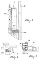
- the machine according to the invention comprises a main supporting structure 2, which supports a substantially horizontal worktable 3, on which the pieces of wood 4 are designed to be arranged, in a per se known manner, i.e., in two superimposed horizontal layers in which the pieces 4 of one layer are oriented at right angles to the pieces of the other layer, which must be nailed in order to obtain the flange 40 to be manufactured.
- the main supporting structure 2 supports at least one substantially horizontal bar 5b, which supports nailing clamps 6, which face the worktable 3 and can be actuated in a per se known manner in order to nail the pieces 4 arranged on the worktable 3.
- the main supporting structure 2 supports two bars: of which, a first substantially horizontal bar 5a, which supports the nailing plungers or hammers 7, which protrude downwardly from the first bar 5a toward the worktable 3.
- a second bar 5b is interposed between the first bar 5a and the worktable 3 and is substantially parallel to the first bar 5a and supports one or more parallel rows of nailing clamps 6.
- Each nailing clamp 6 is crossed by a substantially vertical nailing channel, which is open at the top and at the bottom and is connected to a lateral feed duct, through which a nail is introduced in the nailing channel in each instance.
- the nailing clamps 6 are provided so that the last portion of the nailing channel, which lies closest to the underlying worktable 3, can widen in order to allow the head of the nail to pass during the nailing operation.
- a nailing plunger 7 is provided, which is supported by the overlying first bar 5a, and the first bar 5a can move with respect to the second bar 5b along a vertical direction in order to cause the advancement, during its motion toward the worktable 3, of the nailing plungers 7 in the corresponding nailing channel of the nailing clamps 6 and produce the expulsion of the nail, which is located in said channel, toward the worktable 3 and in order to move the nailing plungers 7, during its motion away from the worktable 3, above the outlet of the feed duct in the corresponding nailing channel in order to allow the descent into the nailing channel of a new nail to be used in the subsequent nailing operation.
- the second bar 5b also can move vertically in order to arrange, with its descent toward the worktable 3, the nailing clamps 6 so that they make contact by means of their lower end, in which the outlet of the nailing channel is formed, with the pieces 4 to be nailed or so as to disengage, with its upward motion, the nailing clamps 6 from the pieces 4.
- the actuation of the first bar 5a and of the second bar 5b in order to nail the pieces of wood 4 deposited on the worktable 3 can be performed in a conventional manner or as disclosed in Italian Patent Application MI2004A-002392 by the same Applicant.
- the machine comprises compaction means 8, which can engage the pieces of wood 4 deposited on the worktable 3, and means 9 for turning such pieces of wood 4 about an axis 10 which is perpendicular to the worktable 3 and coincides with the axis of the flange 40 to be manufactured.
- the compaction means 8 are arranged and supported externally with respect to the region that lies above the worktable 3, which is occupied by the pieces of wood 4 of the flange 40 to be produced and by the nailing clamps 6. In this manner, the compaction means 8 cannot interfere in any way with the nailing clamps 6 during the rotation of the pieces of wood 4 performed by the rotation means 9, and the number of nailing clamps 6 can be increased with no problem so as to achieve, for the machine according to the invention, a productivity which is higher than that achievable with known types of machines.
- the compaction means 8 comprise at least one pair of pressers 11a, 11b, 12a, 12b, which are opposite one another and can move on command toward or away from each other so as to engage or disengage respective diametrically mutually opposite regions of the flange 40 being nailed and composed of the pieces of wood 4.
- the compaction means 8 comprise two pairs of pressers 11 a, 11b, 12a, 12b which are opposite one another and are arranged so as to engage two pairs of mutually diametrically opposite regions of the flange 40, which are mutually offset substantially through 90° about the axis 10 of the flange 40.
- the pressers 11a, 11b, 12a, 12b are each mounted on a supporting arm 13a, 13b, 14a, 14b, connected to a center bearing 15, which is arranged on a substantially horizontal plane above the worktable 3.
- the center bearing 15 is coaxial to the flange 40 being nailed and lies externally around the region of the worktable 3 which is designed to support the pieces of wood 4 of the flange being nailed.
- the diameter of the center bearing 15 is greater than the diameter of the biggest flange 40 that can be manufactured with the machine according to the invention.
- Each supporting arm 13a, 13b, 14a, 14b is arranged along a chord of the center bearing 15, and the supporting arms, on which pressers 11 a, 11b, 12a, 12b are arranged in mutually opposite positions, are substantially parallel to each other.
- Each supporting arm 13a, 13b, 14a, 14b has a variable length and its ends are connected to the center bearing 15 in connecting regions which can be changed in order to vary the distance of the pressers from the axis 10 of the center bearing 15 depending on the dimensions of the flange 40 being nailed.
- connection regions are formed by curved slots 16, 17, which are formed in the center bearing 15 and are coaxial to said center bearing 15.
- the ends of the supporting arms 13a, 13b, 14a, 14b are bolted in said slots 16, 17, in regions which can change according to the requirements.
- each supporting arm 13a, 13b, 14a, 14b in order to adapt it to the length of the chord of the center bearing 15 along which the supporting arm is arranged depending on the dimensions of the flange 40 being nailed, is achieved by providing each supporting arm 13a, 13b, 14a, 14b in three parts: respectively, a central part 18a, 18b, 19a, 19b and two rods 18a', 18a", 18b', 18b", 19a', 19a", 19b', 19b", which lie on horizontal planes at mutually different heights and are arranged along the same direction.
- the two rods 18a', 18a", 18b', 18b", 19a', 19a", 19b', 19b" of each supporting arm can slide with respect to the central part 18a, 18b, 19a, 19b indeed in order to vary the total length of the supporting arm 13a, 13b, 14a, 14b.
- the arrangement of the rods of the various supporting arms 13a, 13b, 14a, 14b is such as to avoid interference between contiguous supporting arms and obtain a substantially coplanar situation for the central part 18a, 18b, 19a, 19b.
- the pressers 11a, 11b, 12a, 12b are connected to the lower side of the central part 18a, 18b, 19a, 19b of each supporting arm 13a, 13b, 14a, 14b and each one is constituted by a plate, which is arranged on a vertical plane and is supported slidingly by the corresponding central part 18a, 18b, 19a, 19b along a horizontal direction which is perpendicular to the extension of the arm 13a, 13b, 14a, 14b that supports it.
- each presser 11a, 11b, 12a, 12b with respect to the arm 13a, 13b, 14a, 14b that supports it is achieved preferably by means of a fluid-operated cylinder 20a, 20b, 2 1 a, 21b, which is mounted on the central part 18a, 18b, 19a, 19b of the corresponding supporting arm 13a, 13b, 14a, 14b and is connected to said plate by means of the stem of its piston.
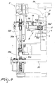
- the center bearing 15 is supported, so that it can rotate about its own axis, by the main supporting structure 2 and the rotation means 9 comprise means for actuating the center bearing 15 with an intermittent motion about its own axis 10 with respect to the main supporting structure 2.
- the center bearing 15 is supported by a quadrangular framework 22, which is arranged on a substantially horizontal plane.
- the framework 22 supports the center bearing 15 by means of three sets of cylindrical bearings, each set being formed by: a lower bearing 23, on which the lower face of the center bearing 15 rests; an upper bearing 24, which rests against the upper face of the center bearing 15; and a lateral bearing 25, which rests against the lateral edge of the center bearing 15.
- the axes of the lower bearing 23 and of the upper bearing 24 are oriented radially with respect to the center bearing 15, while the axis of the lateral bearing 25 is oriented vertically. In this manner, the center bearing 15 is firmly anchored to the framework 22 although it can rotate about its own axis 10 with respect to said framework 22.
- the means for actuating the center bearing 15 with an intermittent motion about its axis 10 comprise a gearmotor 26, which is mounted on the framework 20 and is connected, by means of its output shaft, to the center bearing 15. More particularly, a pinion 27 is keyed to the output shaft of said gearmotor 26 and meshes with a chain 28, which surrounds the center bearing 15 and is fixed thereto at a point 29. In this manner, by actuating the gearmotor 26 it is possible to achieve the rotation of the center bearing 15 about its own axis 10 with respect to the framework 22 through an arc of at least 180°, which allows to perform the entire nailing of the flange 40.
- the framework 22 is supported by the main supporting structure 2 so that it can slide along a vertical direction, and means for translational motion are provided which act on the framework 22 in order to move it vertically, so as to lift or lower the center bearing 15 with respect to the worktable 3.
- the main supporting structure 2 is provided with two vertical shoulders 30a, 30b, to which guiding plates 31a, 31b are fixed; side walls 32a, 32b fixed laterally to the framework 22 mate with the said plates.
- the means for translational motion comprise a shaft 33, which is arranged horizontally and is supported, so that it can rotate about its own axis, by the main supporting structure 2.
- Two gears 34a, 34b are keyed on said shaft 33, which can be turned about its own axis by means of a known type of gearmotor, not shown for the sake of simplicity; said gears mesh with respective racks 35a, 35b, which are arranged vertically and are supported so that they can slide along their extension by the main supporting structure 2.
- These racks 35a, 35b, by means of rods 36a, 36b, are connected to the framework 22 so that an actuation of the shaft 33 with a rotary motion about its own axis in one direction or in the opposite direction causes an upward or downward translational motion of the framework 22.
- the pieces of wood 4 are deposited on the worktable 3 in two superimposed layers, which are offset in a per se known manner and must be nailed in order to produce the flange 40.
- the fluid-operated cylinders 20a, 20b, 21a, 21b are actuated and push the pressers 11 a, 11b, 12a, 12b against the pieces of wood 4, compacting them.
- the nailing clamps 6 are then actuated and cyclically perform a nailing operation and are then raised above the flange 40 being produced. While the nailing clamps 6 are disengaged from the flange 40, the gearmotor 26 is actuated so as to produce the rotation, through a preset angle, of the center bearing 15 and therefore of the flange 40 being nailed, about the axis 10 of said flange 40 with respect to the main supporting structure 2 and therefore with respect to the nailing clamps 6, so as to preset the flange 40 for the subsequent nailing operation.
- the nailing operation of the flange 40 is completed. It should be noted that the rotation of the bearing 15 about its own axis 10 throughout the nailing operation can be performed without disengaging the presser elements 11a, 11b, 12a, 12b from the flange 40, since the particular arrangement of the compaction means 8 in the machine according to the invention excludes any possibility of interference of the compaction means 8 with the nailing clamps 6 even if a large number of nailing clamps 6 is mounted on the machine due to production requirements.
- the pressers 11a, 11b, 12a, 12b are disengaged from the flange 40 and the center bearing 15 is again raised above the worktable 3 in order to allow the manufactured flange 40 to move away and allow the deposition of pieces of wood 4 on the worktable 3 in order to manufacture a new flange.
- the materials used, as well as the dimensions, may be any according to requirements and to the state of the art.
Landscapes
- Engineering & Computer Science (AREA)
- Life Sciences & Earth Sciences (AREA)
- Manufacturing & Machinery (AREA)
- Wood Science & Technology (AREA)
- Forests & Forestry (AREA)
- Dovetailed Work, And Nailing Machines And Stapling Machines For Wood (AREA)
- Portable Nailing Machines And Staplers (AREA)
- Installation Of Indoor Wiring (AREA)
- Manufacture Of Motors, Generators (AREA)
Applications Claiming Priority (1)
| Application Number | Priority Date | Filing Date | Title |
|---|---|---|---|
| IT000743A ITMI20050743A1 (it) | 2005-04-26 | 2005-04-26 | Macchina per la produzione di flange di bobine di avvolgimento per cavi elettrici mediante chiodatura di pezzi di legno |
Publications (2)
| Publication Number | Publication Date |
|---|---|
| EP1716996A1 true EP1716996A1 (de) | 2006-11-02 |
| EP1716996B1 EP1716996B1 (de) | 2008-04-30 |
Family
ID=36754587
Family Applications (1)
| Application Number | Title | Priority Date | Filing Date |
|---|---|---|---|
| EP06006704A Expired - Lifetime EP1716996B1 (de) | 2005-04-26 | 2006-03-30 | Maschine zum Herstellen von Flanschen für Trommeln für elektrische Kabel durch Nageln von Holzteilen |
Country Status (5)
| Country | Link |
|---|---|
| EP (1) | EP1716996B1 (de) |
| AT (1) | ATE393691T1 (de) |
| DE (1) | DE602006001025T2 (de) |
| ES (1) | ES2306318T3 (de) |
| IT (1) | ITMI20050743A1 (de) |
Cited By (2)
| Publication number | Priority date | Publication date | Assignee | Title |
|---|---|---|---|---|
| EP2952309A1 (de) * | 2014-06-04 | 2015-12-09 | CORALI S.p.A. | Nagelmaschine zum nageln von mindestens zwei übereinander angeordneter schichten von streifen |
| EP2952308A1 (de) * | 2014-06-04 | 2015-12-09 | CORALI S.p.A. | Nagelmaschine, insbesondere zur montage von bünden von holzrollen zum aufwickeln von elektrokabeln, stahlkabeln, seilen, glasfaserkabeln oder drahtähnlichen elementen im allgemeinen |
Citations (3)
| Publication number | Priority date | Publication date | Assignee | Title |
|---|---|---|---|---|
| US2008831A (en) * | 1930-03-22 | 1935-07-23 | Kruse Hermann | Method and apparatus for nailing flanges |
| IT1171661B (it) * | 1983-03-11 | 1987-06-10 | Bruno Corali | Macchina chiodatrice automatica, particolarmente per la realizzazione delle fiancate di bobine in legno per cavi elettrici e simili |
| WO1996012595A1 (en) * | 1994-10-19 | 1996-05-02 | Marco Iannucci | An automatic system for the production of wooden spools for winding of electric cables and similar |
-
2005
- 2005-04-26 IT IT000743A patent/ITMI20050743A1/it unknown
-
2006
- 2006-03-30 ES ES06006704T patent/ES2306318T3/es not_active Expired - Lifetime
- 2006-03-30 DE DE602006001025T patent/DE602006001025T2/de not_active Expired - Lifetime
- 2006-03-30 AT AT06006704T patent/ATE393691T1/de not_active IP Right Cessation
- 2006-03-30 EP EP06006704A patent/EP1716996B1/de not_active Expired - Lifetime
Patent Citations (3)
| Publication number | Priority date | Publication date | Assignee | Title |
|---|---|---|---|---|
| US2008831A (en) * | 1930-03-22 | 1935-07-23 | Kruse Hermann | Method and apparatus for nailing flanges |
| IT1171661B (it) * | 1983-03-11 | 1987-06-10 | Bruno Corali | Macchina chiodatrice automatica, particolarmente per la realizzazione delle fiancate di bobine in legno per cavi elettrici e simili |
| WO1996012595A1 (en) * | 1994-10-19 | 1996-05-02 | Marco Iannucci | An automatic system for the production of wooden spools for winding of electric cables and similar |
Cited By (2)
| Publication number | Priority date | Publication date | Assignee | Title |
|---|---|---|---|---|
| EP2952309A1 (de) * | 2014-06-04 | 2015-12-09 | CORALI S.p.A. | Nagelmaschine zum nageln von mindestens zwei übereinander angeordneter schichten von streifen |
| EP2952308A1 (de) * | 2014-06-04 | 2015-12-09 | CORALI S.p.A. | Nagelmaschine, insbesondere zur montage von bünden von holzrollen zum aufwickeln von elektrokabeln, stahlkabeln, seilen, glasfaserkabeln oder drahtähnlichen elementen im allgemeinen |
Also Published As
| Publication number | Publication date |
|---|---|
| ATE393691T1 (de) | 2008-05-15 |
| DE602006001025D1 (de) | 2008-06-12 |
| ITMI20050743A1 (it) | 2006-10-27 |
| EP1716996B1 (de) | 2008-04-30 |
| ES2306318T3 (es) | 2008-11-01 |
| DE602006001025T2 (de) | 2009-06-25 |
Similar Documents
| Publication | Publication Date | Title |
|---|---|---|
| US10240266B2 (en) | Circular knitting machine with an engaging and disengaging mechanism of the hook plate of the dial group | |
| KR101621064B1 (ko) | 프로파일의 펀칭 및 노칭 자동가공장치 | |
| KR101658045B1 (ko) | 과실의 과육과 씨 분리장치 | |
| US4656703A (en) | Machine for producing complex objects by multidirectional deposition of thread | |
| CN111644762A (zh) | 一种卷料自动切割机构 | |
| US20130310236A1 (en) | Press machine die unit replacing device | |
| EP1716996B1 (de) | Maschine zum Herstellen von Flanschen für Trommeln für elektrische Kabel durch Nageln von Holzteilen | |
| EP2004344B1 (de) | Sammel- und zuführvorrichtung für metallstangen | |
| CN115210012A (zh) | 一种用于建筑钢网的弯曲头 | |
| CN114104747B (zh) | 混凝土砌块成型湿法工艺码坯生产工艺及整体旋转机构 | |
| IT201900006414A1 (it) | Macchina sgusciatrice di frutta secca con gruppi di sgusciatura sovrapposti. | |
| EP2952308B1 (de) | Nagelmaschine, insbesondere zur montage von bünden von holzrollen zum aufwickeln von elektrokabeln, stahlkabeln, seilen, glasfaserkabeln oder drahtähnlichen elementen im allgemeinen | |
| CN109435213B (zh) | 一种多层材料热合定型机及其多层材料热合定型工艺 | |
| JP5964413B2 (ja) | 回転プレス機および回転プレス機を作動させる方法 | |
| CN116276010B (zh) | 全自动免拆桁架螺钉装配机 | |
| CN219562105U (zh) | 一种全自动免拆桁架螺钉装配机 | |
| CN111774517B (zh) | 一种梭式送料铆接装置 | |
| KR102401269B1 (ko) | 그린 타이어를 제조하는 장치 및 방법 | |
| CN208055602U (zh) | 转盘式自动收料装置及全自动帽檐缝纫机 | |
| DE463565C (de) | Flecht- und Kloeppelmaschine zur Herstellung von Litzen aus Textilfaeden oder bzw. und Metalldraehten mit zwei in entgegengesetzten Richtungen drehbaren Spulenreihen | |
| EP2433770B1 (de) | Nagelmaschine für Montage von Paletten aus Holz oder dergleichen mit hoher Anwendungsflexibilität | |
| CN114367601B (zh) | 一种全自动冲簧机 | |
| US765664A (en) | Cotton-press. | |
| US877151A (en) | Machine for slitting plastic tubes. | |
| DE99291C (de) |
Legal Events
| Date | Code | Title | Description |
|---|---|---|---|
| PUAI | Public reference made under article 153(3) epc to a published international application that has entered the european phase |
Free format text: ORIGINAL CODE: 0009012 |
|
| AK | Designated contracting states |
Kind code of ref document: A1 Designated state(s): AT BE BG CH CY CZ DE DK EE ES FI FR GB GR HU IE IS IT LI LT LU LV MC NL PL PT RO SE SI SK TR |
|
| AX | Request for extension of the european patent |
Extension state: AL BA HR MK YU |
|
| 17P | Request for examination filed |
Effective date: 20070426 |
|
| AKX | Designation fees paid |
Designated state(s): AT BE BG CH CY CZ DE DK EE ES FI FR GB GR HU IE IS IT LI LT LU LV MC NL PL PT RO SE SI SK TR |
|
| GRAP | Despatch of communication of intention to grant a patent |
Free format text: ORIGINAL CODE: EPIDOSNIGR1 |
|
| GRAS | Grant fee paid |
Free format text: ORIGINAL CODE: EPIDOSNIGR3 |
|
| GRAA | (expected) grant |
Free format text: ORIGINAL CODE: 0009210 |
|
| AK | Designated contracting states |
Kind code of ref document: B1 Designated state(s): AT BE BG CH CY CZ DE DK EE ES FI FR GB GR HU IE IS IT LI LT LU LV MC NL PL PT RO SE SI SK TR |
|
| REG | Reference to a national code |
Ref country code: GB Ref legal event code: FG4D |
|
| REG | Reference to a national code |
Ref country code: CH Ref legal event code: EP |
|
| REG | Reference to a national code |
Ref country code: IE Ref legal event code: FG4D Free format text: LANGUAGE OF EP DOCUMENT: FRENCH |
|
| REF | Corresponds to: |
Ref document number: 602006001025 Country of ref document: DE Date of ref document: 20080612 Kind code of ref document: P |
|
| REG | Reference to a national code |
Ref country code: SE Ref legal event code: TRGR |
|
| PG25 | Lapsed in a contracting state [announced via postgrant information from national office to epo] |
Ref country code: SI Free format text: LAPSE BECAUSE OF FAILURE TO SUBMIT A TRANSLATION OF THE DESCRIPTION OR TO PAY THE FEE WITHIN THE PRESCRIBED TIME-LIMIT Effective date: 20080430 |
|
| PG25 | Lapsed in a contracting state [announced via postgrant information from national office to epo] |
Ref country code: PT Free format text: LAPSE BECAUSE OF FAILURE TO SUBMIT A TRANSLATION OF THE DESCRIPTION OR TO PAY THE FEE WITHIN THE PRESCRIBED TIME-LIMIT Effective date: 20080930 Ref country code: BG Free format text: LAPSE BECAUSE OF FAILURE TO SUBMIT A TRANSLATION OF THE DESCRIPTION OR TO PAY THE FEE WITHIN THE PRESCRIBED TIME-LIMIT Effective date: 20080730 |
|
| REG | Reference to a national code |
Ref country code: ES Ref legal event code: FG2A Ref document number: 2306318 Country of ref document: ES Kind code of ref document: T3 |
|
| PG25 | Lapsed in a contracting state [announced via postgrant information from national office to epo] |
Ref country code: AT Free format text: LAPSE BECAUSE OF FAILURE TO SUBMIT A TRANSLATION OF THE DESCRIPTION OR TO PAY THE FEE WITHIN THE PRESCRIBED TIME-LIMIT Effective date: 20080430 Ref country code: LV Free format text: LAPSE BECAUSE OF FAILURE TO SUBMIT A TRANSLATION OF THE DESCRIPTION OR TO PAY THE FEE WITHIN THE PRESCRIBED TIME-LIMIT Effective date: 20080430 Ref country code: PL Free format text: LAPSE BECAUSE OF FAILURE TO SUBMIT A TRANSLATION OF THE DESCRIPTION OR TO PAY THE FEE WITHIN THE PRESCRIBED TIME-LIMIT Effective date: 20080430 |
|
| PG25 | Lapsed in a contracting state [announced via postgrant information from national office to epo] |
Ref country code: IS Free format text: LAPSE BECAUSE OF FAILURE TO SUBMIT A TRANSLATION OF THE DESCRIPTION OR TO PAY THE FEE WITHIN THE PRESCRIBED TIME-LIMIT Effective date: 20080830 |
|
| ET | Fr: translation filed | ||
| PG25 | Lapsed in a contracting state [announced via postgrant information from national office to epo] |
Ref country code: LT Free format text: LAPSE BECAUSE OF FAILURE TO SUBMIT A TRANSLATION OF THE DESCRIPTION OR TO PAY THE FEE WITHIN THE PRESCRIBED TIME-LIMIT Effective date: 20080430 Ref country code: CZ Free format text: LAPSE BECAUSE OF FAILURE TO SUBMIT A TRANSLATION OF THE DESCRIPTION OR TO PAY THE FEE WITHIN THE PRESCRIBED TIME-LIMIT Effective date: 20080430 Ref country code: DK Free format text: LAPSE BECAUSE OF FAILURE TO SUBMIT A TRANSLATION OF THE DESCRIPTION OR TO PAY THE FEE WITHIN THE PRESCRIBED TIME-LIMIT Effective date: 20080430 |
|
| PG25 | Lapsed in a contracting state [announced via postgrant information from national office to epo] |
Ref country code: SK Free format text: LAPSE BECAUSE OF FAILURE TO SUBMIT A TRANSLATION OF THE DESCRIPTION OR TO PAY THE FEE WITHIN THE PRESCRIBED TIME-LIMIT Effective date: 20080430 Ref country code: BE Free format text: LAPSE BECAUSE OF FAILURE TO SUBMIT A TRANSLATION OF THE DESCRIPTION OR TO PAY THE FEE WITHIN THE PRESCRIBED TIME-LIMIT Effective date: 20080430 Ref country code: RO Free format text: LAPSE BECAUSE OF FAILURE TO SUBMIT A TRANSLATION OF THE DESCRIPTION OR TO PAY THE FEE WITHIN THE PRESCRIBED TIME-LIMIT Effective date: 20080430 |
|
| PLBE | No opposition filed within time limit |
Free format text: ORIGINAL CODE: 0009261 |
|
| STAA | Information on the status of an ep patent application or granted ep patent |
Free format text: STATUS: NO OPPOSITION FILED WITHIN TIME LIMIT |
|
| 26N | No opposition filed |
Effective date: 20090202 |
|
| PG25 | Lapsed in a contracting state [announced via postgrant information from national office to epo] |
Ref country code: EE Free format text: LAPSE BECAUSE OF FAILURE TO SUBMIT A TRANSLATION OF THE DESCRIPTION OR TO PAY THE FEE WITHIN THE PRESCRIBED TIME-LIMIT Effective date: 20080430 |
|
| PG25 | Lapsed in a contracting state [announced via postgrant information from national office to epo] |
Ref country code: MC Free format text: LAPSE BECAUSE OF NON-PAYMENT OF DUE FEES Effective date: 20090331 |
|
| REG | Reference to a national code |
Ref country code: IE Ref legal event code: MM4A |
|
| PG25 | Lapsed in a contracting state [announced via postgrant information from national office to epo] |
Ref country code: IE Free format text: LAPSE BECAUSE OF NON-PAYMENT OF DUE FEES Effective date: 20090330 |
|
| PG25 | Lapsed in a contracting state [announced via postgrant information from national office to epo] |
Ref country code: GR Free format text: LAPSE BECAUSE OF FAILURE TO SUBMIT A TRANSLATION OF THE DESCRIPTION OR TO PAY THE FEE WITHIN THE PRESCRIBED TIME-LIMIT Effective date: 20080731 |
|
| REG | Reference to a national code |
Ref country code: CH Ref legal event code: PL |
|
| GBPC | Gb: european patent ceased through non-payment of renewal fee |
Effective date: 20100330 |
|
| PG25 | Lapsed in a contracting state [announced via postgrant information from national office to epo] |
Ref country code: CH Free format text: LAPSE BECAUSE OF NON-PAYMENT OF DUE FEES Effective date: 20100331 Ref country code: LI Free format text: LAPSE BECAUSE OF NON-PAYMENT OF DUE FEES Effective date: 20100331 |
|
| PG25 | Lapsed in a contracting state [announced via postgrant information from national office to epo] |
Ref country code: GB Free format text: LAPSE BECAUSE OF NON-PAYMENT OF DUE FEES Effective date: 20100330 |
|
| PG25 | Lapsed in a contracting state [announced via postgrant information from national office to epo] |
Ref country code: LU Free format text: LAPSE BECAUSE OF NON-PAYMENT OF DUE FEES Effective date: 20090330 |
|
| PG25 | Lapsed in a contracting state [announced via postgrant information from national office to epo] |
Ref country code: HU Free format text: LAPSE BECAUSE OF FAILURE TO SUBMIT A TRANSLATION OF THE DESCRIPTION OR TO PAY THE FEE WITHIN THE PRESCRIBED TIME-LIMIT Effective date: 20081101 |
|
| PG25 | Lapsed in a contracting state [announced via postgrant information from national office to epo] |
Ref country code: TR Free format text: LAPSE BECAUSE OF FAILURE TO SUBMIT A TRANSLATION OF THE DESCRIPTION OR TO PAY THE FEE WITHIN THE PRESCRIBED TIME-LIMIT Effective date: 20080430 |
|
| PG25 | Lapsed in a contracting state [announced via postgrant information from national office to epo] |
Ref country code: CY Free format text: LAPSE BECAUSE OF FAILURE TO SUBMIT A TRANSLATION OF THE DESCRIPTION OR TO PAY THE FEE WITHIN THE PRESCRIBED TIME-LIMIT Effective date: 20080430 |
|
| PGFP | Annual fee paid to national office [announced via postgrant information from national office to epo] |
Ref country code: FI Payment date: 20120320 Year of fee payment: 7 Ref country code: IT Payment date: 20120322 Year of fee payment: 7 Ref country code: SE Payment date: 20120322 Year of fee payment: 7 |
|
| PGFP | Annual fee paid to national office [announced via postgrant information from national office to epo] |
Ref country code: DE Payment date: 20120323 Year of fee payment: 7 Ref country code: NL Payment date: 20120403 Year of fee payment: 7 |
|
| PGFP | Annual fee paid to national office [announced via postgrant information from national office to epo] |
Ref country code: FR Payment date: 20120418 Year of fee payment: 7 |
|
| PGFP | Annual fee paid to national office [announced via postgrant information from national office to epo] |
Ref country code: ES Payment date: 20120329 Year of fee payment: 7 |
|
| REG | Reference to a national code |
Ref country code: NL Ref legal event code: V1 Effective date: 20131001 |
|
| REG | Reference to a national code |
Ref country code: SE Ref legal event code: EUG |
|
| PG25 | Lapsed in a contracting state [announced via postgrant information from national office to epo] |
Ref country code: SE Free format text: LAPSE BECAUSE OF NON-PAYMENT OF DUE FEES Effective date: 20130331 Ref country code: FI Free format text: LAPSE BECAUSE OF NON-PAYMENT OF DUE FEES Effective date: 20130330 |
|
| REG | Reference to a national code |
Ref country code: FR Ref legal event code: ST Effective date: 20131129 |
|
| REG | Reference to a national code |
Ref country code: DE Ref legal event code: R119 Ref document number: 602006001025 Country of ref document: DE Effective date: 20131001 |
|
| PG25 | Lapsed in a contracting state [announced via postgrant information from national office to epo] |
Ref country code: DE Free format text: LAPSE BECAUSE OF NON-PAYMENT OF DUE FEES Effective date: 20131001 Ref country code: FR Free format text: LAPSE BECAUSE OF NON-PAYMENT OF DUE FEES Effective date: 20130402 |
|
| PG25 | Lapsed in a contracting state [announced via postgrant information from national office to epo] |
Ref country code: IT Free format text: LAPSE BECAUSE OF NON-PAYMENT OF DUE FEES Effective date: 20130330 Ref country code: NL Free format text: LAPSE BECAUSE OF NON-PAYMENT OF DUE FEES Effective date: 20131001 |
|
| REG | Reference to a national code |
Ref country code: ES Ref legal event code: FD2A Effective date: 20140610 |
|
| PG25 | Lapsed in a contracting state [announced via postgrant information from national office to epo] |
Ref country code: ES Free format text: LAPSE BECAUSE OF NON-PAYMENT OF DUE FEES Effective date: 20130331 |
|
| P01 | Opt-out of the competence of the unified patent court (upc) registered |
Effective date: 20230529 |