EP1719991A1 - Torque meter - Google Patents
Torque meter Download PDFInfo
- Publication number
- EP1719991A1 EP1719991A1 EP04708059A EP04708059A EP1719991A1 EP 1719991 A1 EP1719991 A1 EP 1719991A1 EP 04708059 A EP04708059 A EP 04708059A EP 04708059 A EP04708059 A EP 04708059A EP 1719991 A1 EP1719991 A1 EP 1719991A1
- Authority
- EP
- European Patent Office
- Prior art keywords
- torque
- load
- elastic member
- meter according
- detection means
- Prior art date
- Legal status (The legal status is an assumption and is not a legal conclusion. Google has not performed a legal analysis and makes no representation as to the accuracy of the status listed.)
- Withdrawn
Links
Images


Classifications
-
- G—PHYSICS
- G01—MEASURING; TESTING
- G01L—MEASURING FORCE, STRESS, TORQUE, WORK, MECHANICAL POWER, MECHANICAL EFFICIENCY, OR FLUID PRESSURE
- G01L3/00—Measuring torque, work, mechanical power, or mechanical efficiency, in general
- G01L3/02—Rotary-transmission dynamometers
- G01L3/14—Rotary-transmission dynamometers wherein the torque-transmitting element is other than a torsionally-flexible shaft
- G01L3/1407—Rotary-transmission dynamometers wherein the torque-transmitting element is other than a torsionally-flexible shaft involving springs
- G01L3/1428—Rotary-transmission dynamometers wherein the torque-transmitting element is other than a torsionally-flexible shaft involving springs using electrical transducers
- G01L3/1457—Rotary-transmission dynamometers wherein the torque-transmitting element is other than a torsionally-flexible shaft involving springs using electrical transducers involving resistance strain gauges
Definitions
- the present invention relates to torque meters for measuring a driving torque produced on an output shaft of rotary drive units such as an electric motor and a reduction gear.
- a torque meter of this type serves to measure a moment for a shaft such as a rotary shaft or a stationary shaft as center.
- detection of torque is made by detecting a torsional force of the shaft produced by torque or a torsional angle of the shaft changed by torque.
- a means for detecting the torsional force means is known which uses a piezoelectric element for generating an electric charge proportional to the force received.
- a magnetostrictive element which is an element using a material having magnetic characteristics that change when subject to a force, serves to detect torque as force.
- a distortion-gage system and a rotation pulse phase difference system are well known. It can detect a minute torsional angle of the shaft as a minute displacement.
- Japanese Unexamined Patent Application 2003-083824 discloses a torque meter.
- the torque meter includes a platelike elastic body mounted between a flange provided to a rotary drive unit and a rotary driven structure, and has a plurality of circular holes formed in a torque transfer area.
- a flange fixing part arranged around a central through hole and having a fastening means with the flange is connected to a base fixing part arranged outside the flange fixing part and having a fastening means for a fixing base of the rotary driven structure.
- a distortion gauge is bonded on the interior surface of each circular hole to measure distortion due to torque acting on the torque transfer area, thus detecting a driving torque produced on an output shaft.
- Japanese Unexamined Patent Application 53-106181 proposes that a plurality of sensors are mounted in the differential-sensor structure for torque detection, in which the sensors are added to increase an output with regard to torque, and the sensors are subtracted to reduce an output with regard to changes other than torque.
- Japanese Unexamined Patent Application 53-106181 can reduce the influence other than torque by virtue of the actuation structure, influences due to sensor-to-sensor unbalance, structural unbalance, etc. had to be removed to sufficiently reduce the influence, raising a problem of difficulties in the manufacturing process.
- An object of the present invention is to provide a torque meter that allows accurate torque measurement by detecting only torque, without being affected by the aforementioned various loads, ideally, without any influences other than torque.
- the first aspect of the invention is a torque meter including an elastic member arranged in a power transmission channel and which deforms in response to torque to be measured, and a torque detection means for detecting the torque based on the deformation of the elastic member, characterized in that it includes a torque member for receiving the torque applied to the elastic member, and a load member arranged separately from the torque member, for supporting a load of the elastic member.
- the elastic member includes an input part, an output part, and a deforming part arranged between said input part and said output part, and that the torque member and the load member are formed with the deforming part.
- the elastic member includes a flange-type member, that the torque member and said load member include thin parts formed with said elastic member, that said torque member has a direction of a surface of the thin part positioned parallel to a torque direction, and that said load member has a direction of a thickness of the thin part positioned parallel to the torque direction.
- the elastic member includes a torsion-bar-type member, that the torque member includes a small-diameter shaft part, and that the load member includes a thin part formed in a radial direction of said small-diameter shaft part and having a direction of a surface positioned in a direction of a torsional moment.
- the elastic member includes a cylindrical member, that the torque member includes a thin part arranged in a circular-arc direction, and that the load member includes a thin part arranged in a radial direction.
- torque detection means are mounted to at least one of the torque member and said load member.
- a seventh aspect of the torque meter as described in any one of the first to sixth aspect of the present inventions characterized in that the torque detection means uses two or more types of means.
- the present invention produces the following effects:
- the present invention achieves an object for detecting torque alone with a high accuracy, and without being affected by various loads by separating a torque member and a load member.
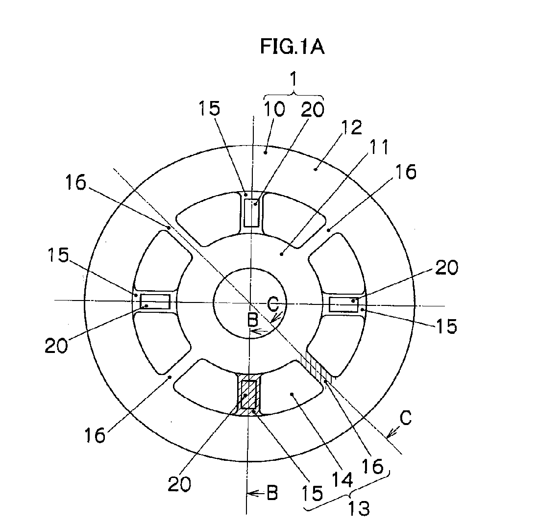
- FIG. 1A to 1C are views showing embodiment 1 of the torque meter according to the present invention.
- a torque meter 1 in the embodiment 1 is arranged in a power transmission channel, and includes an elastic member 10 that deforms in response to a torque to be measured and torque detection means 20 for detecting a torque based on deformation of the elastic member 10.
- the elastic member 10 is arranged between a main-body part and a fixing part of a rotary drive unit (not shown).
- the elastic member 10 is made of a metal such as aluminum, and includes a flange-type member having a specific thickness and upper and lower surfaces arranged parallel to each other.
- the elastic member 10 includes a first fixing part (input part) 11 fixed to the main-body part of the rotary drive unit, a second fixing part (output part) 12 fixed to the fixing part of the rotary drive unit, and a deforming part 13 arranged between the first and second fixing parts 11 and 12.
- the deforming part 13 is formed with a plurality of (here, eight) holes 14, wherein connections between the holes 14 include a torque member 15 and a load member 16 alternately.
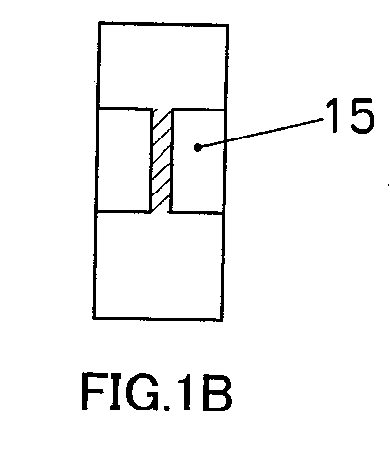
- the torque member 15 is a portion for receiving a torque to be applied to the elastic member 10, and includes, as shown in FIG. 1B, a thin part having the surface which is positioned parallel to the torque direction of the elastic member 10.
- the load member 16 which is arranged separate from the torque member 15, is a portion for supporting a load of the elastic member 10, and includes a thin part having a direction of a thickness which is positioned parallel to the direction of the torque of the elastic member 10.
- each torque detection means 20 is configured by placing a distortion gauge on a torque member 15, and detects a torque with the conventional differential-sensor structure.
- the torque detection means 20 such as a distortion gauge or the like are mounted to the torque member 15. Optionally, they may be mounted to portion different from the torque member or may be placed only on some of the torque member 15.
- FIG. 2A and 2B are views showing the direction that the torque member and load member of the torque meter according to the embodiment 1 receive loads.
- FIG. 3 is a view showing the direction of deformation of the torque member of the torque meter according to the embodiment 1.
- FIG. 4 is a view showing the direction of deformation of the load member of the torque meter according to the embodiment 1.
- FIG. 5A to 5D are schematic views showing an acting manner of a torque and a load of the torque member and load member of the torque meter according to the embodiment 1.
- the torque member 15 and load member 16 are rectangular parallelepipeds having the same cross-sectional area and the same length-to-width ratio (suppose that the length-to-width ratio is 1:5, for example), it can be considered that the difference between the torque member 15 and the load member 16 results from the difference in direction of a force received. It is noted that the radial direction is not considered here since the torque member 15 and load member 16 are equal with respect to the radial direction.
- the torque member 15 shares a torque corresponding load 25 times greater than the load member 16. Therefore, an internal stress occurs, allowing measurement of distortion with excellent sensitivity.
- the torque member 15 shares 1/25 (ratio of a secondary sectional moment) of a load of the load member 16.
- the torque meter 1 in the embodiment 1 allows intentional selection of a force to be received by suitably aligning the sectional shapes of the torque member 15 and load member 16 in the load direction.
- the load member can appropriately be positioned in accordance with other load capabilities as required.
- the torque meter 1 is configured by structurally separating the torque member 15 that is a member for receiving a torque and other member such as load member 16 that is a member for receiving a load, supporting loads separately from a torque. Thus, their influences on torque can further be reduced.
- FIG. 6 is a view showing embodiment 2 of the torque meter according to the present invention.
- a deforming part 13B is formed with eight grooves 14B, wherein connections between the grooves 14B include torque member 15 and load member 16 alternately.
- the groove structures 14B will serve as a guide so that an effect of reducing danger and damage can be expected. Moreover, by changing the holes 14 in the embodiment 1 to the structure of the grooves 14B in the embodiment 2, the execution methods can also be changed, which can be selected as appropriate.
- FIG. 7 is a view showing embodiment 3 of the torque meter according to the present invention.
- a deforming part 13C is formed with four grooves 14C, in which connections between the grooves 14C include two load members 16C and 16C and one torque member 15C held therebetween.
- the number of torque members and load members may be different.
- the number of load members can be selected in accordance with the magnitude of loads other than torque.
- FIG. 8 is a view showing embodiment 4 of the torque meter according to the present invention.
- a deforming part 13D is formed with eight grooves 14D, wherein connections between the grooves 14D include a torque member 15D and a load member 16D alternately.
- torque detection means 21 and 22, which are different, are further provided to the torque member 15D and the load member 16D.
- the torque detection means 21 Using a distortion gauge as the torque detection means 21 and a capacitance-type sensor of excellent responsivity as the torque detection means 22, for example, signals of any one of the sensors can be used in accordance with the purpose.
- the torque detection means can be selected as appropriate in accordance with the use. For example, when the responsiveness is required, in contrast the stability (noise and temperature characteristics) is not so required, or when the responsiveness is not so required, in contrast the stability is required.
- the torque detection means 21 and 22 are mounted to both the torque member 15D and the load member 16D to thereby allow the use of signals of the latter as torque correction signals, leading to a possible enhancement in accuracy.
- FIG. 9A to 9C are views showing embodiment 5 of the torque meter according to the present invention.
- a torque meter 3 in the embodiment 5 includes a flange-type elastic member 30 arranged in the power transmission channel and which deforms in response to a torque to be measured.
- the elastic member 30 is made of metal such as aluminum, and includes a wheel-like member having a predetermined thickness and upper and lower surfaces arranged parallel to each other.
- the elastic member 30 includes a first fixing part (input shaft) 31 fixed to a main-body part of the rotary drive unit, a second fixing part (output shaft) 32 fixed to the stationary part of the rotary drive unit, and a deforming part 33 arranged between the first and second fixing parts 31 and 32.
- the deforming part 33 includes a torque member 35 and a load member 36 arranged alternately in a spoke-like manner.
- the torque member 35 include, as shown in FIG. 9B, a thin part having the direction of the surface which is positioned parallel to the torque direction of the elastic member 30.
- the load member 36 includes, as shown in FIG. 9C, a thin part having the direction of the thickness which is positioned parallel to the torque direction.
- Torque detection means 40 include a distortion gauge placed on the torque member 35.
- FIG. 10A and 10B are views showing embodiment 6 of the torque meter according to the present invention.
- a torque meter 3B in the embodiment 6 is similar to that in the embodiment 5 in that a deforming part 33B of a flange-type elastic member 30B connects a first fixing part 31 to a second fixing part 32 by a torque member 35B and a load member 36B.
- the torque member 35B includes, as shown in FIG. 10B, three thin parts arranged in the tangential direction of the first fixing part 31.
- the load member 36B includes three thin parts arranged in the radial direction of the first fixing part 31.
- the torque detection means 40 include a distortion gauge placed on the torque member 35B.
- FIG. 11A and 11B are views showing embodiment 7 of the torque meter according to the present invention.
- a torque meter 5 in the embodiment 7 is arranged in the power transmission channel, and includes a torsion-bar-type elastic member 50 that deforms in response to a torque to be measured.
- the elastic member 50 is made of metal such as aluminum, and includes a shaft member having a predetermined diameter.
- the elastic member 50 includes, as shown in FIG. 11A, a first fixing part (input shaft) 51, a second fixing part (output shaft) 52, and a deforming part 53 arranged between the first and second fixing parts 51 and 52.
- the deforming part 53 is formed with four cuts 54 as shown in FIG. 11B.
- a torque member 55 includes a small-diameter shaft part.
- a load member 56 includes a thin part arranged in the radial direction of the torque member 55 and having the direction of the thickness which is positioned parallel to the direction of torque.
- Torque detection means 60 are configured to detect encoder disks 61 and 62 arranged at the input and output of the elastic member 50 through non-contact sensors 63 and 64.
- FIG. 12A and 12B are views showing embodiment 8 of the torque meter according to the present invention.
- a torque meter 7 in the embodiment 8 is arranged in the power transmission channel, and includes a cylindrical elastic member 70 that deforms in response to a torque to be measured.
- the elastic member 70 includes, as shown in FIG. 12A, a disk-like first fixing part (input shaft) 71, a disk-like second fixing part (output shaft) 72, and a deforming part 73 arranged between the first and second fixing parts 71 and 72.
- a torque member 75 includes four thin parts that are sections of a cylinder.
- a load member 76 includes a small-thickness part arranged in the radial direction.
- Torque detection means 80 include a distortion gauge placed on the torque member 75.
- the embodiments 5 to 8 have manufacturing and working methods that vary in accordance with the difference in structure, and thus can be selected as appropriate in consideration of performance, cost, etc.
- the embodiment 7 allows a reduction in shaft outer diameter in terms of the structure and thus a reduction in moment of inertia, providing availability when intending to reduce an influence of a moment of inertia.
Landscapes
- Physics & Mathematics (AREA)
- General Physics & Mathematics (AREA)
- Force Measurement Appropriate To Specific Purposes (AREA)
Abstract
Description
- The present invention relates to torque meters for measuring a driving torque produced on an output shaft of rotary drive units such as an electric motor and a reduction gear.
- A torque meter of this type serves to measure a moment for a shaft such as a rotary shaft or a stationary shaft as center.
- Typically, detection of torque is made by detecting a torsional force of the shaft produced by torque or a torsional angle of the shaft changed by torque. As a means for detecting the torsional force, means is known which uses a piezoelectric element for generating an electric charge proportional to the force received. Moreover, a magnetostrictive element, which is an element using a material having magnetic characteristics that change when subject to a force, serves to detect torque as force. On the other hand, as a means for detecting torsional angle, a distortion-gage system and a rotation pulse phase difference system are well known. It can detect a minute torsional angle of the shaft as a minute displacement.
-
Japanese Unexamined Patent Application 2003-083824 - However, with the torque meter as shown in
Japanese Unexamined Patent Application 2003-083824 - Therefore, in order to avoid the influence of forces other than torque, a device is needed to prevent the aforementioned torsional force or torsional angle from being affected by those loads.
- In order to prevent the influence of forces other than torque,
Japanese Unexamined Patent Application 53-106181 - However, although
Japanese Unexamined Patent Application 53-106181 - An object of the present invention is to provide a torque meter that allows accurate torque measurement by detecting only torque, without being affected by the aforementioned various loads, ideally, without any influences other than torque.
- In order to solve the aforementioned problem, the first aspect of the invention is a torque meter including an elastic member arranged in a power transmission channel and which deforms in response to torque to be measured, and a torque detection means for detecting the torque based on the deformation of the elastic member, characterized in that it includes a torque member for receiving the torque applied to the elastic member, and a load member arranged separately from the torque member, for supporting a load of the elastic member.
- In a second aspect of the torque meter as described in the first aspect of the present invention, characterized in that the elastic member includes an input part, an output part, and a deforming part arranged between said input part and said output part, and that the torque member and the load member are formed with the deforming part.
- In a third aspect of the torque meter as described in the first or second aspect of the present invention, characterized in that the elastic member includes a flange-type member, that the torque member and said load member include thin parts formed with said elastic member, that said torque member has a direction of a surface of the thin part positioned parallel to a torque direction, and that said load member has a direction of a thickness of the thin part positioned parallel to the torque direction.
- In a fourth aspect of the torque meter as described in the first or second aspect of the present invention, characterized in that the elastic member includes a torsion-bar-type member, that the torque member includes a small-diameter shaft part, and that the load member includes a thin part formed in a radial direction of said small-diameter shaft part and having a direction of a surface positioned in a direction of a torsional moment.
- In a fifth aspect of the torque meter as described in the first or second aspect of the present invention, characterized in that the elastic member includes a cylindrical member, that the torque member includes a thin part arranged in a circular-arc direction, and that the load member includes a thin part arranged in a radial direction.
- In a sixth aspect of the torque meter as described in any one of the first to fifth aspect of the present inventions, characterized in that the torque detection means are mounted to at least one of the torque member and said load member.
- In a seventh aspect of the torque meter as described in any one of the first to sixth aspect of the present inventions, characterized in that the torque detection means uses two or more types of means.
- As described above, the present invention produces the following effects:
- (1) Due to division into the torque member and the load member, loads other than torque can mainly be supported on the load member, exerting less influence on torque. Therefore, a load resistance of the torque detection means of the same torque sensitivity can be increased.
- (2) Since the torque detection means can be mounted to the torque member or a portion other than the torque member, the flexibility of their mounting sites is increased, allowing achievement of the structure that facilitates the manufacture. Moreover, if the torque detection means is mounted to a portion other than the torque member, additional work for reducing variation between the torque members during adjustment becomes easy to carry out, allowing a reduction in unbalance. By mounting the torque detection means to both the torque member and the load member, signals of the latter can be used as torque correction signals, allowing enhancement in accuracy.
- (3) Two or more types of torque detection means can be used. The use of a plurality of types of torque detection means allows their switching in accordance with the purpose or computing/mixing of their signals, leading to more accurate correction of the temperature, etc.
-
- FIG. 1A to 1C are views showing an
embodiment 1 of a torque meter according to the present invention; - FIG. 2A and 2B are views showing the direction that a torque member and load member of the torque meter according to the
embodiment 1 receive loads; - FIG. 3A to 3C are views showing the direction of deformation of the torque member of the torque meter according to the
embodiment 1; - FIG. 4A to 4C are views showing the direction of deformation of the load member of the torque meter according to the
embodiment 1; - FIG. 5A to 5D are schematic views showing an acting manner of a torque and a load in the torque member and load member of the torque meter according to the
embodiment 1; - FIG. 6 is a view showing an embodiment 2 of the torque meter according to the present invention;
- FIG. 7 is a view showing an
embodiment 3 of the torque meter according to the present invention; - FIG. 8 is a view showing an embodiment 4 of the torque meter according to the present invention.
- FIG. 9A to 9C are views showing an
embodiment 5 of the torque meter according to the present invention; - FIG. 10A and 10B are views showing an embodiment 6 of the torque meter according to the present invention;
- FIG. 11A and 11B are views showing an
embodiment 7 of the torque meter according to the present invention; and - FIG. 12A and 12B are views showing an embodiment 8 of the torque meter according to the present invention.
- The present invention achieves an object for detecting torque alone with a high accuracy, and without being affected by various loads by separating a torque member and a load member.
- With reference to the drawings, etc., a further detailed description will be made hereafter by giving the embodiments of the present invention.
- FIG. 1A to 1C are
views showing embodiment 1 of the torque meter according to the present invention. - A
torque meter 1 in theembodiment 1 is arranged in a power transmission channel, and includes anelastic member 10 that deforms in response to a torque to be measured and torque detection means 20 for detecting a torque based on deformation of theelastic member 10. - The
elastic member 10 is arranged between a main-body part and a fixing part of a rotary drive unit (not shown). Theelastic member 10 is made of a metal such as aluminum, and includes a flange-type member having a specific thickness and upper and lower surfaces arranged parallel to each other. - The
elastic member 10 includes a first fixing part (input part) 11 fixed to the main-body part of the rotary drive unit, a second fixing part (output part) 12 fixed to the fixing part of the rotary drive unit, and a deformingpart 13 arranged between the first and second fixingparts - The deforming
part 13 is formed with a plurality of (here, eight) holes 14, wherein connections between theholes 14 include atorque member 15 and aload member 16 alternately. - The
torque member 15 is a portion for receiving a torque to be applied to theelastic member 10, and includes, as shown in FIG. 1B, a thin part having the surface which is positioned parallel to the torque direction of theelastic member 10. - The
load member 16, which is arranged separate from thetorque member 15, is a portion for supporting a load of theelastic member 10, and includes a thin part having a direction of a thickness which is positioned parallel to the direction of the torque of theelastic member 10. - In the
embodiment 1, each torque detection means 20 is configured by placing a distortion gauge on atorque member 15, and detects a torque with the conventional differential-sensor structure. - The torque detection means 20 such as a distortion gauge or the like are mounted to the
torque member 15. Optionally, they may be mounted to portion different from the torque member or may be placed only on some of thetorque member 15. - FIG. 2A and 2B are views showing the direction that the torque member and load member of the torque meter according to the
embodiment 1 receive loads. FIG. 3 is a view showing the direction of deformation of the torque member of the torque meter according to theembodiment 1. FIG. 4 is a view showing the direction of deformation of the load member of the torque meter according to theembodiment 1. - With the
torque member 15, since a torque T and a radial load Ra are applied in the surface direction, and a thrust load S and a moment M are applied in the thickness direction as shown in FIG. 2A, deformation due to the torque T is as shown in FIG. 3A, deformation due to the thrust load S and moment M is as shown FIG. 3B, and deformation due to the radial load Ra is as shown in FIG. 3C. - With the
load member 16, since the torque T is applied in the direction of thickness and the radial load Ra, thrust load S, and moment M are applied in the direction of surface as shown in FIG. 2B; deformation due to the torque T is as shown in FIG. 4A, deformation due to the thrust load S and moment M is as shown in FIG. 4B, and deformation due to the radial road Ra is as shown in FIG. 4C. - FIG. 5A to 5D are schematic views showing an acting manner of a torque and a load of the torque member and load member of the torque meter according to the
embodiment 1. - Assuming that the
torque member 15 andload member 16 are rectangular parallelepipeds having the same cross-sectional area and the same length-to-width ratio (suppose that the length-to-width ratio is 1:5, for example), it can be considered that the difference between thetorque member 15 and theload member 16 results from the difference in direction of a force received. It is noted that the radial direction is not considered here since thetorque member 15 andload member 16 are equal with respect to the radial direction. - Assuming that the rectangular parallelepiped (FIG. 5A) is a beam having both ends fixed, a deflection δ with respect to a load (R) is expressed by the following formula (1):

- Next, a load share ratio is obtained between the
torque member 15 and theload member 16. - When the
torque member 15 andload member 16 exist simultaneously, deflections when applying loads are the same. Assuming that loads shared at that time are R1 and R2, the following formula (2) is formed:
- If E and L are the same, it is expressed by the following formula (3):

- Here, since consideration is made with regard to the rectangular parallelepiped having 1:5 length-to-width ratio as shown in FIG. 5D, a secondary sectional moment is expressed by I-(1/12)bh3, and consequently:


- In the aforementioned example, the
torque member 15 shares a torque corresponding load 25 times greater than theload member 16. Therefore, an internal stress occurs, allowing measurement of distortion with excellent sensitivity. - On the other hand, as for a thrust load and moment, contrary to torque, the
torque member 15shares 1/25 (ratio of a secondary sectional moment) of a load of theload member 16. - As described above, the
torque meter 1 in theembodiment 1 allows intentional selection of a force to be received by suitably aligning the sectional shapes of thetorque member 15 andload member 16 in the load direction. Thus, after suitably aligning thetorque member 15, the load member can appropriately be positioned in accordance with other load capabilities as required. - Therefore, loads other than torque can mainly be supported on the
load member 16, exerting less influence on torque. Therefore, a load resistance of the torque detection means 20 of the same torque sensitivity can be increased. - Specifically, in addition to the actuation-sensor structure, the
torque meter 1 is configured by structurally separating thetorque member 15 that is a member for receiving a torque and other member such asload member 16 that is a member for receiving a load, supporting loads separately from a torque. Thus, their influences on torque can further be reduced. - Moreover, by separating the
torque member 15 and theload member 16, an influence of loads can be reduced, allowing increase in load rigidity only, without changing the torsional amount (without changing the sensitivity with respect to torque). - FIG. 6 is a view showing embodiment 2 of the torque meter according to the present invention.
- It is to be noted that, in the embodiments depicted below, the same numerals or the unified end numerals are given to the parts that fulfill the same function as in the
embodiment 1 described above, and an overlapping description and drawings are omitted as appropriate. - With a
torque meter 1B in the embodiment 2, a deformingpart 13B is formed with eightgrooves 14B, wherein connections between thegrooves 14B includetorque member 15 andload member 16 alternately. - According to the embodiment 2, even if the
torque member 15 and theload member 16 are broken, thegroove structures 14B will serve as a guide so that an effect of reducing danger and damage can be expected. Moreover, by changing theholes 14 in theembodiment 1 to the structure of thegrooves 14B in the embodiment 2, the execution methods can also be changed, which can be selected as appropriate. - FIG. 7 is a
view showing embodiment 3 of the torque meter according to the present invention. - With a
torque meter 1C in theembodiment 3, a deformingpart 13C is formed with fourgrooves 14C, in which connections between thegrooves 14C include twoload members torque member 15C held therebetween. - In such a manner, the number of torque members and load members may be different. Specifically, according to the
embodiment 3, the number of load members can be selected in accordance with the magnitude of loads other than torque. - FIG. 8 is a view showing embodiment 4 of the torque meter according to the present invention.
- With a
torque meter 1D in the embodiment 4, a deformingpart 13D is formed with eightgrooves 14D, wherein connections between thegrooves 14D include atorque member 15D and aload member 16D alternately. - In this embodiment 4, torque detection means 21 and 22, which are different, are further provided to the
torque member 15D and theload member 16D. - Using a distortion gauge as the torque detection means 21 and a capacitance-type sensor of excellent responsivity as the torque detection means 22, for example, signals of any one of the sensors can be used in accordance with the purpose. Specifically, the torque detection means can be selected as appropriate in accordance with the use. For example, when the responsiveness is required, in contrast the stability (noise and temperature characteristics) is not so required, or when the responsiveness is not so required, in contrast the stability is required.
- In the embodiment 4, the torque detection means 21 and 22 are mounted to both the
torque member 15D and theload member 16D to thereby allow the use of signals of the latter as torque correction signals, leading to a possible enhancement in accuracy. - FIG. 9A to 9C are
views showing embodiment 5 of the torque meter according to the present invention. - A
torque meter 3 in theembodiment 5 includes a flange-typeelastic member 30 arranged in the power transmission channel and which deforms in response to a torque to be measured. - The
elastic member 30 is made of metal such as aluminum, and includes a wheel-like member having a predetermined thickness and upper and lower surfaces arranged parallel to each other. - The
elastic member 30 includes a first fixing part (input shaft) 31 fixed to a main-body part of the rotary drive unit, a second fixing part (output shaft) 32 fixed to the stationary part of the rotary drive unit, and a deformingpart 33 arranged between the first and second fixingparts - In the
embodiment 5, the deformingpart 33 includes atorque member 35 and aload member 36 arranged alternately in a spoke-like manner. - The
torque member 35 include, as shown in FIG. 9B, a thin part having the direction of the surface which is positioned parallel to the torque direction of theelastic member 30. Theload member 36 includes, as shown in FIG. 9C, a thin part having the direction of the thickness which is positioned parallel to the torque direction. Torque detection means 40 include a distortion gauge placed on thetorque member 35. - FIG. 10A and 10B are views showing embodiment 6 of the torque meter according to the present invention.
- A
torque meter 3B in the embodiment 6 is similar to that in theembodiment 5 in that a deformingpart 33B of a flange-type elastic member 30B connects a first fixingpart 31 to a second fixingpart 32 by atorque member 35B and aload member 36B. - However, the
torque member 35B includes, as shown in FIG. 10B, three thin parts arranged in the tangential direction of the first fixingpart 31. Theload member 36B includes three thin parts arranged in the radial direction of the first fixingpart 31. The torque detection means 40 include a distortion gauge placed on thetorque member 35B. - FIG. 11A and 11B are
views showing embodiment 7 of the torque meter according to the present invention. - A
torque meter 5 in theembodiment 7 is arranged in the power transmission channel, and includes a torsion-bar-typeelastic member 50 that deforms in response to a torque to be measured. - The
elastic member 50 is made of metal such as aluminum, and includes a shaft member having a predetermined diameter. Theelastic member 50 includes, as shown in FIG. 11A, a first fixing part (input shaft) 51, a second fixing part (output shaft) 52, and a deformingpart 53 arranged between the first and second fixingparts - In the
embodiment 7, the deformingpart 53 is formed with fourcuts 54 as shown in FIG. 11B. Atorque member 55 includes a small-diameter shaft part. Aload member 56 includes a thin part arranged in the radial direction of thetorque member 55 and having the direction of the thickness which is positioned parallel to the direction of torque. - Torque detection means 60 are configured to detect
encoder disks elastic member 50 throughnon-contact sensors - FIG. 12A and 12B are views showing embodiment 8 of the torque meter according to the present invention.
- A
torque meter 7 in the embodiment 8 is arranged in the power transmission channel, and includes a cylindricalelastic member 70 that deforms in response to a torque to be measured. - The
elastic member 70 includes, as shown in FIG. 12A, a disk-like first fixing part (input shaft) 71, a disk-like second fixing part (output shaft) 72, and a deformingpart 73 arranged between the first and second fixingparts - With the deforming
part 73 in the embodiment 8, as shown in FIG. 12B, atorque member 75 includes four thin parts that are sections of a cylinder. Aload member 76 includes a small-thickness part arranged in the radial direction. - Torque detection means 80 include a distortion gauge placed on the
torque member 75. - The
embodiments 5 to 8 have manufacturing and working methods that vary in accordance with the difference in structure, and thus can be selected as appropriate in consideration of performance, cost, etc. By way of example, theembodiment 7 allows a reduction in shaft outer diameter in terms of the structure and thus a reduction in moment of inertia, providing availability when intending to reduce an influence of a moment of inertia. Variation - Without being limited to the embodiments as described above, various changes and modifications are possible, which are also within the scope of equivalents of the present invention.
- (1) The number of torque members and that of load members may be identical or different.
- (2) The torque member and the load member may be connected or may not be connected. Moreover, the torque member and the load member may not be paired.
- (3) There may provide a plurality of torque detection means or a plurality of types of torque detection means. Moreover, the torque detection means may have a load sensor to use its signals as correction signals.
Claims (7)
- A torque meter comprising:an elastic member arranged in a power transmission channel and deforming in response to a torque to be measured; andtorque detection means for detecting the torque based on deformation of said elastic member, characterized in that it comprises:a torque member for receiving the torque applied to said elastic member; anda load member arranged separate from said torque member, for supporting a load of said elastic member.
- The torque meter according to claim 1, characterized in that said elastic member comprises an input part, an output part, and a deforming part arranged between said input part and said output part, and that said torque member and said load member are formed in said deforming part.
- The torque meter according to claim 1 or 2, characterized in that
said elastic member is a flange-type member;
said torque member and said load member are thin parts formed with said elastic member;
said torque member has a direction of a surface of the thin part positioned parallel to a direction; and
said load member has a direction of a thickness of the thin part positioned parallel to the torque direction. - The torque meter according to claims 1 or 2,
characterized in that
said elastic member is a torsion-bar-type member;
said torque member is a small-diameter shaft part; and
said load member is a thin part formed in a radial direction of said small-diameter shaft part and having a direction of a surface positioned in a direction of a torsional moment. - The torque meter according to claim 1 or 2, characterized in that
said elastic member is a cylindrical member;
said torque member is a thin part arranged in a circular-arc direction; and
said load member is a thin part arranged in a radial direction. - The torque meter according to any one of claims 1 to 5,
characterized in that said torque detection means are mounted to at least one of said torque member and said load member. - The torque meter according to any one of claims 1 to 6, characterized in that said torque detection means use two or more types of means.
Applications Claiming Priority (1)
| Application Number | Priority Date | Filing Date | Title |
|---|---|---|---|
| PCT/JP2004/001113 WO2005075950A1 (en) | 2004-02-04 | 2004-02-04 | Torque meter |
Publications (2)
| Publication Number | Publication Date |
|---|---|
| EP1719991A1 true EP1719991A1 (en) | 2006-11-08 |
| EP1719991A4 EP1719991A4 (en) | 2007-04-11 |
Family
ID=34835748
Family Applications (1)
| Application Number | Title | Priority Date | Filing Date |
|---|---|---|---|
| EP04708059A Withdrawn EP1719991A4 (en) | 2004-02-04 | 2004-02-04 | TORQUE MEASURING DEVICE |
Country Status (4)
| Country | Link |
|---|---|
| US (1) | US7520182B2 (en) |
| EP (1) | EP1719991A4 (en) |
| JP (1) | JP4368353B2 (en) |
| WO (1) | WO2005075950A1 (en) |
Cited By (4)
| Publication number | Priority date | Publication date | Assignee | Title |
|---|---|---|---|---|
| NL1037563C2 (en) * | 2009-12-16 | 2011-06-20 | Idbike B V | Measuring device for measuring a pedalling force exerted by a cyclist. |
| EP3109610A1 (en) * | 2015-06-26 | 2016-12-28 | Dr. Fritz Faulhaber GmbH & Co. KG | Transmission for small and miniature drive with torque measuring member |
| EP3553485A4 (en) * | 2016-12-07 | 2020-08-19 | Nidec Copal Electronics Corporation | TORQUE SENSOR |
| US11051898B2 (en) * | 2014-02-07 | 2021-07-06 | Covidien Lp | Robotic surgical assemblies and adapter assemblies thereof |
Families Citing this family (34)
| Publication number | Priority date | Publication date | Assignee | Title |
|---|---|---|---|---|
| GB2436149B (en) * | 2006-03-15 | 2011-08-17 | Transense Technologies Plc | Torque measurement in flexible drive coupling plate |
| US7770471B2 (en) | 2004-08-16 | 2010-08-10 | Transense Technologies Plc | Torque measurement within a powertrain |
| US8015886B2 (en) | 2004-08-16 | 2011-09-13 | Transense Technologies Plc | Torque measurement within a powertrain |
| FI118979B (en) * | 2005-04-29 | 2008-05-30 | Metso Automation Oy | Procedure for measuring consistency, circuit breaker design and consistency meter |
| DE102007005894A1 (en) * | 2006-06-14 | 2007-12-20 | GIF Gesellschaft für Industrieforschung mbH | torque flange |
| JP2009288198A (en) * | 2008-05-30 | 2009-12-10 | Sony Corp | Torque measuring device and actuator drive control system |
| DE102009014284B4 (en) | 2009-03-25 | 2017-01-26 | Hottinger Baldwin Messtechnik Gmbh | torque sensor |
| DE102010034877A1 (en) * | 2009-08-23 | 2011-02-24 | GIF Gesellschaft für Industrieforschung mbH | Torque measuring device and arrangement of a torque measuring device and a drive shaft |
| DE102009057810A1 (en) * | 2009-12-10 | 2011-06-16 | Leopold Kostal Gmbh & Co. Kg | Torsion module for torque detection device of e.g. steering system of motor vehicle, has spoked wheel comprising inner ring fastened to steering shaft, and annular disks that are connected with each other made of sheet metal |
| DE102011000054B4 (en) * | 2011-01-07 | 2014-12-11 | Deutsches Zentrum für Luft- und Raumfahrt e.V. | torsion sensor |
| DE102011104286A1 (en) * | 2011-06-16 | 2012-12-20 | Leopold Kostal Gmbh & Co. Kg | Torsion module for torque detection device of steering force support system used in motor car, has torsion bars that are arranged in parallel to each other and are arranged in parallel to rotational axis of steering shaft |
| JP5817371B2 (en) * | 2011-09-15 | 2015-11-18 | トヨタ自動車株式会社 | Torque measuring device |
| EP2790003B1 (en) * | 2011-12-07 | 2019-03-20 | National University Corporation Shizuoka University | Tensile testing machine |
| GB2511101B (en) * | 2013-02-22 | 2017-05-10 | Transense Tech Plc | Torque measurement flexplates |
| CN104316241A (en) * | 2014-11-18 | 2015-01-28 | 北京邮电大学 | Small torque sensor |
| US9751220B2 (en) * | 2015-03-31 | 2017-09-05 | Google Inc. | Flexure based torque sensor |
| JP6092326B2 (en) * | 2015-07-29 | 2017-03-08 | 株式会社トライフォース・マネジメント | Torque sensor |
| JP6525940B2 (en) * | 2015-11-18 | 2019-06-05 | キヤノン株式会社 | Sensor, drive mechanism, and robot |
| JP2017172983A (en) * | 2016-03-18 | 2017-09-28 | 株式会社安川電機 | Robot and torque sensor |
| DE202016008595U1 (en) * | 2016-10-17 | 2018-07-26 | Franka Emlka Gmbh | Torque sensor device for detecting torques |
| JP6935602B2 (en) * | 2016-12-07 | 2021-09-15 | 日本電産コパル電子株式会社 | Torque sensor |
| WO2018124081A1 (en) * | 2016-12-27 | 2018-07-05 | 第一精工株式会社 | Torque sensor |
| TWI628898B (en) * | 2016-12-29 | 2018-07-01 | 財團法人工業技術研究院 | Interaction force detection apparatus |
| JP6549687B2 (en) * | 2017-04-10 | 2019-07-24 | ファナック株式会社 | Torque sensor and robot |
| JP6976892B2 (en) * | 2018-03-29 | 2021-12-08 | 日本電産コパル電子株式会社 | Torque sensor |
| JP6910990B2 (en) * | 2018-07-02 | 2021-07-28 | 日本電産コパル電子株式会社 | Torque sensor support device |
| JP7091177B2 (en) * | 2018-07-13 | 2022-06-27 | 日本電産コパル電子株式会社 | Torque sensor |
| CN109813475B (en) * | 2019-03-29 | 2025-05-02 | 溱者(上海)智能科技有限公司 | A structural component and overload protection mechanism of a torque measuring device |
| JP7090264B2 (en) * | 2019-05-09 | 2022-06-24 | 株式会社テック技販 | Torque measuring device |
| CN112050979B (en) * | 2019-06-06 | 2022-07-29 | 日本电产新宝株式会社 | Torque detection sensor, power transmission device and robot |
| JP1667822S (en) * | 2019-11-29 | 2020-09-07 | ||
| JP1667823S (en) * | 2019-11-29 | 2020-09-07 | ||
| US11892364B2 (en) | 2022-02-10 | 2024-02-06 | Ati Industrial Automation, Inc. | Torque sensor using coupled loads and fewer strain gages |
| JP2023183228A (en) * | 2022-06-15 | 2023-12-27 | I-Pex株式会社 | torque sensor |
Family Cites Families (24)
| Publication number | Priority date | Publication date | Assignee | Title |
|---|---|---|---|---|
| US2403952A (en) * | 1944-09-02 | 1946-07-16 | Baldwin Locomotive Works | Torque meter |
| DE2708484C2 (en) | 1977-02-26 | 1983-07-28 | Daimler-Benz Ag, 7000 Stuttgart | Torque measuring arrangement |
| DE2951148C2 (en) * | 1979-12-19 | 1984-04-19 | Robert Bosch Gmbh, 7000 Stuttgart | Measuring device for an angle of rotation and / or a torque |
| JPS5853857U (en) * | 1981-10-09 | 1983-04-12 | 三菱電機株式会社 | starter |
| JPS5888631A (en) | 1981-11-24 | 1983-05-26 | Yotaro Hatamura | Detecting element for thrust and torque |
| JPS58184527A (en) * | 1982-04-22 | 1983-10-28 | Nippon Soken Inc | Torque detecting device |
| JPS6038632A (en) * | 1983-08-10 | 1985-02-28 | Yamato Scale Co Ltd | Running performance measuring apparatus |
| JPS6062497A (en) | 1983-09-14 | 1985-04-10 | 畑村 洋太郎 | Multispindle-force sensor |
| FR2563138B1 (en) * | 1984-04-20 | 1986-08-08 | Framatome Sa | DEVICE FOR CALIBRATING A MACHINE TOOL |
| US4680976A (en) * | 1985-11-15 | 1987-07-21 | Vibro-Meter Sa | Torque or angle of torsion measuring device |
| DE3830735A1 (en) * | 1988-09-09 | 1990-03-22 | Bosch Gmbh Robert | MEASURING DEVICE FOR DETERMINING THE TORQUE OF A ROTATING MACHINE PART |
| US4984474A (en) * | 1988-09-30 | 1991-01-15 | Copal Company Limited | Torque sensor |
| JP2884768B2 (en) * | 1989-12-08 | 1999-04-19 | 株式会社デンソー | Steering torque detector |
| JPH0493628A (en) * | 1990-08-06 | 1992-03-26 | Yotaro Hatamura | Torque measurement device |
| FR2715729B1 (en) | 1994-01-29 | 1997-12-12 | British Autogard | Torque indication device. |
| US5672834A (en) * | 1994-01-29 | 1997-09-30 | British Autogard Limited | Torgue indicating device |
| US5969269A (en) * | 1996-10-10 | 1999-10-19 | Kop-Flex, Inc. | Flexible coupling with torque measuring and detecting device |
| JPH10339678A (en) * | 1997-06-06 | 1998-12-22 | Toyota Autom Loom Works Ltd | Torque sensor |
| FR2774349B1 (en) | 1998-02-04 | 2000-03-03 | Roulements Soc Nouvelle | STEERING COLUMN WITH COUPLEMETER |
| FR2774348B1 (en) * | 1998-02-04 | 2000-03-03 | Roulements Soc Nouvelle | STEERING WHEEL ARM WITH INTEGRATED OR RELATED TORQUE SENSOR FOR VEHICLE STEERING DEVICE |
| JPH11264779A (en) | 1998-03-18 | 1999-09-28 | Shuhei Takasu | Torque and thrust detecting device |
| DE19936293A1 (en) | 1999-08-02 | 2001-02-15 | Hbm Mes Und Systemtechnik Gmbh | Torque sensor |
| JP4836370B2 (en) | 2001-09-12 | 2011-12-14 | Jfeアドバンテック株式会社 | Torque meter |
| DE20209850U1 (en) | 2002-06-25 | 2002-09-19 | Eduard Wille GmbH & Co, 42349 Wuppertal | Torque sensor with bars |
-
2004
- 2004-02-04 WO PCT/JP2004/001113 patent/WO2005075950A1/en not_active Ceased
- 2004-02-04 JP JP2005517590A patent/JP4368353B2/en not_active Expired - Fee Related
- 2004-02-04 EP EP04708059A patent/EP1719991A4/en not_active Withdrawn
- 2004-02-04 US US10/588,173 patent/US7520182B2/en not_active Expired - Fee Related
Cited By (9)
| Publication number | Priority date | Publication date | Assignee | Title |
|---|---|---|---|---|
| NL1037563C2 (en) * | 2009-12-16 | 2011-06-20 | Idbike B V | Measuring device for measuring a pedalling force exerted by a cyclist. |
| WO2011074947A1 (en) * | 2009-12-16 | 2011-06-23 | Idbike Ip B.V. | Measuring device for measuring a pedalling force exerted by a cyclist |
| US11051898B2 (en) * | 2014-02-07 | 2021-07-06 | Covidien Lp | Robotic surgical assemblies and adapter assemblies thereof |
| US11547512B2 (en) | 2014-02-07 | 2023-01-10 | Covidien Lp | Robotic surgical assemblies and adapter assemblies thereof |
| EP3109610A1 (en) * | 2015-06-26 | 2016-12-28 | Dr. Fritz Faulhaber GmbH & Co. KG | Transmission for small and miniature drive with torque measuring member |
| US9829399B2 (en) | 2015-06-26 | 2017-11-28 | Dr. Fritz Faulhaber Gmbh & Co. Kg | Transmission for miniature drive having a torque measuring element |
| TWI708930B (en) * | 2015-06-26 | 2020-11-01 | 德商法蘭茲浮哈伯博士有限兩合公司 | Transmission device for small and micro drive device with torque measuring member |
| EP3553485A4 (en) * | 2016-12-07 | 2020-08-19 | Nidec Copal Electronics Corporation | TORQUE SENSOR |
| US11085839B2 (en) | 2016-12-07 | 2021-08-10 | Nidec Copal Electronics Corporation | Torque sensor capable of independently setting the sensitivity and allowance torque of a strain sensor |
Also Published As
| Publication number | Publication date |
|---|---|
| JPWO2005075950A1 (en) | 2007-08-23 |
| WO2005075950A1 (en) | 2005-08-18 |
| JP4368353B2 (en) | 2009-11-18 |
| US20070180931A1 (en) | 2007-08-09 |
| EP1719991A4 (en) | 2007-04-11 |
| US7520182B2 (en) | 2009-04-21 |
Similar Documents
| Publication | Publication Date | Title |
|---|---|---|
| US7520182B2 (en) | Torque meter | |
| US12013301B2 (en) | Measuring system and method for determining a force and/or a torque on a torque-transmitting shaft | |
| US8776616B2 (en) | Multiaxial force-torque sensors | |
| JP6471396B2 (en) | Axial rotational torque detector | |
| US20100162830A1 (en) | Torque-measuring flange | |
| US6792815B2 (en) | Multiaxis ring load cell | |
| KR20190066627A (en) | Torque sensor device and method for measuring torque | |
| CN102362163A (en) | torque sensor | |
| DK1644706T3 (en) | Cross Spring element | |
| JP2010169586A (en) | Torque amount converter | |
| JP4837940B2 (en) | Rotary component force measuring device | |
| KR102704645B1 (en) | In particular, actuator systems for vehicles | |
| JPH11230838A (en) | Torque meter | |
| JP2001330525A (en) | Torque amount converter | |
| EP4227656A1 (en) | System for sensing torque | |
| RU2326357C1 (en) | Torque meter | |
| US9829399B2 (en) | Transmission for miniature drive having a torque measuring element | |
| US10295418B1 (en) | Factory-calibrated multi-spoke strain sensor system | |
| KR100574239B1 (en) | Infinitely rotating micro torque measuring device | |
| JPH036432A (en) | Multiple component force detector | |
| JPH11194057A (en) | Micro torque measuring device | |
| KR100671395B1 (en) | Engine Torque Measurement Device of Vehicle | |
| KR20230071988A (en) | A torque checking device for gear axis | |
| KR20010059103A (en) | Apparatus for measuring axial force | |
| KR20250132807A (en) | A sensor, and a method of driving the same |
Legal Events
| Date | Code | Title | Description |
|---|---|---|---|
| PUAI | Public reference made under article 153(3) epc to a published international application that has entered the european phase |
Free format text: ORIGINAL CODE: 0009012 |
|
| 17P | Request for examination filed |
Effective date: 20060901 |
|
| AK | Designated contracting states |
Kind code of ref document: A1 Designated state(s): DE FR GB |
|
| A4 | Supplementary search report drawn up and despatched |
Effective date: 20070312 |
|
| DAX | Request for extension of the european patent (deleted) | ||
| RBV | Designated contracting states (corrected) |
Designated state(s): DE FR GB |
|
| 17Q | First examination report despatched |
Effective date: 20150331 |
|
| STAA | Information on the status of an ep patent application or granted ep patent |
Free format text: STATUS: EXAMINATION IS IN PROGRESS |
|
| GRAP | Despatch of communication of intention to grant a patent |
Free format text: ORIGINAL CODE: EPIDOSNIGR1 |
|
| STAA | Information on the status of an ep patent application or granted ep patent |
Free format text: STATUS: GRANT OF PATENT IS INTENDED |
|
| INTG | Intention to grant announced |
Effective date: 20190124 |
|
| STAA | Information on the status of an ep patent application or granted ep patent |
Free format text: STATUS: THE APPLICATION IS DEEMED TO BE WITHDRAWN |
|
| 18D | Application deemed to be withdrawn |
Effective date: 20190604 |