EP1726773B1 - Turntable ladder for rescue vehicles - Google Patents
Turntable ladder for rescue vehicles Download PDFInfo
- Publication number
- EP1726773B1 EP1726773B1 EP06114454.9A EP06114454A EP1726773B1 EP 1726773 B1 EP1726773 B1 EP 1726773B1 EP 06114454 A EP06114454 A EP 06114454A EP 1726773 B1 EP1726773 B1 EP 1726773B1
- Authority
- EP
- European Patent Office
- Prior art keywords
- ladder
- section
- turntable
- hinged arm
- end section
- Prior art date
- Legal status (The legal status is an assumption and is not a legal conclusion. Google has not performed a legal analysis and makes no representation as to the accuracy of the status listed.)
- Active
Links
Images


Classifications
-
- B—PERFORMING OPERATIONS; TRANSPORTING
- B66—HOISTING; LIFTING; HAULING
- B66F—HOISTING, LIFTING, HAULING OR PUSHING, NOT OTHERWISE PROVIDED FOR, e.g. DEVICES WHICH APPLY A LIFTING OR PUSHING FORCE DIRECTLY TO THE SURFACE OF A LOAD
- B66F11/00—Lifting devices specially adapted for particular uses not otherwise provided for
- B66F11/04—Lifting devices specially adapted for particular uses not otherwise provided for for movable platforms or cabins, e.g. on vehicles, permitting workmen to place themselves in any desired position for carrying out required operations
- B66F11/044—Working platforms suspended from booms
- B66F11/046—Working platforms suspended from booms of the telescoping type
-
- E—FIXED CONSTRUCTIONS
- E06—DOORS, WINDOWS, SHUTTERS, OR ROLLER BLINDS IN GENERAL; LADDERS
- E06C—LADDERS
- E06C5/00—Ladders characterised by being mounted on undercarriages or vehicles Securing ladders on vehicles
- E06C5/02—Ladders characterised by being mounted on undercarriages or vehicles Securing ladders on vehicles with rigid longitudinal members
- E06C5/04—Ladders characterised by being mounted on undercarriages or vehicles Securing ladders on vehicles with rigid longitudinal members capable of being elevated or extended ; Fastening means during transport, e.g. mechanical, hydraulic
Definitions
- the invention concerns a turntable ladder for rescue vehicles with a number of telescopically extendable ladder elements, on the last of which a hinged arm, formed as a ladder element, is pivot-mounted about a horizontal axis.
- a turntable of this type is known from the applicant's utility model DE 94 16 367 U1 .
- Hoist rescue vehicles are vehicles which are used above all for rescuing people in emergencies but also for providing technical assistance and for fire-fighting.
- the present invention applies to a turntable ladder for hoist vehicles of this type.
- Turntable ladders are generally mounted on hoist vehicles on a bogie which allows rotation about a vertical axis. Further, they can be rotated about a horizontal axis with respect to the bogie and, finally, turntable ladders are generally formed out of telescopically extendable ladder elements, permitting the performing of operations at various heights. In this way, a relatively large range of targets can be reached to which either the ladder itself or a rescue cage attached to its end can be brought close.
- a disadvantage of ladders of this type exists in that they can only approach those points which are accessible in a straight line from the base of the ladder.
- Telescopic boom platforms and articulated boom platforms which have an outer boom section carrying a rescue or work cage and which can be folded down with respect to the last boom section.
- the platform itself is usable for rescue tasks, whereas, on the other hand, it cannot be used as a ladder.
- the accessibility up to the extreme end or to the cage, as available with a ladder is absent. Examples of the state of the art of this type are shown in the German unexamined and published applications DE 2348164 A and DE 2652244 A , the German patent specification DE 4221673 C and the European patent applications EP 217294 A and EP 522 315 A . Furthermore, reference is again made to the utility model mentioned at the beginning.
- the turntable ladder with outer hinged arm described in the applicant's utility model DE 94 16 367 U offers numerous advantages in overcoming the problems mentioned. It is, however, still not sufficiently flexible for areas difficult to access, as well as the fact that a close approach to particular positions by the end of the ladder or rescue cage requires a complex steering manoeuvre of the entire ladder.
- the underlying objective of the invention is to produce a turntable ladder of the type mentioned at the beginning which offers additional possibilities with respect to access to positions difficult to reach.
- the hinged arm has a lower member, fitted with rungs and usable as a ladder, and an upper member, serving as a railing. In the broadest sense, this results in a U-shaped cross-section.
- the hinged arm consists of a base section, pivot-mounted to the end of the last ladder element, and, with respect to this, a telescopically displaceable end section, which can carry, in particular, a rescue cage.
- the base section is pivot-mounted in a horizontal axis to the adjacent ladder element.
- the rotation follows, for example, with the help of hydraulic cylinders which are housed in a side assembly of the ladder, adjoining the axis of rotation.
- All control, and other connections, are preferably relocated to the end section of the hinged arm and are accessible here or from the rescue cage. This applies, for example, to electrical sockets, fuse switches, water supplies, control switches.
- support brackets are provided for climbing over from the end section to the rescue cage.
- the end section is displaceable with respect to the base section of the hinged arm, preferably with the help of hydraulic cylinders housed in the lower member or in an appropriate way between lower and upper members.
- the transfer of water for fire-fighting ensues with the help of a telescopically retractable water pipe.
- the electrical supply and all necessary data and control signals are transferred preferably via a drag chain.
- the hinged arm 14 is located in the view shown in Fig. 1 in a position which rectilinearly extends the rest of the ladder. Obviously, the hinged arm can also be used in this position. In this elongated position, the hydraulic cylinders 18, which can be extended in order to lower the hinged arm, are shown in the retracted position.
- the rescue cage 16 has been folded down into the horizontal position in order to reduce the overall length and height. The best conditions for the total length of the vehicle and the driver's view from the driver's cabin (not shown) of the rescue vehicle 10 result in the position shown.
- Fig. 2 shows the hydraulic cylinders 18 in the partially extended position.
- the hinged arm 14 is shown accordingly, lowered about a horizontal pivot 20 with respect to the rest of the turntable ladder.
- the hinged arm 14 comprises a base section 22 which has, in the construction customary for turntable ladders, lateral lower members 24, bridged by rungs 26, and upper members 28 which form a railing for the safety of rescue personnel.
- the upper and lower members are connected by means of cross members in a lattice arrangement. Details are known and do not have to be explained here.
- the base section 22 has an essentially U-shaped cross-section.
- the U-shaped cross-section of the end section 30 is somewhat smaller than that of the base section 22, so that the end section 30 can be slid inside the base section 22, as is customary for turntable ladders of this type. The displacement occurs with the help of a hydraulic cylinder (not shown) integrated in the structure of the base section 22.
- Fig. 2 shows the extended position of the end section 30.
- the rescue cage 16 is attached to the end of the end section by support arms 38,40.
- the support arms 38,40 are pivot-connected with the rescue cage 16 and a hydraulic cylinder (not shown) maintains the rescue cage 16 in the vertical position, independent of the position of the whole turntable ladder and of the hinged arm 14.
- lateral support brackets 42,44 are provided between the end section 30 and the rescue cage 16. These support brackets 42,44, which serve as a type of railing, slide along the upper members at the side of the end section 30 with the help of tracks 46, so that they can adapt to every inclination of either the ladder or rescue cage 16 respectively.
- a drag chain 48 serves to transfer all electrical supply and control cables from the ladder via the base section 22 to the end section 30. Further connections between the end section 30 and the rescue cage 16 are not shown in detail.
- a telescopically extendable water supply line for the delivery of water for fire-fighting is situated in the connecting area between the base section 22 and the end section 30.
- Fig. 3 corresponds to Fig. 2 and shows the hinged arm in the extended position while Fig. 4 illustrates the retracted position.
- the reference numbers of Fig. 2 are used for corresponding parts in Fig. 3 and 4 , so that an additional, detailed explanation is unnecessary.
- Fig. 5 is a top view of the end region of the ladder and hinged arm 14 in the extended position.
- a rotary leadthrough 50 for a fire-fighting water supply line 52 can be identified in the region of the pivot 20 of the hinged arm.
- the fire-fighting water supply line 52 consists of an outer pipe 54 and an inner pipe 56, which generate a telescopic connection at the transition from the base section 22 to the end section 30.
Landscapes
- Engineering & Computer Science (AREA)
- Mechanical Engineering (AREA)
- Structural Engineering (AREA)
- Life Sciences & Earth Sciences (AREA)
- Geology (AREA)
- Ladders (AREA)
Description
- The invention concerns a turntable ladder for rescue vehicles with a number of telescopically extendable ladder elements, on the last of which a hinged arm, formed as a ladder element, is pivot-mounted about a horizontal axis.
- A turntable of this type is known from the applicant's utility model
DE 94 16 367 U1 . - Hoist rescue vehicles are vehicles which are used above all for rescuing people in emergencies but also for providing technical assistance and for fire-fighting. The present invention applies to a turntable ladder for hoist vehicles of this type.
- Turntable ladders are generally mounted on hoist vehicles on a bogie which allows rotation about a vertical axis. Further, they can be rotated about a horizontal axis with respect to the bogie and, finally, turntable ladders are generally formed out of telescopically extendable ladder elements, permitting the performing of operations at various heights. In this way, a relatively large range of targets can be reached to which either the ladder itself or a rescue cage attached to its end can be brought close. A disadvantage of ladders of this type exists in that they can only approach those points which are accessible in a straight line from the base of the ladder.
- Rescue operations, however, often take place in narrow streets between buildings of various heights. In these cases, it is not always possible for the upper end of the ladder or the rescue cage to be brought close to the designated window sill or balcony parapet. The utility model mentioned suggests, therefore, mounting a collapsible hinged arm, pivoted about a horizontal axis, to the upper end of the ladder, in particular to the end of the last telescopically extendable ladder element, which can be placed over balcony parapets, edges of flat roofs etc.
- In this way, in particular, overhanging walls, balustrades, edges of roofs and similar parts of buildings, but also cables, electric advertising etc. can be surmounted.
- Telescopic boom platforms and articulated boom platforms are known which have an outer boom section carrying a rescue or work cage and which can be folded down with respect to the last boom section. With these types of construction, only the platform itself is usable for rescue tasks, whereas, on the other hand, it cannot be used as a ladder. Here the accessibility up to the extreme end or to the cage, as available with a ladder, is absent. Examples of the state of the art of this type are shown in the German unexamined and published applications
DE 2348164 A andDE 2652244 A , the German patent specificationDE 4221673 C and the European patent applicationsEP 217294 A EP 522 315 A - The turntable ladder with outer hinged arm described in the applicant's utility model
DE 94 16 367 U offers numerous advantages in overcoming the problems mentioned. It is, however, still not sufficiently flexible for areas difficult to access, as well as the fact that a close approach to particular positions by the end of the ladder or rescue cage requires a complex steering manoeuvre of the entire ladder. - The document
DE 9416367 U describes a turntable ladder having all the features of the preamble of claim 1. - The underlying objective of the invention is to produce a turntable ladder of the type mentioned at the beginning which offers additional possibilities with respect to access to positions difficult to reach.
- This objective is achieved by a turntable ladder according to claim 1.
The hinged arm has a lower member, fitted with rungs and usable as a ladder, and an upper member, serving as a railing. In the broadest sense, this results in a U-shaped cross-section. - The hinged arm consists of a base section, pivot-mounted to the end of the last ladder element, and, with respect to this, a telescopically displaceable end section, which can carry, in particular, a rescue cage.
- The base section is pivot-mounted in a horizontal axis to the adjacent ladder element. The rotation follows, for example, with the help of hydraulic cylinders which are housed in a side assembly of the ladder, adjoining the axis of rotation.
- All control, and other connections, are preferably relocated to the end section of the hinged arm and are accessible here or from the rescue cage. This applies, for example, to electrical sockets, fuse switches, water supplies, control switches.
- Furthermore, support brackets are provided for climbing over from the end section to the rescue cage.
- The end section is displaceable with respect to the base section of the hinged arm, preferably with the help of hydraulic cylinders housed in the lower member or in an appropriate way between lower and upper members.
- The transfer of water for fire-fighting ensues with the help of a telescopically retractable water pipe. The electrical supply and all necessary data and control signals are transferred preferably via a drag chain.
- The following explain in more detail, with the aid of the attached drawings, preferred examples of embodiments of the invention.
-
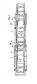
Fig. 1 shows in full a side view of the operational vehicle according to the invention; -
Fig. 2 is a perspective view of the extreme end region of a turntable ladder with telescopically extended hinged arm; -
Fig. 3 is a perspective view of the hinged arm in the extended position; -
Fig. 4 is, correspondingly, a perspective view of the hinged arm in the retracted position; and -
Fig. 5 is a top view of the end region of the turntable ladder corresponding toFig. 2 . - The following description of examples of embodiment apply primarily to the extended hinged arm. For a more exact description of the
basic rescue vehicle 10, theturntable ladder 12 and thehinged arm 14, as well as therescue cage 16, the mentioned utility model 94 16 367 can additionally be referred to. The hingedarm 14 is located in the view shown inFig. 1 in a position which rectilinearly extends the rest of the ladder. Obviously, the hinged arm can also be used in this position. In this elongated position, thehydraulic cylinders 18, which can be extended in order to lower the hinged arm, are shown in the retracted position. Therescue cage 16 has been folded down into the horizontal position in order to reduce the overall length and height. The best conditions for the total length of the vehicle and the driver's view from the driver's cabin (not shown) of therescue vehicle 10 result in the position shown. -
Fig. 2 shows thehydraulic cylinders 18 in the partially extended position. The hingedarm 14 is shown accordingly, lowered about ahorizontal pivot 20 with respect to the rest of the turntable ladder. The hingedarm 14 comprises abase section 22 which has, in the construction customary for turntable ladders, laterallower members 24, bridged byrungs 26, andupper members 28 which form a railing for the safety of rescue personnel. For reasons of stiffening, the upper and lower members are connected by means of cross members in a lattice arrangement. Details are known and do not have to be explained here. - In the construction described, the
base section 22 has an essentially U-shaped cross-section. This applies for the extendedend section 30, which likewise has a U-shaped cross-section withlower members 32, bridged byrungs 34, andupper members 36 which serve as a railing. The U-shaped cross-section of theend section 30 is somewhat smaller than that of thebase section 22, so that theend section 30 can be slid inside thebase section 22, as is customary for turntable ladders of this type. The displacement occurs with the help of a hydraulic cylinder (not shown) integrated in the structure of thebase section 22. As mentioned,Fig. 2 shows the extended position of theend section 30. - One can identify that the
rescue cage 16 is attached to the end of the end section bysupport arms 38,40. Thesupport arms 38,40 are pivot-connected with therescue cage 16 and a hydraulic cylinder (not shown) maintains therescue cage 16 in the vertical position, independent of the position of the whole turntable ladder and of thehinged arm 14. - In order to secure the connection of the hinged
arm 14, or rather theend section 30, to therescue cage 16,lateral support brackets end section 30 and therescue cage 16. Thesesupport brackets end section 30 with the help oftracks 46, so that they can adapt to every inclination of either the ladder orrescue cage 16 respectively. - In
Fig. 2 , moreover, the outline of a drag chain 48 can seen. This drag chain serves to transfer all electrical supply and control cables from the ladder via thebase section 22 to theend section 30. Further connections between theend section 30 and therescue cage 16 are not shown in detail. A telescopically extendable water supply line for the delivery of water for fire-fighting is situated in the connecting area between thebase section 22 and theend section 30. -
Fig. 3 corresponds toFig. 2 and shows the hinged arm in the extended position whileFig. 4 illustrates the retracted position. The reference numbers ofFig. 2 are used for corresponding parts inFig. 3 and 4 , so that an additional, detailed explanation is unnecessary. - The same applies to
Fig. 5. Fig. 5 is a top view of the end region of the ladder and hingedarm 14 in the extended position. A rotary leadthrough 50 for a fire-fightingwater supply line 52 can be identified in the region of thepivot 20 of the hinged arm. In the region shown, the fire-fightingwater supply line 52 consists of anouter pipe 54 and aninner pipe 56, which generate a telescopic connection at the transition from thebase section 22 to theend section 30.
Claims (5)
- Turntable ladder for rescue vehicles with a number of telescopically extendable ladder elements, on the last of which a hinged arm (14), formed as a ladder element, is pivot-mounted about a horizontal pivot (20) characterized in that the hinged arm (14) is telescopically extendable and consists of a base section (22) pivot-mounted to the end of the last ladder element, and, with respect to this, a telescopically displaceable end section (30), each one of said base (22) and end (30) sections has lower members (24,32), bridged by rungs (26,34), and upper members (28, 36), serving as railings, which are connected as a lattice framework and which, as a whole, form a U-shaped cross-section.
- Turntable ladder according to Claim 1, characterised in that the end section (30) can be telescopically slid inside the U-shaped base section (22).
- Turntable ladder according to one of the preceding claims , characterised in that a rescue cage (16) is attached to the end of the end section (30).
- Turntable ladder according to one or more of the preceding claims, characterised in that brackets (42,44), serving as railings, which slide on the upper members (36) of the end section (30), are provided between the rescue cage (16) and end section (30).
- Turntable ladder according to one or more of the preceding claims, characterised in that a telescopically extendable fire-fighting water supply line (52), runs along the hinged arm (14) and forms a connection to a fire-fighting water supply at the extreme end of the end section.
Applications Claiming Priority (1)
| Application Number | Priority Date | Filing Date | Title |
|---|---|---|---|
| DE102005024585.4A DE102005024585B4 (en) | 2005-05-25 | 2005-05-25 | Aerial ladder for rescue vehicles |
Publications (3)
| Publication Number | Publication Date |
|---|---|
| EP1726773A2 EP1726773A2 (en) | 2006-11-29 |
| EP1726773A3 EP1726773A3 (en) | 2007-12-12 |
| EP1726773B1 true EP1726773B1 (en) | 2013-06-19 |
Family
ID=36917301
Family Applications (1)
| Application Number | Title | Priority Date | Filing Date |
|---|---|---|---|
| EP06114454.9A Active EP1726773B1 (en) | 2005-05-25 | 2006-05-24 | Turntable ladder for rescue vehicles |
Country Status (3)
| Country | Link |
|---|---|
| EP (1) | EP1726773B1 (en) |
| DE (1) | DE102005024585B4 (en) |
| ES (1) | ES2426996T3 (en) |
Cited By (5)
| Publication number | Priority date | Publication date | Assignee | Title |
|---|---|---|---|---|
| EP3034455A1 (en) | 2014-12-18 | 2016-06-22 | Iveco Magirus Ag | Method for controlling an aerial apparatus, and aerial apparatus with controller implementing this method |
| EP3754151B1 (en) * | 2019-06-21 | 2022-06-01 | Iveco Magirus Ag | Method for controlling a telescopic lifting device, and telescopic lifting device |
| WO2023164737A1 (en) | 2022-03-03 | 2023-09-07 | Rosenbauer International Ag | Lifting unit comprising a boom arm which is telescopic and comprising a loading device |
| DE102022105086A1 (en) | 2022-03-03 | 2023-09-07 | Rosenbauer International Ag | Extendable ladder set with several ladder sections |
| DE102022109721A1 (en) | 2022-04-22 | 2023-10-26 | Rosenbauer International Ag | Method for forming a supply line for supplying an extinguishing agent to a set of conductors and a set of conductors with a supply line |
Families Citing this family (7)
| Publication number | Priority date | Publication date | Assignee | Title |
|---|---|---|---|---|
| ES2391667T3 (en) | 2008-10-28 | 2012-11-28 | Iveco Magirus Ag | Rescue vehicle ladder set with elevator |
| RU2460862C1 (en) * | 2011-01-20 | 2012-09-10 | Федеральное государственное бюджетное образовательное учреждение высшего профессионального образования "Самарский государственный архитектурно-строительный университет" (СГАСУ) | Method to install sleeve line along building staircase |
| RU2451785C1 (en) * | 2011-01-21 | 2012-05-27 | Федеральное государственное бюджетное образовательное учреждение высшего профессионального образования "Самарский государственный архитектурно-строительный университет" (СГАСУ) | Device to install and fix hose line in building staircases |
| CN102935989B (en) * | 2012-11-15 | 2015-02-11 | 长沙中联消防机械有限公司 | Hydraulic aerial cage and cage guardrail thereof |
| AT513612B1 (en) | 2012-12-21 | 2014-06-15 | Rosenbauer Int Ag | Ladder set, especially fire chief, as well as equipped vehicle |
| AT513614B1 (en) | 2012-12-21 | 2014-06-15 | Rosenbauer Int Ag | Ladder set, especially fire chief, as well as equipped vehicle |
| CN116291173A (en) * | 2023-04-18 | 2023-06-23 | 沈阳捷通消防车有限公司 | A ladder frame structure for the upper arm of a fire truck, a ladder frame mechanism, and a fire truck |
Family Cites Families (11)
| Publication number | Priority date | Publication date | Assignee | Title |
|---|---|---|---|---|
| SE366970B (en) | 1972-09-28 | 1974-05-13 | Braennstroems Mek Brdr | |
| FR2332227A1 (en) | 1975-11-18 | 1977-06-17 | Laing & Son Ltd John | LIFTING GEAR |
| FR2379693A1 (en) * | 1977-02-07 | 1978-09-01 | Camiva | Pivoting extension for telescopic fire rescue ladder - has slidable mounting relative to hinge and is controlled by e.g. hydraulic motors |
| EP0012602A1 (en) | 1978-12-12 | 1980-06-25 | John Laing Services Limited | Access apparatus having a plurality of booms |
| FR2465867A1 (en) * | 1979-09-19 | 1981-03-27 | Camiva | Swivelling Elevated platform for motor vehicle - has platform on hydraulically operated arms folded parallel for transport |
| DE3326673C1 (en) * | 1983-07-23 | 1984-12-20 | Anton Ruthmann Gmbh & Co, 4423 Gescher | Device for controlling the movement of a lifting arm carrying a lifting platform |
| IT1182578B (en) | 1985-09-30 | 1987-10-05 | Fassi Gru Idrauliche Spa | HIGHLY MANEUVERABLE ELECTRICALLY INSULATED CRANE FOR LIFTING AND ACCESSING OPERATORS UNDER VOLTAGE ELECTRIC AERIAL LINES |
| IT222685Z2 (en) | 1991-07-12 | 1995-04-24 | Op Pagliero | STRUCTURE FOR LIFTING AND POSITIONING OF AN AERIAL PLATFORM IN PARTICULAR FOR LIFT MACHINES |
| DE4221673C1 (en) | 1992-07-02 | 1993-06-17 | Anton Ruthmann Gmbh & Co, 4423 Gescher, De | Pivotable lift arm for lift work platform - has at least two telescopic bearers and a platform arm pivotably arranged at end of end bearer |
| US5437345A (en) | 1994-02-16 | 1995-08-01 | Pierce Manufacturing Inc. | Pinnable waterway |
| DE9416367U1 (en) | 1994-10-11 | 1994-12-01 | Iveco Magirus Ag, 89079 Ulm | Aerial ladder for emergency vehicles |
-
2005
- 2005-05-25 DE DE102005024585.4A patent/DE102005024585B4/en not_active Expired - Lifetime
-
2006
- 2006-05-24 ES ES06114454T patent/ES2426996T3/en active Active
- 2006-05-24 EP EP06114454.9A patent/EP1726773B1/en active Active
Cited By (7)
| Publication number | Priority date | Publication date | Assignee | Title |
|---|---|---|---|---|
| EP3034455A1 (en) | 2014-12-18 | 2016-06-22 | Iveco Magirus Ag | Method for controlling an aerial apparatus, and aerial apparatus with controller implementing this method |
| EP3754151B1 (en) * | 2019-06-21 | 2022-06-01 | Iveco Magirus Ag | Method for controlling a telescopic lifting device, and telescopic lifting device |
| WO2023164737A1 (en) | 2022-03-03 | 2023-09-07 | Rosenbauer International Ag | Lifting unit comprising a boom arm which is telescopic and comprising a loading device |
| DE102022105087A1 (en) | 2022-03-03 | 2023-09-07 | Rosenbauer International Ag | Lifting unit with a telescopic extension arm and a clamping device |
| DE102022105086A1 (en) | 2022-03-03 | 2023-09-07 | Rosenbauer International Ag | Extendable ladder set with several ladder sections |
| WO2023164736A1 (en) | 2022-03-03 | 2023-09-07 | Rosenbauer International Ag | Extendable ladder set with a plurality of ladder parts |
| DE102022109721A1 (en) | 2022-04-22 | 2023-10-26 | Rosenbauer International Ag | Method for forming a supply line for supplying an extinguishing agent to a set of conductors and a set of conductors with a supply line |
Also Published As
| Publication number | Publication date |
|---|---|
| ES2426996T3 (en) | 2013-10-28 |
| DE102005024585B4 (en) | 2024-08-08 |
| EP1726773A3 (en) | 2007-12-12 |
| DE102005024585A1 (en) | 2006-11-30 |
| EP1726773A2 (en) | 2006-11-29 |
Similar Documents
| Publication | Publication Date | Title |
|---|---|---|
| EP1726773B1 (en) | Turntable ladder for rescue vehicles | |
| US9447638B2 (en) | Access device | |
| EP3560887B1 (en) | Work platform with extension deck and work step | |
| CN105143588B (en) | Set of ladders, in particular fire ladder and vehicle equipped therewith | |
| DK3247623T3 (en) | SHIP WITH TELESCOPIC GATHROOM FOR TRANSFER OF PERSONS BETWEEN THE SHIP AND AN ESTABLISHED OR NEARLY ESTABLISHED ITEM ON THE SEA, LIKE A WINDMILL | |
| RS64220B1 (en) | ROTARY TELEHANDLER WITH MULTIPLE PATHS FOR ASCENT AND DESCENT | |
| US20240018787A1 (en) | Retractable access means with collapsible handrail assembly | |
| US9222306B2 (en) | Crane access staircase and mounting system | |
| JP3236717U (en) | Mobile crane with folding walking platform | |
| WO2009020331A2 (en) | Movable aerial ladder | |
| AU2013203442B2 (en) | Screen Module | |
| JPH03267297A (en) | Mounting device for jib supporting rod in crane | |
| CN221373588U (en) | Tunnel construction operation platform | |
| JP3329719B2 (en) | Pile driver | |
| RU2001132259A (en) | LIFT DEVICE FOR CAPITAL REPAIR OF WELLS | |
| JP2003192272A (en) | Construction machinery | |
| JPH10140957A (en) | Telescopic ladder | |
| JP2000255459A (en) | Lifting device of construction machine | |
| KR19990019257U (en) | Multi-purpose lift for vehicle mounting | |
| JPS641344Y2 (en) | ||
| KR19980028397A (en) | Safety device for bridge inspection and repair equipment | |
| KR19980028398A (en) | Transportation device for bridge inspection and repair equipment | |
| JPH0460195B2 (en) | ||
| JP2018008818A (en) | Attachment structure of relief angle detector | |
| AU6314999A (en) | Aircraft refuelling apparatus improvement |
Legal Events
| Date | Code | Title | Description |
|---|---|---|---|
| PUAI | Public reference made under article 153(3) epc to a published international application that has entered the european phase |
Free format text: ORIGINAL CODE: 0009012 |
|
| AK | Designated contracting states |
Kind code of ref document: A2 Designated state(s): AT BE BG CH CY CZ DE DK EE ES FI FR GB GR HU IE IS IT LI LT LU LV MC NL PL PT RO SE SI SK TR |
|
| AX | Request for extension of the european patent |
Extension state: AL BA HR MK YU |
|
| PUAL | Search report despatched |
Free format text: ORIGINAL CODE: 0009013 |
|
| AK | Designated contracting states |
Kind code of ref document: A3 Designated state(s): AT BE BG CH CY CZ DE DK EE ES FI FR GB GR HU IE IS IT LI LT LU LV MC NL PL PT RO SE SI SK TR |
|
| AX | Request for extension of the european patent |
Extension state: AL BA HR MK YU |
|
| RIC1 | Information provided on ipc code assigned before grant |
Ipc: E06C 5/04 20060101AFI20060920BHEP |
|
| 17P | Request for examination filed |
Effective date: 20080610 |
|
| AKX | Designation fees paid |
Designated state(s): AT BE BG CH CY CZ DE DK EE ES FI FR GB GR HU IE IS IT LI LT LU LV MC NL PL PT RO SE SI SK TR |
|
| 17Q | First examination report despatched |
Effective date: 20080820 |
|
| GRAP | Despatch of communication of intention to grant a patent |
Free format text: ORIGINAL CODE: EPIDOSNIGR1 |
|
| RIC1 | Information provided on ipc code assigned before grant |
Ipc: E06C 5/04 20060101AFI20121204BHEP Ipc: B66F 11/04 20060101ALI20121204BHEP |
|
| GRAS | Grant fee paid |
Free format text: ORIGINAL CODE: EPIDOSNIGR3 |
|
| GRAA | (expected) grant |
Free format text: ORIGINAL CODE: 0009210 |
|
| AK | Designated contracting states |
Kind code of ref document: B1 Designated state(s): AT BE BG CH CY CZ DE DK EE ES FI FR GB GR HU IE IS IT LI LT LU LV MC NL PL PT RO SE SI SK TR |
|
| REG | Reference to a national code |
Ref country code: GB Ref legal event code: FG4D |
|
| REG | Reference to a national code |
Ref country code: CH Ref legal event code: EP |
|
| REG | Reference to a national code |
Ref country code: AT Ref legal event code: REF Ref document number: 617756 Country of ref document: AT Kind code of ref document: T Effective date: 20130715 |
|
| REG | Reference to a national code |
Ref country code: IE Ref legal event code: FG4D |
|
| REG | Reference to a national code |
Ref country code: DE Ref legal event code: R096 Ref document number: 602006036846 Country of ref document: DE Effective date: 20130814 |
|
| REG | Reference to a national code |
Ref country code: CH Ref legal event code: NV Representative=s name: N&G PATENT SERVICES SA, CH |
|
| REG | Reference to a national code |
Ref country code: SE Ref legal event code: TRGR |
|
| REG | Reference to a national code |
Ref country code: ES Ref legal event code: FG2A Ref document number: 2426996 Country of ref document: ES Kind code of ref document: T3 Effective date: 20131028 |
|
| PG25 | Lapsed in a contracting state [announced via postgrant information from national office to epo] |
Ref country code: GR Free format text: LAPSE BECAUSE OF FAILURE TO SUBMIT A TRANSLATION OF THE DESCRIPTION OR TO PAY THE FEE WITHIN THE PRESCRIBED TIME-LIMIT Effective date: 20130920 Ref country code: LT Free format text: LAPSE BECAUSE OF FAILURE TO SUBMIT A TRANSLATION OF THE DESCRIPTION OR TO PAY THE FEE WITHIN THE PRESCRIBED TIME-LIMIT Effective date: 20130619 Ref country code: SI Free format text: LAPSE BECAUSE OF FAILURE TO SUBMIT A TRANSLATION OF THE DESCRIPTION OR TO PAY THE FEE WITHIN THE PRESCRIBED TIME-LIMIT Effective date: 20130619 Ref country code: FI Free format text: LAPSE BECAUSE OF FAILURE TO SUBMIT A TRANSLATION OF THE DESCRIPTION OR TO PAY THE FEE WITHIN THE PRESCRIBED TIME-LIMIT Effective date: 20130619 |
|
| REG | Reference to a national code |
Ref country code: LT Ref legal event code: MG4D |
|
| PG25 | Lapsed in a contracting state [announced via postgrant information from national office to epo] |
Ref country code: BG Free format text: LAPSE BECAUSE OF FAILURE TO SUBMIT A TRANSLATION OF THE DESCRIPTION OR TO PAY THE FEE WITHIN THE PRESCRIBED TIME-LIMIT Effective date: 20130919 |
|
| REG | Reference to a national code |
Ref country code: NL Ref legal event code: VDEP Effective date: 20130619 |
|
| PG25 | Lapsed in a contracting state [announced via postgrant information from national office to epo] |
Ref country code: LV Free format text: LAPSE BECAUSE OF FAILURE TO SUBMIT A TRANSLATION OF THE DESCRIPTION OR TO PAY THE FEE WITHIN THE PRESCRIBED TIME-LIMIT Effective date: 20130619 |
|
| PG25 | Lapsed in a contracting state [announced via postgrant information from national office to epo] |
Ref country code: CZ Free format text: LAPSE BECAUSE OF FAILURE TO SUBMIT A TRANSLATION OF THE DESCRIPTION OR TO PAY THE FEE WITHIN THE PRESCRIBED TIME-LIMIT Effective date: 20130619 Ref country code: IS Free format text: LAPSE BECAUSE OF FAILURE TO SUBMIT A TRANSLATION OF THE DESCRIPTION OR TO PAY THE FEE WITHIN THE PRESCRIBED TIME-LIMIT Effective date: 20131019 Ref country code: EE Free format text: LAPSE BECAUSE OF FAILURE TO SUBMIT A TRANSLATION OF THE DESCRIPTION OR TO PAY THE FEE WITHIN THE PRESCRIBED TIME-LIMIT Effective date: 20130619 Ref country code: PT Free format text: LAPSE BECAUSE OF FAILURE TO SUBMIT A TRANSLATION OF THE DESCRIPTION OR TO PAY THE FEE WITHIN THE PRESCRIBED TIME-LIMIT Effective date: 20131021 Ref country code: SK Free format text: LAPSE BECAUSE OF FAILURE TO SUBMIT A TRANSLATION OF THE DESCRIPTION OR TO PAY THE FEE WITHIN THE PRESCRIBED TIME-LIMIT Effective date: 20130619 Ref country code: CY Free format text: LAPSE BECAUSE OF FAILURE TO SUBMIT A TRANSLATION OF THE DESCRIPTION OR TO PAY THE FEE WITHIN THE PRESCRIBED TIME-LIMIT Effective date: 20130710 Ref country code: BE Free format text: LAPSE BECAUSE OF FAILURE TO SUBMIT A TRANSLATION OF THE DESCRIPTION OR TO PAY THE FEE WITHIN THE PRESCRIBED TIME-LIMIT Effective date: 20130619 |
|
| PG25 | Lapsed in a contracting state [announced via postgrant information from national office to epo] |
Ref country code: RO Free format text: LAPSE BECAUSE OF FAILURE TO SUBMIT A TRANSLATION OF THE DESCRIPTION OR TO PAY THE FEE WITHIN THE PRESCRIBED TIME-LIMIT Effective date: 20130619 Ref country code: PL Free format text: LAPSE BECAUSE OF FAILURE TO SUBMIT A TRANSLATION OF THE DESCRIPTION OR TO PAY THE FEE WITHIN THE PRESCRIBED TIME-LIMIT Effective date: 20130619 Ref country code: NL Free format text: LAPSE BECAUSE OF FAILURE TO SUBMIT A TRANSLATION OF THE DESCRIPTION OR TO PAY THE FEE WITHIN THE PRESCRIBED TIME-LIMIT Effective date: 20130619 |
|
| PG25 | Lapsed in a contracting state [announced via postgrant information from national office to epo] |
Ref country code: CY Free format text: LAPSE BECAUSE OF FAILURE TO SUBMIT A TRANSLATION OF THE DESCRIPTION OR TO PAY THE FEE WITHIN THE PRESCRIBED TIME-LIMIT Effective date: 20130619 |
|
| PLBE | No opposition filed within time limit |
Free format text: ORIGINAL CODE: 0009261 |
|
| STAA | Information on the status of an ep patent application or granted ep patent |
Free format text: STATUS: NO OPPOSITION FILED WITHIN TIME LIMIT |
|
| PG25 | Lapsed in a contracting state [announced via postgrant information from national office to epo] |
Ref country code: DK Free format text: LAPSE BECAUSE OF FAILURE TO SUBMIT A TRANSLATION OF THE DESCRIPTION OR TO PAY THE FEE WITHIN THE PRESCRIBED TIME-LIMIT Effective date: 20130619 |
|
| 26N | No opposition filed |
Effective date: 20140320 |
|
| REG | Reference to a national code |
Ref country code: DE Ref legal event code: R097 Ref document number: 602006036846 Country of ref document: DE Effective date: 20140320 |
|
| PG25 | Lapsed in a contracting state [announced via postgrant information from national office to epo] |
Ref country code: LU Free format text: LAPSE BECAUSE OF FAILURE TO SUBMIT A TRANSLATION OF THE DESCRIPTION OR TO PAY THE FEE WITHIN THE PRESCRIBED TIME-LIMIT Effective date: 20140524 |
|
| PG25 | Lapsed in a contracting state [announced via postgrant information from national office to epo] |
Ref country code: MC Free format text: LAPSE BECAUSE OF FAILURE TO SUBMIT A TRANSLATION OF THE DESCRIPTION OR TO PAY THE FEE WITHIN THE PRESCRIBED TIME-LIMIT Effective date: 20130619 |
|
| REG | Reference to a national code |
Ref country code: IE Ref legal event code: MM4A |
|
| PG25 | Lapsed in a contracting state [announced via postgrant information from national office to epo] |
Ref country code: IE Free format text: LAPSE BECAUSE OF NON-PAYMENT OF DUE FEES Effective date: 20140524 |
|
| REG | Reference to a national code |
Ref country code: FR Ref legal event code: PLFP Year of fee payment: 10 |
|
| REG | Reference to a national code |
Ref country code: FR Ref legal event code: PLFP Year of fee payment: 11 |
|
| PG25 | Lapsed in a contracting state [announced via postgrant information from national office to epo] |
Ref country code: TR Free format text: LAPSE BECAUSE OF FAILURE TO SUBMIT A TRANSLATION OF THE DESCRIPTION OR TO PAY THE FEE WITHIN THE PRESCRIBED TIME-LIMIT Effective date: 20130619 Ref country code: HU Free format text: LAPSE BECAUSE OF FAILURE TO SUBMIT A TRANSLATION OF THE DESCRIPTION OR TO PAY THE FEE WITHIN THE PRESCRIBED TIME-LIMIT; INVALID AB INITIO Effective date: 20060524 |
|
| REG | Reference to a national code |
Ref country code: FR Ref legal event code: PLFP Year of fee payment: 12 |
|
| REG | Reference to a national code |
Ref country code: FR Ref legal event code: PLFP Year of fee payment: 13 |
|
| P01 | Opt-out of the competence of the unified patent court (upc) registered |
Effective date: 20230522 |
|
| PGFP | Annual fee paid to national office [announced via postgrant information from national office to epo] |
Ref country code: CH Payment date: 20230602 Year of fee payment: 18 |
|
| REG | Reference to a national code |
Ref country code: CH Ref legal event code: PL |
|
| PG25 | Lapsed in a contracting state [announced via postgrant information from national office to epo] |
Ref country code: CH Free format text: LAPSE BECAUSE OF NON-PAYMENT OF DUE FEES Effective date: 20240531 |
|
| PGFP | Annual fee paid to national office [announced via postgrant information from national office to epo] |
Ref country code: DE Payment date: 20250528 Year of fee payment: 20 |
|
| PGFP | Annual fee paid to national office [announced via postgrant information from national office to epo] |
Ref country code: GB Payment date: 20250520 Year of fee payment: 20 Ref country code: ES Payment date: 20250612 Year of fee payment: 20 |
|
| PGFP | Annual fee paid to national office [announced via postgrant information from national office to epo] |
Ref country code: IT Payment date: 20250512 Year of fee payment: 20 |
|
| PGFP | Annual fee paid to national office [announced via postgrant information from national office to epo] |
Ref country code: FR Payment date: 20250526 Year of fee payment: 20 |
|
| PGFP | Annual fee paid to national office [announced via postgrant information from national office to epo] |
Ref country code: AT Payment date: 20250520 Year of fee payment: 20 |
|
| PGFP | Annual fee paid to national office [announced via postgrant information from national office to epo] |
Ref country code: SE Payment date: 20250526 Year of fee payment: 20 |