EP1726876A1 - Improved method of combusting solid waste - Google Patents
Improved method of combusting solid waste Download PDFInfo
- Publication number
- EP1726876A1 EP1726876A1 EP05253289A EP05253289A EP1726876A1 EP 1726876 A1 EP1726876 A1 EP 1726876A1 EP 05253289 A EP05253289 A EP 05253289A EP 05253289 A EP05253289 A EP 05253289A EP 1726876 A1 EP1726876 A1 EP 1726876A1
- Authority
- EP
- European Patent Office
- Prior art keywords
- waste
- combustion
- stoker
- air
- gas
- Prior art date
- Legal status (The legal status is an assumption and is not a legal conclusion. Google has not performed a legal analysis and makes no representation as to the accuracy of the status listed.)
- Granted
Links
- 238000000034 method Methods 0.000 title claims abstract description 23
- 239000002910 solid waste Substances 0.000 title description 2
- 238000002485 combustion reaction Methods 0.000 claims abstract description 262
- 239000002699 waste material Substances 0.000 claims abstract description 200
- 239000000567 combustion gas Substances 0.000 claims abstract description 114
- 238000011144 upstream manufacturing Methods 0.000 claims abstract description 17
- 230000002159 abnormal effect Effects 0.000 claims abstract description 10
- 239000007789 gas Substances 0.000 claims description 44
- QVGXLLKOCUKJST-UHFFFAOYSA-N atomic oxygen Chemical compound [O] QVGXLLKOCUKJST-UHFFFAOYSA-N 0.000 claims description 24
- 229910052760 oxygen Inorganic materials 0.000 claims description 24
- 239000001301 oxygen Substances 0.000 claims description 24
- 238000009826 distribution Methods 0.000 claims description 19
- 238000001035 drying Methods 0.000 claims description 16
- 239000000203 mixture Substances 0.000 claims description 8
- 238000002156 mixing Methods 0.000 claims description 6
- 238000003756 stirring Methods 0.000 claims description 6
- 230000005484 gravity Effects 0.000 claims description 5
- 230000005855 radiation Effects 0.000 claims description 5
- 230000000717 retained effect Effects 0.000 claims 2
- 238000009827 uniform distribution Methods 0.000 claims 1
- 238000011084 recovery Methods 0.000 abstract description 6
- 238000007599 discharging Methods 0.000 abstract description 4
- 231100000331 toxic Toxicity 0.000 abstract description 2
- 230000002588 toxic effect Effects 0.000 abstract description 2
- 229910002090 carbon oxide Inorganic materials 0.000 description 16
- 238000007664 blowing Methods 0.000 description 12
- 239000002956 ash Substances 0.000 description 9
- 238000010586 diagram Methods 0.000 description 7
- 150000002013 dioxins Chemical class 0.000 description 6
- 239000002918 waste heat Substances 0.000 description 5
- 231100000614 poison Toxicity 0.000 description 4
- 238000000746 purification Methods 0.000 description 4
- 239000003440 toxic substance Substances 0.000 description 4
- 235000002918 Fraxinus excelsior Nutrition 0.000 description 3
- VEXZGXHMUGYJMC-UHFFFAOYSA-N Hydrochloric acid Chemical compound Cl VEXZGXHMUGYJMC-UHFFFAOYSA-N 0.000 description 3
- 230000007797 corrosion Effects 0.000 description 2
- 238000005260 corrosion Methods 0.000 description 2
- 239000000428 dust Substances 0.000 description 2
- 239000010813 municipal solid waste Substances 0.000 description 2
- 229920003023 plastic Polymers 0.000 description 2
- 239000004033 plastic Substances 0.000 description 2
- 239000004215 Carbon black (E152) Substances 0.000 description 1
- UGFAIRIUMAVXCW-UHFFFAOYSA-N Carbon monoxide Chemical class [O+]#[C-] UGFAIRIUMAVXCW-UHFFFAOYSA-N 0.000 description 1
- 230000005856 abnormality Effects 0.000 description 1
- 238000009841 combustion method Methods 0.000 description 1
- 238000007796 conventional method Methods 0.000 description 1
- 230000000694 effects Effects 0.000 description 1
- 230000002708 enhancing effect Effects 0.000 description 1
- 238000002309 gasification Methods 0.000 description 1
- 229930195733 hydrocarbon Natural products 0.000 description 1
- 150000002430 hydrocarbons Chemical class 0.000 description 1
- 239000002440 industrial waste Substances 0.000 description 1
- 230000002401 inhibitory effect Effects 0.000 description 1
- 230000014759 maintenance of location Effects 0.000 description 1
- 238000005259 measurement Methods 0.000 description 1
- 229920000915 polyvinyl chloride Polymers 0.000 description 1
- 239000004800 polyvinyl chloride Substances 0.000 description 1
- 239000002243 precursor Substances 0.000 description 1
- 238000006722 reduction reaction Methods 0.000 description 1
- 238000004056 waste incineration Methods 0.000 description 1
Images

Classifications
-
- F—MECHANICAL ENGINEERING; LIGHTING; HEATING; WEAPONS; BLASTING
- F23—COMBUSTION APPARATUS; COMBUSTION PROCESSES
- F23G—CREMATION FURNACES; CONSUMING WASTE PRODUCTS BY COMBUSTION
- F23G5/00—Incineration of waste; Incinerator constructions; Details, accessories or control therefor
- F23G5/02—Incineration of waste; Incinerator constructions; Details, accessories or control therefor with pretreatment
- F23G5/04—Incineration of waste; Incinerator constructions; Details, accessories or control therefor with pretreatment drying
- F23G5/05—Incineration of waste; Incinerator constructions; Details, accessories or control therefor with pretreatment drying using drying grates
-
- F—MECHANICAL ENGINEERING; LIGHTING; HEATING; WEAPONS; BLASTING
- F23—COMBUSTION APPARATUS; COMBUSTION PROCESSES
- F23G—CREMATION FURNACES; CONSUMING WASTE PRODUCTS BY COMBUSTION
- F23G5/00—Incineration of waste; Incinerator constructions; Details, accessories or control therefor
- F23G5/08—Incineration of waste; Incinerator constructions; Details, accessories or control therefor having supplementary heating
- F23G5/14—Incineration of waste; Incinerator constructions; Details, accessories or control therefor having supplementary heating including secondary combustion
- F23G5/16—Incineration of waste; Incinerator constructions; Details, accessories or control therefor having supplementary heating including secondary combustion in a separate combustion chamber
- F23G5/165—Incineration of waste; Incinerator constructions; Details, accessories or control therefor having supplementary heating including secondary combustion in a separate combustion chamber arranged at a different level
-
- F—MECHANICAL ENGINEERING; LIGHTING; HEATING; WEAPONS; BLASTING
- F23—COMBUSTION APPARATUS; COMBUSTION PROCESSES
- F23G—CREMATION FURNACES; CONSUMING WASTE PRODUCTS BY COMBUSTION
- F23G5/00—Incineration of waste; Incinerator constructions; Details, accessories or control therefor
- F23G5/50—Control or safety arrangements
-
- F—MECHANICAL ENGINEERING; LIGHTING; HEATING; WEAPONS; BLASTING
- F23—COMBUSTION APPARATUS; COMBUSTION PROCESSES
- F23L—SUPPLYING AIR OR NON-COMBUSTIBLE LIQUIDS OR GASES TO COMBUSTION APPARATUS IN GENERAL ; VALVES OR DAMPERS SPECIALLY ADAPTED FOR CONTROLLING AIR SUPPLY OR DRAUGHT IN COMBUSTION APPARATUS; INDUCING DRAUGHT IN COMBUSTION APPARATUS; TOPS FOR CHIMNEYS OR VENTILATING SHAFTS; TERMINALS FOR FLUES
- F23L1/00—Passages or apertures for delivering primary air for combustion
- F23L1/02—Passages or apertures for delivering primary air for combustion by discharging the air below the fire
-
- F—MECHANICAL ENGINEERING; LIGHTING; HEATING; WEAPONS; BLASTING
- F23—COMBUSTION APPARATUS; COMBUSTION PROCESSES
- F23L—SUPPLYING AIR OR NON-COMBUSTIBLE LIQUIDS OR GASES TO COMBUSTION APPARATUS IN GENERAL ; VALVES OR DAMPERS SPECIALLY ADAPTED FOR CONTROLLING AIR SUPPLY OR DRAUGHT IN COMBUSTION APPARATUS; INDUCING DRAUGHT IN COMBUSTION APPARATUS; TOPS FOR CHIMNEYS OR VENTILATING SHAFTS; TERMINALS FOR FLUES
- F23L9/00—Passages or apertures for delivering secondary air for completing combustion of fuel
- F23L9/02—Passages or apertures for delivering secondary air for completing combustion of fuel by discharging the air above the fire
-
- F—MECHANICAL ENGINEERING; LIGHTING; HEATING; WEAPONS; BLASTING
- F23—COMBUSTION APPARATUS; COMBUSTION PROCESSES
- F23N—REGULATING OR CONTROLLING COMBUSTION
- F23N3/00—Regulating air supply or draught
-
- F—MECHANICAL ENGINEERING; LIGHTING; HEATING; WEAPONS; BLASTING
- F23—COMBUSTION APPARATUS; COMBUSTION PROCESSES
- F23G—CREMATION FURNACES; CONSUMING WASTE PRODUCTS BY COMBUSTION
- F23G2202/00—Combustion
- F23G2202/10—Combustion in two or more stages
- F23G2202/101—Combustion in two or more stages with controlled oxidant supply
-
- F—MECHANICAL ENGINEERING; LIGHTING; HEATING; WEAPONS; BLASTING
- F23—COMBUSTION APPARATUS; COMBUSTION PROCESSES
- F23G—CREMATION FURNACES; CONSUMING WASTE PRODUCTS BY COMBUSTION
- F23G2202/00—Combustion
- F23G2202/10—Combustion in two or more stages
- F23G2202/103—Combustion in two or more stages in separate chambers
-
- F—MECHANICAL ENGINEERING; LIGHTING; HEATING; WEAPONS; BLASTING
- F23—COMBUSTION APPARATUS; COMBUSTION PROCESSES
- F23G—CREMATION FURNACES; CONSUMING WASTE PRODUCTS BY COMBUSTION
- F23G2203/00—Furnace arrangements
- F23G2203/10—Stoker grate furnace
-
- F—MECHANICAL ENGINEERING; LIGHTING; HEATING; WEAPONS; BLASTING
- F23—COMBUSTION APPARATUS; COMBUSTION PROCESSES
- F23G—CREMATION FURNACES; CONSUMING WASTE PRODUCTS BY COMBUSTION
- F23G2206/00—Waste heat recuperation
- F23G2206/10—Waste heat recuperation reintroducing the heat in the same process, e.g. for predrying
-
- F—MECHANICAL ENGINEERING; LIGHTING; HEATING; WEAPONS; BLASTING
- F23—COMBUSTION APPARATUS; COMBUSTION PROCESSES
- F23G—CREMATION FURNACES; CONSUMING WASTE PRODUCTS BY COMBUSTION
- F23G2207/00—Control
- F23G2207/10—Arrangement of sensing devices
- F23G2207/101—Arrangement of sensing devices for temperature
-
- F—MECHANICAL ENGINEERING; LIGHTING; HEATING; WEAPONS; BLASTING
- F23—COMBUSTION APPARATUS; COMBUSTION PROCESSES
- F23G—CREMATION FURNACES; CONSUMING WASTE PRODUCTS BY COMBUSTION
- F23G2207/00—Control
- F23G2207/10—Arrangement of sensing devices
- F23G2207/103—Arrangement of sensing devices for oxygen
-
- F—MECHANICAL ENGINEERING; LIGHTING; HEATING; WEAPONS; BLASTING
- F23—COMBUSTION APPARATUS; COMBUSTION PROCESSES
- F23G—CREMATION FURNACES; CONSUMING WASTE PRODUCTS BY COMBUSTION
- F23G2207/00—Control
- F23G2207/10—Arrangement of sensing devices
- F23G2207/104—Arrangement of sensing devices for CO or CO2
-
- F—MECHANICAL ENGINEERING; LIGHTING; HEATING; WEAPONS; BLASTING
- F23—COMBUSTION APPARATUS; COMBUSTION PROCESSES
- F23G—CREMATION FURNACES; CONSUMING WASTE PRODUCTS BY COMBUSTION
- F23G2207/00—Control
- F23G2207/10—Arrangement of sensing devices
- F23G2207/105—Arrangement of sensing devices for NOx
-
- F—MECHANICAL ENGINEERING; LIGHTING; HEATING; WEAPONS; BLASTING
- F23—COMBUSTION APPARATUS; COMBUSTION PROCESSES
- F23G—CREMATION FURNACES; CONSUMING WASTE PRODUCTS BY COMBUSTION
- F23G2207/00—Control
- F23G2207/10—Arrangement of sensing devices
- F23G2207/112—Arrangement of sensing devices for waste supply flowrate
-
- F—MECHANICAL ENGINEERING; LIGHTING; HEATING; WEAPONS; BLASTING
- F23—COMBUSTION APPARATUS; COMBUSTION PROCESSES
- F23G—CREMATION FURNACES; CONSUMING WASTE PRODUCTS BY COMBUSTION
- F23G2207/00—Control
- F23G2207/10—Arrangement of sensing devices
- F23G2207/113—Arrangement of sensing devices for oxidant supply flowrate
-
- F—MECHANICAL ENGINEERING; LIGHTING; HEATING; WEAPONS; BLASTING
- F23—COMBUSTION APPARATUS; COMBUSTION PROCESSES
- F23G—CREMATION FURNACES; CONSUMING WASTE PRODUCTS BY COMBUSTION
- F23G2207/00—Control
- F23G2207/10—Arrangement of sensing devices
- F23G2207/114—Arrangement of sensing devices for combustion bed level
-
- F—MECHANICAL ENGINEERING; LIGHTING; HEATING; WEAPONS; BLASTING
- F23—COMBUSTION APPARATUS; COMBUSTION PROCESSES
- F23G—CREMATION FURNACES; CONSUMING WASTE PRODUCTS BY COMBUSTION
- F23G2207/00—Control
- F23G2207/30—Oxidant supply
-
- F—MECHANICAL ENGINEERING; LIGHTING; HEATING; WEAPONS; BLASTING
- F23—COMBUSTION APPARATUS; COMBUSTION PROCESSES
- F23N—REGULATING OR CONTROLLING COMBUSTION
- F23N2229/00—Flame sensors
- F23N2229/20—Camera viewing
Definitions
- the present invention relates to improvements to a method of combusting municipal solid waste such as industrial waste, household solid waste and the like (hereinafter called waste) with a stoker-type waste incinerator.
- waste Municipal solid waste
- the present invention concerns improvements in such a method of combusting waste by using a stoker-type waste incinerator at a low air ratio. This enables the stoker-type waste incinerator to combust waste efficiently and perfectly whilst using a reduced amount of fed combustion air, to substantially reduce generation of toxic substances, to improve heat recovery efficiency, and to downsize the dimensions of both the stoker-type waste incinerator and exhaust gas treatment facilities.
- Waste incinerators commonly used include either stoker-type waste incinerators or fluidized bed-type waste incinerators, with the stoker-type waste incinerator being the most popular type.
- FIG. 5 illustrates one example of a stoker-type waste incinerator.
- Said stoker-type waste incinerator 50 comprises a furnace 51, a waste hopper 52, a feeder pusher 53, a stoker 54, an under-stoker hopper 55, a primary combustion chamber 56, a secondary combustion chamber 57, a primary combustion air duct 58, a secondary combustion air duct 59, an ash discharge chute 60, an exhaust gas outlet 61 and the like.
- the stoker 54 consists of a drying stoker 54a, a combustion stoker 54b and a burnout stoker 54c, to feed the primary combustion air A1 from underneath the stoker 54 to stokers 54a, 54b and 54c.
- the waste W fed into the waste hopper 52 is fed onto the drying stoker 54a in succession with a feeder pusher 53, and then heated and dried with primary combustion air A1 fed from underneath the drying stoker 54a and also with radiant heat from the upper-positioned primary combustion chamber 56 at elevated temperatures.
- primary combustion air A1 fed from underneath the drying stoker 54a and also with radiant heat from the upper-positioned primary combustion chamber 56 at elevated temperatures.
- Dried waste W is conveyed from the drying stoker 54a to the combustion stoker 54b, and burned in flames with primary combustion air A1b fed from its underneath thereon. It reaches the burnout position just at the end part on the downstream side of the combustion stoker 54b. Then, the waste W burned out in proximity to the end part of the downstream side of the combustion stoker 54b is conveyed onto the burnout stoker 54c. Next, after so-called embers are burnt with primary combustion air Alc fed from underneath the burnout stoker 54c, the incineration residues (having typically unburned combustibles content of 5% or less) are discharged from the ash discharge chute 60 downward.
- primary combustion gas G containing the unburned gas and unburned combustibles, which were generated while drying and burning the waste W, flows into the second combustion chamber 57 that is installed above the primary combustion chamber 50. It is, then, discharged from the exhaust gas outlet 61 to the outside after so-called secondary combustion has been performed in the secondary combustion chamber 57 by feeding the secondary combustion air A2, to achieve complete combustion.
- compositions and temperatures of the combustion gas generated while waste W is combusted differ depending on where it is combusted.
- a zone is formed where the combustion gas containing a large quantity of the unburned gas such as CO and the like is generated, a further zone is formed where the combustion gas containing a large quantity of NOx is generated with intensive burning, and a yet a further zone is formed where the low temperature combustion gas of 500 ⁇ 700° C containing the residual oxygen of more than 15% with the excess air, thus making the combustion gas inside the primary combustion chamber 56 to be in such a state that the distribution of compositions and temperatures is found not to be uniform.
- This is to be obtained in a manner that combustion gas with high oxygen concentration can be drawn from the range where the burnout stoker in the primary combustion chamber of the stoker-type waste incinerator, and the combustion gas drawn is fed to the primary combustion gas underneath the feeding position of the secondary combustion air, that is, on the upstream side.
- a mixing, stirring and reduction zone of the primary combustion gas is formed.
- a steady state control part mainly responsible at least for the combustion control in normal operating conditions including the control of heat inputs of the waste fed, the control of the combustion-center and burnout position and the real time control of the secondary combustion air and a fuzzy control part responsible for restoring the abnormal combustion to the steady state of combustion when the abnormal combustion of waste happens can be employed.
- the present invention in one aspect provides a method of combusting waste according to claim 1.
- Figure 1 is a whole block diagram of a stoker-type waste incinerator employed in one embodiment of the present invention
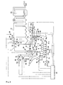
- FIG. 1 illustrates an example of a stoker-type waste incinerator 1 for carrying out the method according to the present invention.
- Said stoker-type waste incinerator 1 comprises a furnace body 2 formed with a furnace wall, a waste hopper 3 in which waste W is fed, a stoker 4 for burning waste W, a waste feeder 5 to feed waste W onto the stoker 4, an under-stoker hopper 6 installed underneath the stoker 4, a combustion chamber (reference number omitted) consisting of a primary combustion chamber 7 formed above the stoker 4 and a secondary combustion chamber 8 formed above the primary combustion chamber 7, an ash discharge chute 9 for discharging incineration ashes.
- a exhaust gas outlet 10 is present for discharging the secondary combustion gas Go, a primary combustion air blower 11 feeds the primary combustion air A1 into the primary combustion chamber 7 from beneath the stoker 4, a duct of re-circulating combustion gas 12 leads the re-circulating combustion gas G', drawn from the primary combustion chamber 7 on the downstream side of the stoker 4, to the outside of the primary combustion chamber 7, into the combustion chamber on the upstream side of the blow-in position of the secondary combustion air A2.
- a fan 13 is located within the duct of re-circulating combustion gas 12, a heat exchanger 14 is provided in the duct of re-circulating combustion gas 12 on the upstream side of the fan 13.
- An air duct 15 is connected to the heat exchanger and the like to take out fresh air A preheated by the heat exchanger, a secondary combustion air blower 16, a stoker driving device 17 to actuate the stoker 4, and dampers 18, 19a ⁇ 19g.
- 5a designates a driving part of the waste feeder(waste feeder controller), 11a a driving part of the primary combustion air blower(primary combustion air blower controller), 13a a driving part of the fan, 16a a driving part of the secondary combustion air blower(secondary combustion air blower controller), 17a a stoker driving device controller, and 18a.20 damper controllers.
- 21 designates a waste heat recovery boiler, 22 a boiler drum, 23 an exhaust gas treatment equipment, and 24a an automatic combustion control unit.
- 25 designates a waste scale
- 26 a scanning laser-type level meter
- 28 a waste layer thickness meter
- 29 a gas thermometer
- 30 a scanning-type infrared radiation thermometer
- 31 a NOx analyzer
- 32 an 02 analyzer
- 33 a CO analyzer
- 34 a steam pressure gauge and thermometer and 35 a steam flow meter.
- the above-mentioned stoker 4 comprises a drying stoker 4a, a combustion stoker 4b and a burnout stoker 4c, and an under-stoker hopper 6 is located underneath the stokers 4a, 4b and 4c respectively.
- These stoker 4a, 4b and 4c are formed with both conventionally known travelling grates (not illustrated), and fixed grates (not illustrated), which are arranged in alternating order.
- the waste W on the stoker 4 is moved forward from the upstream side to the downstream side while stirring it in a reciprocating motion of travelling grates back and forth with a certain pitch by the stoker driving device 17.
- a primary combustion chamber 7 for drying and combusting the waste W while it moves forward on the stoker 4 with primary combustion air A1a ⁇ A1c fed from underneath the stoker 4.
- a secondary combustion chamber 8 for combusting the unburned gas such as CO and the like and unburned combustibles generated in the primary combustion chamber with secondary combustion air A2.
- the above-mentioned primary combustion air blower 11 which is for supplying the primary combustion air A1 to the lower part of the stokers 4a, 4b and 4c through the under-stoker hoppers 6 under the stoker 4, is equipped with a plural number of air volume adjusting dampers 19a ⁇ 19g. Further, damper controllers 20 control the opening/closing of these dampers 19a ⁇ 19g with which the amount of the primary combustion air A1 fed to the lower part of the stoker 4a, 4b and 4c is adjusted.
- the amount of the primary combustion air A1 fed from underneath the stoker 4 is controlled, typically the primary air ratio (the amount of the primary combustion air/the amount of the theoretical combustion air) being 0.8 ⁇ 1.0.
- the primary air ratio the amount of the primary combustion air/the amount of the theoretical combustion air
- usually approximately 70 ⁇ 80% of the primary combustion air A1 is fed from the combustion stoker 4b, to form the reduction zone containing the unburned gas, such as CO, HC and the like above the combustion stoker 4b, so that the space above the combustion stoker 4b is made to be the atmosphere inhibiting to the generation of NOx.
- approximately 20% of the primary combustion air A1c is fed from the burnout stoker 4c, to achieve complete combustion of the unburned combustibles in the ashes.
- the distribution amount and temperature of the primary combustion air A1a ⁇ A1c fed to the lower part of stokers 4a, 4b and 4c and the amount of waste forwarded by the stokers are controlled so that the residual oxygen in the re-circulating combustion gas G' is typically found to be more than 15%, and the temperatures above the burnout stoker 4c to be a value set generally between 600 ⁇ 800°C.
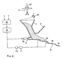
- the above-mentioned duct of re-circulating combustion gas 12 is for leading the re-circulating combustion gas G' on the upper part on the downstream side of the stoker 4 (the upper part of the burnout stoker 4c) being drawn to the outside of the primary combustion chamber 7 into the combustion chamber on the upstream side of the blow position of the secondary combustion air A2.
- the re-circulating combustion gas G' above the burnout stoker 4c is drawn to the outside of the furnace, and the drawn re-circulating combustion gas G' is blown into the combustion chamber on the upstream side of the blow-in position of the secondary combustion air A2 to mix and stir the primary combustion gas G generated inside the primary combustion chamber 7.
- a slightly reducing atmosphere (reduction zone B) where the composition and temperatures of the primary combustion gas G become uniform is formed at a region of the combustion chamber upstream of the blow-in position of the secondary combustion air A2 to prevent the generation of NOx, and to combust unburned gas and the like completely by supplying the minimum amount of secondary combustion air A2 thereafter.
- the retention time of the afore-mentioned primary combustion gas G is such that at the reduction zone B (i.e. the time required to pass the reduction zone B) is typically 0.5 seconds or longer, and generally it can retain in the high temperature zone of higher than 850°C for 1.5 seconds or longer after supplying secondary combustion air.
- the above-mentioned heat exchanger 14 is provided in the duct of re-circulating combustion gas 12 on the upstream side of the fan 13 (with this example, inside the suction chamber 12a) to reduce the temperature of the re-circulating combustion gas G'.
- An economizer, deaeration heater, boiler, air heater and the like can typically be employed as such a heat exchanger 14.
- Corrosive gases such as HCl, SOx and the like, in the afore-mentioned primary combustion gas, are generated when plastics such as polyvinyl chloride and the like, contained in waste W, are combusted. Plastics are mainly burned on the combustion stoker 4b because they are decomposed and are generally burned at temperatures of 350°C ⁇ 500°C at a relatively high velocity of combustion.
- corrosive gases are mainly generated on the combustion stoker 4b, and found in the primary combustion gas G above the combustion stoker 4b and drying stoker 4a, while the re-circulating combustion gas G' above the burnout stoker 4c has a lesser concentration of corrosive gas and dust, thus allowing the afore-mentioned heat exchanger 14 to be provided inside the suction chamber 12a so as to draw the re-circulating combustion gas G' above the burnout stoker 4c. And, there are caused no problems such as corrosion and the like even when the re-circulating combustion gas G' which temperatures are reduced to 200°C ⁇ 300°C is blown into the secondary combustion chamber 8 by the fan 13.
- the afore-mentioned secondary combustion air blower 16 is for supplying the secondary combustion air A2 to the blowing nozzles of secondary combustion air16b formed on the furnace wall of the secondary combustion chamber 8.
- the volume of the secondary combustion air A2 blown into the secondary combustion chamber 8 is adjusted by means of a damper 18.
- the volume of the secondary combustion air A2 fed into the secondary combustion chamber 8 is set at 0.3 ⁇ 0.4 as its secondary air ratio (the secondary combustion air volume/the theoretical combustion air volume), and the total volume of the primary combustion air A1 and secondary combustion air A2 is set at 1.3 as its air ratio.
- the oxygen concentration of the secondary combustion gas Go is continuously measured at real time by the laser-type oxygen analyzer 32 and the volume of the secondary combustion air is controlled to make the oxygen concentration to be approximately 5% (dry).
- FIG. 2 is a schematic system diagram that illustrates a heat input measuring device and a waste feeding controller for which a below mentioned waste scale 25 and a scanning laser-type level meter 26 are employed.
- the waste scale 25 can be used for measuring the weight of waste picked up by a crane C, and the measured data are inputted to the waste quality and heat input computation part 36.
- the data on the waste volume in the waste hopper 3 obtained by the scanning laser-type level meter 26 installed above the waste hopper 3 is also inputted to the waste quality and heat input computation part 36.
- the waste quality (heat value) is estimated based on the specific gravity of the waste computed by both afore-mentioned inputted volume and weight of the waste and stored each time the waste is fed. Also, changes in the total volume of the waste per unit time are computed from the total volume of the waste stored in the waste hopper 3, and the moving volume of the waste (that is, the fluctuation rate of the volume of the waste in the hopper) is determined by the changes in the total volume of the waste per unit time, thus the heat input of the waste per unit time is computed from the moving volume and the heat value predicted from the afore-mentioned specific gravity.
- Waste feeding control part 37 which controls the waste feeder controller 5a of the waste feeder 5.
- the waste feeder 5 and stoker driving device 17 are controlled by the waste feeding control part 37 to make the heat input of the waste fed into the stoker-type waste incinerator constant at the setting value.
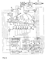
- Figure 3 is a schematic system diagram that illustrates the control of burning center and burnout points.
- the information on the incineration occurring inside the furnace from scanning-type infrared radiation thermometer 30 is inputted to an image processing part 40, which constitutes a automatic combustion control unit 24.
- detecting signals obtained by an 02 analyzer 32 and the like, a gas thermometer 29 and a layer thickness meter 28 and the like are also inputted to the total air volume computation part 41 and burning center control part 49 of the automatic combustion control unit 24.
- the information data regarding the inside of the furnace processed at the afore-mentioned image processing part 40 is inputted to the zone temperature distribution assessment part 42, where the temperature distribution, burning center position (the position of the highest temperature) and burnout point inside the furnace are assessed.
- the distribution volume of the primary combustion air A1 is computed at the distribution air volume computation part 43 based on the temperature distribution inside the furnace obtained at the zone temperature distribution assessment part 42, and so the temperature distribution inside the furnace can be adjusted to the temperature distribution set in advance by making the dampers 19a ⁇ 19g open or close through the air- adjusting device control part 44. Furthermore, based on signals outputted from the waste layer thickness meter 28 and the afore-mentioned burning center position, the waste feeder 5 and stoker driving device 17 are adjusted respectively through the burning center control part 49, waste forwarding control part 38 and waste feeding control part 37. Thus the waste forwarding velocity and waste feeding volume can be controlled, so that the waste layer level on the drying stoker 4a and burning center position on the combustion stoker 4b are positioned within a set range.
- the automatic combustion control unit 24 is equipped with the afore-mentioned waste quality and heat input computation part 36, combustion gas control part 36, boiler steam flow rate control part 47 , total air feeding control part 48 and the like as shown in Figure 2.
- detecting signals from the boiler steam pressure gauge and thermometer 34 and steam flow meter 35 are inputted to the boiler steam flow rate control part 47, to compute the volume of steam generated, and the heat input of the waste required to generate steam.
- operating signals are transmitted to the devices 5, 17, 11 and the like from the waste feeding control part 37, waste forwarding control part 38, total air feeding control part 48 and the like to acquire the heat input needed.
- combustion gas control part 46 is for controlling the operation of the fan 13 to draw the re-circulating combustion gas G' fed into the combustion chamber.
- the volume of the primary combustion air A1 c fed to the burnout stoker 4c is controlled so that the re-circulating combustion gas G' having oxygen concentration of 15% or more can be fed to the blowing nozzle of re-circulating combustion gas 12b .
- the temperature of the above-mentioned re-circulating combustion gas G' is continuously detected with the gas thermometer 45, and it is controlled to keep setting between 600 ⁇ 800°C by adjusting both the volume of the primary combustion air A1c fed underneath the burnout stoker 4c and waste feed rate of the stoker 4.
- the volume of the primary combustion air AC 1 fed underneath the burnout stoker 4c and the waste feed rate of the stoker 4 can be adjusted by measuring at least one of 02 concentration, CO concentration and HCl concentration in the re-circulating combustion gas G', thus making the measured value remain in the range of concentration set in advance.
- the volume of the above-mentioned re-circulating combustion gas G' is usually adjusted so that the NOx concentration in the secondary combustion gas Go is less than 60ppm at any time with the detecting signals coming from NOx analyzer 31. If the NOx concentration exceeds 60ppm, the feeding volume of the re-circulating combustion gas G' is increased to enhance the ability of mixing and stirring the re-circulating combustion gas G' in the reduction zone B.
- the operation of the above-mentioned secondary combustion air blower 16 is controlled by the total air volume computation part 41 and total air supplying volume control part 48, with the detecting signals from the 02 analyzer 32 provided at the combustion chamber outlet, so that the oxygen concentration of the secondary combustion gas Go typically comes to approximately 5%, and the total volume of the primary combustion air A1 and secondary combustion air A2 has been adjusted to the air volume of 1.3 as the air ratio.
- the feeding volume of the secondary combustion air A2 is reduced to 0.2 or less as the air ratio, complete secondary combustion cannot be performed because of its insufficient mixing with the primary combustion gas G. Accordingly, in order to solve this problem, even when the oxygen concentration in the secondary combustion gas Go exceeds 5%, the feeding volume of the secondary combustion air A2 should not be less than 0.2 as the air ratio.
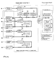
- FIG 4 is a basic block diagram that illustrates the combustion control system of the stoker-type waste incinerator employed with this embodiment.
- the combustion control system comprises a steady state control part D and a fuzzy control part E. That is, the steady state control part D controls stable combustion conditions in a steady state of the stoker-type waste incinerator, while the fuzzy control part E controls abnormal combustion conditions under non-steady state of the incinerator, to restore the abnormal combustion back to the steady state.
- the major elements that constitute the above-mentioned steady state control part D include waste heat input control D1, combustion center position control D2, burnout point control D3, air-waste ratio control D4, boiler steam flow rate control D5 , secondary combustion air real time control D6, re-circulating combustion gas control D7, and the like.
- waste heat input control D1 controls the velocity of the waste feeder 5 and stoker 4 to hold the volume of the waste (the waste heat input) fed into the furnace body to the set value.
- the air-waste ratio control D4 corrects the incorrect balance between the volume of the primary combustion air A1 and the waste volume by adjusting the velocity of the stoker 4.
- the boiler steam flow rate control D5 adjusts the volume of the primary combustion air A1, and the operating velocity of the waste feeder 5, the stoker 4 and the like in order that the boiler steam generation rate is held at the set value.
- the secondary combustion air real time control D6 adjusts the volume of the secondary combustion air A2 so that the value measured by the oxygen analyzer installed at the combustion chamber outlet is constant to the set value.
- the combustion center position control D2 and burnout point control D3 correct the incorrect combustion center and burnout position by adjusting both the volume of the primary combustion air A1 and the velocity of the stoker, or at least by adjusting one of them.
- the re-circulating combustion gas control D7 adjusts the volume of the re-circulating combustion gas G' drawn from the space above the burnout stoker 4c to keep NOx concentration of furnace outlet gas less than 60 ppm and correct the temperature of re-circulating combustion gas G', oxygen concentration, and the like.
- the above-mentioned fuzzy control part E checks the state of combustion by a plural number of parameters when the combustion becomes a so-called non-steady state due to the substantial and abrupt changes in the quantity and quality of the waste, and performs the restoration control of the non-steady state of combustion back to the steady state by outputting the control signal to correct the volume of combustion air and waste feed rate depending on the abnormal state by applying fuzzy-logical inferences with multivariable logics.
- the above-mentioned waste heat input control D1 and air-waste ratio control D4 are capable of dealing with a certain fluctuation of the quantity and quality of the waste.
- the waste W in the waste hopper 3 is continuously fed by the waste feeder 5 onto the drying stoker 4a on which the waste W is dried with the primary combustion air A1 fed from beneath the drying stoker 4a and radiation heat of the high-temperature combustion gas G generated with the combustion on the combustion stoker 4b in the next stage. Also, some combustion contents of the waste W on the drying stoker 4a starts gasification and combustion. Moisture in the waste W is evaporated, and unburned gas such as CO, HC and the like are released herewith.
- the dried waste W forwarded from the drying stoker 4a onto the combustion stoker 4b in succession is combusted with flames with the primary combustion air A1b fed from underneath the combustion stoker 4b,and burned out at the end part on the downstream side of the stoker 4b.
- the waste W burned out at the end part on the downstream side of the combustion stoker 4b is forwarded onto the burnout stoker in succession.
- the waste W is discharged from the ash discharge chute 9 as incinerated ashes not containing almost no unburned combustibles at all.
- the volume of the primary combustion air A1 fed underneath the stoker 4 is made to be 0.8 ⁇ 1.0 as the air ratio, and approximate 70% ⁇ 80% of the total primary combustion air A l is fed from underneath of the combustion stoker 4b, to form a reduction zone containing the unburned gas such as CO, HC and the like. Then, approximately 20% of the primary combustion air A1 is fed from underneath of the burnout stoker 4c to combust the unburned combustible contents of ash completely.
- the re-circulating combustion gas G' (temperature: 600°C ⁇ 800°C) above the burnout stoker 4c is sucked into the suction chamber 12a by the fan 13, and the re-circulating combustion gas G' which temperature is reduced by the heat exchanger (temperature: 200°C ⁇ 300° C) is blown into the combustion chamber on the upstream of the blow-in position of the secondary combustion air A2 (the combustion chamber on the lower side of the blowing nozzle of secondary combustion air gas 20b) from the blowing nozzle of re-circulating combustion gas 12b at high velocity (higher than 50m/s).
- the primary combustion gas G that has ascended from the primary combustion chamber 7 is mixed and stirred, thus the inside of the upstream of the blow-in position of the secondary combustion air A2 becomes a reduction zone B containing a weak reducing atmosphere.
- the secondary combustion air A2 is blown into the secondary combustion chamber 8 through the secondary combustion air nozzle 20b from the secondary combustion air blower 16.
- the primary combustion gas G containing the unburned gas and unburned combustibles is mixed and stirred twice with the re-circulating combustion gas G' blown in from the blowing nozzle of re-circulating combustion gas 12b and with the secondary combustion air A2. That is, the primary combustion gas G having varied components generated from the stokers 4a, 4b and 4c is mixed and stirred twice with the re-circulating combustion gas G' and secondary combustion air A2, thus making its composition and temperature distribution uniform, and sufficient mixing with the secondary combustion air A2 also being achieved.
- the unburned gas and unburned combustibles in the primary combustion gas G are completely combusted without a large volume of combustion air being blown into the furnace, and the generation of CO, dioxins, NOx and the like are sufficiently suppressed.
- CO at the furnace outlet ⁇ 10ppm, DXN ⁇ 0.5ngTEQ/m 3 N, NOx ⁇ 60ppm).
- the re-circulating combustion gas G' drawn from above the burnout stoker 4c contains more than 15% oxygen.
- the residual oxygen can effectively be utilized by blowing it into the primary combustion gas G. Because of low concentration of dust, HCl and the like which are corrosive, the heat exchanger 14 provided at the suction chamber 12a and fan13 are not damaged by corrosion.
- the primary combustion gas G containing the unburned gas and unburned combustibles is burned completely with the re-circulating combustion gas G' blown into the combustion chamber on the upstream of the blow-in position of the secondary combustion air A2 and with the secondary combustion air A blown into the secondary combustion chamber 8, it is discharged from the exhaust gas outlet 10 as the secondary combustion gas, and released in the atmosphere through the boiler, exhaust gas treatment facility and the like.
- the suction chamber 12a is provided with an air heater to be used as a heat exchanger 14.
- an air heater to be used as a heat exchanger 14.
- it can be replaced by an economizer, deaeration heater or superheater.
- a heat exchanger 14 is provided in the suction chamber 12a.
- the place where the heat exchanger 14 may be installed can be chosen, as desired.
- the volume of the primary combustion air to be fed from underneath the stoker can be set as 0.8 ⁇ 1.0 as the primary air ratio, and the combustion chamber can be made to be a strongly reducing atmosphere by drawing the re-circulating combustion gas G' having high oxygen concentration above on the downstream of the stoker to the outside, and the inside of the combustion chamber on the upstream side of the blow-in position of the secondary combustion air A2 can be made to be a mildly reducing atmosphere (a reduction zone B), in which the composition and temperature distribution of the primary combustion gas can be made uniform by blowing the re-circulating combustion gas G' having high oxygen concentration into the combustion chamber on the upstream of the blow-in position of the secondary combustion air A2.
- the unburned gas and unburned combustibles in the primary combusting gas G are typically burned over the 3 completely by blowing the secondary combustion air A2 into the secondary combustion chamber on the downstream of the afore-mentioned reduction zone B. It follows that the waste can be burned completely with the 3 stage combustion under a state of 1.3 or less as the total air ratio
- the combustion of waste is achieved by using a stoker-type waste incinerator equipped with a combustion control system comprising a steady state control part and fuzzy control part, hence not only achieving stable waste combustion in a steady state, but also being able to restore the abnormal state back to the steady state by the combustion control of the fuzzy control part, which responds to the case of abnormality promptly when abnormal situations such as substantial fluctuation in the quality and quantity of waste and the like occur.
Landscapes
- Engineering & Computer Science (AREA)
- Mechanical Engineering (AREA)
- General Engineering & Computer Science (AREA)
- Chemical & Material Sciences (AREA)
- Combustion & Propulsion (AREA)
- Incineration Of Waste (AREA)
Abstract
Description
- The present invention relates to improvements to a method of combusting municipal solid waste such as industrial waste, household solid waste and the like (hereinafter called waste) with a stoker-type waste incinerator. In particular, the present invention concerns improvements in such a method of combusting waste by using a stoker-type waste incinerator at a low air ratio. This enables the stoker-type waste incinerator to combust waste efficiently and perfectly whilst using a reduced amount of fed combustion air, to substantially reduce generation of toxic substances, to improve heat recovery efficiency, and to downsize the dimensions of both the stoker-type waste incinerator and exhaust gas treatment facilities.
- In most instances, disposal of municipal solid waste is performed by combusting it with waste incinerators. Waste incinerators commonly used include either stoker-type waste incinerators or fluidized bed-type waste incinerators, with the stoker-type waste incinerator being the most popular type.
- Figure 5 illustrates one example of a stoker-type waste incinerator. Said stoker-
type waste incinerator 50 comprises afurnace 51, awaste hopper 52, afeeder pusher 53, astoker 54, an under-stoker hopper 55, aprimary combustion chamber 56, asecondary combustion chamber 57, a primarycombustion air duct 58, a secondarycombustion air duct 59, anash discharge chute 60, anexhaust gas outlet 61 and the like. Thestoker 54 consists of a drying stoker 54a, acombustion stoker 54b and aburnout stoker 54c, to feed the primary combustion air A1 from underneath thestoker 54 tostokers - The waste W fed into the
waste hopper 52 is fed onto the drying stoker 54a in succession with afeeder pusher 53, and then heated and dried with primary combustion air A1 fed from underneath the drying stoker 54a and also with radiant heat from the upper-positionedprimary combustion chamber 56 at elevated temperatures. Thus, moisture and volatile components in the waste W are evaporated and unburned gas (reduction gas) such as CO (carbon oxides), HC (hydrocarbon) and the like are released. - Dried waste W is conveyed from the drying stoker 54a to the
combustion stoker 54b, and burned in flames with primary combustion air A1b fed from its underneath thereon. It reaches the burnout position just at the end part on the downstream side of thecombustion stoker 54b. Then, the waste W burned out in proximity to the end part of the downstream side of thecombustion stoker 54b is conveyed onto theburnout stoker 54c. Next, after so-called embers are burnt with primary combustion air Alc fed from underneath theburnout stoker 54c, the incineration residues (having typically unburned combustibles content of 5% or less) are discharged from theash discharge chute 60 downward. - On the other hand, primary combustion gas G, containing the unburned gas and unburned combustibles, which were generated while drying and burning the waste W, flows into the
second combustion chamber 57 that is installed above theprimary combustion chamber 50. It is, then, discharged from theexhaust gas outlet 61 to the outside after so-called secondary combustion has been performed in thesecondary combustion chamber 57 by feeding the secondary combustion air A2, to achieve complete combustion. - There is a strong demand for waste incineration using a stoker-type waste incinerator in which (1) complete combustion can be achieved surely, automatically and at ease by using an incinerator small in size and with high efficiency, (2) toxic substances are not discharged to the outside when the waste is incinerated, and (3) the purification treatment of the secondary combustion gas is simply performed with a small-type purification treatment device.
- On the other hand, with the above-mentioned stoker-
type waste incinerator 50 shown in Figure 5, it is found that compositions and temperatures of the combustion gas generated while waste W is combusted differ depending on where it is combusted. Thus, generally a zone is formed where the combustion gas containing a large quantity of the unburned gas such as CO and the like is generated, a further zone is formed where the combustion gas containing a large quantity of NOx is generated with intensive burning, and a yet a further zone is formed where the low temperature combustion gas of 500~700° C containing the residual oxygen of more than 15% with the excess air, thus making the combustion gas inside theprimary combustion chamber 56 to be in such a state that the distribution of compositions and temperatures is found not to be uniform. - Therefore, with stoker-
type waste incinerator 50, it has been imperative that the unevenly distributed primary combustion gas is mixed and stirred in order to make the combustion gas uniform enough for the unburned gas to be burned completely. - To mix and stir the above-mentioned primary combustion gas, a method has been utilized (1) with which part of the exhaust combustion gas is blown into the waste incinerator as a re-circulating combustion gas after the complete combustion and purification treatment, and for (2) with which the secondary combustion air (or the temperature adjusting air) is injected, and/or (3) with which blow-in of the re-circulating combustion gas and blow-in of the secondary combustion gas are combined.
- With the above-mentioned methods, there has typically been the problem that the amount of exhaust combustion gas discharged from the incinerator inevitably increases because either the re-circulating combustion gas or air, or both, are blown in a large volume into the incinerator, thus resulting in the facilities used, such as the exhaust gas treatment device installed downstream of the stoker-
type waste incinerator 50, being made bulky.
Furthermore, with the waste combustion for which a conventional stoker-type incinerator is employed, the generation of NOx increases when the feeding volume of the primary combustion air is raised to control the generation of the unburned gas such as CO and the like in order that a lesser amount of toxic substances, such as dioxins, is discharged. Conversely, the generation of dioxins increases, when the feeding volume of the primary combustion air is lowered in order to suppress the generation of NOx, because a greater volume of unburned gas such as CO and the like is discharged. Thus, there remain many unsolved difficulties with such combustion control. - For example, with a waste incinerator equipped with a power generating unit, it is strongly required that (a) heat recovery can be achieved efficiently in a boiler, (b) the steam flow rate of the boiler and temperatures inside the waste incinerator remain in the set range, and (c) the combustion control of waste is performed to suppress the generation of dioxins, NOx and the like.
To meet these requirements, generally the steam flow rate of the boiler, temperatures inside the furnace, O2, CO and NOx concentration in the secondary combustion gas are detected such that, the volume of the primary and secondary combustion air, the distribution of the primary combustion air to the stokers and the operating velocity of the stokers can be adjusted.
However, with the above-mentioned conventional method of combustion control, so-called real time combustion control is impossible, thus causing the delay in control because the values detected at the position on the downstream side of the waste combusted are used for controlling the waste combustion. - Furthermore, with a stoker-type waste incinerator, when a state of combustion turns out to be a so-called non-steady state, due to the substantial fluctuation in the composition and excess or insufficient supply of waste, automatic combustion control does not function because the responsibility of combustion control varies vastly from steady state combustion.
- It is an object of the present invention to solve the afore-mentioned problems with regard to methods of combusting waste using a conventional stoker-type waste incinerator, such as (1) the difficulty in combusting the waste while reducing the generation of toxic substances together with the use of the least amount of combustion air, (2) the difficulty in downsizing a purification treatment unit for the secondary combustion gas, because the volume of the secondary combustion gas from the waste incinerator increases when the primary combustion gas is mixed and stirred by re-circulating the secondary combustion gas and the like, and (3) the difficulty in holding the waste combustion promptly in a more desirable state of combustion by responding to the fluctuation of the composition and form of the waste on the stokers.
Further, it is also an object of the present invention to provide a method of combusting waste at a low air ratio with a stoker-type waste incinerator with which stable, complete combustion of the waste can be performed at a low air ratio regardless of the fluctuation in the quality of the waste whilst achieving a substantial reduction in discharging toxic matters. This is to be obtained in a manner that combustion gas with high oxygen concentration can be drawn from the range where the burnout stoker in the primary combustion chamber of the stoker-type waste incinerator, and the combustion gas drawn is fed to the primary combustion gas underneath the feeding position of the secondary combustion air, that is, on the upstream side. Thus a mixing, stirring and reduction zone of the primary combustion gas is formed. Further, blowing in the least amount of the secondary air to achieve complete combustion. And for the combustion control of waste, a steady state control part mainly responsible at least for the combustion control in normal operating conditions including the control of heat inputs of the waste fed, the control of the combustion-center and burnout position and the real time control of the secondary combustion air and a fuzzy control part responsible for restoring the abnormal combustion to the steady state of combustion when the abnormal combustion of waste happens can be employed. - To achieve the object of the afore-mentioned invention, the present invention in one aspect provides a method of combusting waste according to
claim 1. - Preferred features are shown in the accompanying subsidiary claims.
The present invention will now be illustrated by way of the following nonlimiting example, with reference to the accompanying drawings, in which: - Figure 1 is a whole block diagram of a stoker-type waste incinerator employed in one embodiment of the present invention;
- Figure 2 is a system diagram to illustrate the outline of the measurement of the heat input of the waste and the control of waste feeding with the stoker-type waste incinerator according to one embodiment of the present invention;
- Figure 3 is a system diagram to illustrate the outline of the control of combustion center burnout points with the stoker-type waste incinerator according to one embodiment of the present invention;
- Figure 4 is a block diagram to illustrate the basic constitution of the combustion control system with the stoker-type waste incinerator according to one embodiment of the present invention; and
- Figure 5 is an explanatory drawing of a conventional stoker-type waste incinerator as an example of the prior art.
-
- W
- Waste
- G
- Primary combustion gas
- Go
- Secondary combustion gas
- G'
- Re-circulating combustion gas (Combustion gas in a zone on the downstream side of a stoker)
- A1
- Primary combustion air
- A2
- Secondary combustion air
- A
- Preheated fresh air
- B
- Reduction zone
- D
- Steady state control part
- E
- Fuzzy control part
- 1
- Stoker-type waste incinerator
- 2
- Furnace body
- 3
- Waste hopper
- 4
- Stoker
- 4a
- Drying stoker
- 4b
- Combustion stoker
- 4d
- Burnout stoker
- 5
- Waste feeder
- 5a
- Waste feeder controller
- 6
- Under-stoker hopper
- 7
- Primary combustion chamber
- 8
- Secondary combustion chamber
- 9
- Ash discharge chute
- 10
- Exhaust gas outlet
- 11
- Primary combustion air blower
- 12
- Duct of re-circulating combustion gas
- 12a
- Suction chamber
- 12b
- Blowing nozzle of re-circulating combustion gas
- 13
- Fan
- 13a
- Driving part of the fan
- 14
- Heat exchanger
- 15
- Air duct
- 16
- Secondary combustion air blower
- 16a
- Driving part of the secondary combustion air blower
- 16b
- Blowing nozzle of secondary combustion air
- 17
- Stoker driving device
- 17a
- Stoker driving device controller
- 18
- Damper
- 18a
- Damper controller
- 19a~19g
- Dampers
- 20
- Damper controller
- 21
- Heat recovery boiler
- 22
- Boiler drum
- 23
- Exhaust gas treatment equipment
- 24
- Automatic combustion control unit
- 25
- Waste scale
- 26
- Scanning laser-type level meter
- 28
- Waste layer thickness meter
- 29
- Gas thermometer
- 30
- Scanning-type infrared radiation thermometer
- 31
- NOx analyzer
- 32
- 02 analyzer
- 33
- CO analyzer (Dioxins precursor analyzer)
- 34
- Steam pressure gauge and thermometer
- 35
- Steam flow meter
- 36
- Waste quality and heat inputs computation part
- 37
- Waste feeding control part
- 38
- Waste forwarding control part
- 39
- 02 analyzer
- 40
- Image processing part
- 41
- Total air volume computation part
- 42
- Zone temperature distribution assessment part
- 43
- Distribution air volume computation part
- 44
- Air adjustment device control part
- 45
- Gas thermometer
- 46
- Combustion gas control part
- 47
- Boiler steam flow rate control part
- 48
- Total air supplying volume control part
- 49
- Combustion center control part
- Figure 1 illustrates an example of a stoker-
type waste incinerator 1 for carrying out the method according to the present invention. Said stoker-type waste incinerator 1 comprises afurnace body 2 formed with a furnace wall, awaste hopper 3 in which waste W is fed, astoker 4 for burning waste W, awaste feeder 5 to feed waste W onto thestoker 4, an under-stoker hopper 6 installed underneath thestoker 4, a combustion chamber (reference number omitted) consisting of a primary combustion chamber 7 formed above thestoker 4 and a secondary combustion chamber 8 formed above the primary combustion chamber 7, anash discharge chute 9 for discharging incineration ashes. Aexhaust gas outlet 10 is present for discharging the secondary combustion gas Go, a primarycombustion air blower 11 feeds the primary combustion air A1 into the primary combustion chamber 7 from beneath thestoker 4, a duct ofre-circulating combustion gas 12 leads the re-circulating combustion gas G', drawn from the primary combustion chamber 7 on the downstream side of thestoker 4, to the outside of the primary combustion chamber 7, into the combustion chamber on the upstream side of the blow-in position of the secondary combustion air A2. Afan 13 is located within the duct ofre-circulating combustion gas 12, a heat exchanger 14 is provided in the duct ofre-circulating combustion gas 12 on the upstream side of thefan 13. Anair duct 15 is connected to the heat exchanger and the like to take out fresh air A preheated by the heat exchanger, a secondarycombustion air blower 16, astoker driving device 17 to actuate thestoker 4, anddampers - Referring again to Figure 1, 5a designates a driving part of the waste feeder(waste feeder controller), 11a a driving part of the primary combustion air blower(primary combustion air blower controller), 13a a driving part of the fan, 16a a driving part of the secondary combustion air blower(secondary combustion air blower controller), 17a a stoker driving device controller, and 18a.20 damper controllers.
Also, referring to Figure 1, 21 designates a waste heat recovery boiler, 22 a boiler drum, 23 an exhaust gas treatment equipment, and 24a an automatic combustion control unit.
Furthermore in Figure 1, 25 designates a waste scale, 26 a scanning laser-type level meter, 28 a waste layer thickness meter, 29 a gas thermometer, 30 a scanning-type infrared radiation thermometer, 31 a NOx analyzer, 32 an 02 analyzer, 33 a CO analyzer, 34 a steam pressure gauge and thermometer and 35 a steam flow meter. - The above-mentioned
stoker 4 comprises a dryingstoker 4a, acombustion stoker 4b and aburnout stoker 4c, and an under-stoker hopper 6 is located underneath thestokers stoker stoker 4 is moved forward from the upstream side to the downstream side while stirring it in a reciprocating motion of travelling grates back and forth with a certain pitch by thestoker driving device 17.
Above thestoker 4, there is provided a primary combustion chamber 7 for drying and combusting the waste W while it moves forward on thestoker 4 with primary combustion air A1a~A1c fed from underneath thestoker 4. Also provided therewith is a secondary combustion chamber 8 for combusting the unburned gas such as CO and the like and unburned combustibles generated in the primary combustion chamber with secondary combustion air A2. - The above-mentioned primary
combustion air blower 11 which is for supplying the primary combustion air A1 to the lower part of thestokers stoker hoppers 6 under thestoker 4, is equipped with a plural number of airvolume adjusting dampers 19a~19g. Further,damper controllers 20 control the opening/closing of thesedampers 19a~19g with which the amount of the primary combustion air A1 fed to the lower part of thestoker - According to this embodiment, the amount of the primary combustion air A1 fed from underneath the
stoker 4 is controlled, typically the primary air ratio (the amount of the primary combustion air/the amount of the theoretical combustion air) being 0.8~1.0. And, usually approximately 70~80% of the primary combustion air A1 is fed from thecombustion stoker 4b, to form the reduction zone containing the unburned gas, such as CO, HC and the like above thecombustion stoker 4b, so that the space above thecombustion stoker 4b is made to be the atmosphere inhibiting to the generation of NOx. Meanwhile approximately 20% of the primary combustion air A1c is fed from theburnout stoker 4c, to achieve complete combustion of the unburned combustibles in the ashes. - The distribution amount and temperature of the primary combustion air A1a~A1c fed to the lower part of
stokers burnout stoker 4c to be a value set generally between 600~800°C. - The above-mentioned duct of
re-circulating combustion gas 12 is for leading the re-circulating combustion gas G' on the upper part on the downstream side of the stoker 4 (the upper part of theburnout stoker 4c) being drawn to the outside of the primary combustion chamber 7 into the combustion chamber on the upstream side of the blow position of the secondary combustion air A2. In particular, by forming asuction chamber 12a on the furnace wall above theburnout stoker 4c to draw out the combustion gas G' above theburnout stoker 4, the re-circulating combustion gas G' above theburnout stoker 4c is sucked into thesuction chamber 12a by usingfan 13, and the re-circulating combustion gas G' is blown into the combustion chamber at high velocity from the blowing nozzle ofre-circulating combustion gas 12b on the upstream side of the blow-in position of the secondary combustion air A2. - The re-circulating combustion gas G' above the
burnout stoker 4c is drawn to the outside of the furnace, and the drawn re-circulating combustion gas G' is blown into the combustion chamber on the upstream side of the blow-in position of the secondary combustion air A2 to mix and stir the primary combustion gas G generated inside the primary combustion chamber 7. In this way a slightly reducing atmosphere (reduction zone B) where the composition and temperatures of the primary combustion gas G become uniform is formed at a region of the combustion chamber upstream of the blow-in position of the secondary combustion air A2 to prevent the generation of NOx, and to combust unburned gas and the like completely by supplying the minimum amount of secondary combustion air A2 thereafter. - According to the present embodiment, the retention time of the afore-mentioned primary combustion gas G is such that at the reduction zone B (i.e. the time required to pass the reduction zone B) is typically 0.5 seconds or longer, and generally it can retain in the high temperature zone of higher than 850°C for 1.5 seconds or longer after supplying secondary combustion air.
- The above-mentioned heat exchanger 14 is provided in the duct of
re-circulating combustion gas 12 on the upstream side of the fan 13 (with this example, inside thesuction chamber 12a) to reduce the temperature of the re-circulating combustion gas G'. An economizer, deaeration heater, boiler, air heater and the like can typically be employed as such a heat exchanger 14. - Corrosive gases such as HCl, SOx and the like, in the afore-mentioned primary combustion gas, are generated when plastics such as polyvinyl chloride and the like, contained in waste W, are combusted. Plastics are mainly burned on the
combustion stoker 4b because they are decomposed and are generally burned at temperatures of 350°C~500°C at a relatively high velocity of combustion. Accordingly, corrosive gases are mainly generated on thecombustion stoker 4b, and found in the primary combustion gas G above thecombustion stoker 4b and dryingstoker 4a, while the re-circulating combustion gas G' above theburnout stoker 4c has a lesser concentration of corrosive gas and dust, thus allowing the afore-mentioned heat exchanger 14 to be provided inside thesuction chamber 12a so as to draw the re-circulating combustion gas G' above theburnout stoker 4c. And, there are caused no problems such as corrosion and the like even when the re-circulating combustion gas G' which temperatures are reduced to 200°C~300°C is blown into the secondary combustion chamber 8 by thefan 13. - The afore-mentioned secondary
combustion air blower 16 is for supplying the secondary combustion air A2 to the blowing nozzles of secondary combustion air16b formed on the furnace wall of the secondary combustion chamber 8. - The volume of the secondary combustion air A2 blown into the secondary combustion chamber 8 is adjusted by means of a
damper 18. In this embodiment, the volume of the secondary combustion air A2 fed into the secondary combustion chamber 8 is set at 0.3~0.4 as its secondary air ratio (the secondary combustion air volume/the theoretical combustion air volume), and the total volume of the primary combustion air A1 and secondary combustion air A2 is set at 1.3 as its air ratio. Accordingly, the oxygen concentration of the secondary combustion gas Go is continuously measured at real time by the laser-type oxygen analyzer 32 and the volume of the secondary combustion air is controlled to make the oxygen concentration to be approximately 5% (dry). - Figure 2 is a schematic system diagram that illustrates a heat input measuring device and a waste feeding controller for which a below mentioned
waste scale 25 and a scanning laser-type level meter 26 are employed.
Thewaste scale 25 can be used for measuring the weight of waste picked up by a crane C, and the measured data are inputted to the waste quality and heatinput computation part 36.
The data on the waste volume in thewaste hopper 3 obtained by the scanning laser-type level meter 26 installed above thewaste hopper 3 is also inputted to the waste quality and heatinput computation part 36. - In the waste quality and heat
input computation part 36, the waste quality (heat value) is estimated based on the specific gravity of the waste computed by both afore-mentioned inputted volume and weight of the waste and stored each time the waste is fed.
Also, changes in the total volume of the waste per unit time are computed from the total volume of the waste stored in thewaste hopper 3, and the moving volume of the waste (that is, the fluctuation rate of the volume of the waste in the hopper) is determined by the changes in the total volume of the waste per unit time, thus the heat input of the waste per unit time is computed from the moving volume and the heat value predicted from the afore-mentioned specific gravity. - Data regarding the heat input of the waste is inputted to the waste
feeding control part 37 which controls thewaste feeder controller 5a of thewaste feeder 5. Thewaste feeder 5 andstoker driving device 17 are controlled by the wastefeeding control part 37 to make the heat input of the waste fed into the stoker-type waste incinerator constant at the setting value. - Figure 3 is a schematic system diagram that illustrates the control of burning center and burnout points.
The information on the incineration occurring inside the furnace from scanning-typeinfrared radiation thermometer 30 is inputted to animage processing part 40, which constitutes a automaticcombustion control unit 24. Similarly, detecting signals obtained by an 02analyzer 32 and the like, agas thermometer 29 and alayer thickness meter 28 and the like are also inputted to the total airvolume computation part 41 and burningcenter control part 49 of the automaticcombustion control unit 24.
The information data regarding the inside of the furnace processed at the afore-mentionedimage processing part 40 is inputted to the zone temperaturedistribution assessment part 42, where the temperature distribution, burning center position (the position of the highest temperature) and burnout point inside the furnace are assessed. - Further, the distribution volume of the primary combustion air A1 is computed at the distribution air
volume computation part 43 based on the temperature distribution inside the furnace obtained at the zone temperaturedistribution assessment part 42, and so the temperature distribution inside the furnace can be adjusted to the temperature distribution set in advance by making thedampers 19a~19g open or close through the air- adjustingdevice control part 44.
Furthermore, based on signals outputted from the wastelayer thickness meter 28 and the afore-mentioned burning center position, thewaste feeder 5 andstoker driving device 17 are adjusted respectively through the burningcenter control part 49, wasteforwarding control part 38 and wastefeeding control part 37. Thus the waste forwarding velocity and waste feeding volume can be controlled, so that the waste layer level on the dryingstoker 4a and burning center position on thecombustion stoker 4b are positioned within a set range. - The automatic
combustion control unit 24 is equipped with the afore-mentioned waste quality and heatinput computation part 36, combustiongas control part 36, boiler steam flowrate control part 47 , total airfeeding control part 48 and the like as shown in Figure 2. - Further, detecting signals from the boiler steam pressure gauge and
thermometer 34 andsteam flow meter 35 are inputted to the boiler steam flowrate control part 47, to compute the volume of steam generated, and the heat input of the waste required to generate steam. Thus, operating signals are transmitted to thedevices feeding control part 37, wasteforwarding control part 38, total airfeeding control part 48 and the like to acquire the heat input needed. - In addition, the above-mentioned combustion
gas control part 46 is for controlling the operation of thefan 13 to draw the re-circulating combustion gas G' fed into the combustion chamber. With the signals from the 02analyzer 39, the volume of the primary combustion air A1 c fed to theburnout stoker 4c is controlled so that the re-circulating combustion gas G' having oxygen concentration of 15% or more can be fed to the blowing nozzle ofre-circulating combustion gas 12b . - Furthermore, the temperature of the above-mentioned re-circulating combustion gas G' is continuously detected with the
gas thermometer 45, and it is controlled to keep setting between 600~800°C by adjusting both the volume of the primary combustion air A1c fed underneath theburnout stoker 4c and waste feed rate of thestoker 4. - Though not shown in Figure 3, the volume of the primary
combustion air AC 1 fed underneath theburnout stoker 4c and the waste feed rate of thestoker 4 can be adjusted by measuring at least one of 02 concentration, CO concentration and HCl concentration in the re-circulating combustion gas G', thus making the measured value remain in the range of concentration set in advance. - In addition, the volume of the above-mentioned re-circulating combustion gas G' is usually adjusted so that the NOx concentration in the secondary combustion gas Go is less than 60ppm at any time with the detecting signals coming from
NOx analyzer 31. If the NOx concentration exceeds 60ppm, the feeding volume of the re-circulating combustion gas G' is increased to enhance the ability of mixing and stirring the re-circulating combustion gas G' in the reduction zone B. - The operation of the above-mentioned secondary
combustion air blower 16 is controlled by the total airvolume computation part 41 and total air supplyingvolume control part 48, with the detecting signals from the 02analyzer 32 provided at the combustion chamber outlet, so that the oxygen concentration of the secondary combustion gas Go typically comes to approximately 5%, and the total volume of the primary combustion air A1 and secondary combustion air A2 has been adjusted to the air volume of 1.3 as the air ratio. - Taking into consideration both the mixing capability of the primary combustion gas G and the secondary combustion of incombustibles, it is necessary to supply a certain volume of the above-mentioned secondary combustion air A2. Namely, when the feeding volume of the secondary combustion air A2 is reduced to 0.2 or less as the air ratio, complete secondary combustion cannot be performed because of its insufficient mixing with the primary combustion gas G. Accordingly, in order to solve this problem, even when the oxygen concentration in the secondary combustion gas Go exceeds 5%, the feeding volume of the secondary combustion air A2 should not be less than 0.2 as the air ratio.
- Figure 4 is a basic block diagram that illustrates the combustion control system of the stoker-type waste incinerator employed with this embodiment. The combustion control system comprises a steady state control part D and a fuzzy control part E.
That is, the steady state control part D controls stable combustion conditions in a steady state of the stoker-type waste incinerator, while the fuzzy control part E controls abnormal combustion conditions under non-steady state of the incinerator, to restore the abnormal combustion back to the steady state. - As shown in Figure 4, the major elements that constitute the above-mentioned steady state control part D include waste heat input control D1, combustion center position control D2, burnout point control D3, air-waste ratio control D4, boiler steam flow rate control D5 , secondary combustion air real time control D6, re-circulating combustion gas control D7, and the like.
- Namely, waste heat input control D1 controls the velocity of the
waste feeder 5 andstoker 4 to hold the volume of the waste (the waste heat input) fed into the furnace body to the set value. The air-waste ratio control D4 corrects the incorrect balance between the volume of the primary combustion air A1 and the waste volume by adjusting the velocity of thestoker 4. Furthermore, the boiler steam flow rate control D5 adjusts the volume of the primary combustion air A1, and the operating velocity of thewaste feeder 5, thestoker 4 and the like in order that the boiler steam generation rate is held at the set value. The secondary combustion air real time control D6 adjusts the volume of the secondary combustion air A2 so that the value measured by the oxygen analyzer installed at the combustion chamber outlet is constant to the set value. The combustion center position control D2 and burnout point control D3 correct the incorrect combustion center and burnout position by adjusting both the volume of the primary combustion air A1 and the velocity of the stoker, or at least by adjusting one of them.
The re-circulating combustion gas control D7 adjusts the volume of the re-circulating combustion gas G' drawn from the space above theburnout stoker 4c to keep NOx concentration of furnace outlet gas less than 60 ppm and correct the temperature of re-circulating combustion gas G', oxygen concentration, and the like. - On the other hand, the above-mentioned fuzzy control part E checks the state of combustion by a plural number of parameters when the combustion becomes a so-called non-steady state due to the substantial and abrupt changes in the quantity and quality of the waste, and performs the restoration control of the non-steady state of combustion back to the steady state by outputting the control signal to correct the volume of combustion air and waste feed rate depending on the abnormal state by applying fuzzy-logical inferences with multivariable logics.
- Concretely, for example, the above-mentioned waste heat input control D1 and air-waste ratio control D4 are capable of dealing with a certain fluctuation of the quantity and quality of the waste. However, when the extreme changes happen, it is necessary to control volume of the combustion air and the velocity of the stoker extremely fast and widely by using the fuzzy control part E.
- Next, a method of waste combustion at the low air ratio by employing the stoker-
type waste incinerator 1 according to the present embodiment is explained. Referring to Figure 1 to Figure 4 inclusive, whilst the waste W fed into the furnace from thewaste hopper 3 is gasified and combusted while it moves forward on the dryingstoker 4a,combustion stoker 4b andburnout stoker 4c in succession, with supplying the primary combustion air A1 which is fed into the primary combustion chamber 7 through thestokers combustion air blower 11. - Thus, the waste W in the
waste hopper 3 is continuously fed by thewaste feeder 5 onto the dryingstoker 4a on which the waste W is dried with the primary combustion air A1 fed from beneath the dryingstoker 4a and radiation heat of the high-temperature combustion gas G generated with the combustion on thecombustion stoker 4b in the next stage. Also, some combustion contents of the waste W on the dryingstoker 4a starts gasification and combustion. Moisture in the waste W is evaporated, and unburned gas such as CO, HC and the like are released herewith. - The dried waste W forwarded from the drying
stoker 4a onto thecombustion stoker 4b in succession is combusted with flames with the primary combustion air A1b fed from underneath thecombustion stoker 4b,and burned out at the end part on the downstream side of thestoker 4b.
The waste W burned out at the end part on the downstream side of thecombustion stoker 4b is forwarded onto the burnout stoker in succession. Then, after so-called embers burning with the primary combustion air Alc fed from underneath theburnout stoker 4c, the waste W is discharged from theash discharge chute 9 as incinerated ashes not containing almost no unburned combustibles at all. - With the stoker-
type waste incinerator 1, the volume of the primary combustion air A1 fed underneath thestoker 4 is made to be 0.8~1.0 as the air ratio, and approximate 70%~80% of the total primary combustion air A l is fed from underneath of thecombustion stoker 4b, to form a reduction zone containing the unburned gas such as CO, HC and the like. Then, approximately 20% of the primary combustion air A1 is fed from underneath of theburnout stoker 4c to combust the unburned combustible contents of ash completely. - According to the invention, the re-circulating combustion gas G' (temperature: 600°C~800°C) above the
burnout stoker 4c is sucked into thesuction chamber 12a by thefan 13, and the re-circulating combustion gas G' which temperature is reduced by the heat exchanger (temperature: 200°C~ 300° C) is blown into the combustion chamber on the upstream of the blow-in position of the secondary combustion air A2 (the combustion chamber on the lower side of the blowing nozzle of secondary combustion air gas 20b) from the blowing nozzle ofre-circulating combustion gas 12b at high velocity (higher than 50m/s). By doing so, the primary combustion gas G that has ascended from the primary combustion chamber 7 is mixed and stirred, thus the inside of the upstream of the blow-in position of the secondary combustion air A2 becomes a reduction zone B containing a weak reducing atmosphere. Then, the secondary combustion air A2 is blown into the secondary combustion chamber 8 through the secondary combustion air nozzle 20b from the secondarycombustion air blower 16.
By controlling the volume of the secondary combustion air A2 to keep oxygen concentration of secondary combustion gas which is measured at real time with a laser type oxygen analyser, the total air ratio of the primary air A1 and secondary air A2.is kept 1.3. - The primary combustion gas G containing the unburned gas and unburned combustibles is mixed and stirred twice with the re-circulating combustion gas G' blown in from the blowing nozzle of
re-circulating combustion gas 12b and with the secondary combustion air A2. That is, the primary combustion gas G having varied components generated from thestokers - The re-circulating combustion gas G' drawn from above the
burnout stoker 4c contains more than 15% oxygen. The residual oxygen can effectively be utilized by blowing it into the primary combustion gas G. Because of low concentration of dust, HCl and the like which are corrosive, the heat exchanger 14 provided at thesuction chamber 12a and fan13 are not damaged by corrosion. - After the primary combustion gas G containing the unburned gas and unburned combustibles is burned completely with the re-circulating combustion gas G' blown into the combustion chamber on the upstream of the blow-in position of the secondary combustion air A2 and with the secondary combustion air A blown into the secondary combustion chamber 8, it is discharged from the
exhaust gas outlet 10 as the secondary combustion gas, and released in the atmosphere through the boiler, exhaust gas treatment facility and the like. - In the above-mentioned embodiment, the
suction chamber 12a is provided with an air heater to be used as a heat exchanger 14. However, it can be replaced by an economizer, deaeration heater or superheater. - Also, in the above-mentioned embodiment, a heat exchanger 14 is provided in the
suction chamber 12a. However, the place where the heat exchanger 14 may be installed can be chosen, as desired. - In the combustion method according to the present invention the volume of the primary combustion air to be fed from underneath the stoker can be set as 0.8~1.0 as the primary air ratio, and the combustion chamber can be made to be a strongly reducing atmosphere by drawing the re-circulating combustion gas G' having high oxygen concentration above on the downstream of the stoker to the outside, and the inside of the combustion chamber on the upstream side of the blow-in position of the secondary combustion air A2 can be made to be a mildly reducing atmosphere (a reduction zone B), in which the composition and temperature distribution of the primary combustion gas can be made uniform by blowing the re-circulating combustion gas G' having high oxygen concentration into the combustion chamber on the upstream of the blow-in position of the secondary combustion air A2. Furthermore, the unburned gas and unburned combustibles in the primary combusting gas G are typically burned over the 3 completely by blowing the secondary combustion air A2 into the secondary combustion chamber on the downstream of the afore-mentioned reduction zone B. It follows that the waste can be burned completely with the 3 stage combustion under a state of 1.3 or less as the total air ratio
- As a result, complete combustion of the unburned gas, unburned combustibles, and the like has been achieved with the small volume of combustion air of 1.3 as the total air ratio, thus resulting in substantial reduction of the secondary combustion gas Go and in downsizing of the exhaust gas treatment facilities, and the like. Further, CO, NOx and dioxins are remarkably reduced because the unburned gas and unburned combustibles are completely combusted. Furthermore, heat loss of exhaust gas is also lowered because the volume of the exhaust gas is reduced, thus enhancing the heat recovery efficiency.
- In addition, according to the present invention, the combustion of waste is achieved by using a stoker-type waste incinerator equipped with a combustion control system comprising a steady state control part and fuzzy control part, hence not only achieving stable waste combustion in a steady state, but also being able to restore the abnormal state back to the steady state by the combustion control of the fuzzy control part, which responds to the case of abnormality promptly when abnormal situations such as substantial fluctuation in the quality and quantity of waste and the like occur.
Claims (10)
- A method of combusting waste (W) with a stoke-type waste incinerator (1) at a low air ratio; characterized in that said waste (W) is shifted from a drying stoker (4a) to a combustion stoker (4b), to a burnout stoker (4d), in succession for the primary combustion of said waste (W), said waste (W) being placed on stokers (4) of said incinerator, said combustion effected by feeding primary combustion air (A1) from underneath said stokers (4) to a primary combustion chamber (7) above said stokers (4), said combustion being effected also for the unburned gas and unburned combustibles contained in the primary combustion gas (G) flowing in from said primary combustion chamber (7) being combusted by feeding secondary combustion air (A2) into a secondary combustion chamber (8) placed above the primary combustion chamber (7); further characterized in that the volume of said primary combustion air (A1) fed from beneath said stokers (4) is held to allow the air ratio to be 0.8~1.0, re-circulating combustion gas (G')having oxygen concentration of 15% or more is drawn to the outside from said primary combustion chamber (7) in the zone where said burnout stoker (4d) is positioned, and said drawn re-circulating combustion gas (G') is blown into said primary combustion gas (G) flowing in from said primary combustion chamber (7) at the upstream of a feeding position of said secondary combustion air (A2) for mixing and stirring said primary combustion gas (G) with the re-circulating combustion gas (G') blown in, thus forming a high-temperature reduction zone with an air ratio of 0.8~1.0 and also with a uniform distribution of composition and temperature of gas flow; and furthermore characterized in that the feeding volume of said secondary combustion air (A2) is held to allow the air ratio to be 0.3~0.4, the oxygen concentration of the secondary combustion gas (Go) at the outlet of said secondary combustion chamber (8) being measured continuously at real time, by using a laser-type oxygen analyzer, to control the feeding amount of said secondary combustion air (A2) so that the measured value of said oxygen concentration becomes substantially 5%, thus achieving a complete combustion of waste (W) with a total air ratio of less than 1.3; and yet further characterized in that the combustion control system comprises a steady state control part (D) responsible for the stable combustion control in normal operating conditions including at least: the control of the heat input of the waste (W), the control of the burning-center and burnout points and the real time control of the secondary combustion air (A2), and a fuzzy control part (E) responsible for restoring the state of abnormal combustion to the stable, steady conditions when abnormal combustion of waste (W) has occurred, thus achieving complete combustion of said waste (W).
- A method as claimed in Claim 1, wherein said temperatures of the re-circulating combustion gas (G') drawn from the primary combustion chamber (7) to the outside are reduced to approximately 200°C~300°C by using a heat exchanger (14) consisting of either one or more than two of a deaeration heater, economizer, boiler or air heater.
- A method as claimed in Claim 1, wherein said primary combustion gas (G) flowing in from the primary combustion chamber (7) to said reduction zone (B) is retained in said reduction zone (B) for more than 0.5 seconds, and said secondary combustion gas (Go) after the secondary combustion air (A2) was blown in is retained in the high temperature zone of higher than 850°C for more than 1.5 seconds.
- A method as claimed in Claim 1, characterized by that said distribution volume and said temperature of the primary combustion air (A1) fed to the lower part of the stoker (1) and said rate of waste(w) to be forwarded by the stoker (1) are so controlled such that the temperature of the re-circulating combustion gas (G') above the burnout stoker (4d) becomes constant with temperatures set between 600°C~800°C, or at least one of oxygen concentration, CO concentration or HCl concentration of the re-circulating combustion gas (G') remains within the range of concentration set in advance.
- A method as claimed in Claim 1, wherein said volume of the re-circulating combustion gas (G') drawn from the upper part of the burnout stoker (4d) to the outside and blown into the combustion chamber on the upstream side of the blow-in position of the secondary combustion air is so controlled such that NOx (31) contained in the secondary combustion gas (Go) discharged from the waste incinerator (1) becomes less than 60ppm.
- A method as claimed in Claim 1, wherein said weight of the waste (W) fed into a waste hopper (3) by the waste crane is measured and the waste level in the waste hopper is continuously measured to compute the volume of the waste fed in and compute the specific gravity of the waste (W) with the said weight and volume of the waste (W), and also the volume of the waste (W) continuously fed into the stoker-type waste incinerator (1) is computed, and the heat input of the waste is computed from said feeding volume of the waste (W) and the said specific gravity of the waste so that the waste feeder is controlled to make constant said heat input of the waste (W), and furthermore, the quality of the waste (W) such as the heat value is estimated with the said computed specific gravity and the distribution volume of the primary combustion air (A1) fed underneath the stokers (4) is controlled based on said quality of the waste (W).
- A method as claimed in claim 1, wherein a scanning-type infrared radiation thermometer (30) equipped above the stokers (4) detects the temperature distribution on the waste surface in the direction of the flow of the waste (W) on the stokers (4) continuously so that the burning center position of the waste (W) is determined from the detected highest temperature on the waste surface while the burn out position of the waste (w) on the stoker (4) is determined from the greatest drop rate of the temperature on the waste surface and the velocity of the stokers (4) and the distribution volume of the primary combustion air (A1) are controlled to maintain the burning center position and burn out position of the waste (W) on the stokers (4) at the set positions.
- A method as claimed in Claim 1, wherein said control of the heat input of the waste (W), the control of the burning center and burnout positions and the control of the secondary combustion air (A2) at real time are integrated as one system.
- A method as claimed in Claim 1, wherein even if the value of oxygen concentration in the secondary combustion gas (Go) at the outlet of the secondary combustion chamber (8) detected by the laser-type oxygen analyzer exceeds 5%, the feeding volume of the secondary combustion air (A2) is controlled at least more than 0.2 for the air ratio to hold the blow-in velocity of the secondary combustion air (A2) higher than the set value.
- A method as claimed in Claim 1, wherein the feed rate of the waste(W) is adjusted with the fuzzy control when the burning center and burnout positions of the waste on the stokers are out of normal operations or substantially fluctuated.
Priority Applications (1)
| Application Number | Priority Date | Filing Date | Title |
|---|---|---|---|
| EP20050253289 EP1726876B1 (en) | 2005-05-27 | 2005-05-27 | Improved method of combusting solid waste |
Applications Claiming Priority (1)
| Application Number | Priority Date | Filing Date | Title |
|---|---|---|---|
| EP20050253289 EP1726876B1 (en) | 2005-05-27 | 2005-05-27 | Improved method of combusting solid waste |
Publications (2)
| Publication Number | Publication Date |
|---|---|
| EP1726876A1 true EP1726876A1 (en) | 2006-11-29 |
| EP1726876B1 EP1726876B1 (en) | 2015-05-06 |
Family
ID=35004197
Family Applications (1)
| Application Number | Title | Priority Date | Filing Date |
|---|---|---|---|
| EP20050253289 Expired - Lifetime EP1726876B1 (en) | 2005-05-27 | 2005-05-27 | Improved method of combusting solid waste |
Country Status (1)
| Country | Link |
|---|---|
| EP (1) | EP1726876B1 (en) |
Cited By (27)
| Publication number | Priority date | Publication date | Assignee | Title |
|---|---|---|---|---|
| DE102008054038B3 (en) * | 2008-10-30 | 2010-04-29 | Karlsruher Institut für Technologie | Method and device for reducing pollutant emissions in incinerators |
| JP2010223474A (en) * | 2009-03-23 | 2010-10-07 | Mitsubishi Heavy Industries Environment & Chemical Engineering Co Ltd | Stoker type incinerator and its operation method |
| WO2012069502A3 (en) * | 2010-11-24 | 2013-07-18 | Clyde Bergemann Drycon Gmbh | Method and apparatus for controlling combustion in a combustion boiler |
| WO2014033100A3 (en) * | 2012-08-29 | 2014-04-17 | M-S Consulting und Beteiligungs GmbH | Furnace for wood-type biomass fuels that are susceptible to agglomeration |
| EP2730842A1 (en) * | 2012-11-08 | 2014-05-14 | Robert Bosch Gmbh | Heating device and method for optimised combustion of biomass |
| WO2014033102A3 (en) * | 2012-08-29 | 2014-05-30 | M-S Consulting und Beteiligungs GmbH | Power plant for using thermal energy contained in steam and method for controlling said plant |
| JP2014513786A (en) * | 2011-03-29 | 2014-06-05 | ヒタチ ゾウセン イノバ アーゲー | How to optimize the complete combustion of incinerator exhaust gas |
| ITTO20130443A1 (en) * | 2013-05-31 | 2014-12-01 | Tm E S P A Termomeccanica Ecologi A | AUTOMATIC COMBUSTION CONTROL SYSTEM FOR A WASTE HEATING SYSTEM |
| FR3012578A1 (en) * | 2013-10-24 | 2015-05-01 | Suez Environnement | METHOD AND INSTALLATION FOR ENERGY ENHANCING WASTE |
| EP2693118A4 (en) * | 2011-03-31 | 2016-02-24 | Kobelco Eco Solutions Co Ltd | FLUIDIZED BED OVEN |
| CN105698182A (en) * | 2016-04-06 | 2016-06-22 | 湖南民兴智能科技有限公司 | Combustion system for treating garbage |
| CN105698185A (en) * | 2016-04-06 | 2016-06-22 | 湖南民兴智能科技有限公司 | Combustion furnace capable of inhibiting generation of unburned objects during garbage combustion process |
| CN105698183A (en) * | 2016-04-06 | 2016-06-22 | 湖南民兴智能科技有限公司 | Combustion furnace for treating garbage |
| CN105698184A (en) * | 2016-04-06 | 2016-06-22 | 湖南民兴智能科技有限公司 | Combustion system capable of inhibiting generation of unburned objects during garbage combustion process |
| EP3076076A1 (en) * | 2015-03-30 | 2016-10-05 | Martin GmbH für Umwelt- und Energietechnik | Method for grate firings combustion management and grate firing |
| JP2016191537A (en) * | 2015-03-31 | 2016-11-10 | Jfeエンジニアリング株式会社 | Stoker type waste incinerator and waste incineration method |
| CN107168067A (en) * | 2017-06-26 | 2017-09-15 | 北京工业大学 | A kind of waste incinerator Temperature Fuzzy Control method of use reasoning by cases extracting rule |
| EP2324288B1 (en) * | 2008-06-10 | 2018-11-21 | Babcock & Wilcox Vølund A/S | Method of controlling a combustion facility using a combination of coefficient of resistance and flame front estimation |
| DE102017008123A1 (en) * | 2017-08-30 | 2019-02-28 | Martin GmbH für Umwelt- und Energietechnik | Furnace and method for operating a furnace |
| JP2020128837A (en) * | 2019-02-08 | 2020-08-27 | Jfeエンジニアリング株式会社 | Waste supply amount measurement device and method and waste incineration device and method |
| CN111727347A (en) * | 2017-09-11 | 2020-09-29 | 艾罗创新公司 | Improved Dynamic Heat Release Calculation Based on Feedback Control of Solid Fuel Combustion Process |
| CN114484455A (en) * | 2022-01-20 | 2022-05-13 | 中国电建集团四川工程有限公司 | Garbage combustion device and control method |
| JP2023041295A (en) * | 2021-09-13 | 2023-03-24 | Jfeエンジニアリング株式会社 | Management device, management method, program, waste treatment facility, and method for operating waste treatment facility |
| JP2023094217A (en) * | 2021-12-23 | 2023-07-05 | 川崎重工業株式会社 | Incinerated ash circulation system |
| JP2024021219A (en) * | 2022-08-03 | 2024-02-16 | 株式会社クボタ | Waste incinerator burnout position estimation method and waste incinerator burnout position estimation device |
| JP2024021221A (en) * | 2022-08-03 | 2024-02-16 | 株式会社クボタ | Waste incinerator combustion state estimation method, waste incinerator combustion state estimation device, waste incinerator transport control method, and waste incinerator transport control device |
| WO2026063808A1 (en) * | 2024-09-20 | 2026-03-26 | Tautan Nicolae Valer | Ctdl steam boilers on mixed solid fuel with high humidity >40% with combustion chamber on gn and/on gn +green h2 fuel |
Families Citing this family (1)
| Publication number | Priority date | Publication date | Assignee | Title |
|---|---|---|---|---|
| CN107121965B (en) * | 2017-05-22 | 2019-07-23 | 温州大学 | A kind of fuzzy method of medicinal hopper cleaning detection |
Citations (6)
| Publication number | Priority date | Publication date | Assignee | Title |
|---|---|---|---|---|
| JPS5625609A (en) * | 1979-08-06 | 1981-03-12 | Takuma Co Ltd | Automatic operating device of waste incinerator |
| US4510873A (en) * | 1983-03-30 | 1985-04-16 | Kabushiki Kaisha Takuma | Stoker type firing equipment for use with city refuse incinerator |
| EP0621448A1 (en) * | 1993-04-20 | 1994-10-26 | MARTIN GmbH für Umwelt- und Energietechnik | Method for the combustion of fuels, particularly waste |
| EP0770820A1 (en) * | 1995-05-17 | 1997-05-02 | Hitachi Zosen Corporation | Refuse incinerating method and equipment therefor |
| EP0805307A1 (en) * | 1995-11-24 | 1997-11-05 | Kurihara Kogyo Co., Ltd. | Combustion system and combustion furnace |
| GB2348270A (en) * | 1998-11-24 | 2000-09-27 | Nippon Kokan Kk | Waste incineration method and device therefor |
-
2005
- 2005-05-27 EP EP20050253289 patent/EP1726876B1/en not_active Expired - Lifetime
Patent Citations (8)
| Publication number | Priority date | Publication date | Assignee | Title |
|---|---|---|---|---|
| JPS5625609A (en) * | 1979-08-06 | 1981-03-12 | Takuma Co Ltd | Automatic operating device of waste incinerator |
| US4510873A (en) * | 1983-03-30 | 1985-04-16 | Kabushiki Kaisha Takuma | Stoker type firing equipment for use with city refuse incinerator |
| EP0621448A1 (en) * | 1993-04-20 | 1994-10-26 | MARTIN GmbH für Umwelt- und Energietechnik | Method for the combustion of fuels, particularly waste |
| EP0621448B1 (en) | 1993-04-20 | 1997-09-17 | MARTIN GmbH für Umwelt- und Energietechnik | Method for the combustion of fuels, particularly waste |
| EP0770820A1 (en) * | 1995-05-17 | 1997-05-02 | Hitachi Zosen Corporation | Refuse incinerating method and equipment therefor |
| EP0770820B1 (en) | 1995-05-17 | 2001-09-26 | Hitachi Zosen Corporation | Refuse incinerating method and equipment therefor |
| EP0805307A1 (en) * | 1995-11-24 | 1997-11-05 | Kurihara Kogyo Co., Ltd. | Combustion system and combustion furnace |
| GB2348270A (en) * | 1998-11-24 | 2000-09-27 | Nippon Kokan Kk | Waste incineration method and device therefor |
Non-Patent Citations (1)
| Title |
|---|
| PATENT ABSTRACTS OF JAPAN vol. 005, no. 076 (M - 069) 20 May 1981 (1981-05-20) * |
Cited By (45)
| Publication number | Priority date | Publication date | Assignee | Title |
|---|---|---|---|---|
| EP2324288B1 (en) * | 2008-06-10 | 2018-11-21 | Babcock & Wilcox Vølund A/S | Method of controlling a combustion facility using a combination of coefficient of resistance and flame front estimation |
| US9134022B2 (en) | 2008-10-30 | 2015-09-15 | Karlsruher Institut Fuer Technologie | Method and device for reducing hazardous emissions in internal combustion systems |
| DE102008054038B3 (en) * | 2008-10-30 | 2010-04-29 | Karlsruher Institut für Technologie | Method and device for reducing pollutant emissions in incinerators |
| JP2010223474A (en) * | 2009-03-23 | 2010-10-07 | Mitsubishi Heavy Industries Environment & Chemical Engineering Co Ltd | Stoker type incinerator and its operation method |
| WO2012069502A3 (en) * | 2010-11-24 | 2013-07-18 | Clyde Bergemann Drycon Gmbh | Method and apparatus for controlling combustion in a combustion boiler |
| CN103403454A (en) * | 2010-11-24 | 2013-11-20 | 克莱德贝尔格曼干控制有限公司 | Method and apparatus for controlling combustion in a combustion boiler |
| CN103403454B (en) * | 2010-11-24 | 2017-07-11 | 克莱德贝尔格曼干控制有限公司 | Method and apparatus for controlling combustion in a combustion boiler |
| JP2014513786A (en) * | 2011-03-29 | 2014-06-05 | ヒタチ ゾウセン イノバ アーゲー | How to optimize the complete combustion of incinerator exhaust gas |
| EP2693118A4 (en) * | 2011-03-31 | 2016-02-24 | Kobelco Eco Solutions Co Ltd | FLUIDIZED BED OVEN |
| WO2014033100A3 (en) * | 2012-08-29 | 2014-04-17 | M-S Consulting und Beteiligungs GmbH | Furnace for wood-type biomass fuels that are susceptible to agglomeration |
| WO2014033102A3 (en) * | 2012-08-29 | 2014-05-30 | M-S Consulting und Beteiligungs GmbH | Power plant for using thermal energy contained in steam and method for controlling said plant |
| EP2730842A1 (en) * | 2012-11-08 | 2014-05-14 | Robert Bosch Gmbh | Heating device and method for optimised combustion of biomass |
| ITTO20130443A1 (en) * | 2013-05-31 | 2014-12-01 | Tm E S P A Termomeccanica Ecologi A | AUTOMATIC COMBUSTION CONTROL SYSTEM FOR A WASTE HEATING SYSTEM |
| WO2014191865A1 (en) * | 2013-05-31 | 2014-12-04 | Tm.E. S.P.A. Termomeccanica Ecologia | Automatic combustion control system for a waste to energy plant |
| FR3012578A1 (en) * | 2013-10-24 | 2015-05-01 | Suez Environnement | METHOD AND INSTALLATION FOR ENERGY ENHANCING WASTE |
| WO2015059653A3 (en) * | 2013-10-24 | 2015-08-06 | Suez Environnement | Method and facility for recovering energy from waste |
| EP3076076A1 (en) * | 2015-03-30 | 2016-10-05 | Martin GmbH für Umwelt- und Energietechnik | Method for grate firings combustion management and grate firing |
| US10753604B2 (en) | 2015-03-30 | 2020-08-25 | Martin Gmbh Fuer Umwelt-Und Energietechnik | Method for the combustion management in firing installations and firing installation |
| RU2712555C2 (en) * | 2015-03-30 | 2020-01-29 | Мартин ГмбХ фюр Умвельт- унд Энергитехник | Method of combustion process in furnace plants with grate |
| DE102015003995A1 (en) * | 2015-03-30 | 2016-10-06 | Martin GmbH für Umwelt- und Energietechnik | Process for combustion management in grate firing and grate firing |
| AU2016201711B2 (en) * | 2015-03-30 | 2020-10-01 | Martin Gmbh Fur Umwelt- Und Energietechnik | System for combustion control with grate firings |
| JP2016191537A (en) * | 2015-03-31 | 2016-11-10 | Jfeエンジニアリング株式会社 | Stoker type waste incinerator and waste incineration method |
| CN105698183B (en) * | 2016-04-06 | 2017-09-22 | 湖南民兴智能科技有限公司 | Incinerator for handling rubbish |
| CN105698184A (en) * | 2016-04-06 | 2016-06-22 | 湖南民兴智能科技有限公司 | Combustion system capable of inhibiting generation of unburned objects during garbage combustion process |
| CN105698185B (en) * | 2016-04-06 | 2017-10-10 | 湖南民兴智能科技有限公司 | The incinerator of unburned thing can be suppressed to produce in Refuse Incineration Process |
| CN105698184B (en) * | 2016-04-06 | 2017-10-10 | 湖南民兴智能科技有限公司 | The CIU of unburned thing can be suppressed to produce in Refuse Incineration Process |
| CN105698182B (en) * | 2016-04-06 | 2017-10-17 | 湖南民兴智能科技有限公司 | CIU for handling rubbish |
| CN105698182A (en) * | 2016-04-06 | 2016-06-22 | 湖南民兴智能科技有限公司 | Combustion system for treating garbage |
| CN105698185A (en) * | 2016-04-06 | 2016-06-22 | 湖南民兴智能科技有限公司 | Combustion furnace capable of inhibiting generation of unburned objects during garbage combustion process |
| CN105698183A (en) * | 2016-04-06 | 2016-06-22 | 湖南民兴智能科技有限公司 | Combustion furnace for treating garbage |
| CN107168067A (en) * | 2017-06-26 | 2017-09-15 | 北京工业大学 | A kind of waste incinerator Temperature Fuzzy Control method of use reasoning by cases extracting rule |
| CN107168067B (en) * | 2017-06-26 | 2020-03-13 | 北京工业大学 | Fuzzy control method for temperature of garbage incinerator by adopting case reasoning and extraction rules |
| DE102017008123A1 (en) * | 2017-08-30 | 2019-02-28 | Martin GmbH für Umwelt- und Energietechnik | Furnace and method for operating a furnace |
| US11867391B2 (en) | 2017-09-11 | 2024-01-09 | Enero Inventions Inc. | Dynamic heat release calculation for improved feedback control of solid-fuel-based combustion processes |
| CN111727347A (en) * | 2017-09-11 | 2020-09-29 | 艾罗创新公司 | Improved Dynamic Heat Release Calculation Based on Feedback Control of Solid Fuel Combustion Process |
| EP3682168A4 (en) * | 2017-09-11 | 2021-05-26 | Enero Inventions Inc. | DYNAMIC HEAT RELEASE CALCULATION FOR IMPROVED FEEDBACK CONTROL OF SOLID FUEL BURNING PROCESSES |
| EP4464940A3 (en) * | 2017-09-11 | 2025-02-26 | Enero Inventions Inc. | Dynamic heat release calculation for improved feedback control of solid-fuel-based combustion processes |
| JP2020128837A (en) * | 2019-02-08 | 2020-08-27 | Jfeエンジニアリング株式会社 | Waste supply amount measurement device and method and waste incineration device and method |
| JP2023041295A (en) * | 2021-09-13 | 2023-03-24 | Jfeエンジニアリング株式会社 | Management device, management method, program, waste treatment facility, and method for operating waste treatment facility |
| JP2023094217A (en) * | 2021-12-23 | 2023-07-05 | 川崎重工業株式会社 | Incinerated ash circulation system |
| CN114484455A (en) * | 2022-01-20 | 2022-05-13 | 中国电建集团四川工程有限公司 | Garbage combustion device and control method |
| JP2024021219A (en) * | 2022-08-03 | 2024-02-16 | 株式会社クボタ | Waste incinerator burnout position estimation method and waste incinerator burnout position estimation device |
| JP2024021221A (en) * | 2022-08-03 | 2024-02-16 | 株式会社クボタ | Waste incinerator combustion state estimation method, waste incinerator combustion state estimation device, waste incinerator transport control method, and waste incinerator transport control device |
| JP7810617B2 (en) | 2022-08-03 | 2026-02-03 | 株式会社クボタ | Method for estimating combustion state of a waste incinerator, device for estimating combustion state of a waste incinerator, method for controlling transport of a waste incinerator, and device for controlling transport of a waste incinerator |
| WO2026063808A1 (en) * | 2024-09-20 | 2026-03-26 | Tautan Nicolae Valer | Ctdl steam boilers on mixed solid fuel with high humidity >40% with combustion chamber on gn and/on gn +green h2 fuel |
Also Published As
| Publication number | Publication date |
|---|---|
| EP1726876B1 (en) | 2015-05-06 |
Similar Documents
| Publication | Publication Date | Title |
|---|---|---|
| EP1726876B1 (en) | Improved method of combusting solid waste | |
| CN101484753B (en) | Stoker-type incinerator and method for controlling combustion in the incinerator | |
| DK2128523T3 (en) | Incineration and method of controlling the same | |
| JP2001012716A (en) | Combustion control system for dry gasifying combustion apparatus | |
| EP4664007A1 (en) | Waste incineration facility | |
| JP2020008248A (en) | Stoker type waste power generation system and stabilization method of waste power generation amount of the same | |
| JP4184291B2 (en) | Combustion method of garbage by stoker type incinerator | |
| JP6455717B2 (en) | Grate-type waste incinerator and waste incineration method | |
| JP2005024126A (en) | Combustion control method | |
| JP3956862B2 (en) | Combustion control method for waste incinerator and waste incinerator | |
| JP5871207B2 (en) | Waste incinerator and waste incineration method | |
| JP3902454B2 (en) | Combustion control method and waste treatment apparatus | |
| JP2005201621A (en) | Waste gasification melting method and equipment | |
| JP7397627B2 (en) | Incineration plant and its combustion control method | |
| JP6443758B2 (en) | Grate-type waste incinerator and waste incineration method | |
| JP3963925B2 (en) | Secondary combustion method and apparatus in incineration system | |
| JP3936884B2 (en) | Control method of stoker type incinerator | |
| JP6951789B2 (en) | Waste treatment amount adjustment method for vertical waste incinerators and vertical waste incinerators | |
| JP2019007699A (en) | Primary combustion gas supply control method, evaporation amount stabilization method, power generation amount stabilization method, and grate-type waste incinerator | |
| WO2008029712A1 (en) | Stoker-type incinerator and method for controlling combustion in the incinerator | |
| JPH07217843A (en) | Incinerator and flame control method thereof | |
| CN104748129B (en) | Grate type incinerator | |
| JPH1114027A (en) | Method of controlling combustion of incinerator | |
| JP3098240B2 (en) | Solid fuel combustion control method | |
| JP2020016399A (en) | Waste incineration device and waste incineration method |
Legal Events
| Date | Code | Title | Description |
|---|---|---|---|
| PUAI | Public reference made under article 153(3) epc to a published international application that has entered the european phase |
Free format text: ORIGINAL CODE: 0009012 |
|
| 17P | Request for examination filed |
Effective date: 20050610 |
|
| AK | Designated contracting states |
Kind code of ref document: A1 Designated state(s): AT BE BG CH CY CZ DE DK EE ES FI FR GB GR HU IE IS IT LI LT LU MC NL PL PT RO SE SI SK TR |
|
| AX | Request for extension of the european patent |
Extension state: AL BA HR LV MK YU |
|
| AKX | Designation fees paid |
Designated state(s): AT BE BG CH CY CZ DE DK EE ES FI FR GB GR HU IE IS IT LI LT LU MC NL PL PT RO SE SI SK TR |
|
| 17Q | First examination report despatched |
Effective date: 20110406 |
|
| GRAP | Despatch of communication of intention to grant a patent |
Free format text: ORIGINAL CODE: EPIDOSNIGR1 |
|
| INTG | Intention to grant announced |
Effective date: 20141020 |
|
| GRAS | Grant fee paid |
Free format text: ORIGINAL CODE: EPIDOSNIGR3 |
|
| GRAA | (expected) grant |
Free format text: ORIGINAL CODE: 0009210 |
|
| AK | Designated contracting states |
Kind code of ref document: B1 Designated state(s): AT BE BG CH CY CZ DE DK EE ES FI FR GB GR HU IE IS IT LI LT LU MC NL PL PT RO SE SI SK TR |
|
| REG | Reference to a national code |
Ref country code: GB Ref legal event code: FG4D |
|
| REG | Reference to a national code |
Ref country code: CH Ref legal event code: EP |
|
| REG | Reference to a national code |
Ref country code: IE Ref legal event code: FG4D |
|
| REG | Reference to a national code |
Ref country code: AT Ref legal event code: REF Ref document number: 725972 Country of ref document: AT Kind code of ref document: T Effective date: 20150615 |
|
| REG | Reference to a national code |
Ref country code: DE Ref legal event code: R096 Ref document number: 602005046485 Country of ref document: DE Effective date: 20150618 |
|
| REG | Reference to a national code |
Ref country code: AT Ref legal event code: MK05 Ref document number: 725972 Country of ref document: AT Kind code of ref document: T Effective date: 20150506 |
|
| REG | Reference to a national code |
Ref country code: NL Ref legal event code: MP Effective date: 20150506 |
|
| REG | Reference to a national code |
Ref country code: LT Ref legal event code: MG4D |
|
| PG25 | Lapsed in a contracting state [announced via postgrant information from national office to epo] |
Ref country code: ES Free format text: LAPSE BECAUSE OF FAILURE TO SUBMIT A TRANSLATION OF THE DESCRIPTION OR TO PAY THE FEE WITHIN THE PRESCRIBED TIME-LIMIT Effective date: 20150506 Ref country code: FI Free format text: LAPSE BECAUSE OF FAILURE TO SUBMIT A TRANSLATION OF THE DESCRIPTION OR TO PAY THE FEE WITHIN THE PRESCRIBED TIME-LIMIT Effective date: 20150506 Ref country code: LT Free format text: LAPSE BECAUSE OF FAILURE TO SUBMIT A TRANSLATION OF THE DESCRIPTION OR TO PAY THE FEE WITHIN THE PRESCRIBED TIME-LIMIT Effective date: 20150506 Ref country code: PT Free format text: LAPSE BECAUSE OF FAILURE TO SUBMIT A TRANSLATION OF THE DESCRIPTION OR TO PAY THE FEE WITHIN THE PRESCRIBED TIME-LIMIT Effective date: 20150907 |
|
| PG25 | Lapsed in a contracting state [announced via postgrant information from national office to epo] |
Ref country code: AT Free format text: LAPSE BECAUSE OF FAILURE TO SUBMIT A TRANSLATION OF THE DESCRIPTION OR TO PAY THE FEE WITHIN THE PRESCRIBED TIME-LIMIT Effective date: 20150506 Ref country code: GR Free format text: LAPSE BECAUSE OF FAILURE TO SUBMIT A TRANSLATION OF THE DESCRIPTION OR TO PAY THE FEE WITHIN THE PRESCRIBED TIME-LIMIT Effective date: 20150807 Ref country code: BG Free format text: LAPSE BECAUSE OF FAILURE TO SUBMIT A TRANSLATION OF THE DESCRIPTION OR TO PAY THE FEE WITHIN THE PRESCRIBED TIME-LIMIT Effective date: 20150806 Ref country code: IS Free format text: LAPSE BECAUSE OF FAILURE TO SUBMIT A TRANSLATION OF THE DESCRIPTION OR TO PAY THE FEE WITHIN THE PRESCRIBED TIME-LIMIT Effective date: 20150906 |
|
| REG | Reference to a national code |
Ref country code: CH Ref legal event code: PL |
|
| PG25 | Lapsed in a contracting state [announced via postgrant information from national office to epo] |
Ref country code: DK Free format text: LAPSE BECAUSE OF FAILURE TO SUBMIT A TRANSLATION OF THE DESCRIPTION OR TO PAY THE FEE WITHIN THE PRESCRIBED TIME-LIMIT Effective date: 20150506 Ref country code: IT Free format text: LAPSE BECAUSE OF FAILURE TO SUBMIT A TRANSLATION OF THE DESCRIPTION OR TO PAY THE FEE WITHIN THE PRESCRIBED TIME-LIMIT Effective date: 20150506 Ref country code: EE Free format text: LAPSE BECAUSE OF FAILURE TO SUBMIT A TRANSLATION OF THE DESCRIPTION OR TO PAY THE FEE WITHIN THE PRESCRIBED TIME-LIMIT Effective date: 20150506 Ref country code: LI Free format text: LAPSE BECAUSE OF NON-PAYMENT OF DUE FEES Effective date: 20150531 Ref country code: CH Free format text: LAPSE BECAUSE OF NON-PAYMENT OF DUE FEES Effective date: 20150531 |
|
| REG | Reference to a national code |
Ref country code: DE Ref legal event code: R097 Ref document number: 602005046485 Country of ref document: DE |
|
| REG | Reference to a national code |
Ref country code: IE Ref legal event code: MM4A |
|
| PG25 | Lapsed in a contracting state [announced via postgrant information from national office to epo] |
Ref country code: CZ Free format text: LAPSE BECAUSE OF FAILURE TO SUBMIT A TRANSLATION OF THE DESCRIPTION OR TO PAY THE FEE WITHIN THE PRESCRIBED TIME-LIMIT Effective date: 20150506 Ref country code: SK Free format text: LAPSE BECAUSE OF FAILURE TO SUBMIT A TRANSLATION OF THE DESCRIPTION OR TO PAY THE FEE WITHIN THE PRESCRIBED TIME-LIMIT Effective date: 20150506 Ref country code: RO Free format text: LAPSE BECAUSE OF NON-PAYMENT OF DUE FEES Effective date: 20150506 Ref country code: PL Free format text: LAPSE BECAUSE OF FAILURE TO SUBMIT A TRANSLATION OF THE DESCRIPTION OR TO PAY THE FEE WITHIN THE PRESCRIBED TIME-LIMIT Effective date: 20150506 Ref country code: MC Free format text: LAPSE BECAUSE OF FAILURE TO SUBMIT A TRANSLATION OF THE DESCRIPTION OR TO PAY THE FEE WITHIN THE PRESCRIBED TIME-LIMIT Effective date: 20150506 |
|
| PLBE | No opposition filed within time limit |
Free format text: ORIGINAL CODE: 0009261 |
|
| STAA | Information on the status of an ep patent application or granted ep patent |
Free format text: STATUS: NO OPPOSITION FILED WITHIN TIME LIMIT |
|
| 26N | No opposition filed |
Effective date: 20160209 |
|
| PG25 | Lapsed in a contracting state [announced via postgrant information from national office to epo] |
Ref country code: IE Free format text: LAPSE BECAUSE OF NON-PAYMENT OF DUE FEES Effective date: 20150527 |
|
| REG | Reference to a national code |
Ref country code: FR Ref legal event code: PLFP Year of fee payment: 12 |
|
| PG25 | Lapsed in a contracting state [announced via postgrant information from national office to epo] |
Ref country code: SI Free format text: LAPSE BECAUSE OF FAILURE TO SUBMIT A TRANSLATION OF THE DESCRIPTION OR TO PAY THE FEE WITHIN THE PRESCRIBED TIME-LIMIT Effective date: 20150506 |
|
| PG25 | Lapsed in a contracting state [announced via postgrant information from national office to epo] |
Ref country code: BE Free format text: LAPSE BECAUSE OF FAILURE TO SUBMIT A TRANSLATION OF THE DESCRIPTION OR TO PAY THE FEE WITHIN THE PRESCRIBED TIME-LIMIT Effective date: 20150506 |
|
| REG | Reference to a national code |
Ref country code: FR Ref legal event code: PLFP Year of fee payment: 13 |
|
| PG25 | Lapsed in a contracting state [announced via postgrant information from national office to epo] |
Ref country code: HU Free format text: LAPSE BECAUSE OF FAILURE TO SUBMIT A TRANSLATION OF THE DESCRIPTION OR TO PAY THE FEE WITHIN THE PRESCRIBED TIME-LIMIT; INVALID AB INITIO Effective date: 20050527 |
|
| PG25 | Lapsed in a contracting state [announced via postgrant information from national office to epo] |
Ref country code: SE Free format text: LAPSE BECAUSE OF FAILURE TO SUBMIT A TRANSLATION OF THE DESCRIPTION OR TO PAY THE FEE WITHIN THE PRESCRIBED TIME-LIMIT Effective date: 20150506 Ref country code: CY Free format text: LAPSE BECAUSE OF FAILURE TO SUBMIT A TRANSLATION OF THE DESCRIPTION OR TO PAY THE FEE WITHIN THE PRESCRIBED TIME-LIMIT Effective date: 20150506 Ref country code: NL Free format text: LAPSE BECAUSE OF FAILURE TO SUBMIT A TRANSLATION OF THE DESCRIPTION OR TO PAY THE FEE WITHIN THE PRESCRIBED TIME-LIMIT Effective date: 20150506 |
|
| PG25 | Lapsed in a contracting state [announced via postgrant information from national office to epo] |
Ref country code: TR Free format text: LAPSE BECAUSE OF FAILURE TO SUBMIT A TRANSLATION OF THE DESCRIPTION OR TO PAY THE FEE WITHIN THE PRESCRIBED TIME-LIMIT Effective date: 20150506 |
|
| PG25 | Lapsed in a contracting state [announced via postgrant information from national office to epo] |
Ref country code: LU Free format text: LAPSE BECAUSE OF NON-PAYMENT OF DUE FEES Effective date: 20150527 |
|
| REG | Reference to a national code |
Ref country code: FR Ref legal event code: PLFP Year of fee payment: 14 |
|
| PGFP | Annual fee paid to national office [announced via postgrant information from national office to epo] |
Ref country code: FR Payment date: 20230531 Year of fee payment: 19 Ref country code: DE Payment date: 20230531 Year of fee payment: 19 |
|
| PGFP | Annual fee paid to national office [announced via postgrant information from national office to epo] |
Ref country code: GB Payment date: 20230531 Year of fee payment: 19 |
|
| REG | Reference to a national code |
Ref country code: DE Ref legal event code: R119 Ref document number: 602005046485 Country of ref document: DE |
|
| GBPC | Gb: european patent ceased through non-payment of renewal fee |
Effective date: 20240527 |
|
| PG25 | Lapsed in a contracting state [announced via postgrant information from national office to epo] |
Ref country code: DE Free format text: LAPSE BECAUSE OF NON-PAYMENT OF DUE FEES Effective date: 20241203 |
|
| PG25 | Lapsed in a contracting state [announced via postgrant information from national office to epo] |
Ref country code: FR Free format text: LAPSE BECAUSE OF NON-PAYMENT OF DUE FEES Effective date: 20240531 |
|
| PG25 | Lapsed in a contracting state [announced via postgrant information from national office to epo] |
Ref country code: GB Free format text: LAPSE BECAUSE OF NON-PAYMENT OF DUE FEES Effective date: 20240527 |