EP1732097A2 - Circuit de source d'énergie avec circuit d'interruption - Google Patents
Circuit de source d'énergie avec circuit d'interruption Download PDFInfo
- Publication number
- EP1732097A2 EP1732097A2 EP06009869A EP06009869A EP1732097A2 EP 1732097 A2 EP1732097 A2 EP 1732097A2 EP 06009869 A EP06009869 A EP 06009869A EP 06009869 A EP06009869 A EP 06009869A EP 1732097 A2 EP1732097 A2 EP 1732097A2
- Authority
- EP
- European Patent Office
- Prior art keywords
- capacitor
- output
- electrically connected
- voltage
- circuit
- Prior art date
- Legal status (The legal status is an assumption and is not a legal conclusion. Google has not performed a legal analysis and makes no representation as to the accuracy of the status listed.)
- Withdrawn
Links
- 239000003990 capacitor Substances 0.000 claims abstract description 111
- 239000004020 conductor Substances 0.000 claims abstract description 70
- 238000009413 insulation Methods 0.000 claims abstract description 8
- 230000007246 mechanism Effects 0.000 claims description 18
- 230000001052 transient effect Effects 0.000 claims description 13
- 230000001629 suppression Effects 0.000 claims description 8
- 238000004891 communication Methods 0.000 claims description 3
- 229910044991 metal oxide Inorganic materials 0.000 claims description 3
- 150000004706 metal oxides Chemical class 0.000 claims description 3
- 230000005669 field effect Effects 0.000 claims 1
- 230000002159 abnormal effect Effects 0.000 description 4
- 238000012360 testing method Methods 0.000 description 3
- 230000015556 catabolic process Effects 0.000 description 2
- 230000006872 improvement Effects 0.000 description 2
- 230000003071 parasitic effect Effects 0.000 description 2
- 241001023788 Cyttus traversi Species 0.000 description 1
- 239000000853 adhesive Substances 0.000 description 1
- 230000001070 adhesive effect Effects 0.000 description 1
- 238000010586 diagram Methods 0.000 description 1
- 238000010292 electrical insulation Methods 0.000 description 1
- 238000003780 insertion Methods 0.000 description 1
- 230000037431 insertion Effects 0.000 description 1
- 239000012212 insulator Substances 0.000 description 1
- 238000012423 maintenance Methods 0.000 description 1
- 239000002184 metal Substances 0.000 description 1
- 238000012986 modification Methods 0.000 description 1
- 230000004048 modification Effects 0.000 description 1
- 230000004044 response Effects 0.000 description 1
Images


Classifications
-
- H—ELECTRICITY
- H01—ELECTRIC ELEMENTS
- H01H—ELECTRIC SWITCHES; RELAYS; SELECTORS; EMERGENCY PROTECTIVE DEVICES
- H01H47/00—Circuit arrangements not adapted to a particular application of the relay and designed to obtain desired operating characteristics or to provide energising current
- H01H47/22—Circuit arrangements not adapted to a particular application of the relay and designed to obtain desired operating characteristics or to provide energising current for supplying energising current for relay coil
- H01H47/226—Circuit arrangements not adapted to a particular application of the relay and designed to obtain desired operating characteristics or to provide energising current for supplying energising current for relay coil for bistable relays
-
- H—ELECTRICITY
- H01—ELECTRIC ELEMENTS
- H01H—ELECTRIC SWITCHES; RELAYS; SELECTORS; EMERGENCY PROTECTIVE DEVICES
- H01H33/00—High-tension or heavy-current switches with arc-extinguishing or arc-preventing means
- H01H33/02—Details
- H01H33/28—Power arrangements internal to the switch for operating the driving mechanism
- H01H33/38—Power arrangements internal to the switch for operating the driving mechanism using electromagnet
-
- H—ELECTRICITY
- H01—ELECTRIC ELEMENTS
- H01H—ELECTRIC SWITCHES; RELAYS; SELECTORS; EMERGENCY PROTECTIVE DEVICES
- H01H33/00—High-tension or heavy-current switches with arc-extinguishing or arc-preventing means
- H01H33/60—Switches wherein the means for extinguishing or preventing the arc do not include separate means for obtaining or increasing flow of arc-extinguishing fluid
- H01H33/66—Vacuum switches
- H01H33/666—Operating arrangements
Definitions
- This invention pertains generally to power supplies and, more particularly, to power supplies for circuit interrupters.
- the invention also relates to circuit interrupters and, more particularly, to vacuum circuit breakers.
- Circuit interrupters such as circuit breakers, provide protection for electrical systems from electrical fault conditions such as, for example, current overloads, short circuits and abnormal voltage conditions.
- circuit breakers include a spring powered operating mechanism, which opens electrical contacts to interrupt the current through the conductors of the electrical system in response to abnormal conditions.
- Vacuum circuit breakers employ separable main contacts disposed within an insulating housing. Generally, one of the contacts is fixed relative to both the housing and to an external electrical conductor, which is interconnected with the protected circuit. The other contact is movable.
- the movable contact assembly usually comprises a stem of circular cross-section. At one end, the movable contact is enclosed within a vacuum chamber and, at the other end, a driving mechanism is external to the vacuum chamber.
- An operating rod assembly comprising a push rod, which is fastened to the end of the stem opposite the movable contact, and the driving mechanism provide the motive force to move the movable contact into or out of engagement with the fixed contact.
- the operating rod assembly is operatively connected to a latchable operating mechanism, which is responsive to an abnormal current condition. When an abnormal condition is reached, the latchable operating mechanism becomes unlatched, which causes the push rod to move to the open position.
- Vacuum circuit interrupters are typically used, for instance, to reliably interrupt medium voltage alternating current (AC) currents and, also, high voltage AC currents of several thousands of amperes or more.
- AC medium voltage alternating current
- Circuit interrupters operate at voltages of from about 1 kV to 38 kV. Such circuit interrupters, being relatively large and heavy, are mounted on trucks for insertion into and removal from metal enclosures or cabinets in which they are housed. As the circuit interrupter rolls fully into position within the enclosure, contact fingers engage stabs, which connect the circuit interrupter to line and load conductors. Withdrawal of the truck disconnects the circuit interrupter from all conductors, thereby assuring a safe condition for maintenance or removal.
- a "high" voltage fuse is of a type employed in electrical power distribution circuits typically carrying voltages of about 1 kV to 38 kV. Line faults at these high energy levels can cause extensive damage to circuit components and devices connected to the circuit, or to conductors and various other portions of the electrical energy distribution system. To minimize potential damage, fuses are employed with the intent to interrupt current flow quickly, following the onset of fault conditions involving high current loading, such as short circuit or overload faults.
- U.S. Patent Application Publication No. 2005/0063107 discloses a medium voltage circuit interrupter in which an elongated housing, such as an elongated cylindrical housing, includes a first end supporting a first terminal, such as a line terminal, and an opposite second end supporting a second terminal, such as a load terminal.
- the elongated housing encloses a vacuum switch, a flexible conductor and an operating mechanism.
- the operating mechanism includes a current sensor sensing current passing between a movable contact assembly and the second terminal, and a trip unit responsive to the sensed current to move the movable contact assembly from the closed circuit position to the open circuit position.
- Each of the first and second terminals may include a termination structured to electrically connect to a line power cable or a load power cable, or a connector structured to electrically connect to a line power bus or a load power bus.
- the present invention provides a power circuit to power, for example, a circuit breaker actuator, without the requirement of a separate power supply and power control wiring to the circuit breaker.
- a power supply circuit comprises: a capacitive divider circuit including an input and an output, the input being adapted to input a first voltage, the output being adapted to output a second voltage which is substantially lower in magnitude than the first voltage, the first voltage and the second voltage being alternating current voltages; a full-wave rectifier including an input and an output, the input of the full-wave rectifier being adapted to input the second voltage of the output of the capacitive divider circuit; a first diode; a first capacitor electrically connected in series with the first diode, the series combination of the first diode and the first capacitor being electrically connected to the output of the full-wave rectifier; a first direct current output electrically connected to the first diode and the first capacitor; a second diode; a second capacitor electrically connected in series with the second diode, the series combination of the second diode and the second capacitor being electrically connected to the output of the full-wave rectifier; and a second direct current output electrically connected
- the input of the capacitive divider circuit may include a first terminal and a second terminal, and a transient suppression circuit may be electrically connected between the output of the capacitive divider circuit and the input of the full-wave rectifier.
- the transient suppression circuit may include a metal oxide varistor electrically connected between the output and the second terminal of the capacitive divider circuit.
- the transient suppression circuit may include an inductor electrically connected between the output of the capacitive divider circuit and the input of the full-wave rectifier.
- the first and second direct current outputs may be adapted to power a closing coil and an opening coil, respectively, of a circuit interrupter.
- a back-pack power supply module is for a circuit interrupter including an elongated line conductor having a line voltage.
- the back-pack power supply module comprises: a housing including an opening therethrough, the opening of the housing being adapted to receive the elongated line conductor of the circuit interrupter with the elongated line conductor passing through the opening of the housing; and a power supply circuit housed by the housing, the power supply circuit being adapted to input the line voltage of the elongated line conductor and output at least one direct current voltage.
- the capacitive divider circuit may include a third capacitor, a fourth capacitor and a fifth capacitor.
- the third capacitor may be electrically connected in series with the fourth capacitor between a first terminal and the output of the capacitive divider circuit.
- the fifth capacitor may be electrically connected between the second terminal and the output of the capacitive divider circuit.
- the third and fourth capacitors may be embedded in insulation within the housing.
- the housing may include a first portion and a second portion.
- the capacitive divider circuit may include at least one first capacitor adapted to receive the line voltage and a second capacitor.
- the at least one first capacitor may be embedded in insulation in the first portion of the housing and the second capacitor may be disposed in the second portion of the housing.
- a vacuum circuit interrupter comprises: a first elongated line conductor including a line voltage; a load conductor; a vacuum switch comprising a vacuum envelope containing a fixed contact assembly and a movable contact assembly movable between a closed circuit position in electrical communication with the fixed contact assembly and an open circuit position spaced apart from the fixed contact assembly, the fixed contact assembly electrically interconnected with the first elongated line conductor; a second conductor electrically connecting the movable contact assembly with the load conductor; an operating mechanism moving the movable contact assembly between the closed circuit position and the open circuit position; a back-pack power supply module comprising: a housing including an opening therethrough, the first elongated line conductor passing through the opening of the housing, and a power supply circuit housed by the housing, the power supply circuit inputting the line voltage of the first elongated line conductor and outputting at least one direct current voltage to the operating mechanism; and an elongated housing including a first end supporting the first elongated line
- the first elongated line conductor may include a first side and an opposite second side.
- the capacitive divider circuit may include a third capacitor, a fourth capacitor and a fifth capacitor, the third capacitor being electrically connected in series with the fourth capacitor between the first terminal and the output of the capacitive divider circuit, the fifth capacitor being electrically connected between the second terminal and the output of the capacitive divider circuit.
- the third and fourth capacitors may be embedded in insulation within the housing of the back-pack power supply module and may be located on the first side of the first elongated line conductor.
- the power supply circuit, except for the third and fourth capacitors, may be substantially located on the opposite second side of the first elongated line conductor.
- vacuum switch expressly includes, but is not limited to, a “vacuum interrupter” and/or a “vacuum envelope”.
- the present invention is described in association with a power supply circuit for a medium voltage circuit breaker, although the invention is applicable to a wide range of line voltages and/or circuit interrupters such as, for example, circuit breakers, switches, and contactors, or to a power supply circuit for a voltage monitor or sensor.
- a power supply circuit 2 includes a capacitive divider circuit 4 having a voltage input 6, an output 8 and a ground reference input 10.
- the input 6 is adapted to input an alternating current (AC) medium voltage (V) 12.
- the output 8 is adapted to output an AC voltage (V2) 14 which is substantially lower in magnitude than the medium voltage 12.
- the power supply circuit 2 also includes a full-wave rectifier 16 having an input 18 and an output 20.
- the full-wave rectifier input 18 is adapted to input the AC voltage 14 of the capacitive divider circuit output 8.
- a transient suppression circuit 21 is electrically connected between the capacitive divider circuit output 8 and the full-wave rectifier input 18.
- a capacitor (Cc) 22 is electrically connected in series with a diode 24.
- the series combination of the diode 24 and the capacitor 22 is electrically connected to the full-wave rectifier output 20.
- a direct current output 26 is electrically connected to the cathode of the diode 24 and to the capacitor 22.
- Another capacitor (Co) 28 is electrically connected in series with another diode 30.
- the series combination of the diode 30 and the capacitor 28 is also electrically connected to the full-wave rectifier output 20.
- Another direct current output 32 is electrically connected to the cathode of the diode 30 and to the capacitor 28.
- the example capacitive divider circuit 4 includes three capacitors 34,36,38, which are electrically connected in series.
- the capacitive divider circuit inputs 6 and 10 may be, for example, a first terminal and a second terminal, respectively.
- the first capacitor 34 is electrically connected in series with the second capacitor 36 between the first terminal 6 and the capacitive divider circuit output 8.
- the third capacitor 38 is electrically connected between the second terminal 10 and the capacitive divider circuit output 8.
- the first direct current output 26 is adapted to power a closing coil 40 (shown in phantom line drawing) of a medium voltage circuit interrupter 80 ( Figure 2).
- the second direct current output 32 is adapted to power an opening coil 42 (shown in phantom line drawing) of the medium voltage circuit interrupter 80.
- the first direct current output 26 includes a first node 44 adapted to be electrically connected to the closing coil 40, a switch, such as FET 46, and a second node 48 adapted to be electrically connected to the closing coil 40.
- the second direct current output 32 includes a first node 50 adapted to be electrically connected to the opening coil 42, a switch, such as FET 52, and a second node 54 adapted to be electrically connected to the opening coil 42.
- the FET 46 includes a third node, such as gate 56, adapted to receive a control signal 57 from a trip unit 58 (shown in phantom line drawing).
- the FET 52 similarly includes a third node, such as gate 60, adapted to receive a control signal 61 from the trip unit 58.
- the FETs 46,52 are adapted to be selectively turned on by the trip unit control signals 57,61, in order that the capacitors 22,28 are then discharged through the coils 40,42, respectively.
- the power supply circuit 2 is electrically connected to the suitable AC line voltage (V) 12 at input 6.
- the voltage 12 is suitably reduced at output 8 through the capacitors 34,36 and 38, which form the capacitive voltage divider 4.
- These capacitors 34,36,38 are suitably sized to produce a suitably reduced voltage (V2) 14 at output 8 relative to the medium voltage (V) 12 at input terminal 6.
- the reduced voltage (V2) 14 allows the use of relatively smaller and less expensive downstream components.
- a metal oxide varistor (MOV) 62 and an inductor 64 form the transient suppression circuit 21, which suppresses transients and protects the remainder of the power supply circuit 2, such as the full-wave rectifier 16 (e.g., to the right of Figure 1), by suppressing transient voltage and current spikes before the output 20 with voltage (Vc) 66.
- Vc voltage
- transient voltage and current spikes can occur with lightning strikes and will occur, for example, during impulse testing.
- the MOV 62 is electrically connected between the output 8 and the ground terminal 10 of the capacitive divider circuit 4.
- the inductor 64 is electrically connected between the capacitive divider circuit output 8 and the rectifier input 18.
- the full wave rectifier 16 converts the AC power at capacitive divider circuit output 8 into pulsating direct current (DC) power at rectifier output 20.
- Resistors 68,70 (shown in phantom line drawing) represent the internal leakage current path of the capacitors 22,28, respectively. Those resistors 68,70 do not form a structure of the power supply circuit 2, but are representative of most capacitors, such as 22,28.
- the pulsating DC power at rectifier output 20 is sufficient to supply leakage current through the resistors 68,70, and to charge the actuator capacitors 22,28 in a suitable time.
- the circuit breaker trip unit 58 controls the FETs 46,52. When one of these FETs 46,52 is turned on, the corresponding one of the capacitors 22,28 discharges through the corresponding one of the actuator coils 40,42, respectively, to cause the circuit breaker actuator 108 ( Figure 5) to either close or open.
- the medium voltage (V) 12 is about 17.5 kV RMS at a suitable power line frequency (e.g., without limitation, 50 Hz; 60 Hz).
- the capacitors 34,36 are 0.01 ⁇ F, and the capacitor 38 is 0.33 ⁇ F.
- the resulting voltage (V2) 14 is about 261 volts RMS.
- the power supply circuit 2 functions under a wide range of operating conditions (e.g., without limitation, no charge on capacitors 22,28; charging; full charge; 17.5 kV RMS steady state; a 95 kV 1.2 ⁇ s pulse test condition).
- Example 1 in which the two capacitors 34,36 are electrically connected in series, a single capacitor (not shown) having a suitable capacitance and voltage rating may be employed. Alternatively, other suitable parallel and/or series combinations of capacitors may be employed.
- the MOV 62 prevents relatively high transient (e.g., momentary) values of voltage from reaching the circuit at, or downstream of, rectifier output 20.
- the MOV 62 is rated at 275 V RMS .
- the inductor 64 prevents relatively large transient (e.g., momentary) values of current from reaching the rectifier output 20.
- the inductor 64 has a value of 100 ⁇ H and uses 56 turns of 15 AWG wire.
- the transient current can be reduced by a factor of about 1,000 at a 95 kV 1.2 ⁇ s pulse test condition.
- the capacitor (Cc) 22 stores the energy required to close the circuit breaker actuator 108 and the circuit breaker separable contacts 130,132 of Figure 5 by energizing the closing coil 40.
- the value of capacitor 22 is 450 ⁇ F.
- the capacitor (Co) 28 stores the energy required to open the circuit breaker actuator 108 and the circuit breaker separable contacts 130,132 of Figure 5 by energizing the opening coil 42.
- the value of capacitor 28 is 5.6 ⁇ F.
- a single pole medium voltage circuit breaker 80 includes a back-pack power supply module 82 having the power supply circuit 2 of Figure 1 at the line end 84 of the circuit breaker.
- the medium voltage circuit breaker 80 includes an elongated line conductor 86 (as best shown in Figure 5) having a medium line voltage 88, and a load conductor 90.
- the module 82 is suitably coupled to the conductor 86 and/or to the circuit breaker 80 by suitable fastener(s) (e.g., without limitation, screw(s); bolt(s); clamp(s); adhesive) (not shown).
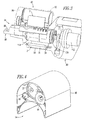
- the back-pack power supply module 82 includes a housing 92 having an opening 94 therethrough as best shown with upper housing portion 96 of Figure 4.
- the housing opening 94 receives the elongated line conductor 86 which passes through that opening (as best shown in Figure 3).
- the power supply circuit 2 is housed by the upper housing portion 96 and by lower housing portion 98 ( Figure 3). As was discussed above in connection with Figure 1, the power supply circuit 2 inputs the medium voltage 88 and outputs one or more DC voltages 100,102.
- the upper and lower housing portions 96,98 are separated by the housing opening 94.
- the capacitors 34,36 which are electrically connected in series, are embedded in a suitable high voltage electrical insulation 107 and are located separately within the lower housing portion 98, in order to prevent breakdown to other components of the power supply circuit 2 within the upper housing portion 96.
- the elongated line conductor 86 includes a first or lower (with respect to Figure 5) side and an opposite or upper (with respect to Figure 5) second side.
- the capacitors 34,36 are located on the first or lower side of the elongated line conductor 86, and the power supply circuit 2, except for those two capacitors 34,36, is substantially located on the opposite second or upper side of the elongated line conductor 86.
- Figure 5 shows a simplified view of the back-pack power supply module 82 including various electrical connections to the circuit breaker 80.
- the primary power and control electrical connections are shown, although a wide range of wiring layouts and routings may be employed for the same or other component locations.
- Suitable insulation (not shown) and spacing (not shown) are employed between the electrical conductors, in order to avoid potential breakdown to the medium voltage conductors of the circuit breaker 80.
- the circuit breaker 80 includes an operating mechanism 104 having a trip unit 106 and a motor actuator 108, which includes the closing coil 40 and the opening coil 42 of Figure 1.
- the first direct current output 26 ( Figure 1) selectively energizes the closing coil 40 and the second direct current output 32 selectively energizes the opening coil 42.
- a suitable module 110 combines a voltage sensor, a current sensor and a parasitic power supply for the trip unit 106.
- the motor actuator 108 drives a contact spring 112 (as shown within a suitable insulator 113) and a vacuum switch 114.
- a manual/emergency release mechanism 116 independently drives the contact spring 112 and vacuum switch 114.
- Three power conductors 118 are electrically connected between the motor actuator 108 (closing coil 40 and opening coil 42) and the power supply circuit 2.
- Two control conductors 120 from the trip unit 106 provide the control signals 57,61 to the FET gates 56,60, in order to control the closing coil 40 and the opening coil 42.
- a conductor 122 electrically connects the capacitive divider voltage input 6 ( Figure 1) and the capacitor 34 to the elongated line conductor 86.
- Another conductor 124 electrically connects the capacitive divider ground input 10 ( Figure 1) and the capacitor 38, the MOV 62 and the rectifier 16 to an external ground reference.
- Three conductor pairs 126 (or three conductors and one or more suitable ground conductors) provide sensed voltage, sensed current, power and ground signals from the module 110 to the trip unit 106.
- the vacuum switch 114 comprises a vacuum envelope 128 containing a fixed contact assembly 130 and a movable contact assembly 132 movable between a closed circuit position in electrical communication with the fixed contact assembly 130 (as shown in hidden line drawing in Figure 5) and an open circuit position (not shown) spaced apart from the fixed contact assembly 130, which is electrically interconnected with the elongated line conductor 86.
- the vacuum switch 114 is, for example, a conventional vacuum interrupter (VI) (e.g., without limitation, a 3" VI bottle made by Eaton
- the operating mechanism motor actuator 108 moves the movable contact assembly 132 between the closed circuit position and the open circuit position.
- a suitable shunt (e.g., a flexible conductor 134; a suitable conductive pivot, such as a double clinch joint) electrically connects the movable contact assembly 132 with the load conductor 90.
- An elongated housing 136 ( Figure 2) encloses the operating mechanism 104, the contact spring 112 and the flexible conductor 134. As shown in Figure 3, the vacuum switch 114 and the elongated line conductor 86 are received by the opening 94 of the back-pack module housing 92.
- trip unit 106 may employ a combination of one or more of analog, digital and/or processor-based circuits.
- the back-pack power supply module 82 and power supply circuit 2 provide power for the actuator 108 of the medium voltage circuit breaker 80 without requiring a separate power supply and power control wiring to the circuit breaker 80.
- the circuit breaker 80 may readily be installed by suitably electrically connecting the line and load terminals 86,90 to corresponding line and load cables (or power busses) (not shown).
- the parasitic back-pack power supply module 82 and power supply circuit 2 may be incorporated with the circuit breaker 80 by electrically connecting input terminals 6,10 to the elongated line conductor 86 and to an external ground reference (not shown).
- the power supply module 82 may output the AC voltage (V2) 14 to a suitable voltage monitor or sensor (not shown).
Landscapes
- Physics & Mathematics (AREA)
- Electromagnetism (AREA)
- Direct Current Feeding And Distribution (AREA)
- Gas-Insulated Switchgears (AREA)
Applications Claiming Priority (1)
| Application Number | Priority Date | Filing Date | Title |
|---|---|---|---|
| US11/127,564 US7280338B2 (en) | 2005-05-12 | 2005-05-12 | Power supply circuit, back-pack power supply module and circuit interrupter including the same |
Publications (1)
| Publication Number | Publication Date |
|---|---|
| EP1732097A2 true EP1732097A2 (fr) | 2006-12-13 |
Family
ID=37120853
Family Applications (1)
| Application Number | Title | Priority Date | Filing Date |
|---|---|---|---|
| EP06009869A Withdrawn EP1732097A2 (fr) | 2005-05-12 | 2006-05-12 | Circuit de source d'énergie avec circuit d'interruption |
Country Status (2)
| Country | Link |
|---|---|
| US (1) | US7280338B2 (fr) |
| EP (1) | EP1732097A2 (fr) |
Cited By (2)
| Publication number | Priority date | Publication date | Assignee | Title |
|---|---|---|---|---|
| EP3196912A4 (fr) * | 2014-09-18 | 2018-05-02 | Mitsubishi Electric Corporation | Commutateur |
| WO2023020750A1 (fr) * | 2021-08-16 | 2023-02-23 | Siemens Aktiengesellschaft | Agencement de commutateur et procédé de fonctionnement d'un agencement de commutateur |
Families Citing this family (11)
| Publication number | Priority date | Publication date | Assignee | Title |
|---|---|---|---|---|
| KR101197807B1 (ko) * | 2008-03-26 | 2012-11-05 | 엔페이즈 에너지, 인코포레이티드 | Ac 전압을 계측하는 방법 및 장치 |
| US8163574B2 (en) * | 2009-05-08 | 2012-04-24 | Eaton Corporaton | System and method for sensing voltage in medium-to-high voltage applications |
| US8487606B2 (en) | 2010-10-26 | 2013-07-16 | Eaton Corporation | Sensor assembly, trip unit including the same, and method of manufacturing a sensor assembly |
| US9088209B2 (en) | 2011-05-17 | 2015-07-21 | Eaton Corporation | Parasitic power supply and sensor apparatus including a power supply |
| AU2016235070A1 (en) | 2015-03-25 | 2017-07-20 | Sunpower Corporation | Converter topologies for common mode voltage reduction |
| US9954462B2 (en) | 2016-06-30 | 2018-04-24 | Sunpower Corporation | Converter topologies and control |
| WO2019043591A1 (fr) * | 2017-08-29 | 2019-03-07 | Eaton Intelligent Power Limited | Dispositif de commande de moteur à disjoncteur à semi-conducteur |
| US20230378744A1 (en) * | 2017-08-29 | 2023-11-23 | Eaton Intelligent Power Limited | Motor control device with solid state circuit breaker |
| CN111033924A (zh) * | 2017-08-29 | 2020-04-17 | 伊顿智能动力有限公司 | 具有固态断路器的矩阵转换器 |
| NZ787706A (en) * | 2019-12-05 | 2023-04-28 | S & C Electric Co | Low energy reclosing pulse test system and method |
| US12170178B2 (en) * | 2022-10-28 | 2024-12-17 | Eaton Intelligent Power Limited | Dual conductor Thomson coil for faster opening of a hybrid circuit breaker |
Family Cites Families (9)
| Publication number | Priority date | Publication date | Assignee | Title |
|---|---|---|---|---|
| US4188002A (en) * | 1978-10-23 | 1980-02-12 | Westinghouse Air Brake Company | Vital power varistor circuit for railroad signaling systems |
| US5384712A (en) | 1991-08-15 | 1995-01-24 | Eaton Corporation | Energy monitoring system for a plurality of local stations with snapshot polling from a central station |
| US5644463A (en) * | 1992-10-20 | 1997-07-01 | University Of Washington | Adaptive sequential controller with minimum switching energy |
| GB2286725A (en) * | 1994-02-18 | 1995-08-23 | Brian Mckean | Sequential isolating circuit breaker |
| US5585611A (en) * | 1994-03-31 | 1996-12-17 | Abb Power T&D Company Inc. | Interrupter assembly |
| US5548523A (en) | 1994-06-20 | 1996-08-20 | Eaton Corporation | Monitoring device secured to power distribution system conductors |
| US5550436A (en) * | 1994-09-01 | 1996-08-27 | International Rectifier Corporation | MOS gate driver integrated circuit for ballast circuits |
| US7239490B2 (en) | 2003-09-22 | 2007-07-03 | Eaton Corporation | Medium voltage vacuum circuit interrupter |
| US6930271B1 (en) * | 2004-08-13 | 2005-08-16 | Eaton Corporation | Circuit interrupter including linear actuator and manual pivot member |
-
2005
- 2005-05-12 US US11/127,564 patent/US7280338B2/en not_active Expired - Fee Related
-
2006
- 2006-05-12 EP EP06009869A patent/EP1732097A2/fr not_active Withdrawn
Cited By (2)
| Publication number | Priority date | Publication date | Assignee | Title |
|---|---|---|---|---|
| EP3196912A4 (fr) * | 2014-09-18 | 2018-05-02 | Mitsubishi Electric Corporation | Commutateur |
| WO2023020750A1 (fr) * | 2021-08-16 | 2023-02-23 | Siemens Aktiengesellschaft | Agencement de commutateur et procédé de fonctionnement d'un agencement de commutateur |
Also Published As
| Publication number | Publication date |
|---|---|
| US20060256470A1 (en) | 2006-11-16 |
| US7280338B2 (en) | 2007-10-09 |
Similar Documents
| Publication | Publication Date | Title |
|---|---|---|
| US6141192A (en) | Arcing fault protection system for a switchgear enclosure | |
| US7239490B2 (en) | Medium voltage vacuum circuit interrupter | |
| JP5002708B2 (ja) | 電流制限装置ベースのリセット可能memsマイクロスイッチアレイ | |
| EP1826791B1 (fr) | Interrupteur sous vide à trois positions fournissant l'interruption de courant, la déconnexion et la mise à la terre | |
| US7280338B2 (en) | Power supply circuit, back-pack power supply module and circuit interrupter including the same | |
| US20070253124A1 (en) | Circuit interrupter including point-on-wave controller and voltage sensors | |
| EP2088609A2 (fr) | Ensemble de conducteur d'unité de pôle encapsulé pour une unité de pôle encapsulé et interrupteur de circuit de tension moyenne l'incluant | |
| CN102420398B (zh) | 气体绝缘的中压开关设备 | |
| US20070252599A1 (en) | Circuit interrupter including manual selector selecting different point-on-wave switching characteristics | |
| US11637414B2 (en) | Three phase switchgear using single phase equipment in single casing | |
| US7986061B2 (en) | Electrical switching device | |
| US5204800A (en) | Voltage surge suppression device | |
| JP2024012680A (ja) | 送電 | |
| US7253630B1 (en) | Electro-optical voltage sensor circuit monitoring leakage or loss of vacuum of a vacuum interrupter and vacuum circuit interrupter including the same | |
| CN100541699C (zh) | 绝缘性能试验开关和对地漏电断路器 | |
| CA2310619C (fr) | Systeme de protection contre les arcs de rupture pour armoire electrique | |
| US20070035292A1 (en) | Vacuum circuit interrupter including circuit monitoring leakage or loss of vacuum and method of monitoring a vacuum interrupter for leakage or loss of vacuum | |
| CA3203844A1 (fr) | Appareil transformateur | |
| EP2249363A1 (fr) | Agencement, sous-station, procédé de fonctionnement et utilisation d'un commutateur de mise à la terre pour la protection d'un circuit électrique contre des défauts de court-circuit en ligne | |
| CZ283275B6 (cs) | Vícefázový spínací systém a uspořádání generátoru s takovýmto spínacím systémem | |
| US20260081433A1 (en) | Energy harvesting module | |
| US20250385507A1 (en) | Method of controlling an electrical protection device, associated device and installation | |
| EP4572053A1 (fr) | Disjoncteur et procédé de fonctionnement d'un réseau de distribution d'énergie doté d'un disjoncteur | |
| EP3906574B1 (fr) | Disjoncteur comportant un ensemble condensateur de tension de récupération transitoire interne | |
| SU1582255A1 (ru) | Устройство дл защиты от токов утечки в электрических сет х с вентильными преобразовател ми |
Legal Events
| Date | Code | Title | Description |
|---|---|---|---|
| PUAI | Public reference made under article 153(3) epc to a published international application that has entered the european phase |
Free format text: ORIGINAL CODE: 0009012 |
|
| AK | Designated contracting states |
Kind code of ref document: A2 Designated state(s): AT BE BG CH CY CZ DE DK EE ES FI FR GB GR HU IE IS IT LI LT LU LV MC NL PL PT RO SE SI SK TR |
|
| AX | Request for extension of the european patent |
Extension state: AL BA HR MK YU |
|
| STAA | Information on the status of an ep patent application or granted ep patent |
Free format text: STATUS: THE APPLICATION IS DEEMED TO BE WITHDRAWN |
|
| 18D | Application deemed to be withdrawn |
Effective date: 20131203 |