EP1734640B1 - Dispositif permettant de fixer un appareil électrique à un moteur électrique - Google Patents
Dispositif permettant de fixer un appareil électrique à un moteur électrique Download PDFInfo
- Publication number
- EP1734640B1 EP1734640B1 EP06011584.7A EP06011584A EP1734640B1 EP 1734640 B1 EP1734640 B1 EP 1734640B1 EP 06011584 A EP06011584 A EP 06011584A EP 1734640 B1 EP1734640 B1 EP 1734640B1
- Authority
- EP
- European Patent Office
- Prior art keywords
- electric motor
- projections
- assembly according
- elements
- holding elements
- Prior art date
- Legal status (The legal status is an assumption and is not a legal conclusion. Google has not performed a legal analysis and makes no representation as to the accuracy of the status listed.)
- Active
Links
Images


Classifications
-
- H—ELECTRICITY
- H02—GENERATION; CONVERSION OR DISTRIBUTION OF ELECTRIC POWER
- H02K—DYNAMO-ELECTRIC MACHINES
- H02K5/00—Casings; Enclosures; Supports
- H02K5/04—Casings or enclosures characterised by the shape, form or construction thereof
- H02K5/22—Auxiliary parts of casings not covered by groups H02K5/06-H02K5/20, e.g. shaped to form connection boxes or terminal boxes
- H02K5/225—Terminal boxes or connection arrangements
-
- H—ELECTRICITY
- H02—GENERATION; CONVERSION OR DISTRIBUTION OF ELECTRIC POWER
- H02K—DYNAMO-ELECTRIC MACHINES
- H02K11/00—Structural association of dynamo-electric machines with electric components or with devices for shielding, monitoring or protection
- H02K11/30—Structural association with control circuits or drive circuits
- H02K11/33—Drive circuits, e.g. power electronics
Definitions
- the invention relates to an electric motor assembly with a holding device for mounting an electronic device, in particular a frequency converter, on an air-cooled, provided with cooling fins electric motor, in particular standard motor, between the device and the electric motor connected to the device receiving element and a plurality, connected to the receiving element, arranged on the electric motor holding elements are arranged, which bridge the distance between the device and the electric motor, wherein the holding elements bear force-transmitting and / or in constructive clearances of the electric motor and the holding elements have laterally projecting projections and that when mounted holding elements, the projections are facing each other.
- Electric motors and also the standard motors, have different external configurations.
- adaptation structures are required to attach to such engines on a case by case basis or subsequently electronic devices such as frequency converters or other automation equipment.
- the product Hya-Drive known by the KSB brochure regulation: "Everything perfectly regulated: switching and control systems for all pumps", May 2003, pages 6-7 , on the one hand provides the attachment of a frequency converter in the axial extension of the electric motor housing via a special, the normal fan housing replacement adapter housing.
- the original motor fan housing is replaced by a special adapter housing during assembly.
- the use of fastening webs is provided with which the housing of the frequency converter is fixed by a plurality of screw on the electric motor.
- this requires a subsequent structural change to the electric motor, which certified Applications of an electric motor can be excluded. And it must be made a variety of special, depending on the size of completely different holding devices or stockpiled to achieve in a particular case, a quick adjustment.
- Disadvantages are in addition to the structural change to the motor housing and the additional manufacturing steps for drilling mounting holes.
- the attachment to the different types of different electric motors is difficult.
- an increased use of materials and tools is the result of the large range of services offered and the indispensable size of frames.
- a generic type of electric motor assembly according to the preamble of claim 1 is known from FR 2 756 676 A1 known.
- the invention is therefore based on the problem to develop a holding device that allows for an electric motor series with different sizes in a simple manner and without a change to the electric motor, the subsequent attachment of electronic devices.
- any, automation device such as a control or communication device, a diagnostic device or a Frequency converter easy to attach to a motor housing.
- a receiving element to which a device is attached By stocking of a receiving element to which a device is attached, and the combination of the receiving element with a plurality of holding elements, which abut forces on and / or in constructive free spaces of an electric motor, a subsequent or additional processing of the electric motor is no longer required.
- retaining elements are selected. The latter are hooked into a constructive motor space, for example between two cooling fins of an electric motor, and connected to the receiving element.
- a retaining device formed in this way is attached to the electric motor without its structural change. This is a basic prerequisite for special applications, such as use in a hazardous area. Compared to the conventional holding devices can be created with this solution at a lower material and tool insert a variety of combinations that allows for electronic devices whose attachment to various electric motors.
- Embodiments provide a frame or plate-shaped design of the receiving element.
- the plate-shaped receiving element may have grid-shaped openings of different shape for the implementation of fasteners.
- Such openings may be arranged in the manner of a hole pattern, which correspond to a mounting grid of various devices that are held with screws in the receiving element.
- the openings may be formed as round or oval openings or slots to achieve by the shape of a variety of mounting options.
- the holding elements can be connected to transmit forces with these openings.
- the projections engage positively in existing free spaces of the electric motor housing.
- the projections are arranged on both sides of the motor longitudinal axis. Thus, by simply hooking the projections between the cooling fins of an electric motor attachment to the same can be achieved.
- the projections can also be supported on existing free spaces of the electric motor limiting contours.
- the holding elements can embrace with the projections, for example, the engine cooling ribs and / or be supported with the projections on the engine cooling ribs.
- the projections may be an integral part of a holding element, or attached thereto as an additional part.
- the holding elements may also have a plurality of fastening openings, which allows attachment of the projections at different heights.
- the projections are formed as from the holding element laterally projecting strip elements, or pin or tooth elements or have a shape that produces a secure and force-transmitting connection. It is also possible to insert the projections from the axial direction in the spaces between the cooling fins.
- the fastening takes place by means of projections which are designed as clip elements.
- projections which are designed as clip elements.
- Such clasps on the engine cooling ribs which consist for example of steel, simplify the mounting of the holding elements to the electric motor considerably, as they are quickly and easily attached by means of a striking tool, such as a hammer on the cooling fins or other locations of the electric motor.
- the clamping forces act from the top and / or bottom to the limiting contours of the free spaces and thus support the positive fastening.
- pin-shaped projections engage in free spaces in the form of existing attachment openings of the motor housing and are held therein in a form-fitting manner.
- electric motors especially on standard motors, often several mounting levels are arranged on the outer sides, to If necessary, motor feet are screwed on. These planes may face each other or, in a coordinate system view, lie in two, three or four quadrants.
- the motor housings are provided with prefabricated threaded holes for receiving screw elements. Driven therein, pin-shaped projections ensure secure attachment of the holding elements and thus also the electronic device.
- the projections have barbs or tips. These claw into the existing free spaces of the electric motor limiting contours.
- the holding elements are arranged as a spacer between the receiving element and the electric motor, wherein engaging in existing fastening openings screw connect the receiving element with the electric motor.
- the screw elements are guided through suitable openings of the receiving element and screwed into the mounting holes for motor feet.
- the holding elements are formed in this case as the distance ensuring strips, projections, teeth, pins or as the screw surrounding tubular pieces, the spacers abutting forces between receiving element and electric motor.
- a universal mounting option is achieved by the configuration that the holding elements are arranged as a spacer between the receiving element and the electric motor, wherein at least one clamping fixture connects the receiving element with the electric motor.
- the clamping fixture consists of a clamping band and a clamping / connecting means.
- the spacers on recesses for performing the clamping band and the clamping fixture is guided around the electric motor. By tightening the clamping fixture, the holding elements are fixed to the electric motor pulled and an electronic device is easily and safely attached to the electric motor.
- the vibration properties of the holding device are improved.
- damping means are arranged between the holding elements and / or the clamping fixture and the electric motor.
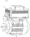
- Fig. 1 shows a mounted electric motor unit.
- an electronic device here a frequency converter, with a - here frame-shaped - receiving element 2 and several, here two holding elements 3, 4, attached to a designed as a standard motor electric motor 5.
- the holding elements 3, 4 have projections 6 formed as pin elements.
- the holding elements 3, 4 are connected to the receiving element 2 by means known per se, these may be screws, rivets, pins, welded joints or the like.
- the electric motor 5 has four surfaces 7, which lie in a mounting plane. This attachment level is perpendicular to the plane of the motor feet 8. An analogous arrangement of the surfaces 7 is located on the opposite, not visible here motor side. Due to the total here three attachment levels, it is possible to attach by appropriate arrangement of the motor feet 8, the electric motor 5 in three different installation levels.
- the surfaces 7 have factory fastening openings 9, usually threaded blind holes, which serve to receive screws with which the motor feet 8 are selectively attached.
- the mounting holes 9 are also constructive clearances 13 when not in use.
- the pin-shaped projections 6 of the holding elements 3, 4 are held by engagement in these free spaces or mounting holes by engagement. Thus, a secure attachment of the frequency converter 1 is achieved.
- Fig. 2 shows a holding device, in contrast to Fig. 1 the holding elements 3, 4 are provided with strip-shaped projections 10, 11.
- the projections 10, 11 designed as individual parts are wedge-shaped. They are connected by means known per se with the holding elements 3, 4. As well they can be designed in one piece with the holding elements.
- the cooling fins 12 have the usual free spaces 13 in electric motors.
- the projections 10, 11 of the holding elements 3, 4 are inserted during assembly from the axial direction.
- the projections 10, 11 engage in the free spaces 13 or surround the cooling ribs 12 and thereby hold the holding elements 3, 4 positively on the motor housing. This positive connection saves the conventional, installation-consuming types of fastening.
- Such holding elements 3, 4, which are designed for example for a size with predetermined outer diameters and have a predetermined distance between the projections, can be mounted at larger housing diameters in the region of cooling fins 12, which are above a larger housing diameter are arranged.
- a holding device for different electric motor sizes is applicable.
- Fig. 3 shows another holding device, in which between a - here plate-shaped - receiving element 2 and the electric motor 5, the holding elements are designed as spacers 14.
- the electric motor 5 is rotated by 90 °.
- the motor feet 8 became according to Fig. 1 also fastened in a 90 ° rotated arrangement.
- the terminal box 15 comes from an upper position according to Fig. 1 and Fig. 2 to be in a lateral arrangement.
- the holding elements 14 can be supported both between the cooling fins 12 in the free spaces 13, on the cooling fins 12 and on the surfaces 7.
- the holding elements 14 are formed as pipe sections which - not shown here - surround mounting screws. Such screws are screwed into the mounting holes 9 of the surfaces 7 and connect the receiving element 2 and / or the frequency converter 1 to the electric motor. 5
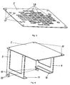
- Fig. 4 shows a frame-shaped receiving element 2 with openings 16 for connection to holding elements.
- the receiving element 2 has four other openings 17 for mounting an electronic device, such as a frequency converter on.
- Fig. 5 shows a plate-shaped receiving element 2 with a plurality of round openings 17 and slots 18 for the passage of fasteners.
- Fig. 6 shows a modification of a holding device according to Fig. 2 with plate-shaped receiving element 2 and holding elements 3, 4.
- the holding elements 3, 4 are formed as laterally projecting and facing each other, strip-shaped projections 11, 10.
- the holding elements 3, 4 securing tabs 19 with openings 20. Through the opening 20 passed fasteners in Form of self-tapping screws engage in other existing mounting holes 9 of the motor housing in order to achieve additional securing of the holding elements 3, 4 on the electric motor 5.
- Fig. 7 shows holding elements 3, 4 with laterally projecting tooth elements 21 as projections. These can be made by material recesses from the in Fig. 6 shown strip-shaped projections 10, 11 may be generated.
- Fig. 7 shows various arrangements of openings 20 for securing purposes.
- Fig. 8 shows a variant of a holding element 3 with pin elements formed as 6 projections.
- Fig. 9 shows a trained as a tubular spacer retaining element 14th
- Fig. 10 shows a mounted electric motor unit.
- an electronic device 1 with a - here frame-shaped - receiving element 2 and several, here two holding elements 3, 4, attached to a designed as a standard motor electric motor 5.
- the holding elements 3, 4 have projections 22 formed as clip elements.
- the holding elements 3, 4 are connected to the receiving element 2 by means known per se, these may be screws, rivets, pins, welded joints or the like.
- the projections 22 are connected by means known per se with the holding elements 3, 4. As well they can be designed in one piece with the holding elements 3, 4.
- the cooling fins 12 have the usual free spaces 13 in electric motors.
- the projections 22 rest on the cooling fins 12 as limiting contours of the free spaces.
- the brackets can be hit or pushed onto the engine cooling fins 12 with a hammer or other impact tool.
- the projections 22 surround the cooling ribs 12 and thereby hold the holding elements 3, 4 positively on the motor housing. This positive connection saves the conventional, installation-consuming types of fastening.
- the clamping forces act from the top and / or bottom to the limiting contours of the free spaces and support the positive fastening.
- Such holding elements 3, 4, which are designed for example for a size with predetermined outer diameters and a predetermined distance between the Projections can be mounted at larger housing diameters in the range of cooling fins 12, which are arranged above a larger housing diameter.
- a holding device for different electric motor sizes is applicable.
- Fig. 11 shows another holding device.
- the receiving element is formed here only by two edge strips 23 and 24, resulting in a saving of material.
- the holding elements 3, 4 have a plurality of attachment openings 25, which allows attachment of mutually facing projections in the form of clip elements 26 at different heights.
- the clip elements 26 have barbs 27.
- the clip elements 26 may be provided with cutouts. The resulting peaks or barbs clinging during assembly of the holding elements 3, 4 fixed in the existing free spaces 13 of the electric motor limiting contours, for example, in the engine cooling fins. As a result, an additional securing of the holding elements 3, 4 on the electric motor 5 is achieved.
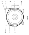
- Fig. 12 and Fig. 13 show a further mounted holding device to an electric motor 5.
- a receiving element 2 and holding elements 3, 4 are fixed to the electric motor 5.
- the holding elements 3, 4 are designed in one piece with the receiving element 2 and have strip-shaped projections 11, 10.
- the holding elements are by means of two clamping fasteners, consisting of the electric motor 5 guided clamping bands 28, 29 and tensioning / connecting means 30, 31 lashed to the electric motor 5.
- the holding elements 3, 4 are used in the arrangement shown as a spacer. They have recesses 32 for performing the tension bands 28, 29. Straps are available in different designs and sizes. Preferably, steel clamps with jaw or worm thread can be used.
- damping means for example made of hard rubber, can be arranged.
Landscapes
- Engineering & Computer Science (AREA)
- Power Engineering (AREA)
- Microelectronics & Electronic Packaging (AREA)
- Motor Or Generator Frames (AREA)
- Motor Or Generator Cooling System (AREA)
Claims (12)
- Ensemble de moteur électrique comprenant un dispositif de retenue pour la fixation d'un appareil électronique, en particulier d'un convertisseur de fréquence, sur un moteur électrique refroidi par air et pourvu d'ailettes de refroidissement, en particulier un moteur de dimensions normales, un élément de réception (2) relié à l'appareil (1) et plusieurs éléments de retenue (3, 4, 14) s'appliquant contre le moteur électrique (5) et reliés à l'élément de réception (2) étant disposés entre l'appareil et le moteur électrique, lesquels éléments de retenue enjambent la distance entre l'appareil (1) et le moteur électrique (5), les éléments de retenue (3, 4, 14) s'appliquant contre et/ou dans des espaces libres de construction (9, 13) du moteur électrique (5) de manière à transmettre des forces, et les éléments de retenue (3, 4) comprenant des saillies latéralement protubérantes (6, 10, 11, 21, 22, 26), et les saillies (6, 10, 11, 21, 22, 26) étant tournées les unes vers les autres lorsque les éléments de retenue (3, 4) sont montés, caractérisé en ce que les saillies (6, 10, 11, 21, 22, 26) s'appliquent contre les ailettes de refroidissement (12) en tant que contours de délimitation des espaces libres (13), ou les saillies (6) réalisées sous forme d'éléments formant goupille sont maintenues par engagement par complémentarité de formes dans des espaces libres réalisés dans des surfaces (7) en tant que trous borgnes filetés (9).
- Ensemble de moteur électrique selon la revendication 1, caractérisé en ce que l'élément de réception (2) est réalisé en forme de cadre ou en forme de plaque.
- Ensemble de moteur électrique selon la revendication 1 ou 2, caractérisé en ce que l'élément de réception en forme de plaque (2) comprend des ouvertures (17, 18), disposées en forme de grille, de formes différentes pour le passage d'éléments de fixation.
- Ensemble de moteur électrique selon la revendication 1, caractérisé en ce que les saillies (6, 10, 11, 21) s'engagent par complémentarité de formes dans des espaces libres existants (9, 13) du moteur électrique (5).
- Ensemble de moteur électrique selon la revendication 1 ou 4, caractérisé en ce que les saillies (6, 10, 11, 21, 22, 26) s'appuient sur des contours délimitant les espaces libres du moteur électrique.
- Ensemble de moteur électrique selon la revendication 4 ou 5, caractérisé en ce que les saillies (6, 10, 11, 21, 22, 26) sont réalisées sous forme d'éléments formant baguette (10, 11).
- Ensemble de moteur électrique selon la revendication 4 ou 5, caractérisé en ce que les saillies (6, 10, 11, 21, 22, 26) sont réalisées sous forme d'un ou de plusieurs éléments formant goupille (6) ou dent (21).
- Ensemble de moteur électrique selon la revendication 4 ou 5, caractérisé en ce que les saillies (6, 10, 11, 21, 22, 26) sont réalisées sous forme d'éléments formant pince (22, 26).
- Ensemble de moteur électrique selon l'une quelconque des revendications 4 à 8, caractérisé en ce que les éléments de retenue (3, 4) pourvus des saillies (6, 10, 11, 21) s'engagent dans des espaces libres (13) entre des ailettes de refroidissement de moteur (12).
- Ensemble de moteur électrique selon la revendication 9, caractérisé en ce que les saillies (6, 10, 11, 21) sont insérées à partir de la direction axiale dans des espaces libres (13) entre les ailettes de refroidissement de moteur (12).
- Ensemble de moteur électrique selon l'une quelconque des revendications 1 à 10, caractérisé en ce que des vis autotaraudeuses s'engageant dans des ouvertures de fixation (9) du moteur électrique (5) fixent les éléments de retenue (3, 4j et/ou des pattes de fixation (19).
- Ensemble de moteur électrique selon l'une quelconque des revendications 1 à 11, caractérisé en ce que les saillies (6, 10, 11, 21, 22, 26) comprennent des crochets (27) ou des pointes.
Priority Applications (1)
| Application Number | Priority Date | Filing Date | Title |
|---|---|---|---|
| PL06011584T PL1734640T3 (pl) | 2005-06-17 | 2006-06-03 | Urządzenie do przytrzymywania urządzenia elektronicznego na silniku elektrycznym |
Applications Claiming Priority (2)
| Application Number | Priority Date | Filing Date | Title |
|---|---|---|---|
| DE102005028426 | 2005-06-17 | ||
| DE102006023050A DE102006023050A1 (de) | 2005-06-17 | 2006-05-17 | Haltevorrichtung für elektronisches Gerät |
Publications (3)
| Publication Number | Publication Date |
|---|---|
| EP1734640A2 EP1734640A2 (fr) | 2006-12-20 |
| EP1734640A3 EP1734640A3 (fr) | 2011-02-23 |
| EP1734640B1 true EP1734640B1 (fr) | 2015-01-07 |
Family
ID=36942629
Family Applications (1)
| Application Number | Title | Priority Date | Filing Date |
|---|---|---|---|
| EP06011584.7A Active EP1734640B1 (fr) | 2005-06-17 | 2006-06-03 | Dispositif permettant de fixer un appareil électrique à un moteur électrique |
Country Status (6)
| Country | Link |
|---|---|
| EP (1) | EP1734640B1 (fr) |
| DE (1) | DE102006023050A1 (fr) |
| DK (1) | DK1734640T3 (fr) |
| ES (1) | ES2533456T3 (fr) |
| PL (1) | PL1734640T3 (fr) |
| PT (1) | PT1734640E (fr) |
Families Citing this family (9)
| Publication number | Priority date | Publication date | Assignee | Title |
|---|---|---|---|---|
| DE102007012351A1 (de) * | 2007-03-14 | 2008-09-18 | Leukhardt Schaltanlagen Gmbh | Kombination aus einer elektrischen Maschine und einem Schaltelement dafür |
| DE102007046662A1 (de) * | 2007-09-27 | 2009-04-02 | Ksb Aktiengesellschaft | Geräteanordnung für eine Kreiselpumpenanordnung |
| DE102007046674A1 (de) | 2007-09-27 | 2009-04-09 | Ksb Aktiengesellschaft | Haltevorrichtung für eine Kreiselpumpenanordnung |
| WO2011117829A2 (fr) * | 2010-03-23 | 2011-09-29 | Refcomp S.P.A. | Ensemble onduleur destiné à des compresseurs et compresseurs comprenant ledit ensemble |
| JP5722644B2 (ja) * | 2011-01-27 | 2015-05-27 | 株式会社日立産機システム | 回転電機 |
| DE102013205897B4 (de) * | 2013-04-03 | 2022-11-10 | Lenze Se | Antriebssystem |
| DE102014209975A1 (de) | 2014-05-26 | 2015-11-26 | Ksb Aktiengesellschaft | Motoradapter |
| DE102019215842A1 (de) * | 2019-10-15 | 2021-04-15 | Baumüller Nürnberg GmbH | Antrieb |
| EP3817203B1 (fr) | 2019-10-29 | 2021-09-08 | Wilo Se | Fixation détachable d'un convertisseur de fréquence sur un moteur électrique |
Family Cites Families (7)
| Publication number | Priority date | Publication date | Assignee | Title |
|---|---|---|---|---|
| US2003031A (en) * | 1933-06-21 | 1935-05-28 | Westinghouse Electric & Mfg Co | Capacitor motor |
| DE2414664A1 (de) * | 1974-03-27 | 1975-10-02 | Rau Swf Autozubehoer | Antriebseinheit fuer ein haushaltgeraet, insbesondere einen haushalt-abfallverdichter |
| FR2517129A1 (fr) * | 1981-11-26 | 1983-05-27 | Ducellier & Cie | Connecteur |
| DE3602606A1 (de) * | 1986-01-17 | 1987-07-23 | Hanning Elektro Werke | Waschautomatenantrieb mit einem ueber einen umrichter gespeisten drehstrommotor |
| DE3823350A1 (de) * | 1988-07-09 | 1990-01-18 | Heidolph Elektro Gmbh & Co Kg | Elektromotor |
| FR2756676A1 (fr) * | 1996-12-03 | 1998-06-05 | Centor | Moteur a vitesse variable et carcasse pour un tel moteur |
| ES2226090T3 (es) * | 1997-11-18 | 2005-03-16 | Atb Austria Antriebstechnik Aktiengesellschaft | Carcasa de estator para electromotores. |
-
2006
- 2006-05-17 DE DE102006023050A patent/DE102006023050A1/de not_active Withdrawn
- 2006-06-03 PL PL06011584T patent/PL1734640T3/pl unknown
- 2006-06-03 DK DK06011584T patent/DK1734640T3/da active
- 2006-06-03 PT PT60115847T patent/PT1734640E/pt unknown
- 2006-06-03 EP EP06011584.7A patent/EP1734640B1/fr active Active
- 2006-06-03 ES ES06011584.7T patent/ES2533456T3/es active Active
Also Published As
| Publication number | Publication date |
|---|---|
| ES2533456T3 (es) | 2015-04-10 |
| DK1734640T3 (da) | 2015-03-30 |
| PT1734640E (pt) | 2015-04-27 |
| EP1734640A3 (fr) | 2011-02-23 |
| PL1734640T3 (pl) | 2015-06-30 |
| DE102006023050A1 (de) | 2006-12-28 |
| EP1734640A2 (fr) | 2006-12-20 |
Similar Documents
| Publication | Publication Date | Title |
|---|---|---|
| DE202015105009U1 (de) | Frontplattenanordung eines Leistungsgeräts | |
| EP1734640B1 (fr) | Dispositif permettant de fixer un appareil électrique à un moteur électrique | |
| DE202010013008U1 (de) | Spannvorrichtung eines Antriebswerkzeugs | |
| DE102010028084B4 (de) | Elastisches Lager zur Aufhängung einer Abgasanlage mit einer einfach zu montierenden Grundplatte | |
| DE102012013884A1 (de) | Befestigungsanordnung einer Abgas führenden Anbaueinrichtung | |
| EP2546615A2 (fr) | Dispositif de fixation pour un composant dýun véhicule automobile | |
| DE202009001797U1 (de) | Werkzeughalterung für Elektrohandwerkzeuggeräte | |
| EP1621781B1 (fr) | Dispositif de fixation pour profilé | |
| EP3763572A1 (fr) | Dispositif de maintien d'une plaque d'immatriculation de véhicule automobile | |
| EP2590493A2 (fr) | Convertisseur de fréquence | |
| EP3402993B1 (fr) | Systeme de montage dote de rail de montage et ecrou de retenue en saillie | |
| DE102008035396B4 (de) | Haltevorrichtung für ein Heiz- oder Lüftungsgerät | |
| DE202021102165U1 (de) | System zur Befestigung | |
| EP3431777B1 (fr) | Fixation d'une barre de fixation pour une grille de protection de ventilateur | |
| DE102007052961A1 (de) | Gehäuse zur Aufnahme eines Bauteils, insbesondere zur Aufnahme eines Steuergerätes für einen Fahrzeugsitz | |
| DE102015200660A1 (de) | Ladeeinrichtung | |
| EP3431772B1 (fr) | Fixation d'une barre de fixation pour une grille de protection de ventilateur | |
| DE102009013975A1 (de) | Kupplungsgeberzylinder | |
| EP3431774B1 (fr) | Fixation d'une barre de fixation pour une grille de protection de ventilateur | |
| DE202006006688U1 (de) | Befestigung mit Verlierschutz für ein Befestigungsmittel | |
| DE102015012498A1 (de) | Kettentrieb-Baugruppe mit Spannschienen-Montagehilfe | |
| DE102014218545A1 (de) | Vorrichtung zur Unverlierbarkeit von Schrauben | |
| DE102017114129A1 (de) | Montageplattenanordnung für den Innenausbau eines Schaltschranks und ein entsprechender Schaltschrank | |
| DE202013102509U1 (de) | Konstruktionsprofilkabelkanalbefestigungsvorrichtung | |
| EP3937599A1 (fr) | Logement et procédé de montage d'un logement |
Legal Events
| Date | Code | Title | Description |
|---|---|---|---|
| PUAI | Public reference made under article 153(3) epc to a published international application that has entered the european phase |
Free format text: ORIGINAL CODE: 0009012 |
|
| AK | Designated contracting states |
Kind code of ref document: A2 Designated state(s): AT BE BG CH CY CZ DE DK EE ES FI FR GB GR HU IE IS IT LI LT LU LV MC NL PL PT RO SE SI SK TR |
|
| AX | Request for extension of the european patent |
Extension state: AL BA HR MK YU |
|
| PUAL | Search report despatched |
Free format text: ORIGINAL CODE: 0009013 |
|
| AK | Designated contracting states |
Kind code of ref document: A3 Designated state(s): AT BE BG CH CY CZ DE DK EE ES FI FR GB GR HU IE IS IT LI LT LU LV MC NL PL PT RO SE SI SK TR |
|
| AX | Request for extension of the european patent |
Extension state: AL BA HR MK YU |
|
| 17P | Request for examination filed |
Effective date: 20110823 |
|
| AKX | Designation fees paid |
Designated state(s): AT BE BG CH CY CZ DE DK EE ES FI FR GB GR HU IE IS IT LI LT LU LV MC NL PL PT RO SE SI SK TR |
|
| 17Q | First examination report despatched |
Effective date: 20120823 |
|
| GRAP | Despatch of communication of intention to grant a patent |
Free format text: ORIGINAL CODE: EPIDOSNIGR1 |
|
| INTG | Intention to grant announced |
Effective date: 20140922 |
|
| RIN1 | Information on inventor provided before grant (corrected) |
Inventor name: SCHUHMACHER, VOLKER Inventor name: GONTERMANN, DANIEL Inventor name: KOEHLER, BERND Inventor name: KRELLNER, MARKUS Inventor name: GROENING, NORBERT Inventor name: HEBEL, NORBERT |
|
| GRAS | Grant fee paid |
Free format text: ORIGINAL CODE: EPIDOSNIGR3 |
|
| GRAA | (expected) grant |
Free format text: ORIGINAL CODE: 0009210 |
|
| AK | Designated contracting states |
Kind code of ref document: B1 Designated state(s): AT BE BG CH CY CZ DE DK EE ES FI FR GB GR HU IE IS IT LI LT LU LV MC NL PL PT RO SE SI SK TR |
|
| REG | Reference to a national code |
Ref country code: GB Ref legal event code: FG4D Free format text: NOT ENGLISH |
|
| REG | Reference to a national code |
Ref country code: CH Ref legal event code: EP |
|
| REG | Reference to a national code |
Ref country code: DE Ref legal event code: R081 Ref document number: 502006014144 Country of ref document: DE Owner name: KSB SE & CO. KGAA, DE Free format text: FORMER OWNER: KSB AG, 67227 FRANKENTHAL, DE |
|
| REG | Reference to a national code |
Ref country code: IE Ref legal event code: FG4D Free format text: LANGUAGE OF EP DOCUMENT: GERMAN |
|
| REG | Reference to a national code |
Ref country code: AT Ref legal event code: REF Ref document number: 706321 Country of ref document: AT Kind code of ref document: T Effective date: 20150215 |
|
| REG | Reference to a national code |
Ref country code: DE Ref legal event code: R096 Ref document number: 502006014144 Country of ref document: DE Effective date: 20150226 |
|
| REG | Reference to a national code |
Ref country code: DK Ref legal event code: T3 Effective date: 20150326 |
|
| REG | Reference to a national code |
Ref country code: ES Ref legal event code: FG2A Ref document number: 2533456 Country of ref document: ES Kind code of ref document: T3 Effective date: 20150410 |
|
| REG | Reference to a national code |
Ref country code: NL Ref legal event code: T3 |
|
| REG | Reference to a national code |
Ref country code: SE Ref legal event code: TRGR |
|
| REG | Reference to a national code |
Ref country code: NL Ref legal event code: T3 |
|
| REG | Reference to a national code |
Ref country code: PT Ref legal event code: SC4A Free format text: AVAILABILITY OF NATIONAL TRANSLATION Effective date: 20150402 |
|
| REG | Reference to a national code |
Ref country code: NL Ref legal event code: T3 |
|
| REG | Reference to a national code |
Ref country code: GR Ref legal event code: EP Ref document number: 20150400688 Country of ref document: GR Effective date: 20150421 |
|
| REG | Reference to a national code |
Ref country code: FR Ref legal event code: PLFP Year of fee payment: 10 |
|
| REG | Reference to a national code |
Ref country code: LT Ref legal event code: MG4D |
|
| REG | Reference to a national code |
Ref country code: PL Ref legal event code: T3 |
|
| REG | Reference to a national code |
Ref country code: SK Ref legal event code: T3 Ref document number: E 18385 Country of ref document: SK |
|
| PG25 | Lapsed in a contracting state [announced via postgrant information from national office to epo] |
Ref country code: BG Free format text: LAPSE BECAUSE OF FAILURE TO SUBMIT A TRANSLATION OF THE DESCRIPTION OR TO PAY THE FEE WITHIN THE PRESCRIBED TIME-LIMIT Effective date: 20150407 Ref country code: LT Free format text: LAPSE BECAUSE OF FAILURE TO SUBMIT A TRANSLATION OF THE DESCRIPTION OR TO PAY THE FEE WITHIN THE PRESCRIBED TIME-LIMIT Effective date: 20150107 |
|
| PG25 | Lapsed in a contracting state [announced via postgrant information from national office to epo] |
Ref country code: IS Free format text: LAPSE BECAUSE OF FAILURE TO SUBMIT A TRANSLATION OF THE DESCRIPTION OR TO PAY THE FEE WITHIN THE PRESCRIBED TIME-LIMIT Effective date: 20150507 Ref country code: LV Free format text: LAPSE BECAUSE OF FAILURE TO SUBMIT A TRANSLATION OF THE DESCRIPTION OR TO PAY THE FEE WITHIN THE PRESCRIBED TIME-LIMIT Effective date: 20150107 |
|
| REG | Reference to a national code |
Ref country code: DE Ref legal event code: R097 Ref document number: 502006014144 Country of ref document: DE |
|
| PG25 | Lapsed in a contracting state [announced via postgrant information from national office to epo] |
Ref country code: RO Free format text: LAPSE BECAUSE OF FAILURE TO SUBMIT A TRANSLATION OF THE DESCRIPTION OR TO PAY THE FEE WITHIN THE PRESCRIBED TIME-LIMIT Effective date: 20150107 Ref country code: EE Free format text: LAPSE BECAUSE OF FAILURE TO SUBMIT A TRANSLATION OF THE DESCRIPTION OR TO PAY THE FEE WITHIN THE PRESCRIBED TIME-LIMIT Effective date: 20150107 |
|
| PLBE | No opposition filed within time limit |
Free format text: ORIGINAL CODE: 0009261 |
|
| STAA | Information on the status of an ep patent application or granted ep patent |
Free format text: STATUS: NO OPPOSITION FILED WITHIN TIME LIMIT |
|
| 26N | No opposition filed |
Effective date: 20151008 |
|
| PG25 | Lapsed in a contracting state [announced via postgrant information from national office to epo] |
Ref country code: MC Free format text: LAPSE BECAUSE OF FAILURE TO SUBMIT A TRANSLATION OF THE DESCRIPTION OR TO PAY THE FEE WITHIN THE PRESCRIBED TIME-LIMIT Effective date: 20150107 |
|
| PG25 | Lapsed in a contracting state [announced via postgrant information from national office to epo] |
Ref country code: SI Free format text: LAPSE BECAUSE OF FAILURE TO SUBMIT A TRANSLATION OF THE DESCRIPTION OR TO PAY THE FEE WITHIN THE PRESCRIBED TIME-LIMIT Effective date: 20150107 Ref country code: LU Free format text: LAPSE BECAUSE OF FAILURE TO SUBMIT A TRANSLATION OF THE DESCRIPTION OR TO PAY THE FEE WITHIN THE PRESCRIBED TIME-LIMIT Effective date: 20150603 |
|
| REG | Reference to a national code |
Ref country code: IE Ref legal event code: MM4A |
|
| PG25 | Lapsed in a contracting state [announced via postgrant information from national office to epo] |
Ref country code: IE Free format text: LAPSE BECAUSE OF NON-PAYMENT OF DUE FEES Effective date: 20150603 |
|
| REG | Reference to a national code |
Ref country code: FR Ref legal event code: PLFP Year of fee payment: 11 |
|
| PG25 | Lapsed in a contracting state [announced via postgrant information from national office to epo] |
Ref country code: HU Free format text: LAPSE BECAUSE OF FAILURE TO SUBMIT A TRANSLATION OF THE DESCRIPTION OR TO PAY THE FEE WITHIN THE PRESCRIBED TIME-LIMIT; INVALID AB INITIO Effective date: 20060603 |
|
| REG | Reference to a national code |
Ref country code: FR Ref legal event code: PLFP Year of fee payment: 12 |
|
| PG25 | Lapsed in a contracting state [announced via postgrant information from national office to epo] |
Ref country code: CY Free format text: LAPSE BECAUSE OF FAILURE TO SUBMIT A TRANSLATION OF THE DESCRIPTION OR TO PAY THE FEE WITHIN THE PRESCRIBED TIME-LIMIT Effective date: 20150107 |
|
| REG | Reference to a national code |
Ref country code: DE Ref legal event code: R081 Ref document number: 502006014144 Country of ref document: DE Owner name: KSB SE & CO. KGAA, DE Free format text: FORMER OWNER: KSB AKTIENGESELLSCHAFT, 67227 FRANKENTHAL, DE |
|
| REG | Reference to a national code |
Ref country code: FR Ref legal event code: PLFP Year of fee payment: 13 |
|
| REG | Reference to a national code |
Ref country code: AT Ref legal event code: PC Ref document number: 706321 Country of ref document: AT Kind code of ref document: T Owner name: KSB SE & CO. KGAA, DE Effective date: 20190415 |
|
| PGFP | Annual fee paid to national office [announced via postgrant information from national office to epo] |
Ref country code: NL Payment date: 20190623 Year of fee payment: 14 Ref country code: FI Payment date: 20190626 Year of fee payment: 14 |
|
| PGFP | Annual fee paid to national office [announced via postgrant information from national office to epo] |
Ref country code: FR Payment date: 20190625 Year of fee payment: 15 Ref country code: SE Payment date: 20190627 Year of fee payment: 14 |
|
| PGFP | Annual fee paid to national office [announced via postgrant information from national office to epo] |
Ref country code: AT Payment date: 20190625 Year of fee payment: 14 Ref country code: IT Payment date: 20190628 Year of fee payment: 14 Ref country code: ES Payment date: 20190712 Year of fee payment: 14 Ref country code: GB Payment date: 20190619 Year of fee payment: 14 |
|
| PGFP | Annual fee paid to national office [announced via postgrant information from national office to epo] |
Ref country code: BE Payment date: 20190628 Year of fee payment: 14 |
|
| PGFP | Annual fee paid to national office [announced via postgrant information from national office to epo] |
Ref country code: CZ Payment date: 20200522 Year of fee payment: 15 Ref country code: PT Payment date: 20200520 Year of fee payment: 15 |
|
| PGFP | Annual fee paid to national office [announced via postgrant information from national office to epo] |
Ref country code: PL Payment date: 20200525 Year of fee payment: 15 Ref country code: SK Payment date: 20200522 Year of fee payment: 15 |
|
| REG | Reference to a national code |
Ref country code: FI Ref legal event code: MAE |
|
| REG | Reference to a national code |
Ref country code: DK Ref legal event code: EBP Effective date: 20200630 |
|
| PG25 | Lapsed in a contracting state [announced via postgrant information from national office to epo] |
Ref country code: FI Free format text: LAPSE BECAUSE OF NON-PAYMENT OF DUE FEES Effective date: 20200603 |
|
| REG | Reference to a national code |
Ref country code: CH Ref legal event code: PL |
|
| REG | Reference to a national code |
Ref country code: NL Ref legal event code: MM Effective date: 20200701 |
|
| REG | Reference to a national code |
Ref country code: AT Ref legal event code: MM01 Ref document number: 706321 Country of ref document: AT Kind code of ref document: T Effective date: 20200603 |
|
| GBPC | Gb: european patent ceased through non-payment of renewal fee |
Effective date: 20200603 |
|
| REG | Reference to a national code |
Ref country code: BE Ref legal event code: MM Effective date: 20200630 |
|
| PG25 | Lapsed in a contracting state [announced via postgrant information from national office to epo] |
Ref country code: NL Free format text: LAPSE BECAUSE OF NON-PAYMENT OF DUE FEES Effective date: 20200701 Ref country code: GB Free format text: LAPSE BECAUSE OF NON-PAYMENT OF DUE FEES Effective date: 20200603 Ref country code: FR Free format text: LAPSE BECAUSE OF NON-PAYMENT OF DUE FEES Effective date: 20200630 Ref country code: LI Free format text: LAPSE BECAUSE OF NON-PAYMENT OF DUE FEES Effective date: 20200630 Ref country code: GR Free format text: LAPSE BECAUSE OF NON-PAYMENT OF DUE FEES Effective date: 20210111 Ref country code: CH Free format text: LAPSE BECAUSE OF NON-PAYMENT OF DUE FEES Effective date: 20200630 |
|
| PG25 | Lapsed in a contracting state [announced via postgrant information from national office to epo] |
Ref country code: BE Free format text: LAPSE BECAUSE OF NON-PAYMENT OF DUE FEES Effective date: 20200630 Ref country code: AT Free format text: LAPSE BECAUSE OF NON-PAYMENT OF DUE FEES Effective date: 20200603 Ref country code: SE Free format text: LAPSE BECAUSE OF NON-PAYMENT OF DUE FEES Effective date: 20200604 |
|
| PG25 | Lapsed in a contracting state [announced via postgrant information from national office to epo] |
Ref country code: DK Free format text: LAPSE BECAUSE OF NON-PAYMENT OF DUE FEES Effective date: 20200630 |
|
| REG | Reference to a national code |
Ref country code: SE Ref legal event code: EUG |
|
| REG | Reference to a national code |
Ref country code: ES Ref legal event code: FD2A Effective date: 20211026 |
|
| PG25 | Lapsed in a contracting state [announced via postgrant information from national office to epo] |
Ref country code: IT Free format text: LAPSE BECAUSE OF NON-PAYMENT OF DUE FEES Effective date: 20200603 |
|
| PG25 | Lapsed in a contracting state [announced via postgrant information from national office to epo] |
Ref country code: CZ Free format text: LAPSE BECAUSE OF NON-PAYMENT OF DUE FEES Effective date: 20210603 Ref country code: PT Free format text: LAPSE BECAUSE OF NON-PAYMENT OF DUE FEES Effective date: 20211203 Ref country code: ES Free format text: LAPSE BECAUSE OF NON-PAYMENT OF DUE FEES Effective date: 20200604 |
|
| REG | Reference to a national code |
Ref country code: SK Ref legal event code: MM4A Ref document number: E 18385 Country of ref document: SK Effective date: 20210603 |
|
| PG25 | Lapsed in a contracting state [announced via postgrant information from national office to epo] |
Ref country code: SK Free format text: LAPSE BECAUSE OF NON-PAYMENT OF DUE FEES Effective date: 20210603 |
|
| PG25 | Lapsed in a contracting state [announced via postgrant information from national office to epo] |
Ref country code: PL Free format text: LAPSE BECAUSE OF NON-PAYMENT OF DUE FEES Effective date: 20210603 |
|
| P01 | Opt-out of the competence of the unified patent court (upc) registered |
Effective date: 20230712 |
|
| PGFP | Annual fee paid to national office [announced via postgrant information from national office to epo] |
Ref country code: TR Payment date: 20240527 Year of fee payment: 19 |
|
| PGFP | Annual fee paid to national office [announced via postgrant information from national office to epo] |
Ref country code: DE Payment date: 20240704 Year of fee payment: 19 |
|
| REG | Reference to a national code |
Ref country code: DE Ref legal event code: R119 Ref document number: 502006014144 Country of ref document: DE |
|
| PG25 | Lapsed in a contracting state [announced via postgrant information from national office to epo] |
Ref country code: DE Free format text: LAPSE BECAUSE OF NON-PAYMENT OF DUE FEES Effective date: 20260101 |