EP1736328A1 - Tyre valve unit for a vehicle - Google Patents
Tyre valve unit for a vehicle Download PDFInfo
- Publication number
- EP1736328A1 EP1736328A1 EP06075538A EP06075538A EP1736328A1 EP 1736328 A1 EP1736328 A1 EP 1736328A1 EP 06075538 A EP06075538 A EP 06075538A EP 06075538 A EP06075538 A EP 06075538A EP 1736328 A1 EP1736328 A1 EP 1736328A1
- Authority
- EP
- European Patent Office
- Prior art keywords
- cylindrical member
- housing
- rigid
- valve unit
- resilient cylindrical
- Prior art date
- Legal status (The legal status is an assumption and is not a legal conclusion. Google has not performed a legal analysis and makes no representation as to the accuracy of the status listed.)
- Withdrawn
Links
- 238000007789 sealing Methods 0.000 description 8
- 229920003002 synthetic resin Polymers 0.000 description 8
- 239000000057 synthetic resin Substances 0.000 description 8
- 238000006073 displacement reaction Methods 0.000 description 6
- 238000012544 monitoring process Methods 0.000 description 6
- 230000000694 effects Effects 0.000 description 4
- 238000000034 method Methods 0.000 description 4
- 230000000740 bleeding effect Effects 0.000 description 3
- 229910001369 Brass Inorganic materials 0.000 description 1
- 239000010951 brass Substances 0.000 description 1
- 238000003780 insertion Methods 0.000 description 1
- 230000037431 insertion Effects 0.000 description 1
- 238000009434 installation Methods 0.000 description 1
- 230000002093 peripheral effect Effects 0.000 description 1
- 229920005989 resin Polymers 0.000 description 1
- 239000011347 resin Substances 0.000 description 1
Images






Classifications
-
- B—PERFORMING OPERATIONS; TRANSPORTING
- B60—VEHICLES IN GENERAL
- B60C—VEHICLE TYRES; TYRE INFLATION; TYRE CHANGING; CONNECTING VALVES TO INFLATABLE ELASTIC BODIES IN GENERAL; DEVICES OR ARRANGEMENTS RELATED TO TYRES
- B60C23/00—Devices for measuring, signalling, controlling, or distributing tyre pressure or temperature, specially adapted for mounting on vehicles; Arrangement of tyre inflating devices on vehicles, e.g. of pumps or of tanks; Tyre cooling arrangements
- B60C23/02—Signalling devices actuated by tyre pressure
- B60C23/04—Signalling devices actuated by tyre pressure mounted on the wheel or tyre
- B60C23/0408—Signalling devices actuated by tyre pressure mounted on the wheel or tyre transmitting the signals by non-mechanical means from the wheel or tyre to a vehicle body mounted receiver
-
- B—PERFORMING OPERATIONS; TRANSPORTING
- B60—VEHICLES IN GENERAL
- B60C—VEHICLE TYRES; TYRE INFLATION; TYRE CHANGING; CONNECTING VALVES TO INFLATABLE ELASTIC BODIES IN GENERAL; DEVICES OR ARRANGEMENTS RELATED TO TYRES
- B60C23/00—Devices for measuring, signalling, controlling, or distributing tyre pressure or temperature, specially adapted for mounting on vehicles; Arrangement of tyre inflating devices on vehicles, e.g. of pumps or of tanks; Tyre cooling arrangements
- B60C23/02—Signalling devices actuated by tyre pressure
- B60C23/04—Signalling devices actuated by tyre pressure mounted on the wheel or tyre
- B60C23/0491—Constructional details of means for attaching the control device
- B60C23/0494—Valve stem attachments positioned inside the tyre chamber
-
- G—PHYSICS
- G01—MEASURING; TESTING
- G01L—MEASURING FORCE, STRESS, TORQUE, WORK, MECHANICAL POWER, MECHANICAL EFFICIENCY, OR FLUID PRESSURE
- G01L17/00—Devices or apparatus for measuring tyre pressure or the pressure in other inflated bodies
Definitions
- the present invention relates to a tyre valve unit for use in an apparatus for monitoring tyre conditions, and more particularly to a tyre valve unit having a structure adapted to be appropriately mounted on a wheel rim of a vehicle.
- the tyre valve unit is provided with a rigid cylindrical member extending from a valve body, a tyre valve having a valve stem of a metallic tube, for example, a resilient cylindrical member made of rubber, for example, for surrounding the valve stem, and a tyre sensor such as a tyre pressure sensor installed on the resilient cylindrical member, and the tyre valve unit is mounted on a wheel rim through the resilient cylindrical member.
- a protruding fitting portion having a bleeding portion is installed in a housing for accommodating a pressure detecting element for detecting the tyre pressure and a radio transmitting device for transmitting information obtained by the pressure detecting element, then, the fitting portion is pressed into the bleeding portion of the snap-in tyre valve made of a resilient member such as rubber or the like, to hold the tyre pressure sensor.
- U.S. Patent No.6,005,480 as for a tyre valve that is easily inserted into an opening of a wheel, and that includes a tyre pressure sending unit, proposed is the valve having a load-bearing element such as a tubular column that extends between the sending unit and a resilient valve body.
- the sending unit and resilient valve body are shaped to form an expansion volume therebetween.
- the load-bearing element is a rigid body, and is connected with the valve body of the rigid body by a threaded connection or a press fit, to form a rigid structure. According to the unit as shown in FIG.10 of that U.S.
- the valve body is partially surrounded by a resilient element, which defines an annular sealing surface, and which is suited for snap-in installation into a wheel rim.
- the inner end of the valve body defines a conical portion and a groove.
- the load bearing element for supporting the sending unit carries a clip ring, which is snapped into the groove in the resilient member, to hold the sending unit in the valve body. And, it is described that the expansion volume is created between the sending unit and the inner end of the resilient element.
- U.S. Patent No.6,851,308 discloses such a device that comprises a connecting rod fixed at one of its ends to the pressure sensor and at its other end to the valve, and an air passage provided for connecting the valve element of the valve to the pressure sensor.
- a valve stem made of rubber has a peripheral groove, which is engaged with a hole of a rim, to constitute the snap-in.
- a tubular rod whose free end has the shape of a hook is engaged with a frustoconical region formed in an interior passage of the valve stem.
- any one of the tyre valves has a so-called snap-in structure, and means for fitting the valve into the wheel rim through the snap-in structure.
- the tyre pressure transmitting unit or tyre pressure sensor With respect to its connection with the tyre pressure transmitting unit or tyre pressure sensor, however, there are problems to be solved, as follows.
- the tyre valve is easily mounted on it. However, it is difficult to obtain a sufficient connecting force between them.
- exemplary embodiments of the present invention aim to provide a tyre valve unit mounted on a wheel rim for a vehicle, with a structure for holding the unit to be mounted easily on the rim, and maintaining the holding state to ensure a necessary sealing property.
- the invention provides a tyre valve unit according to claim 1 herein.
- the extended portion of the housing may include a threaded portion configured to be threaded with the rigid annular member in the resilient cylindrical member.
- a rigid support member may be held at one end thereof by the threaded portion, such that a free end portion of the rigid support member extends from the threaded portion into the resilient cylindrical member.
- the passage may be defined in the threaded portion and the rigid support member to communicate the annular space with outside of the housing.
- the rigid cylindrical member may include a metallic tube, which is integrally accommodated in the housing, and provided to extend from the threaded portion to the free end portion, so that the passage may be defined in the metallic tube.
- the extended portion of the housing may include a threaded portion configured to be threaded with the rigid annular member in the resilient cylindrical member, and a rigid support member may be held at one end thereof in the threaded portion, and formed at the other one end of the rigid support member with a flange portion held in the housing, so that the passage may be defined in the threaded portion and the rigid support member.
- the extended portion may include a rigid support member having a threaded portion configured to be threaded with the rigid annular member in the resilient cylindrical member, and having a free end portion configured to extend from the threaded portion into the resilient cylindrical member, so that the passage may be defined in the rigid support member.
- the extended portion of the housing may further include a fork portion configured to be engaged with the rigid annular member in the resilient cylindrical member, and the rim may be held between the first engaging portion and the second engaging portion of the resilient cylindrical member, with the fork portion being engaged with the rigid annular member in the resilient cylindrical member.
- a tyre valve unit which is used for a tyre condition monitoring apparatus for monitoring tyre conditions such as pneumatic pressure, temperature, or the like, within a vehicle tyre.
- a tyre valve 1 is connected with a tyre sensor 2 to provide a tyre valve unit U, which is mounted on a rim R for a vehicle wheel, with a resilient cylindrical member 20.
- components of the tyre sensor 2 various electronic parts, a battery, an antenna, and so on, may be included, and a transmitting function may be provided, so that the unit may be classified as a transmitting unit.
- the tyre sensor 2 is not limited to the transmitting unit, but corresponds to a sensor unit with at least a function for monitoring the tyre conditions.
- valve mechanism As for the tyre valve 1, a valve mechanism (V) is accommodated in a metallic valve body 10, and a valve stem 12 is formed integrally with the valve body 10 to extend therefrom.
- the valve stem 12 is metallic, or may be made from synthetic resin to provide the rigid cylindrical member. Or, it may be made separately from the valve body 10, and then connected together.
- the extending end portion of the valve system 12 is enlarged in diameter to form an enlarged diameter portion 13, which is enclosed in the resilient cylindrical member 20 made of rubber, together with an expanded portion 11, which provides a boundary to the valve body 10.
- the resilient cylindrical member 20 is a rubber member formed to enclose the valve stem 12, as shown in FIGS.1 and 3, with its outer surface tapered.
- a first engaging portion 21 is integrally formed therewith to extend in a radial direction thereof, to be engaged with one side of the rim R.
- a second engaging portion 22 is integrally formed therewith to extend in a radial direction thereof, to be engaged with the other one side of the rim R.
- the first engaging portion 21 and second engaging portion 22 may be each formed in the shape of an annular protrusion, respectively, or they may be formed, respectively, in such a configuration that a plurality of protrusions are formed in series along its outer circumference, with a plurality of clearances provided along the outer circumference.
- a metallic annular collar 30 made of brass, for example, having a flange portion 31, is fitted into one end of the other end portion of the resilient cylindrical member 20, i.e., on the same side thereof as a housing 40.
- the collar 30 and the valve stem 12 may be integrally formed together by insert-forming, or vulcanized, to form the resilient cylindrical member 20 made of rubber, as shown in FIG.3.
- the housing 40 for the tyre sensor 2 is a case made from synthetic resin, and formed as shown in FIGS.3-7, such that an opening thereof facing the inner surface of the rim R is closed by a lid member 41, after a sensor unit (not shown) is received in the housing 40.
- the housing 40 is integrally formed with an extended portion 42 to be engaged with the collar 30.
- the extended portion 42 is formed with a threaded portion 43 configured to be threaded with the collar 30, and a free end portion 44, which is provided to extend from the threaded portion 43 into the enlarged diameter portion 13 of the valve stem 12.
- a passage 40a is defined to open at the tip end of the free end portion 44, and communicate with a passage 40b, which opens in a lateral direction of the housing 40, at the side of the threaded portion 43.
- the annular space S1 and the cylindrical space S2 are communicated with an inner space of the rim R (i.e., right space in FIG.1) through the passages 40a and 40b.
- the annular space S1 and cylindrical space S2 may be formed in substantially annular and cylindrical shapes, respectively.
- the annular space S1 and cylindrical space S2 may be divided into a plurality of radial spaces by means of longitudinal ribs (not shown), respectively, thereby to be formed in substantially annular and cylindrical shapes.
- a pair of lifted wall potions 46 and 46 are formed at opposite lateral sides of the extended portion 42, and integrally formed with ribs 47 and 47, respectively.
- the lid member 41 has an outer lateral surface approximately in parallel with the inner surface of the rim R, such that a clearance between the lid member 41 and the rim R is set to be of a predetermined value.
- the lid member 41 being formed as described above, in the case where centrifugal force is applied to the housing 40 (tyre sensor 2) when the vehicle is running, if deflection is caused in the housing 40, the outer surface of the lid member 41 will be in contact with the inner surface of the rim R, so that the clearance between the lid member 41 and the rim R can be minimized. Therefore, even if the lid member 41 is forced to contact the rim R when the vehicle is running, a stably mounted state can be obtained.
- the tyre sensor 2 there are provided at least the function for monitoring the state of the tyre, as described above, and also the transmitting function, which functions are not directly related to the present invention, so that further explanation is omitted herein.
- the housing 40 (tyre sensor 2) as constituted in FIGS.5-7 is inserted into the tyre valve 1 formed integrally with the resilient cylindrical member 20 and the collar 30, as indicated by a blank arrow in FIG.3. Then, with the free end portion 44 being accommodated in the enlarged diameter portion 13 of the valve stem 12, the threaded portion 43 is threaded with the collar 30. Consequently, the housing 40 is held in such a state as being fixed to the collar 30 securely.
- annular space S1 is defined between the inner surface of the resilient cylindrical member 20 and the extended portion 42, and the cylindrical space S2 is defined between the inner surface of the enlarged diameter portion 13 and the outer surface of the free end portion 44, as shown in FIG.4. Therefore, the annular space S1 is communicated with the passages 40a and 40b through the cylindrical space S2.
- the tyre valve unit U With the tyre valve 1 and tyre sensor 2 being assembled to be in the state as shown in FIG.1, the tyre valve unit U is formed. Then, one end of the tyre valve unit U at the cap 3's side thereof is passed through the hole Rh of the rim R, and the resilient cylindrical member 20 is pulled toward the cap 3. When the first engaging portion 21 of the resilient cylindrical member 20 gets over the hole Rh of the rim R, the resilient cylindrical member 20 is secured to the rim R, between the first engaging portion 21 and the second engaging portion 22.
- the tyre valve unit U is held in such a state that the lid member 41 of the housing 40 is approximately in parallel with the inner surface of the rim R, with a small clearance being provided between them, as shown in FIG.2.
- the collar 30 serving as the rigid annular member has been secured to the open end portion of the housing in the resilient cylindrical member 20, the end portion of the resilient cylindrical member 20 can be prevented from being deformed, to maintain such a state that the tyre valve unit U is mounted on the rim R securely, and obtain a necessary sealing property against the rim R.
- air pressure i.e., so-called back pressure
- air pressure is applied from the inner side of the rim R (right side in FIG.1) to the annular space S1 through the passage 40b, passage 40a and cylindrical space S2, so that the portion between the first engaging portion 21 and the second engaging portion 22 in the resilient cylindrical member 20 is pressed to the open end surface of the rim R. Consequently, the necessary sealing property can be maintained between the resilient cylindrical member 20 and the rim R, and even if the thickness of the rim R is thin, the air-tight relationship between them can be maintained.
- the centrifugal force will be applied to the tyre valve unit U in the radial direction.
- the valve stem 12 serving as the rigid cylindrical member is separated from the housing 40, and these are connected by the resilient cylindrical member 20 to form a flexible structure, so that the centrifugal force can be compensated appropriately.
- the tyre valve unit U can be secured to the rim R in a stable state.
- the tyre valve 1 and the housing 40 are held to be in such a state that they are mounted on the rim R securely, and function as the tyre valve unit U in the stable state.
- FIGS.8-10 show another embodiment of the present invention.
- a metallic tube 45 serving as the rigid support member is held at its one end portion in the threaded portion 43, for supporting a free end portion of the metallic tube 45 to extend into the resilient cylindrical member 20, and into the enlarged diameter portion 13.
- the metallic tube 45 is employed to raise its strength.
- an annular groove 45s is formed on one end of the metallic tube 45, and the threaded portion 43 is formed to enclose therein a portion of the metallic tube 45 formed with the annular groove 45s (then, the extended portion 42 and the main body of the housing 40 are formed), according to an integrally forming process with resin, so that the metallic tube 45 is secured to the threaded portion 43 firmly.
- FIGS.8-10 are substantially the same as those shown in FIGS.1-7, assembling manners and functions are approximately equal, and like effect can be obtained, explanation of those elements is omitted herein, with the same reference numerals being applied to elements which are substantially the same as those shown in FIGS.1-7.
- FIGS.11-19 show three exemplary embodiments, which are integrally provided with a metallic tube serving as the rigid support member, respectively, like the embodiment as shown in FIGS.8-10, and which will be explained in sequence hereinafter.
- a metallic tube serving as the rigid support member, respectively, like the embodiment as shown in FIGS.8-10, and which will be explained in sequence hereinafter.
- FIGS.11-19 show three exemplary embodiments, which are integrally provided with a metallic tube serving as the rigid support member, respectively, like the embodiment as shown in FIGS.8-10, and which will be explained in sequence hereinafter.
- FIGS.11-19 show three exemplary embodiments, which are integrally provided with a metallic tube serving as the rigid support member, respectively, like the embodiment as shown in FIGS.8-10, and which will be explained in sequence hereinafter.
- FIGS.11-19 show three exemplary embodiments, which are integrally provided with a metallic tube serving as the rigid support member, respectively, like the embodiment as shown in FIGS.8-10, and which will be explained
- a metallic tube 45x serving as the rigid support member extends from the threaded portion 43 to the free end portion 44, and enclosed with synthetic resin along the whole longitudinal length of the metallic tube 45x, to be formed integrally with the housing 40.
- the metallic tube 45x is employed to raise its strength, like the embodiment as shown in FIGS.8-10.
- the metallic tube 45x is integrally provided with a flange portion 45xf at its rear end.
- the extended portion 42 including the threaded portion 43 and free end portion 44, and the main body of the housing 40 are formed by the integrally forming process with synthetic resin, to enclose the metallic tube 45x and flange portion 45xf.
- a passage 40c opens upward in FIG.11, i.e., in a different direction from the passage 40b as shown in FIGS.8-10, which opens downward.
- the passage 40c and the passage 40b open at different positions, they are indicated by different reference numerals, but they have substantially the same function, in other embodiments described hereinafter with reference to FIGS.14-19, as well.
- FIGS.14-16 show the embodiment wherein a metallic tube 45y serving as the rigid support member is held at its front end by the threaded portion 43, and formed at its rear end integrally with a flange portion 45yf.
- the extended portion 42 including the threaded portion 43 and free end portion 44, and the main body of the housing 40 are formed by the integrally forming process with synthetic resin, to enclose the metallic tube 45y and flange portion 45yf. Therefore, the metallic tube 45y is securely held in the vicinity of the threaded portion 43 in the housing 40.
- a part of the passage 40a is constituted by the metallic tube 45y, and communicated with the passage 40c through the metallic tube 45y.
- a metallic tube 45z serving as the rigid support member is formed at its rear end with a threaded portion 45zb, which is configured to be equal to the threaded portion 43, and formed at its front end with a free end portion 45za, which is configured to be equal to the free end portion 44.
- the metallic tube 45z is supported by the housing 40, with the free end portion 45za being extended into the resilient cylindrical member 20, and further into the enlarged diameter portion 13. That is, the metallic tube 45z is used to raise its strength furthermore, and the housing 40 is formed by the integrally forming process with synthetic resin, to enclose the rear end portion of the threaded portion 45zb. Therefore, the metallic tube 45z is securely held in the housing 40. Also, with the threaded portion 45zb being engaged with the collar 30, a securely engaged state can be made according to the metallic threaded connection between them.
- FIGS.20-25 and FIGS.26-31 illustrate other exemplary embodiments, which are different in structure, with respect to the extended portion and the valve stem, and slightly different in connecting structure of the tyre valve 1 and the housing 40 (tyre sensor 2), comparing with the aforementioned embodiments.
- the function of the annular space S1 as defined with other elements assembled to form the tyre valve unit U is substantially the same as that in the aforementioned embodiments. Therefore, although the valve stem 12, resilient cylindrical member 20, collar 30 and housing 40 are indicated by the reference numerals with "x" added to those as shown in FIGS.1-7, explanation of other elements is omitted herein, with the same reference numerals being applied to those substantially the same as the elements as shown in FIGS.1-7.
- a housing 40x is a case made from synthetic resin, such that its opening end formed in the same direction as the longitudinal axis of the tyre valve 1 is closed by a lid member 41x, after the sensor unit (not shown) of the tyre sensor 2 is received in the hosing 40x.
- the housing 40x has an extended portion 48 to be engaged with a collar 30x, at its opposite side to the lid member 41x.
- the extended portion 48 of the present embodiment is integrally formed with the housing 40x, and formed at its tip end with a fork portion 49 to be engaged with the collar 30x.
- the fork portion 49 is formed with a plurality of slits 48s (as indicated in FIG.23), to provide a plurality of divided parts.
- a protrusion 40p which is adapted to come into contact with the open end surface of the resilient cylindrical member 20x, when the fork portion 49 is engaged with the collar 30x in the resilient cylindrical member 20x. That is, when the fork portion 49 is engaged with the collar 30x as shown in FIG.20 and FIG.22, the engaged state between the fork portion 49 and the collar 30x is maintained with resilient force created on a contacting portion of the resilient cylindrical member 20x, which is compressed by the protrusion 40p.
- the annular space S1 is defined between the inner surface of the resilient cylindrical member 20x and the fork portion 49 (extended portion 48) of the housing 40x, at such a position that approximately corresponds to the position between the first engaging portion 21 and the second engaging portion 22 of the resilient cylindrical member 20x, as shown in FIG.20 and FIG.22.
- This annular space S1 is communicated with outside of the housing 40x through the passages 40a and 40b, as well.
- the annular space S1 may be divided into a plurality of radial spaces to provide substantially the annular shape.
- a guide portion 40t is formed on the outer surface of housing 40x, which faces the inner surface of the rim R.
- the guide portion 40t is formed with the outer surface approximately in parallel with the inner surface of the rim R, to set the clearance between the housing 40x and the rim R to be of a predetermined value.
- the housing 40x (tyre sensor 2) as constituted in FIGS.23-25 is inserted into the tyre valve 1 formed integrally with the resilient cylindrical member 20x and the collar 30x, as indicated by a blank arrow in FIG.21, so that the fork portion 49 is engaged with the collar 30x in the resilient cylindrical member 20x.
- the fork portion 49 As the extended portion 48 (fork portion 49) is formed with the slits 48s, the fork portion 49 is bent in the radial direction when the fork portion 49 passes through the opening of the collar 30x, so that the fork portion 49 easily gets over the collar 30x, to be engaged with the open end portion thereof, and held in the state as shown in FIG.20 and FIG.22.
- the protrusion 40p presses the end surface of the resilient cylindrical member 20x, so that the fork portion 49 is engaged with the collar 30x, with the resilient cylindrical member 20x being compressed. Therefore, the fork portion 49 is held to be securely engaged with the open end of the collar 30x, by the resilient force of the resilient cylindrical member 20x after the former was engaged with the latter.
- the tyre valve unit U is formed. Then, one end of the tyre valve unit U at the cap 3's side thereof is passed through the hole Rh of the rim R, and the resilient cylindrical member 20x is pulled toward the cap 3. When the first engaging portion 21 of the resilient cylindrical member 20x gets over the hole Rh of the rim R, the resilient cylindrical member 20x is secured to the rim R, between the first engaging portion 21 and the second engaging portion 22.
- the tyre valve unit U is held in such a state that the housing 40x is approximately in parallel with the inner surface of the rim R, with a small clearance being provided between them.
- the explanation is omitted herein, because they are the same as those as described with reference to FIGS.1-7.
- FIGS.26-31 show a further embodiment of the present invention, wherein a collar 50 serving as the rigid annular member corresponds to the collar 30x as described before, and wherein an annular groove 51 is formed on the inner surface of the collar 50, so that an extended portion 62 of a housing 60 is engaged with the annular groove 51.
- the collar 50 is different in shape from the collar 30x as shown in FIGS.20-22
- the extended portion 62 is different in shape from the extended portion 48 as shown in FIGS.20-22
- its height (longitudinal length) is approximately equal to the height (longitudinal length) of the collar 50. Therefore, the housing 60 (tyre sensor 2) is assembled with the tyre valve 1 in such a state as shown in FIG.26, whereby the total longitudinal length can be reduced.
- annular space S3 is defined between the inner surface of a resilient cylindrical member 20y and the outer surface of the valve stem 12x at such a position that corresponds to the position between the first engaging portion 21 and the second engaging portion 22 of the resilient cylindrical member 20y.
- the collar 50 and the valve stem 12x are integrally formed together by insert-forming, or vulcanized, to form the resilient cylindrical member 20y made of rubber.
- the collar 50 is made larger in its inner diameter than that disclosed in FIG.20 and FIG.21, and the annular space S3 opens to the outside space without being blocked by the collar 50. Therefore, a forming die used for the insert-forming can be made easily, so that a relatively inexpensive product can be produced.
- FIGS.20-25 explanation of those elements is omitted herein.
- the housing 60 (tyre sensor 2) as constituted in FIGS.28-31 is inserted into the tyre valve 1 formed integrally with the resilient cylindrical member 20y and the collar 50, as indicated by a blank arrow in FIG.27.
- a fork portion 63 of the extended portion 62 is engaged with the annular groove 51.
- the extended portion 62 is formed with a plurality of slits 64.
- the fork portion 63 When the fork portion 63 is engaged with the annular groove 51 of the collar 50, it is bent in the radial direction (toward the center of the axis), to be easily engaged with the annular groove 51, and held in the state as shown in FIGS.26 and 28.
- the protrusion 65 presses the end surface of the resilient cylindrical member 20y, so that the extended portion 62 is engaged with the collar 50, with the resilient cylindrical member 20y being compressed. Therefore, the fork portion 63 is held to be securely engaged with the annular groove 51 of the collar 50, by the resilient force of the resilient cylindrical member 20y after the former was engaged with the latter.
- the tyre valve unit U as shown in FIG.26 is constituted. Then, one end of the tyre valve unit U at the cap 3's side thereof is passed through the hole Rh of the rim R, and the resilient cylindrical member 20y is pulled toward the cap 3, whereby the tyre valve unit U is secured to the rim R.
- a pair of lifted wall potions 66 and 66 are formed at opposite lateral sides of the extended portion 62, with ribs 67 and 67 integrally formed therewith, respectively.
- a guide portion 68 is formed on the outer surface of housing 60, which faces the inner surface of the rim R, so that the clearance between the guide portion 68 and the rim R can be minimized. Therefore, even if the housing 60 is forced to contact the rim R when the vehicle is running, a stably mounted state can be obtained.
- the explanation is omitted herein, because they are the same as those as described with reference to FIGS.1-7.
Landscapes
- Engineering & Computer Science (AREA)
- Mechanical Engineering (AREA)
- Physics & Mathematics (AREA)
- General Physics & Mathematics (AREA)
- Check Valves (AREA)
- Measuring Fluid Pressure (AREA)
Abstract
The annular space communicates with outside of the housing through the passage of the extended portion, and introduces air pressure into the annular space, to press the resilient cylindrical member to the rim.
Description
- The present invention relates to a tyre valve unit for use in an apparatus for monitoring tyre conditions, and more particularly to a tyre valve unit having a structure adapted to be appropriately mounted on a wheel rim of a vehicle.
- Heretofore, it is known that a tyre condition monitoring apparatus can monitor tyre conditions, and various tyre valve units for use in those apparatuses have been proposed. In general, the tyre valve unit is provided with a rigid cylindrical member extending from a valve body, a tyre valve having a valve stem of a metallic tube, for example, a resilient cylindrical member made of rubber, for example, for surrounding the valve stem, and a tyre sensor such as a tyre pressure sensor installed on the resilient cylindrical member, and the tyre valve unit is mounted on a wheel rim through the resilient cylindrical member.
- For example, in
Japanese Patent Laid-open Publication No.2001-174356 - Likewise, in
U.S. Patent No.6,005,480 , as for a tyre valve that is easily inserted into an opening of a wheel, and that includes a tyre pressure sending unit, proposed is the valve having a load-bearing element such as a tubular column that extends between the sending unit and a resilient valve body. The sending unit and resilient valve body are shaped to form an expansion volume therebetween. The load-bearing element is a rigid body, and is connected with the valve body of the rigid body by a threaded connection or a press fit, to form a rigid structure. According to the unit as shown in FIG.10 of that U.S. Patent, the valve body is partially surrounded by a resilient element, which defines an annular sealing surface, and which is suited for snap-in installation into a wheel rim. The inner end of the valve body defines a conical portion and a groove. The load bearing element for supporting the sending unit carries a clip ring, which is snapped into the groove in the resilient member, to hold the sending unit in the valve body. And, it is described that the expansion volume is created between the sending unit and the inner end of the resilient element. - As to means for securing a pressure sensor on a valve of a "snap-in" type,
U.S. Patent No.6,851,308 discloses such a device that comprises a connecting rod fixed at one of its ends to the pressure sensor and at its other end to the valve, and an air passage provided for connecting the valve element of the valve to the pressure sensor. As shown in FIG.1 of that Patent, a valve stem made of rubber has a peripheral groove, which is engaged with a hole of a rim, to constitute the snap-in. And, it is described that a tubular rod whose free end has the shape of a hook is engaged with a frustoconical region formed in an interior passage of the valve stem. - According to the Publications as described above, any one of the tyre valves has a so-called snap-in structure, and means for fitting the valve into the wheel rim through the snap-in structure. With respect to its connection with the tyre pressure transmitting unit or tyre pressure sensor, however, there are problems to be solved, as follows. At the outset, according to the structure for pressing the fitting portion into the bleeding hole as disclosed in
Japanese Patent Laid-open Publication No.2001-174356 - On the other hand, according to the structure as disclosed in
U.S. Patent No.6,005,480 , an extremely high dimensional accuracy is required for obtaining a necessary sealing property, when the unit is pressed into the wheel rim. Especially, as the expansion volume for receiving a part of the resilient member during insertion of the tyre valve into the opening of the wheel is apart from the portion connected with the rim, it is doubtful whether such a displacement as required for the snap-in structure can be absorbed by the expansion volume. Also, there is disclosed the structure that the clip ring of the load bearing element is snapped into the groove of the valve body in the resilient member. However, at a portion corresponding to the portion connected with the rim as shown in FIG.10 ofUnited State Patent No.6,005,480 , it is very difficult to engage (the clip ring of) the load bearing element with (the groove of) the valve body, so that it is not practical. Furthermore, after the unit is mounted on the rim, it is required to keep an air-tight relationship with the rim, and also required to do with centrifugal force which will be applied to the unit as the rim is rotating. According to the unit with the rigid structure as disclosed inU.S. Patent No.6,005,480 , however, its weight is large, and it is likely to be affected by the centrifugal force, so that it is hard to keep the air-tight relationship with the rim. Especially, in the case where the rim is thin, the unit might swing about its portion fixed to the rim, and then vibrate. Therefore, it may be required to provide countermeasures, depending upon gratitude of the centrifugal force to be compensated. - Likewise, according to the structure as shown in FIG.1 of
U.S. Patent No.6,851,308 , it is difficult to engage the hook-like free end of the rod with the frustoconical region formed in the interior passage of the valve stem, and it is extremely difficult to obtain the sufficient sealing property. Supposing that there is a space which is capable of engaging the hook-like free end of the rod with the frustoconical region easily, the hook-like free end will be engaged with the frustoconical region made of rubber, whereby it might be separated from that region easily instead. Therefore, some countermeasures will be required. - Accordingly, exemplary embodiments of the present invention aim to provide a tyre valve unit mounted on a wheel rim for a vehicle, with a structure for holding the unit to be mounted easily on the rim, and maintaining the holding state to ensure a necessary sealing property.
- In order to accomplish the above and other objects, the invention provides a tyre valve unit according to claim 1 herein.
- In the tyre valve unit of the invention, the extended portion of the housing may include a threaded portion configured to be threaded with the rigid annular member in the resilient cylindrical member. And, a rigid support member may be held at one end thereof by the threaded portion, such that a free end portion of the rigid support member extends from the threaded portion into the resilient cylindrical member. The passage may be defined in the threaded portion and the rigid support member to communicate the annular space with outside of the housing.
- Alternatively, the rigid cylindrical member may include a metallic tube, which is integrally accommodated in the housing, and provided to extend from the threaded portion to the free end portion, so that the passage may be defined in the metallic tube.
- Alternatively, the extended portion of the housing may include a threaded portion configured to be threaded with the rigid annular member in the resilient cylindrical member, and a rigid support member may be held at one end thereof in the threaded portion, and formed at the other one end of the rigid support member with a flange portion held in the housing, so that the passage may be defined in the threaded portion and the rigid support member. Or, the extended portion may include a rigid support member having a threaded portion configured to be threaded with the rigid annular member in the resilient cylindrical member, and having a free end portion configured to extend from the threaded portion into the resilient cylindrical member, so that the passage may be defined in the rigid support member.
- Alternatively, the extended portion of the housing may further include a fork portion configured to be engaged with the rigid annular member in the resilient cylindrical member, and the rim may be held between the first engaging portion and the second engaging portion of the resilient cylindrical member, with the fork portion being engaged with the rigid annular member in the resilient cylindrical member.
- Various objects and details of the following description of exemplary embodiments will become readily apparent with reference to the accompanying drawings, wherein like reference numerals denote like elements, and in which:
- FIG.1 is a vertical cross-sectional view of an exemplary first embodiment of a tyre valve unit according to the invention;
- FIG.2 is a side view of the tyre valve unit of FIG. 1 mounted on a wheel rim;
- FIG.3 is a vertical cross-sectional view of the tyre valve unit of FIG.1, before assembly of the resilient cylindrical member and the housing;
- FIG.4 is a transverse cross-sectional view of a part of the tyre valve unit of FIG.1;
- FIG.5 is a front view of the housing of the tyre valve unit of FIG.1;
- FIG.6 is a side view of the housing of the tyre valve unit of FIG.1;
- FIG.7 is a perspective view of the housing of the tyre valve unit of FIG.1;
- FIG.8 is a vertical cross-sectional view of an exemplary second embodiment of a tyre valve unit according to the invention mounted on a wheel rim;
- FIG.9 is a vertical cross-sectional view of the tyre valve unit of FIG.8, before assembly of the resilient cylindrical member and the housing;
- FIG.10 is a transverse cross-sectional view of a part of the tyre valve unit of FIG.8;
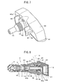
- FIG.11 is a vertical cross-sectional view of a third embodiment of a tyre valve unit according to the invention;
- FIG.12 is a vertical cross-sectional view of the tyre valve unit of FIG.11, before assembly of the resilient cylindrical member and the housing;
- FIG.13 is a transverse cross-sectional view of a part of the tyre valve unit of FIG.11;
- FIG.14 is a vertical cross-sectional view of a fourth embodiment of a tyre valve unit according to the invention;
- FIG.15 is a vertical cross-sectional view of the tyre valve unit of FIG.14, before assembly of the resilient cylindrical member and the housing;
- FIG.16 is a transverse cross-sectional view of a part of the tyre valve unit of FIG.14;
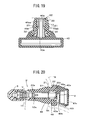
- FIG.17 is a vertical cross-sectional view of a fifth embodiment of a tyre valve unit according to the invention mounted on a wheel rim;
- FIG.18 is a vertical cross-sectional view of the tyre valve unit of FIG.17, before assembly of the resilient cylindrical member and the housing ;
- FIG.19 is a transverse cross-sectional view of a part of the tyre valve unit of FIG. 17;
- FIG.20 is a vertical cross-sectional view of an exemplary sixth embodiment of a tyre valve unit according to the invention;
- FIG.21 is a vertical cross-sectional view of the tyre valve unit of FIG.20, before assembly of the resilient cylindrical member and the housing;
- FIG.22 is a transverse cross-sectional view of a part of the tyre valve unit of FIG.20;
- FIG.23 is a front view of the housing of the tyre valve unit of FIG.20;
- FIG.24 is a side view of the housing of the tyre valve unit of FIG.20;
- FIG.25 is a perspective view of the housing of the tyre valve unit of FIG.20;
- FIG.26 is a vertical cross-sectional view of an exemplary seventh embodiment of a tyre valve unit according to the invention mounted on a wheel rim;
- FIG.27 is a vertical cross-sectional view of the tyre valve unit of FIG.26, before assembly of the resilient cylindrical member and the housing;
- FIG.28 is a transverse cross-sectional view of a part of the tyre valve unit of FIG.26;
- FIG.29 is a front view of the housing of the tyre valve unit of FIG.26;
- FIG.30 is a side view of the housing of the tyre valve unit of FIG.26; and
- FIG.31 is a perspective view of the housing of the tyre valve unit of FIG.26.
- Referring to FIGS.1-7, there is illustrated a tyre valve unit according to an exemplary embodiment, which is used for a tyre condition monitoring apparatus for monitoring tyre conditions such as pneumatic pressure, temperature, or the like, within a vehicle tyre. As shown in FIGS.1 and 2, a
tyre valve 1 is connected with atyre sensor 2 to provide a tyre valve unit U, which is mounted on a rim R for a vehicle wheel, with a resilientcylindrical member 20. As for components of thetyre sensor 2, various electronic parts, a battery, an antenna, and so on, may be included, and a transmitting function may be provided, so that the unit may be classified as a transmitting unit. In the present embodiment, however, thetyre sensor 2 is not limited to the transmitting unit, but corresponds to a sensor unit with at least a function for monitoring the tyre conditions. - As for the
tyre valve 1, a valve mechanism (V) is accommodated in ametallic valve body 10, and avalve stem 12 is formed integrally with thevalve body 10 to extend therefrom. The valve stem 12 is metallic, or may be made from synthetic resin to provide the rigid cylindrical member. Or, it may be made separately from thevalve body 10, and then connected together. The extending end portion of thevalve system 12 is enlarged in diameter to form anenlarged diameter portion 13, which is enclosed in the resilientcylindrical member 20 made of rubber, together with an expandedportion 11, which provides a boundary to thevalve body 10. - According to the exemplary embodiment as shown in FIGS.1-7, the resilient
cylindrical member 20 is a rubber member formed to enclose thevalve stem 12, as shown in FIGS.1 and 3, with its outer surface tapered. On the outer surface of the one end of the resilientcylindrical member 20, a first engagingportion 21 is integrally formed therewith to extend in a radial direction thereof, to be engaged with one side of the rim R. And, on the outer surface of the other one end of the resilientcylindrical member 20, a second engagingportion 22 is integrally formed therewith to extend in a radial direction thereof, to be engaged with the other one side of the rim R. The first engagingportion 21 and second engagingportion 22 may be each formed in the shape of an annular protrusion, respectively, or they may be formed, respectively, in such a configuration that a plurality of protrusions are formed in series along its outer circumference, with a plurality of clearances provided along the outer circumference. - Also, as a rigid annular member, a metallic
annular collar 30 made of brass, for example, having aflange portion 31, is fitted into one end of the other end portion of the resilientcylindrical member 20, i.e., on the same side thereof as ahousing 40. Practically, thecollar 30 and thevalve stem 12 may be integrally formed together by insert-forming, or vulcanized, to form the resilientcylindrical member 20 made of rubber, as shown in FIG.3. - On the other hand, the
housing 40 for thetyre sensor 2 is a case made from synthetic resin, and formed as shown in FIGS.3-7, such that an opening thereof facing the inner surface of the rim R is closed by alid member 41, after a sensor unit (not shown) is received in thehousing 40. Thehousing 40 is integrally formed with anextended portion 42 to be engaged with thecollar 30. And, theextended portion 42 is formed with a threadedportion 43 configured to be threaded with thecollar 30, and afree end portion 44, which is provided to extend from the threadedportion 43 into theenlarged diameter portion 13 of thevalve stem 12. In the threadedportion 43 and thefree end portion 44, apassage 40a is defined to open at the tip end of thefree end portion 44, and communicate with apassage 40b, which opens in a lateral direction of thehousing 40, at the side of the threadedportion 43. - Accordingly, when the tyre valve unit U is assembled as described later, and mounted on the rim R, it is held on the rim R between the first engaging
portion 21 and the second engagingportion 22, in such a state that the threadedportion 43 is threaded with thecollar 30 within the resilientcylindrical member 20, as shown in FIG.1. Then, as shown in FIG.1 and FIG.4, an annular space S1 is defined between the inner surface of the resilientcylindrical member 20 and theextended portion 42, at a position that corresponds to the position between the first engagingportion 21 and the second engagingportion 22 of the resilientcylindrical member 20. Also, as thefree end portion 44 is held in theenlarged diameter portion 13, a cylindrical space S2 is defined between the inner surface of theenlarged diameter portion 13 and the outer surface of thefree end portion 44. Therefore, the annular space S1 and the cylindrical space S2 are communicated with an inner space of the rim R (i.e., right space in FIG.1) through thepassages - According to the present embodiment, as apparent from the perspective view shown in FIG.7, a pair of lifted
wall potions portion 42, and integrally formed withribs lid member 41 has an outer lateral surface approximately in parallel with the inner surface of the rim R, such that a clearance between thelid member 41 and the rim R is set to be of a predetermined value. With thelid member 41 being formed as described above, in the case where centrifugal force is applied to the housing 40 (tyre sensor 2) when the vehicle is running, if deflection is caused in thehousing 40, the outer surface of thelid member 41 will be in contact with the inner surface of the rim R, so that the clearance between thelid member 41 and the rim R can be minimized. Therefore, even if thelid member 41 is forced to contact the rim R when the vehicle is running, a stably mounted state can be obtained. With respect to thetyre sensor 2, there are provided at least the function for monitoring the state of the tyre, as described above, and also the transmitting function, which functions are not directly related to the present invention, so that further explanation is omitted herein. - Next will be explained assembling the tyre valve unit U as constituted above and mounting it on the rim R for the vehicle wheel. The housing 40 (tyre sensor 2) as constituted in FIGS.5-7 is inserted into the
tyre valve 1 formed integrally with the resilientcylindrical member 20 and thecollar 30, as indicated by a blank arrow in FIG.3. Then, with thefree end portion 44 being accommodated in theenlarged diameter portion 13 of thevalve stem 12, the threadedportion 43 is threaded with thecollar 30. Consequently, thehousing 40 is held in such a state as being fixed to thecollar 30 securely. As a result, the annular space S1 is defined between the inner surface of the resilientcylindrical member 20 and theextended portion 42, and the cylindrical space S2 is defined between the inner surface of theenlarged diameter portion 13 and the outer surface of thefree end portion 44, as shown in FIG.4. Therefore, the annular space S1 is communicated with thepassages - With the
tyre valve 1 andtyre sensor 2 being assembled to be in the state as shown in FIG.1, the tyre valve unit U is formed. Then, one end of the tyre valve unit U at thecap 3's side thereof is passed through the hole Rh of the rim R, and the resilientcylindrical member 20 is pulled toward thecap 3. When the first engagingportion 21 of the resilientcylindrical member 20 gets over the hole Rh of the rim R, the resilientcylindrical member 20 is secured to the rim R, between the first engagingportion 21 and the second engagingportion 22. In this case, as the annular space S1 has been defined between the inner surface of the resilientcylindrical member 20 and theextended portion 42, a portion between the first engagingportion 21 and the second engagingportion 22 will be bent in the radial direction (toward the center of the axis), when the first engagingportion 21 of the resilientcylindrical member 20 gets over the hole Rh of the rim R, whereby the resilientcylindrical member 20 can be easily secured to the rim R. Then, if the resilientcylindrical member 20 is pulled further, the second engagingportion 22 is blocked by the rim R, so that it will not get over the rim R, and therefore the tyre valve unit U will be held in the state secured on the rim R. As a result, the tyre valve unit U is held in such a state that thelid member 41 of thehousing 40 is approximately in parallel with the inner surface of the rim R, with a small clearance being provided between them, as shown in FIG.2. In addition, as thecollar 30 serving as the rigid annular member has been secured to the open end portion of the housing in the resilientcylindrical member 20, the end portion of the resilientcylindrical member 20 can be prevented from being deformed, to maintain such a state that the tyre valve unit U is mounted on the rim R securely, and obtain a necessary sealing property against the rim R. - Next, with air being fed into the tyre, air pressure, i.e., so-called back pressure, is applied from the inner side of the rim R (right side in FIG.1) to the annular space S1 through the
passage 40b,passage 40a and cylindrical space S2, so that the portion between the first engagingportion 21 and the second engagingportion 22 in the resilientcylindrical member 20 is pressed to the open end surface of the rim R. Consequently, the necessary sealing property can be maintained between the resilientcylindrical member 20 and the rim R, and even if the thickness of the rim R is thin, the air-tight relationship between them can be maintained. In addition, as the rim R is rotating, the centrifugal force will be applied to the tyre valve unit U in the radial direction. According to the present embodiment, however, thevalve stem 12 serving as the rigid cylindrical member is separated from thehousing 40, and these are connected by the resilientcylindrical member 20 to form a flexible structure, so that the centrifugal force can be compensated appropriately. Accordingly, without considering any possibility of the problem raised in the prior unit of the rigid structure, the tyre valve unit U can be secured to the rim R in a stable state. And, as the threadedportion 43 is threaded with thecollar 30, thetyre valve 1 and the housing 40 (tyre sensor 2) are held to be in such a state that they are mounted on the rim R securely, and function as the tyre valve unit U in the stable state. - Furthermore, as the rim R rotates at higher speed, larger centrifugal force will be applied to the tyre valve unit U, such that a relative displacement may be created between the
enlarged diameter portion 13 of thevalve stem 12 and thefree end portion 44 of the extendedportion 42. With the cylindrical space S2 being formed between those portions, however, the relative displacement between theenlarged diameter portion 13 and thefree end portion 44 against the resilient force of the resilientcylindrical member 20 may be allowed. Thus, with the relative displacement created between theenlarged diameter portion 13 and thefree end portion 44, the centrifugal force can be compensated appropriately. If a load of more than the force for creating the relative displacement is applied to the tyre valve unit U, thefree end portion 44 comes into contact with the inner surface of theenlarged diameter portion 13, to restrict a further relative displacement, so that the function of the tyre valve unit U will not be deteriorated. - FIGS.8-10 show another embodiment of the present invention. In contrast to the aforementioned embodiment, wherein the threaded
portion 43 and thefree end portion 44 are formed integrally with thehousing 40, according to the present embodiment, ametallic tube 45 serving as the rigid support member is held at its one end portion in the threadedportion 43, for supporting a free end portion of themetallic tube 45 to extend into the resilientcylindrical member 20, and into theenlarged diameter portion 13. Instead of thefree end portion 44 being made from synthetic resin integrally with thehousing 40, themetallic tube 45 is employed to raise its strength. As shown in FIG.8, anannular groove 45s is formed on one end of themetallic tube 45, and the threadedportion 43 is formed to enclose therein a portion of themetallic tube 45 formed with theannular groove 45s (then, theextended portion 42 and the main body of thehousing 40 are formed), according to an integrally forming process with resin, so that themetallic tube 45 is secured to the threadedportion 43 firmly. As other elements as shown in FIGS.8-10 are substantially the same as those shown in FIGS.1-7, assembling manners and functions are approximately equal, and like effect can be obtained, explanation of those elements is omitted herein, with the same reference numerals being applied to elements which are substantially the same as those shown in FIGS.1-7. - FIGS.11-19 show three exemplary embodiments, which are integrally provided with a metallic tube serving as the rigid support member, respectively, like the embodiment as shown in FIGS.8-10, and which will be explained in sequence hereinafter. As other elements as shown in FIGS.11-19 are substantially the same as those shown in FIGS.1-7, assembling manners and functions are approximately equal, and like effect can be obtained, explanation of those elements is omitted herein, with the same reference numerals being applied to those substantially the same as the elements as shown in FIGS.1-7.
- At the outset, according to the embodiment as shown in FIGS.11-13, a
metallic tube 45x serving as the rigid support member extends from the threadedportion 43 to thefree end portion 44, and enclosed with synthetic resin along the whole longitudinal length of themetallic tube 45x, to be formed integrally with thehousing 40. According to the present embodiment, themetallic tube 45x is employed to raise its strength, like the embodiment as shown in FIGS.8-10. In addition, themetallic tube 45x is integrally provided with a flange portion 45xf at its rear end. Theextended portion 42 including the threadedportion 43 andfree end portion 44, and the main body of thehousing 40 are formed by the integrally forming process with synthetic resin, to enclose themetallic tube 45x and flange portion 45xf. Therefore, themetallic tube 45x is securely held in thehousing 40, with thepassage 40a being formed in themetallic tube 45x. According to the embodiments as shown in FIGS.11-13, apassage 40c opens upward in FIG.11, i.e., in a different direction from thepassage 40b as shown in FIGS.8-10, which opens downward. Thus, as thepassage 40c and thepassage 40b open at different positions, they are indicated by different reference numerals, but they have substantially the same function, in other embodiments described hereinafter with reference to FIGS.14-19, as well. - Then, FIGS.14-16 show the embodiment wherein a
metallic tube 45y serving as the rigid support member is held at its front end by the threadedportion 43, and formed at its rear end integrally with a flange portion 45yf. Theextended portion 42 including the threadedportion 43 andfree end portion 44, and the main body of thehousing 40 are formed by the integrally forming process with synthetic resin, to enclose themetallic tube 45y and flange portion 45yf. Therefore, themetallic tube 45y is securely held in the vicinity of the threadedportion 43 in thehousing 40. According to the present embodiment, a part of thepassage 40a is constituted by themetallic tube 45y, and communicated with thepassage 40c through themetallic tube 45y. - According to the embodiment as shown in FIGS.17-19, a
metallic tube 45z serving as the rigid support member is formed at its rear end with a threaded portion 45zb, which is configured to be equal to the threadedportion 43, and formed at its front end with a free end portion 45za, which is configured to be equal to thefree end portion 44. Themetallic tube 45z is supported by thehousing 40, with the free end portion 45za being extended into the resilientcylindrical member 20, and further into theenlarged diameter portion 13. That is, themetallic tube 45z is used to raise its strength furthermore, and thehousing 40 is formed by the integrally forming process with synthetic resin, to enclose the rear end portion of the threaded portion 45zb. Therefore, themetallic tube 45z is securely held in thehousing 40. Also, with the threaded portion 45zb being engaged with thecollar 30, a securely engaged state can be made according to the metallic threaded connection between them. - Next, FIGS.20-25 and FIGS.26-31 illustrate other exemplary embodiments, which are different in structure, with respect to the extended portion and the valve stem, and slightly different in connecting structure of the
tyre valve 1 and the housing 40 (tyre sensor 2), comparing with the aforementioned embodiments. However, the function of the annular space S1 as defined with other elements assembled to form the tyre valve unit U, is substantially the same as that in the aforementioned embodiments. Therefore, although thevalve stem 12, resilientcylindrical member 20,collar 30 andhousing 40 are indicated by the reference numerals with "x" added to those as shown in FIGS.1-7, explanation of other elements is omitted herein, with the same reference numerals being applied to those substantially the same as the elements as shown in FIGS.1-7. - According to the exemplary embodiment as shown in FIGS.20-25, a
housing 40x is a case made from synthetic resin, such that its opening end formed in the same direction as the longitudinal axis of thetyre valve 1 is closed by alid member 41x, after the sensor unit (not shown) of thetyre sensor 2 is received in the hosing 40x. Thehousing 40x has an extendedportion 48 to be engaged with acollar 30x, at its opposite side to thelid member 41x. Theextended portion 48 of the present embodiment is integrally formed with thehousing 40x, and formed at its tip end with afork portion 49 to be engaged with thecollar 30x. Along the longitudinal axis of the extendedportion 48, thefork portion 49 is formed with a plurality ofslits 48s (as indicated in FIG.23), to provide a plurality of divided parts. With the elements being assembled to be mounted on the rim R, as described later, the tyre valve unit U is held by the rim R between the first engagingportion 21 and the second engagingportion 22 in the resilientcylindrical member 20, as shown in FIG.20, in such a state that thefork portion 49 is engaged with thecollar 30x in the resilientcylindrical member 20x. - As shown in FIG.22, on the
housing 40x, there is formed aprotrusion 40p, which is adapted to come into contact with the open end surface of the resilientcylindrical member 20x, when thefork portion 49 is engaged with thecollar 30x in the resilientcylindrical member 20x. That is, when thefork portion 49 is engaged with thecollar 30x as shown in FIG.20 and FIG.22, the engaged state between thefork portion 49 and thecollar 30x is maintained with resilient force created on a contacting portion of the resilientcylindrical member 20x, which is compressed by theprotrusion 40p. According to the present embodiment, the annular space S1 is defined between the inner surface of the resilientcylindrical member 20x and the fork portion 49 (extended portion 48) of thehousing 40x, at such a position that approximately corresponds to the position between the first engagingportion 21 and the second engagingportion 22 of the resilientcylindrical member 20x, as shown in FIG.20 and FIG.22. This annular space S1 is communicated with outside of thehousing 40x through thepassages - According to the present embodiment, a
guide portion 40t is formed on the outer surface ofhousing 40x, which faces the inner surface of the rim R. Theguide portion 40t is formed with the outer surface approximately in parallel with the inner surface of the rim R, to set the clearance between thehousing 40x and the rim R to be of a predetermined value. With theguide portion 40t being formed as described above, in the case where the centrifugal force is applied to thehousing 40x (tyre sensor 2) when the vehicle is running, if deflection is caused in thehousing 40x, the outer surface of theguide portion 40t will be in contact with the inner surface of the rim R, so that the clearance between theguide portion 40t and the rim R can be minimized. Therefore, even if thehousing 40x is forced to contact the rim R when the vehicle is running, a stably mounted state can be obtained. - Next will be explained assembling the tyre valve unit U as constituted above and mounting it on the rim R for the vehicle wheel. The
housing 40x (tyre sensor 2) as constituted in FIGS.23-25 is inserted into thetyre valve 1 formed integrally with the resilientcylindrical member 20x and thecollar 30x, as indicated by a blank arrow in FIG.21, so that thefork portion 49 is engaged with thecollar 30x in the resilientcylindrical member 20x. As the extended portion 48 (fork portion 49) is formed with theslits 48s, thefork portion 49 is bent in the radial direction when thefork portion 49 passes through the opening of thecollar 30x, so that thefork portion 49 easily gets over thecollar 30x, to be engaged with the open end portion thereof, and held in the state as shown in FIG.20 and FIG.22. In this case, theprotrusion 40p presses the end surface of the resilientcylindrical member 20x, so that thefork portion 49 is engaged with thecollar 30x, with the resilientcylindrical member 20x being compressed. Therefore, thefork portion 49 is held to be securely engaged with the open end of thecollar 30x, by the resilient force of the resilientcylindrical member 20x after the former was engaged with the latter. - With the
tyre valve 1 andtyre sensor 2 being assembled to be in the state as shown in FIG.20, the tyre valve unit U is formed. Then, one end of the tyre valve unit U at thecap 3's side thereof is passed through the hole Rh of the rim R, and the resilientcylindrical member 20x is pulled toward thecap 3. When the first engagingportion 21 of the resilientcylindrical member 20x gets over the hole Rh of the rim R, the resilientcylindrical member 20x is secured to the rim R, between the first engagingportion 21 and the second engagingportion 22. In this case, as the annular space S1 has been defined between the inner surface of the resilientcylindrical member 20x and theextended portion 48, a portion between the first engagingportion 21 and the second engagingportion 22 will be bent in the radial direction (toward the center of the axis), when the first engagingportion 21 of the resilientcylindrical member 20x gets over the hole Rh of the rim R, whereby the resilientcylindrical member 20x can be easily secured to the rim R. Then, if the resilientcylindrical member 20x is pulled further, the second engagingportion 22 is blocked by the rim R, so that it will not get over the rim R, and therefore the tyre valve unit U will be held in the state secured on the rim R. As a result, the tyre valve unit U is held in such a state that thehousing 40x is approximately in parallel with the inner surface of the rim R, with a small clearance being provided between them. With respect to the function and effect achieved after it was installed, such as the manner for obtaining the sealing property with the annular space S1, the explanation is omitted herein, because they are the same as those as described with reference to FIGS.1-7. - FIGS.26-31 show a further embodiment of the present invention, wherein a
collar 50 serving as the rigid annular member corresponds to thecollar 30x as described before, and wherein anannular groove 51 is formed on the inner surface of thecollar 50, so that anextended portion 62 of ahousing 60 is engaged with theannular groove 51. In other words, according to the present embodiment, thecollar 50 is different in shape from thecollar 30x as shown in FIGS.20-22, theextended portion 62 is different in shape from the extendedportion 48 as shown in FIGS.20-22, and its height (longitudinal length) is approximately equal to the height (longitudinal length) of thecollar 50. Therefore, the housing 60 (tyre sensor 2) is assembled with thetyre valve 1 in such a state as shown in FIG.26, whereby the total longitudinal length can be reduced. - Also, according to the present embodiment, an annular space S3 is defined between the inner surface of a resilient
cylindrical member 20y and the outer surface of thevalve stem 12x at such a position that corresponds to the position between the first engagingportion 21 and the second engagingportion 22 of the resilientcylindrical member 20y. As shown in FIG.27, thecollar 50 and thevalve stem 12x are integrally formed together by insert-forming, or vulcanized, to form the resilientcylindrical member 20y made of rubber. According to the present embodiment, however, thecollar 50 is made larger in its inner diameter than that disclosed in FIG.20 and FIG.21, and the annular space S3 opens to the outside space without being blocked by thecollar 50. Therefore, a forming die used for the insert-forming can be made easily, so that a relatively inexpensive product can be produced. As other elements are substantially the same as those shown in the embodiment as illustrated in FIGS.20-25, explanation of those elements is omitted herein. - Next will be explained assembling the tyre valve unit U as shown in FIG.26. The housing 60 (tyre sensor 2) as constituted in FIGS.28-31 is inserted into the
tyre valve 1 formed integrally with the resilientcylindrical member 20y and thecollar 50, as indicated by a blank arrow in FIG.27. As a result, afork portion 63 of the extendedportion 62 is engaged with theannular groove 51. In this case, theextended portion 62 is formed with a plurality ofslits 64. When thefork portion 63 is engaged with theannular groove 51 of thecollar 50, it is bent in the radial direction (toward the center of the axis), to be easily engaged with theannular groove 51, and held in the state as shown in FIGS.26 and 28. In addition, theprotrusion 65 presses the end surface of the resilientcylindrical member 20y, so that theextended portion 62 is engaged with thecollar 50, with the resilientcylindrical member 20y being compressed. Therefore, thefork portion 63 is held to be securely engaged with theannular groove 51 of thecollar 50, by the resilient force of the resilientcylindrical member 20y after the former was engaged with the latter. - According to the present embodiment, therefore, when the
tyre valve 1 is assembled with thetyre sensor 2, the tyre valve unit U as shown in FIG.26 is constituted. Then, one end of the tyre valve unit U at thecap 3's side thereof is passed through the hole Rh of the rim R, and the resilientcylindrical member 20y is pulled toward thecap 3, whereby the tyre valve unit U is secured to the rim R. In this case, as the annular space S3 has been defined between the inner surface of the resilientcylindrical member 20y and the outer surface of thevalve stem 12x, a portion between the first engagingportion 21 and the second engagingportion 22 will be bent in the radial direction (toward the center of the axis), when the first engagingportion 21 of the resilientcylindrical member 20y gets over the hole Rh of the rim R, whereby the resilientcylindrical member 20y can be easily secured to the rim R. As a result, the tyre valve unit U is held in such a state that thehousing 60 is approximately in parallel with the inner surface of the rim R, with a small clearance being provided between them, as shown in FIG.26. - According to the present embodiment, a pair of lifted
wall potions portion 62, withribs guide portion 68 is formed on the outer surface ofhousing 60, which faces the inner surface of the rim R, so that the clearance between theguide portion 68 and the rim R can be minimized. Therefore, even if thehousing 60 is forced to contact the rim R when the vehicle is running, a stably mounted state can be obtained. With respect to the function and effect achieved after it was installed, such as the manner for obtaining the sealing property with the annular space S3, the explanation is omitted herein, because they are the same as those as described with reference to FIGS.1-7.
Claims (20)
- A tyre valve unit for mounting on a wheel rim (R) for a vehicle, comprising:a tyre valve (1) having a valve body (10) and a rigid cylindrical member (12, 12x) extended from the valve body(10);a tyre sensor (2) accommodated in a housing (40, 40x, 60) having an extended portion (42, 48, 62) with a passage (40a) defined therein, the extended portion (42, 48, 62) positioned in series with the rigid cylindrical member (12, 12x);a resilient cylindrical member (20, 20x, 20y) configured to accommodate the rigid cylindrical member (12, 12x), and formed with a first engaging portion (21) and a second engaging portion (22) on an outer surface of the resilient cylindrical member (20, 20x, 20y), the first engaging portion (21) and the second engaging portion (22) provided to extend in a radial direction of the resilient cylindrical member (20, 20x, 20y), respectively, such that when the tyre valve unbit is mounted on a wheel rim (R) the rim (R) is held between the first engaging portion (21) and the second engaging portion (22); anda rigid annular member (30, 30x, 50) secured to an open end of the resilient cylindrical member (20, 20x, 20y), the extended portion (42, 48, 62) of the housing (40, 40x, 60) being engaged with the rigid annular member (30, 30x, 50) in the resilient cylindrical member (20, 20x, 20y), such that an annular space (S1, S3) is defined between the extended portion (42, 48, 62) of the housing (40, 40x, 60) and an inner surface of the resilient cylindrical member (20, 20x, 20y) approximately corresponding to the outer surface of the resilient cylindrical member (20, 20x, 20y) between the first engaging portion (21) and the second engaging portion (22), and that the annular space (S1, S3) communicates with outside of the housing (40, 40x, 60) through the passage (40a) of the extended portion (42, 48, 62).
- A tyre valve unit as set forth in claim 1, wherein the extended portion (42) of the housing (40) comprises a threaded portion (43) configured to be threaded with the rigid annular member (30) in the resilient cylindrical member (20), and a free end portion (44) provided to extend from the threaded portion (43) into the resilient cylindrical member (20), the passage (40a) being defined in the threaded portion (43) and the free end portion (44) to communicate the annular space (S1) with outside of the housing (40).
- A tyre valve unit as set forth in claim 2, wherein the rigid cylindrical member (12) is configured to form an enlarged diameter portion (13) enlarged in a radial direction thereof, such that the free end portion (44) of the housing (40) is accommodated in the enlarged diameter portion (13) of the rigid cylindrical member (12), and that a cylindrical space (S2) is defined between the outer surface of the free end portion (44) of the housing (40) and an inner surface of the enlarged diameter portion (13) of the rigid cylindrical member (12), the passage (40a) being defined in the threaded portion (43) and the free end portion (44) to communicate the annular space (S1) and the cylindrical space (S2) with outside of the housing (40).
- A tyre valve unit as set forth in claim 1, wherein the extended portion (42) of the housing (40) comprises a threaded portion (43) configured to be threaded with the rigid annular member (30) in the resilient cylindrical member (20), and wherein a rigid support member (45) is held at one end thereof by the threaded portion (43), such that a free end portion of the rigid support member (45) extends from the threaded portion (43) into the resilient cylindrical member (20), the passage (40a) being defined in the threaded portion (43) and the rigid support member (45) to communicate the annular space (S1) with outside of the housing (40).
- A tyre valve unit as set forth in claim 4, wherein the rigid cylindrical member (12) is configured to form an end portion enlarged in a radial direction thereof, such that the free end portion of the rigid support member (45) is accommodated in the enlarged diameter portion (13) of the rigid cylindrical member (12), and that a cylindrical space (S2) is defined between the outer surface of the free end portion of the rigid support member (45) and an inner surface of the enlarged diameter portion (13) of the rigid cylindrical member (12), the passage (40a) being defined in the threaded portion (43) and the rigid support member (45) to communicate the annular space (S1) and the cylindrical space (S2) with outside of the housing (40).
- A tyre valve unit as set forth in claim 4, wherein the rigid support member comprises a metallic tube (45) secured at one end thereof to the threaded portion (43) of the housing (40).
- A tyre valve unit as set forth in claim 4, wherein the rigid cylindrical member (12) comprises a metallic tube (45x) integrally accommodated in the housing (40), the metallic tube (45x) provided to extend from the threaded portion (43) to the free end portion (44), the passage (40a) being defined in the metallic tube(45x).
- A tyre valve unit as set forth in claim 1, wherein the extended portion (42) of the housing (40) comprises a threaded portion (43) configured to be threaded with the rigid annular member (30) in the resilient cylindrical member (20), and wherein a rigid support member (45y) is held at one end thereof in the threaded portion (43), and formed at the other one end of the rigid support member (45y) with a flange portion (45yf) held in the housing (40), the passage being defined in the threaded portion (43) and the rigid support member (45y).
- A tyre valve unit as set forth in claim 1, wherein the extended portion of the housing (40) comprises a rigid support member (45z) having a threaded portion (45zb) configured to be threaded with the rigid annular member (30) in the resilient cylindrical member (20), and having a free end portion (45za) configured to extend from the threaded portion (45zb) into the resilient cylindrical member (20), the passage (40a) being defined in the rigid support member (45z).
- A tyre valve unit as set forth in claim 9, wherein the rigid support member is a metallic tube (45z) having the threaded portion (45zb) and the free end portion (45za), and wherein the metallic tube (45z) is integrally connected to the housing (40) at the end of the threaded portion (45zb).
- A tyre valve unit as set forth in claim 1, wherein the resilient cylindrical member (20, 20x, 20y) is made of rubber, and wherein the rigid annular member (30, 30x, 50) is fitted into the open end of the resilient cylindrical member (20, 20x, 20y).
- A tyre valve unit as set forth in claim 11, wherein the rigid annular member (30) comprises a metallic collar (30) formed therein with threads, and formed at an end thereof with a flange (31) to be in contact with the housing (40).
- A tyre valve unit as set forth in claim 1, wherein the extended portion (48, 62) of the housing (40x, 60) comprises a fork portion (49, 63) configured to be engaged with the rigid annular member (30x, 50) in the resilient cylindrical member (20x, 20y), and wherein the rim (R) is held between the first engaging portion (21) and the second engaging portion (22) of the resilient cylindrical member (20x, 20y), with the fork portion (49, 63) being engaged with the rigid annular member (30x, 50) in the resilient cylindrical member (20x, 20y).
- A tyre valve unit as set forth in claim 13, wherein the resilient cylindrical member (20x, 20y) is made of rubber, and wherein the rigid annular member (30x, 50) is integrally secured to the open end of the resilient cylindrical member (20x, 20y).
- A tyre valve unit as set forth in claim 14, wherein the housing (40x, 60) comprises a protrusion (40p, 65) placed to be in contact with the open end of the resilient cylindrical member (20x, 20y), with the fork portion (49, 63) being engaged with the rigid annular member (30x, 50) in the resilient cylindrical member (20x, 20y), and wherein the engaging state of the fork portion (49, 63) with the rigid annular member (30x, 50) is held by resilient force of the resilient cylindrical member (20x, 20y), which is produced in response to pressing force of the protrusion (40p, 65) against the resilient cylindrical member (20x, 20y), the pressing force being produced when the fork portion (49, 63) is engaged with the rigid annular member (30x, 50).
- A tyre valve unit as set forth in claim 13, wherein the annular space (S1) is defined between the fork portion (49) and the inner surface of the resilient cylindrical member (20x) approximately corresponding to the outer surface of the resilient cylindrical member (20x) between the first engaging portion (21) and the second engaging portion (22) of the resilient cylindrical member (20x).
- A tyre valve unit as set forth in claim 13, wherein the rigid annular member (50) is formed on the inner surface thereof with an annular groove (51), with which the fork portion (63) is engaged.
- A tyre valve unit as set forth in claim 17, wherein the annular space (S3) is defined between the inner surface of the resilient cylindrical member (20y) and the outer surface of the end portion of the rigid cylindrical member (12x) approximately corresponding to the outer surface of the resilient cylindrical member (20y) between the first engaging portion (21) and the second engaging portion (22) of the resilient cylindrical member (20y).
- A tyre valve unit as set forth in claim 18, wherein the fork portion (63) is formed along a longitudinal axis thereof with a plurality of slits, to provide a plurality of divided parts.
- A tyre valve unit as set forth in claim 13, wherein the housing (40x, 60) has an outer side surface placed in parallel with an inner side surface of the rim (R), and wherein the housing (40x, 60) comprises a guide portion (40t, 68) for providing a clearance between the rim (R) and the housing (40x, 60) to be of a constant value.
Applications Claiming Priority (3)
| Application Number | Priority Date | Filing Date | Title |
|---|---|---|---|
| JP2005181521 | 2005-06-22 | ||
| JP2005324637 | 2005-11-09 | ||
| JP2006019054A JP4522953B2 (en) | 2005-06-22 | 2006-01-27 | Tire valve unit |
Publications (1)
| Publication Number | Publication Date |
|---|---|
| EP1736328A1 true EP1736328A1 (en) | 2006-12-27 |
Family
ID=36954964
Family Applications (1)
| Application Number | Title | Priority Date | Filing Date |
|---|---|---|---|
| EP06075538A Withdrawn EP1736328A1 (en) | 2005-06-22 | 2006-03-07 | Tyre valve unit for a vehicle |
Country Status (3)
| Country | Link |
|---|---|
| US (1) | US20060288924A1 (en) |
| EP (1) | EP1736328A1 (en) |
| JP (1) | JP4522953B2 (en) |
Cited By (7)
| Publication number | Priority date | Publication date | Assignee | Title |
|---|---|---|---|---|
| FR2899152A1 (en) * | 2006-09-27 | 2007-10-05 | Siemens Vdo Automotive Sas | "METHOD OF FIXING A PRESSURE SENSOR ON A MOTOR VEHICLE RIM, AND CORRESPONDING FASTENING DEVICE" |
| DE102006042565A1 (en) * | 2006-09-11 | 2008-03-27 | Global Dynamix Ag | Vehicle tire pressure measurement unit |
| EP1911610A1 (en) * | 2006-10-10 | 2008-04-16 | Pacific Industrial Co., Ltd. | Tire valve unit |
| DE102006056470A1 (en) * | 2006-11-28 | 2008-05-29 | Alligator Ventilfabrik Gmbh | Valve assembly and kit for a valve assembly |
| FR2918315A1 (en) * | 2007-07-06 | 2009-01-09 | Siemens Vdo Automotive Sas | ELECTRONIC MEASURING UNIT FOR THE PARAMETERS OF OPERATION OF A VEHICLE WHEEL, COMPRISING AN ELECTRONIC HOUSING AND A "SNAP IN" INFLATION VALVE |
| WO2010054548A1 (en) * | 2008-11-17 | 2010-05-20 | 杭州万通气门嘴有限公司 | Tire valve for vehicle |
| GB2526893A (en) * | 2014-06-06 | 2015-12-09 | E Lead Electronic Co Ltd | Reinforced tire valve of tire pressure detecting device |
Families Citing this family (16)
| Publication number | Priority date | Publication date | Assignee | Title |
|---|---|---|---|---|
| JP4460593B2 (en) * | 2007-09-19 | 2010-05-12 | 本田技研工業株式会社 | Vehicle wheel |
| JP5437916B2 (en) * | 2010-06-02 | 2014-03-12 | 太平洋工業株式会社 | Tire valve unit |
| JP5504132B2 (en) * | 2010-10-25 | 2014-05-28 | 太平洋工業株式会社 | Snap-in valve and tire valve unit |
| FR2978378B1 (en) * | 2011-07-28 | 2013-09-06 | Continental Automotive France | ELECTRONIC MEASURING UNIT FOR PARAMETERS FOR OPERATING A VEHICLE WHEEL, COMPRISING AN ELECTRONIC HOUSING AND AN INFLATION VALVE |
| CN103538432A (en) * | 2012-07-17 | 2014-01-29 | 联创汽车电子有限公司 | Monitoring sensor for pressure of tire |
| JP2014073843A (en) * | 2014-01-27 | 2014-04-24 | Pacific Ind Co Ltd | Snap-in valve and tire valve unit |
| JP6215160B2 (en) * | 2014-09-08 | 2017-10-18 | 太平洋工業株式会社 | Tire valve |
| JP6333205B2 (en) * | 2015-03-23 | 2018-05-30 | 太平洋工業株式会社 | Tire valve |
| JP6377583B2 (en) * | 2015-08-20 | 2018-08-22 | 太平洋工業株式会社 | Air pressure detection device |
| KR101897889B1 (en) | 2016-02-03 | 2018-09-12 | 다이헤요 고교 가부시키가이샤 | Tire valve unit |
| US10787048B2 (en) | 2016-06-28 | 2020-09-29 | Honda Motor Co., Ltd. | Holding structure for tire air pressure detecting device |
| FR3072328B1 (en) * | 2017-10-16 | 2020-03-27 | Continental Automotive France | INFLATION VALVE FOR TIRE RIM WITH ELASTIC DEFORMATION LIMITATION |
| FR3077768B1 (en) * | 2018-02-09 | 2020-01-17 | Continental Automotive France | ELECTRONIC UNIT FOR MEASURING OPERATING PARAMETERS OF A VEHICLE WHEEL, INCLUDING AN ELECTRONIC UNIT AND AN ELASTIC DEFORMATION TYPE INFLATION VALVE |
| US11007827B2 (en) * | 2018-06-27 | 2021-05-18 | Ford Global Technologies, Llc | Tire-pressure-monitoring system |
| EP4725719A1 (en) | 2024-01-31 | 2026-04-15 | Pacific Industrial Co., Ltd. | Tire valve and cover sleeve |
| WO2025163778A1 (en) | 2024-01-31 | 2025-08-07 | 太平洋工業株式会社 | Tire valve and tilt restriction member |
Citations (5)
| Publication number | Priority date | Publication date | Assignee | Title |
|---|---|---|---|---|
| US6005480A (en) | 1998-05-20 | 1999-12-21 | Schrader-Bridgeport International, Inc. | Tire valve and associated tire pressure sending unit |
| JP2001174356A (en) | 1999-12-20 | 2001-06-29 | Pacific Ind Co Ltd | Tire air pressure sensor |
| US20040084124A1 (en) * | 2002-11-04 | 2004-05-06 | Eaton Corporation | Snap in valve stem |
| US6851308B2 (en) | 2002-05-07 | 2005-02-08 | Siemens Vdo Automotive | Device for fixing a pressure sensor intended to be mounted in a tire |
| US20050087007A1 (en) * | 2003-10-24 | 2005-04-28 | Lear Corporation | Tire monitor system with spring retention clip |
Family Cites Families (8)
| Publication number | Priority date | Publication date | Assignee | Title |
|---|---|---|---|---|
| JPS60161603U (en) * | 1984-04-05 | 1985-10-26 | 太平洋工業株式会社 | Valve with tire pressure display device |
| IT209132Z2 (en) * | 1986-03-04 | 1988-09-12 | Bridgeport Brass Spa | VALVE IMPROVEMENTS FOR TUBELESS TIRES. |
| ATE91254T1 (en) * | 1986-10-20 | 1993-07-15 | Leeuwen Nelda Faith Van | PRESSURE GAUGE VALVE STEM. |
| US5094263A (en) * | 1991-08-02 | 1992-03-10 | General Motors Corporation | Tire pressure management actuator with bypass leakage prevention |
| JP2006151295A (en) * | 2004-11-30 | 2006-06-15 | Pacific Ind Co Ltd | Snap-in valve device |
| JP4633642B2 (en) * | 2006-02-06 | 2011-02-16 | 太平洋工業株式会社 | Tire pressure detecting device and tire monitoring system |
| JP2007287019A (en) * | 2006-04-19 | 2007-11-01 | Pacific Ind Co Ltd | Tire monitoring wireless circuit and tire monitoring system |
| JP2007290664A (en) * | 2006-04-27 | 2007-11-08 | Pacific Ind Co Ltd | Tire pressure detection side receiving circuit and tire monitoring system |
-
2006
- 2006-01-27 JP JP2006019054A patent/JP4522953B2/en not_active Expired - Fee Related
- 2006-02-22 US US11/358,068 patent/US20060288924A1/en not_active Abandoned
- 2006-03-07 EP EP06075538A patent/EP1736328A1/en not_active Withdrawn
Patent Citations (5)
| Publication number | Priority date | Publication date | Assignee | Title |
|---|---|---|---|---|
| US6005480A (en) | 1998-05-20 | 1999-12-21 | Schrader-Bridgeport International, Inc. | Tire valve and associated tire pressure sending unit |
| JP2001174356A (en) | 1999-12-20 | 2001-06-29 | Pacific Ind Co Ltd | Tire air pressure sensor |
| US6851308B2 (en) | 2002-05-07 | 2005-02-08 | Siemens Vdo Automotive | Device for fixing a pressure sensor intended to be mounted in a tire |
| US20040084124A1 (en) * | 2002-11-04 | 2004-05-06 | Eaton Corporation | Snap in valve stem |
| US20050087007A1 (en) * | 2003-10-24 | 2005-04-28 | Lear Corporation | Tire monitor system with spring retention clip |
Cited By (13)
| Publication number | Priority date | Publication date | Assignee | Title |
|---|---|---|---|---|
| DE102006042565A1 (en) * | 2006-09-11 | 2008-03-27 | Global Dynamix Ag | Vehicle tire pressure measurement unit |
| FR2899152A1 (en) * | 2006-09-27 | 2007-10-05 | Siemens Vdo Automotive Sas | "METHOD OF FIXING A PRESSURE SENSOR ON A MOTOR VEHICLE RIM, AND CORRESPONDING FASTENING DEVICE" |
| EP1911610A1 (en) * | 2006-10-10 | 2008-04-16 | Pacific Industrial Co., Ltd. | Tire valve unit |
| US7469581B2 (en) | 2006-10-10 | 2008-12-30 | Pacific Industrial Co., Ltd. | Tire valve unit |
| DE102006056470A1 (en) * | 2006-11-28 | 2008-05-29 | Alligator Ventilfabrik Gmbh | Valve assembly and kit for a valve assembly |
| WO2009007035A1 (en) * | 2007-07-06 | 2009-01-15 | Continental Automotive France | Electronic unit for measuring the operating parameters of a vehicle wheel, comprising an electronic module and a snap-in type inflation valve |
| FR2918315A1 (en) * | 2007-07-06 | 2009-01-09 | Siemens Vdo Automotive Sas | ELECTRONIC MEASURING UNIT FOR THE PARAMETERS OF OPERATION OF A VEHICLE WHEEL, COMPRISING AN ELECTRONIC HOUSING AND A "SNAP IN" INFLATION VALVE |
| US7587935B2 (en) | 2007-07-06 | 2009-09-15 | Continental Automotive France | Electronic unit for measuring operating parameters of a vehicle wheel, comprising an electronic box and an inflation valve of the snap-in type |
| US8286474B2 (en) | 2007-07-06 | 2012-10-16 | Continental Automotive France | Electronic module for measuring operating parameters of a vehicle wheel, comprising an electronic unit and an inflation valve of the “snap-in” type |
| WO2010054548A1 (en) * | 2008-11-17 | 2010-05-20 | 杭州万通气门嘴有限公司 | Tire valve for vehicle |
| JP2012506814A (en) * | 2008-11-17 | 2012-03-22 | 杭州万通气▲門▼嘴有限公司 | Air valve for automobile tire |
| KR101279194B1 (en) | 2008-11-17 | 2013-06-26 | 지에너 장 | Tire valve for vehicle |
| GB2526893A (en) * | 2014-06-06 | 2015-12-09 | E Lead Electronic Co Ltd | Reinforced tire valve of tire pressure detecting device |
Also Published As
| Publication number | Publication date |
|---|---|
| JP4522953B2 (en) | 2010-08-11 |
| JP2007153298A (en) | 2007-06-21 |
| US20060288924A1 (en) | 2006-12-28 |
Similar Documents
| Publication | Publication Date | Title |
|---|---|---|
| EP1736328A1 (en) | Tyre valve unit for a vehicle | |
| US20060125612A1 (en) | Valve device | |
| EP1911610B1 (en) | Tire valve unit | |
| US20080250852A1 (en) | Electronic unit for measuring operating parameters of a vehicle wheel | |
| KR20040012927A (en) | Wheel for a motor with pneumatic tyres, and arrangement comprising a valve, a tyre pressure measuring device and a spring holding the latter in the pneumatic tyre | |
| EP1241028B1 (en) | Mounting of transmitter casing on valve stem | |
| EP1452347B1 (en) | Casing structure of transmitter for use in tire condition monitoring apparatus | |
| US6694807B2 (en) | Wheel rim having a tire sensor for a pneumatic tire | |
| US5956820A (en) | Fastening device for an electronic module | |
| US9878604B2 (en) | Liquid-sealed antivibration device | |
| US8690208B2 (en) | Pressure-based crash detection system incorporated in side rail | |
| US7937998B2 (en) | Sensor mount with self-tightening device | |
| KR102063682B1 (en) | Top mount assembly and method of manufacturing same | |
| JP4914741B2 (en) | Bound stopper, bound stopper assembly, and bound stopper mounting structure for vehicle body | |
| US6619129B2 (en) | Three-piece pressure sensor with high pressure stainless steel sensing element | |
| US20050087007A1 (en) | Tire monitor system with spring retention clip | |
| EP1683657A1 (en) | Tyre monitoring unit for a vehicle | |
| KR100648155B1 (en) | Bearing device | |
| US5992816A (en) | Engine mount having a reference position indicating unit | |
| US20200207165A1 (en) | Tire condition detecting device, clamp-in valve, and tire valve unit | |
| EP1811306A1 (en) | Cover with sensor of bearing device for wheel | |
| US11407260B2 (en) | Ball and socket articulating TPM sensor | |
| JP5884277B2 (en) | Tire condition acquisition device and tire condition monitoring system | |
| WO2010015270A1 (en) | Vehicle wheel assembly | |
| JPH10213169A (en) | Vibration isolating bush |
Legal Events
| Date | Code | Title | Description |
|---|---|---|---|
| PUAI | Public reference made under article 153(3) epc to a published international application that has entered the european phase |
Free format text: ORIGINAL CODE: 0009012 |
|
| 17P | Request for examination filed |
Effective date: 20061025 |
|
| AK | Designated contracting states |
Kind code of ref document: A1 Designated state(s): AT BE BG CH CY CZ DE DK EE ES FI FR GB GR HU IE IS IT LI LT LU LV MC NL PL PT RO SE SI SK TR |
|
| AX | Request for extension of the european patent |
Extension state: AL BA HR MK YU |
|
| AKX | Designation fees paid |
Designated state(s): DE FR GB |
|
| GRAP | Despatch of communication of intention to grant a patent |
Free format text: ORIGINAL CODE: EPIDOSNIGR1 |
|
| RIN1 | Information on inventor provided before grant (corrected) |
Inventor name: IBUKA, TAKASHI Inventor name: KATOU, MICHIYA |
|
| STAA | Information on the status of an ep patent application or granted ep patent |
Free format text: STATUS: THE APPLICATION IS DEEMED TO BE WITHDRAWN |
|
| 18D | Application deemed to be withdrawn |
Effective date: 20080304 |